Abstract
To enable safe and effective human–robot collaboration (HRC) in smart manufacturing, it is critical to seamlessly integrate sensing, cognition, and prediction into the robot controller for real-time awareness, response, and communication inside a heterogeneous environment (robots, humans, and equipment). The proposed approach takes advantage of the prediction capabilities of nonlinear model predictive control (NMPC) to execute safe path planning based on feedback from a vision system. To satisfy the requirements of real-time path planning, an embedded solver based on a penalty method is applied. However, due to tight sampling times, NMPC solutions are approximate; therefore, the safety of the system cannot be guaranteed. To address this, we formulate a novel safety-critical paradigm that uses an exponential control barrier function (ECBF) as a safety filter. Several common human–robot assembly subtasks have been integrated into a real-life HRC assembly task to validate the performance of the proposed controller and to investigate whether integrating human pose prediction can help with safe and efficient collaboration. The robot uses OptiTrack cameras for perception and dynamically generates collision-free trajectories to the predicted target interactive position. Results for a number of different configurations confirm the efficiency of the proposed motion planning and execution framework, with a 23.2% reduction in execution time achieved for the HRC task compared to an implementation without human motion prediction.
1. Introduction
With advancements in motion prediction and embedded path planning technologies, accurate and online human–robot collaboration (HRC) has been rapidly developed in smart manufacturing [1,2]. The learning space for executing HRC tasks with flexible joint manipulators is vast, characterized by nonlinear, time-varying, and highly complex dynamics. Ensuring safe and smooth HRC remains an open challenge, particularly for autonomous systems operating in spaces shared with humans, such as intra-logistics and service robotics [3,4]. To address these challenges, robots must be equipped with the ability to comprehend the ongoing task, precisely detect human positions, and anticipate future actions based on human demonstrations [5].
Vision-based human action recognition and motion prediction are crucial problems in an HRC system [6,7]. Action recognition aims to classify the categories of a human’s current dynamics. To activate a robot at the proper time, the estimated classification category can be used as a prior condition for motion prediction. Motion prediction is concerned with forecasting future body movements and poses based on observations of past movements and can be used to improve the collaboration efficiency in HRC [8]. Estimates of the future evolution of body poses can be used to define both the target position for the robot end-effector and the dynamic obstacles (body parts) for collision avoidance. In our work, an OptiTrack camera is used to achieve high-performance optical tracking combined with wearable devices to obtain a streaming skeletal representation of the human body. These data are then used as input to the task recognition and motion prediction modules.
Safety regulation ISO 10218 [9] and technical specification ISO 15066 [10] must be adhered to if a robot is deployed in a working environment shared with a human. These define cooperative robot operation as either contact-type (e.g., power and force limiting (PFL), hand guiding (HG)) or non-contact-type (e.g., safety-rated monitored stop (SRMS), speed and separation monitoring (SSM)) interactions. In this work, we consider the design of a control framework for SSM-based non-contact HRC, which guarantees safety by remaining a safe distance from humans during interactions.
A model predictive control (MPC)-based control system is employed to ensure compliance with safety standards while processing real-time feedback from a vision system. Given the dynamic and stochastic nature of HRC environments, which cannot be fully predicted a priori, MPC has gained increasing popularity in motion planning due to its ability to handle diverse kinematic and dynamic constraints [11,12,13]. The nonlinear model predictive control (NMPC) law is derived by solving an online nonlinear optimal control problem, incorporating a kinematic model. Previous work, such as [14], demonstrates the application of NMPC for task-constrained motion planning. For safe physical human–robot interaction (pHRI), ref. [15] further develops an online NMPC approach using a kinematic model with vision-based feedback.
NMPC can guarantee asymptotic stability and collision avoidance in most cases [16]. However, infeasible solutions might be obtained in some cases, especially within the stringent sampling time requirements encountered in HRC (typically a few milliseconds). This presents challenges for the real-time computation of NMPC, as there is the potential for collisions if an inaccurate solution is computed within the available time [17]. To overcome this limitation of NMPC, it is necessary to calculate the minimum distance between the end-effector and a human’s interactive body component more accurately and to add a safety filter to constrain the robot’s behavior within a safe area. To solve this problem, we use the Gilbert–Johnson–Keerth (GJK) algorithm [18] to solve the collision detection problem and add a control barrier function (CBF)-based constraint into the NMPC problem to guarantee the safety of the operator. In [19], a CBF-based approach is presented to constrain a redundant manipulator within a safe working area when interacting with a human operator. High-order CBF (HOCBF) and exponential CBF (ECBF) extensions are proposed in [20,21] to solve higher-order relative degree problems. In this paper, we combine a vision system with NMPC-ECBF to solve the safe pHRI problem online.
In summary, the existing research gaps are as follows. First, there is no established approach for designing a safe controller that uses the information from human motion prediction and action recognition. Second, collaboration under a tight sampling regime limits the accuracy of the NMPC solver, leading to errors that may present a risk to the human operators in the shared workspace.
With estimates of the future target and obstacle position in the working environment, we propose a real-time motion planning algorithm for the physical human-robot interaction (PHRI) task based on NMPC-ECBF. In this work, to test the performance of the proposed controller, we set up several HRC scenarios with a seven-degrees-of-freedom (DOFs) manipulator (a Baxter robot) whereby motion capture, action recognition, motion prediction, and trajectory planning modules are integrated into a single system. The screwdriver usage scenario in the manufacturing assembly task includes subtasks such as picking up, moving forward, picking up a screw, operating, and moving backward. Each subtask is divided into a sequence of subtasks, with the robot end-effector required to reach a continuously updated predicted interactive position without collision when a subtask is triggered. However, as human motion and pose predictions are subject to approximation errors, the risk of collision still exists in HRC. Therefore, the output configuration of a manipulator is followed by a safety-critical controller implemented using an ECBF-based approach.
There have been several works [22] that consider integrating motion prediction into HRC tasks, but no corresponding safe controllers have been proposed to guarantee the safety of human operators. In this work, we focus on the NMPC-ECBF system to enable safe and real-time human–robot collaboration (HRC). The controller integrates a safety filter to enforce ISO safety regulations, with experimental validation demonstrating its performance in dynamic environments. This paper proposes a novel NMPC-ECBF framework for ensuring safety in real-time human-robot collaboration (HRC) scenarios. The developed controller integrates a safety-critical filter to guarantee strict compliance with ISO safety standards. Experimental results demonstrate the system’s effectiveness in maintaining robust performance within dynamic operational environments. Furthermore, the implemented vision system provides crucial human action recognition and trajectory prediction capabilities, thereby validating the practical feasibility of incorporating motion prediction techniques in HRC applications. The main contributions of the paper are as follows.
(1) We integrate a safety filter based on ECBF into the predictive control system to constrain the movement of the end-effector, which guarantees human safety during collaboration. Additionally, a human motion prediction module is adopted to reduce the idle time for agents in HRC compared to the turn-taking collaboration.
(2) Since safe HRC requires an accurate estimate of the minimum distance between agents to ensure safe distance, a point-cloud-based perception system is proposed using a skeleton-aware mesh recovery system to capture human boundary information.
(3) We develop several real-life human–robot collaboration manufacturing scenarios to test the safety and efficiency of the proposed human motion prediction enhanced HRC control methodology.
This paper is organized as follows: Section 2 describes the overall HRC system. Related work is introduced in Section 3. The formulations and derivations of the target problem are presented in Section 4. Section 5 discusses the methodology for solving the problem, consisting of formulations for the system and obstacle detection, and introduces the NMPC algorithm and the solver used in the optimization problem. The controller design is introduced in Section 6. Then, Section 7 describes the experimental setup and presents the results of the simulations conducted to evaluate the performance of the proposed NMPC-ECBF-based control solution for human–robot collaboration. Finally, Section 8 provides the conclusions.
Notation: The following notation is used throughout the paper. Let , , , and denote the sets of real numbers, the sets of positive real numbers, the set of real vectors of length n, the set of m by n real matrices, and non-negative integers, respectively. Let x, , and denote scalar, vector and matrix quantities, respectively, with a set, and X a constant. For any non-negative integers , the finite set is denoted by . For , is defined element wise. Given a set C, gives the maximum lower bound of the set C, while gives the least upper bound of the set C.
2. Overall System Design
The overall design of the collision-free HRC system is shown in Figure 1. The proposed HRC system comprises motion capture, action recognition, motion prediction, decision-making, path planning, and robot controller modules. The motion capture module relies on OptiTrack cameras to generate high-quality 3D streaming skeleton pose estimates at a sampling rate of 20 frames per second. Using recorded spatial-temporal data for a human performing task-related motions/activities as training data, a motion prediction module is pretrained to predict the future one-second evolution of human poses (20 frames) based on the motion observed over the previous one-second interval. The decision-making module is implemented using NMPC-ECBF-based motion planning and robot execution mechanisms. In our work, a robot starts from a random position in the working environment and continuously searches for a collision-free path to the estimated interaction coordinates based on the received one-second ahead pose estimation feedback provided by the predictor module.
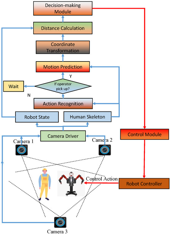
Figure 1.
Proposed human–robot collaboration system design.
3. Related Works
3.1. Methods to Solve Trajectory Optimization in MPC
When the system is linear, the constraints are affine and the cost functions are quadratic, the associated MPC optimization problem is a quadratic program. Several convex optimization algorithms have been proposed [23,24] that are fast, robust, and possess global convergence guarantees. In contrast to the first-order approaches mentioned above, Newton-type methods are able to deal with general constraints and have faster rates of convergence [25]. This leads to a considerable reduction in computation time and makes them better suited to handling real-time nonlinear problems.
The proximal averaged Newton-type method for optimal control (PANOC) is applied, considering obstacle avoidance [26]. Compared with SQP and IP, PANOC does not require the solution of linear systems or quadratic programming problems at every iteration, and it involves only very simple operations such as vector additions and scalar and inner products. Additionally, PANOC is able to converge globally to a point that satisfies the first-order optimal conditions of the problem from any initial guess. As an extension, refs. [27,28] combines the proximal averaged Newton-type method for optimal control (PANOC) with the penalty and augmented Lagrangian methods to compute approximate stationary points of non-convex problems.
Although MPC is widely used in practice, it is known that suboptimality and infeasibility caused by the numerical optimization method can compromise the stability and positive invariance (satisfaction of constraints) properties of the MPC-controlled system. There have been a few works, such as [29], that attempt to remedy this issue, but these are limited to linear dynamical systems, convex formulations, and specific numerical optimization methods. To the best of the authors’ knowledge, no results exist on the problem of NMPC stability under inexact numerical optimization. In this work, we focus on the issue of collision avoidance and demonstrate that the combination of nonlinear MPC, PANOC, and a CBF-based framework leads to a significant improvement in safety in terms of obstacle avoidance.
3.2. Safety-Critical Manipulator Control
A system is commonly defined as safe when its state remains within a chosen set, known as the safety set. This forms the basis of controlled invariance [30], that is, finding a control strategy that ensures the system always remains in the safety set. In [30], a safety filter is used in the control of a nonlinear system to restrict the desired inputs in a way that ensures the safety of the system when necessary. The method proposed in [31] formulates robust control Lyapunov and barrier functions to provide guarantees of stability and safety in the presence of model uncertainty. A control barrier function (CBF) is applied in our work to solve the collision avoidance problem. Applications of the CBF approach to the control of a redundant manipulator can be found in [32,33], which reduces the model dependence and conservativeness. As an extension, Ding et al. [34] present a purely kinematic implementation of a velocity-based CBF to match the manipulator’s configuration space with the obstacles’ space, thereby improving safety when using the CBF-based QP motion control.
4. Problem Formulation
Formally, the skeleton-format input to the action recognition and motion prediction modules is represented by 3D joint positions of m joints for a sequence of frames recorded over time, which is the same format as in [35]. The action pose at time (frame) t is . The observed time length is and the unobserved time length is for prediction.
For a single human action sequence belonging to a set of possible actions, , we have the observed and future motion matrices, and , where and and the action classification label encoded as a one-hot vector . The predicted human pose at time t is denoted as , which can be divided into the right hand’s position as the target position for the robot and the remaining body joints’ positions to identify the positions of obstacles.
Human action recognition and motion prediction are achieved using the two-stage deep learning computer vision approach introduced in [35], as depicted in Figure 2. The 3D-skeleton data stream provided by the OptiTrack motion capture system is first processed by a bidirectional LSTM and a GCN architecture incorporating the attention mechanism to extract spatial-temporal features of the human motion dynamics. The generated feature map, denoted as , is then fed simultaneously to two modules, one that performs prediction and one that performs recognition. The motion prediction task is achieved using an LSTM-based decoder, while the action recognition task is performed using a CNN followed by conditional random fields (CRF). Initially, the models are trained offline using collected HRC task samples. Following training, streaming data are fed to the model to generate the predicted future pose sequence and predicted action category . Denoting the feature extraction, motion prediction and action recognition functions within the Deep Neural Network model as , and , respectively, and , and as their trainable parameters, the extracted feature map , the estimated future motion and one-hot vector class category can be expressed as
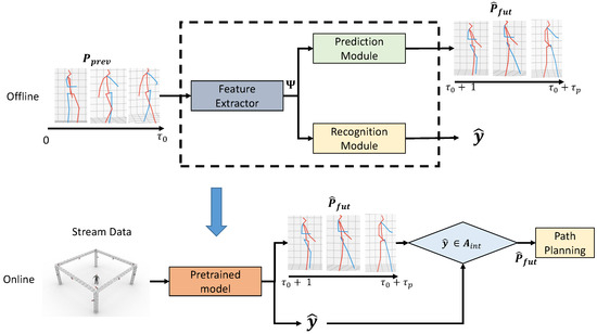
Figure 2.
Work flow from non-local graph convolution (NGC) based vision system to path planning. The outputs from the recognition and prediction modules are the estimated human action category and the future pose sequence, respectively.
If the predicted action is one that requires robot interaction, the predicted final position of the right hand (denoted ) is set as the target interactive position for the robot end-effector and the predicted final position of the other joints are set as the center of capsule-format obstacles.
The motion planning and execution control problem can then be stated as follows: Given the predicted future human motion sequence and the initial position of the robot arm, and assuming that:
- the dynamics of the manipulator are known;
- the error in the prediction of the future human position is bounded;
- the maximum velocity of the human hand is slower than that of the manipulator;
then the objective is to determine a torque input to the robot, which enables it to track the predicted position of the human’s right hand to the target position and pose, while at all times avoiding collision with the human’s body.
Denoting the set of interactive human actions requiring robot interaction as , where , the motion prediction and path planning tasks are triggered if the predicted HRC task , as shown in Figure 1.
5. NMPC Motion Planning Scheme
5.1. System Description
To model the n-DOF robotic manipulator (chosen as the right arm of our Baxter robot) with joint positions , we consider an input-affine nonlinear system of the form
where is the the state of the system and is the control input. Functions and are continuously differentiable in .
Consider an n-degrees-of-freedom manipulator with equations of motion defined as
where is a symmetric positive definite matrix, is a matrix of Coriolis and centrifugal forces terms, is a vector of gravitational forces, are the joint positions, and is the kinematic transformation from the joint angle positions to the Cartesian position of the end-effector . We consider the joint torque as the system input and as the system output.
Defining as the Jacobian matrix, it follows that
By substituting (5a) into (3), the Cartesian robotic system dynamics can be expressed as
where , , and is the vector of generated control forces. denotes the pseudo-inverse of , that is:
For notational simplicity, , , will be used to denote , ), , respectively. The system (2) is converted from joint space to task space, which can be expressed as
5.2. Minimum Distance Calculation
The minimum distance is the main input for most collision avoidance, HRI, robot decision-making, and robot navigation methods [36]. Given the joint coordinates provided by the skeletal tracking algorithm and the point clouds on the boundary of the human body, bounding capsules (cylinders with semi-spherical ends) can be computed for the human body compo as a simplified representation of the human in the distance calculation. We generate minimum bounding capsules along the bones in the skeleton, as shown in Figure 3. This is repeated for the predicted skeleton in each frame over the prediction horizon. For the 32-joint skeleton model representation, is the position of the center of the right hand.
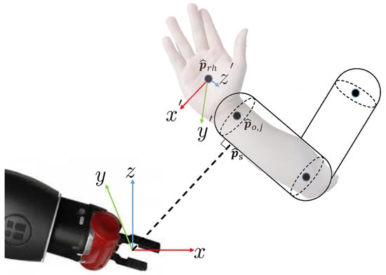
Figure 3.
Calculation of the distance, position, and orientation of the capsules for the representation of humans.
We chose the capsules model to represent robot links since it considers both the skeleton and the boundary of the human, which models the non-geometric shape of the human body [37]. The 32-joint skeleton model, as used in the Human 3.6 M dataset [38], maps to a total of 15 capsules for the human body. The approach to measure the distance between capsules is depicted in Figure 3. The distance calculation is implemented using the GJK (Gilbert–Johnson–Keerthi) algorithm [18].
The algorithm returns , the minimum distance between the boundary of the capsules representing the human and the robot in the HRC task at time t.
5.3. Nonlinear Model Predictive Control for Collision Avoidance
The robot’s objective is for its end-effector to follow the estimated position of the human’s right hand while avoiding collisions. To that end, we propose an NMPC formulation as a high-level control system that commands angular velocity references to a low-level control system (see Section 6.2). The overall controller architecture is shown in Figure 4.
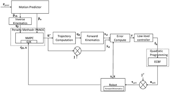
Figure 4.
NMPC-based motion planning system.
The input of the high-level control system is the joint velocity commands . At every sampling time instant, we need to solve a finite-horizon optimal control problem with prediction horizon , stage cost function ℓ, and terminal cost function , where ℓ and are given by
and
respectively. Here, is an error metric between the given Cartesian goal and the current Cartesian state of the robot . The reference position is obtained by the motion predictor. and are constant weight matrices for terms in the terminal cost function, while and are the weight matrices for terms in the stage cost function. Following [39], the error function is defined as
where matrix is built from the desired quaternion, which remains constant during the optimization.
The initial and final configurations of the robot and are obtained using the inverse kinematics function , which converts the Cartesian end effector poses (position and orientation) to the corresponding joint positions. Using the GJK algorithm, the minimum distance calculation at time t is performed based on the Cartesian coordinates of the robot, , and the predicted human pose, . The distance between the end-effector and the predicted operator’s position must be greater than the minimum safe distance . The value of is chosen to be greater than the maximum prediction error bound to guarantee the safety of humans. The constraints are described as
where denotes the state of the robotic arm. The control actions are constrained in the set . Then, the optimal solution is obtained by minimizing the optimal control cost function, that is,
subject to the constraints (Section 5.3).
In this work, we solve the NMPC problem using a numerical optimization method. To that end, we convert the above problem to a discrete-time optimal control problem using an explicit discretization and integration method. Assuming that , the NMPC problem in Equation (13) is reformulated to and depends on the current state , the set-point for the joint positions, input and the estimated obstacle distance computed by the GJK algorithm as follows:
subject to the constraints
By solving at every discrete time instant, we obtain the solution , , only the first value of which, , is applied to the system. is solved again at the subsequent time instant in a receding horizon fashion.
5.4. Numerical Solution
To solve numerically, we employ OpEn [27], a code generation software package that generates optimizers in the Rust programming language for deployment on embedded devices. OpEn combines the PANOC numerical algorithm with the penalty method to solve the above problem. However, OpEn requires that we cast in the following general form:
where is the decision variable, is a nonempty closed set on which it is easy to compute projections, is a continuously differentiable cost function—not necessarily convex—with the Lipschitz gradient, and are functions such that is continuously differentiable with the Lipschitz gradient.
To cast problem in this form, we choose the decision variable to be and define the sequence of functions
with . Note that contains the location of the robot in both joint space and task space at time as a function of the initial state and the sequence of control actions . This allows us to eliminate the sequence of states and define the cost function,
In order to impose the terminal condition of Equation (14d), we define
where . To impose the obstacle avoidance condition of Equation (14f), we define
for . Finally, we choose for the input constraints.
OpEn solves a series of optimization problems of the form
for some termed the inner problems. Essentially, the hard constraints of the original problem are converted into soft constraints. Starting with an initial value of c, a sequence of inner problems is solved numerically using the PANOC method while driving c to infinity and warm-starting each next inner problem with the solution of the previous one [27]. The algorithm terminates once the infeasibility, as defined in Equation (20), drops below a given tolerance, .
6. Controller Design
6.1. Trajectory Computation
Given the estimated angular velocity command , the desired joint state is updated as
Then, the generated desired joint position is used to calculate the desired Cartesian position and velocity .
6.2. Low-Level Controller
To achieve asymptotic stability, the control force input to the safety filter is defined as
where and are positive constants. A composite state error is denoted as , where and are the error of the Cartesian position and velocity, respectively. is a sign function depends on the state error. Considering the chattering problem caused by the sign function, (22) is rewritten as
where is a small positive number.
6.3. Exponential Control Barrier Function as a Safety Filter
In this section, an ECBF-based safety filter is introduced to prevent collisions with the human operator by constraining the trajectory generated by NMPC to be in a safe zone. ECBFs are formally defined as follows:
Definition 1
(ECBF [40]). Consider the system (8) and a set defined by a continuously differentiable function with relative degree . Then, is an exponential control barrier function (ECBF) if there is a , such that
where can be written as
The method for selecting is detailed in [40]. The Lie derivative of along is defined as
where is the state of the system. The Lie derivative of along is defined as .
Denote as the support point (i.e., a point on the boundary of the convex set that is closest to the robot) on the convex set representing the area of the human obstacle for the robot joint computed by GJK at time t. To ensure the robot does not collide with the moving human, the Cartesian position of the robot joints , are under the following constraints
where is a support point on the boundary of the capsule with the minimum distance to the robot joint, as shown in Figure 3. We define a candidate ECBF as
To modify the applied forces, , to guarantee safety, a quadratic programming (QP)-based safety filter is employed. Considering the position constraints with relative degree 2, the optimization problem can be formulated as minimizing the normed difference between and the actual input , in order to maintain the robot within the safety region. In other words, is the control input that minimizes the following QP:
subject to
where is as defined in (28). The robot joint torques are then obtained as . Further details on the implementation of ECBFs are given in [40].
6.4. System Stability Analysis
Proving the global stability of our ECBF-NMPC dynamic motion planning framework is challenging as it incorporates approximate numerical methods, a neural network-based motion predictor, the GJK algorithm, and a safety filter. To guarantee local asymptotic stability, a control Lyapunov constraint is incorporated into the ECBF formulation and activated when the robot is close to the destination.
Property 1
([41]). The inertia matrix and are symmetric positive definite.
Property 2
([41]). The matrix is skew-symmetric.
Definition 2
(-class function [42]). A continuous function is a -class function (denoted as ), if
- β is increasing
- .
Definition 3
(Control Lyapunov Functions [43]). Given the system (8) and the composite error , with , consider a continuously differentiable function on set , where is the safe set as defined for the ECBF (Definition 1). Then, V is a control Lyapunov function (CLF) for the system in (8) if there exist , , such that for all
The existence of a CLF implies the existence of a control law that renders the closed-loop system locally asymptotically stable [44]. The target when employing a CLF constraint is to make the composite error , which models the generalized Cartesian position and velocity errors with respect to the desired references, locally asymptotically converge to 0. Then, the problem (29) needs to satisfy both the ECBF and CLF constraints, which are written as
subject to
where is a symmetric positive definite matrix.
The candidate Lyapunov function V is defined as
Since is positive definite for all , its minimum eigenvalue is positive. Assuming that and , the inequality in (30) is satisfied with and .
Differentiating (33) with respect to time and using Property 1 to combine terms gives
Noting that , and substituting for using (6) with replaced by the modified control force , can be written as
By Property 2, , hence the derivative of V can be expressed as
According to Definition 2 and (32b), the stability of the low-level controller is guaranteed when assuming problem (32) is feasible.
7. Experimental Setup
The collaboration scenario shown in Figure 5 is a typical screwdriver usage scenario where the robot holds the screw at an initial position and delivers it to the human operator before the operator picks up the screwdriver. The operator’s responsibility is to use the screwdriver and take the screw from the robot end-effector, which stops at a safe interactive distance . Active collision avoidance is activated when the human body appears in the robot’s original trajectory. For seamless human–robot collaboration, the robot starts to calculate a new trajectory based on the predicted future pose sequence for the operator (1-sec horizon, = 20). The overall procedure for using the screwdriver is illustrated in Algorithm 1. After the initialization of the robot and the OptiTrack camera system, the software enters the main execution loop. Here, the action being undertaken by the operator is predicted at each sample instant. If an action requiring interaction is predicted, the software calls Algorithm 2 to compute the required robot joint torques in accordance with the proposed ECBF-NMPC dynamic motion planning framework.
| Algorithm 1: Vision-based screw-driver usage task execution |
 |
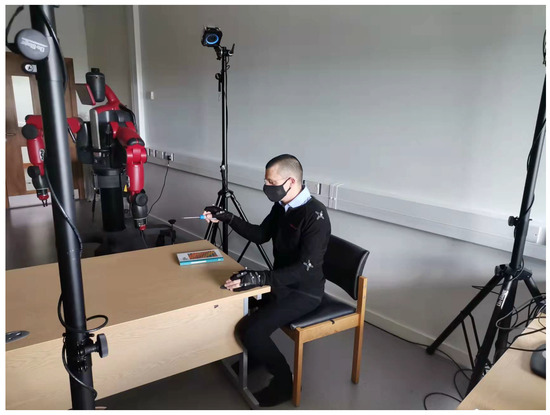
Figure 5.
Human motion capture in the screwdriver usage task.
| Algorithm 2: Motion-prediction-based path planning |
|
7.1. Motion Capture
In this work, we generate high-quality skeleton data using an OptiTrack camera system, which includes four volunteers. The volunteers enact the required behavior in a working environment with three cameras, with the volunteers’ behavior tracked from different perspectives, as shown in Figure 5. Volunteers’ movements captured in task coordinates are transformed into corresponding trajectories within the CoppeliaSim environment, enabling accurate replication of human motion patterns by the simulated agent. The generated human skeleton model has 32 joints, with joint data recorded at a sampling interval of 50 ms (i.e., 20 frames per second).
The capture space evaluated was based on typical use and had an extent of . This space can be covered by three cameras. The number of cameras required will increase for larger spaces (or volumes). We have opted for a marker-based approach in this work, regardless of the high cost of system setup and calibration, to ensure high-quality input into the perception system.
7.2. Vision System
For the vision module, we use a non-local graph convolution (NGC)-based method developed in [35] for action recognition and motion prediction. This implements a spatial-temporal attention mechanism to extract nonlocal spatial-temporal features, enabling more accurate motion prediction over longer horizons than alternative approaches. As this model, referred to as the NGC-model, performs well for the Human 3.6 M, CMU Mocap, and NTU RGB-D datasets (see [35]), we repurpose it to predict the human motion associated with the screwdriver task and classify it into one of six subtasks that constitute the overall activity, namely, ’pick up’, ’move forward’, ’take the screw’, ’operate screwdriver’, ’move backward,’ and ’put down.’ This is achieved by retraining the network with a dataset collected for the screwdriver task, consisting of skeletal data and associated subtask labels for three repetitions of the task. In this work, 4372 frames including six different actions are used for training, while 1287 frames are used for testing. Each frame includes 3D joint positions with 32 joints, as well as ground-truth action labels for each frame.
Performance of the Vision Module
As shown by the confusion matrix in Figure 6, the model achieves high prediction accuracy for each subtask (99.0%, 100%, 97.9%, 99.0%, 98.3%, and 99.5%) and an overall accuracy of 98.9%. For motion prediction, the mean per joint position error (MPJPE) is used to quantify the mean deviation between the predicted and actual locations of the human body joints in each frame. As shown in Table 1, the NGC-model achieves the lowest error compared to selected baseline models from the literature (LSTM-3LR [45], Res-sup [46], Traj-GCN [47] and SPGSN [48]). Table 1 compares the MPJPE of our model and the baselines for all actions under the same conditions, with the prediction horizon of 1000ms, showing that our model obtains the best performance for all the actions.
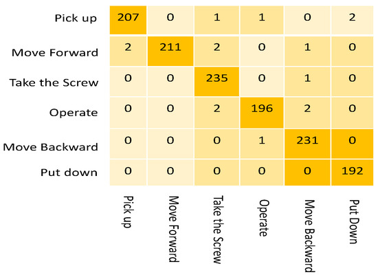
Figure 6.
Confusion matrix describing the accuracy of action recognition in the screwdriver usage task.

Table 1.
Comparison of MPJPE between models for 1000 ms prediction.
This shows that the proposed NGC model can accurately and effectively identify the intended human body movement in real-time. Using this capability, the HRC system can understand the intention of the human being when the human body begins an action, making it feasible for it to provide assistance to the human to complete the task efficiently.
7.3. Control System Performance Test
To evaluate NMPC-ECBF, we implement it for a 7-DOF Baxter robot simulated in CoppeliaSim using a standard NMPC controller as a baseline comparison [15]. The system model employed in the MPC controller is discretized using the Euler method. The weight matrices in ℓ and are selected as (1,1,1,1,1,1,1), (5,5,5,1,1,0), (0.1,0.1,0.1,0.1,0.1,0.1,0.1) and (3,3,3,0,0,0). Solution tolerances and are set for the fixed-point residual and the infeasibility, respectively. For the safety filter, safe set for input is . The parameters of the low-level controller are selected as and . Noting the maximum joint prediction errors in Figure 6, we set the safe distance () as 10 cm. The ECBF coefficients are chosen as , while (5,5,5); these values are determined within the range to satisfy Equation (32b).
In the CoppeliaSim simulation, the movement of the human is modeled using the recorded trajectories of the skeleton joints. The Baxter robot starts from different initial positions and is required to reach the estimated position without collision with the simulated human, as shown in Figure 7a.
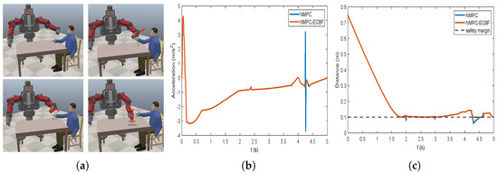
Figure 7.
(a) HRC scenario when the initial position is close to the operator. (b) The acceleration of the end-effector; (c) The minimum distance to the obstacles among all the robot links.
Under the same conditions, the acceleration and the minimum distance between the end-effector and human obstacle using different algorithms in scenario 1 are plotted in Figure 7b and 7c, respectively. The acceleration plot shows that NMPC-ECBF yields fewer abrupt changes in acceleration than the baseline NMPC path planner. The minimum distance plot highlights that the trajectory generated by NMPC violates the safe area at several points during the robot’s motion and that the inclusion of the ECBF safety filter has the desired effect of maintaining the motion within the safe area.
To prove the stability of the controller, Figure 8a,b illustrates the state of and , respectively. It shows the maximum value of is less than , which is close to 0. At the same time, the derivative of the Lyapunov function is less than 0.1, which proves the marginal stability of the system.
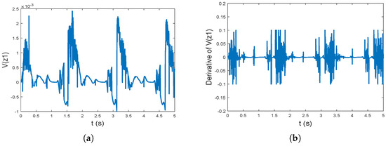
Figure 8.
(a) The plot of ; (b) The plot of .
To further assess the robustness and reliability of the controller, we perform 100 dynamic path-planning HRC experiments, with each one corresponding to a randomly generated robot start position and one of the three sets of human screwdriver usage task movement trajectories. For each experiment, we recorded the maximum acceleration of the end-effector and the minimum distance between the end-effector and the target safety margin during the task execution. Table 2 reports the mean and most extreme values observed over the 100 experiments. The results show that NMCP-ECBF is able to strictly keep the robot motion within the safe area for all 100 simulations, with no violations of the safety margin (). In contrast, the NMPC path planner frequently breaches the safety margin, with an average violation of cm and a maximum violation of cm. Furthermore, NMPC-ECBF outperforms NMPC in terms of the average and maximum joint accelerations, achieving a reduction in these values of and , respectively. It is obvious that the proposed controller improves the safety and smoothness in the HRC task.
Table 2.
Controller performance for 100 HRC task instances.
7.4. Idle Time for Agents in the HRC Scenario
Figure 9 compares the human idle time (H-IDL) and robot idle time (R-IDL) in the screwdriver usage HRC task (i.e., Scenario 1) to highlight the benefit of integrating motion prediction into HRC. The robot is triggered when the human’s action is detected to be ‘pick up’ and is stopped when the ‘take the screw’ action is detected. In the proposed screw-driver usage task, the original length of this HRC task is 14 s, which is the time used in human-human collaboration. Red blocks indicate when the operator is in an idle state, waiting for the screw to arrive. White blocks are the times the robot is idle for computation and data loading. Green blocks are the times when both agents are executing the commanded task. When employing motion-prediction-based control, the R-IDL consists of the time for motion prediction and path planning. The robot’s execution time accounts for the majority of the total time when employing the motion predictor and embedded optimization engine. In the HRC task implemented without motion prediction, the robot has to start path planning after the human operator moves their right hand to the target interactive position.
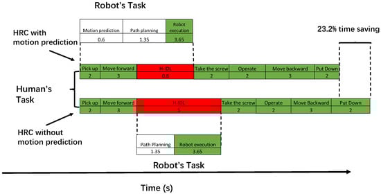
Figure 9.
Task assignment chart for the baseline approach of strict turn-taking, where each action is immediately followed by the next action of the other teammate.
After repeating the screwdriver usage task 100 times, Table 3 compares the average human idle time (H-IDL) and robot idle time (R-IDL) for the human–robot collaboration task without motion prediction. In this work, the HRC without motion prediction can be treated as a strict turn-taking task, where each agent strictly takes action after the partner finishes. The H-IDL rate is reduced by 4.1% and the R-IDL rate by 13.4% in the HRC task using the motion-prediction-based approach. Without motion prediction, the H-IDL rate and R-IDL rate are 26.3% and 7.1%, respectively. Therefore, using motion prediction reduces the idle time for both the human and the robot in the HRC task. As a result, the total execution time is reduced from 19.0 to 14.6 s, a saving of 23.2%.
Table 3.
Comparison of the idle time between the tasks with or without motion prediction.
8. Conclusions
The proposed NMPC-ECBF control framework allows a robot to safely replan its motion in the presence of a human, delivering smooth acceleration and adaptivity in the presence of uncertainty. The results demonstrate the necessity of adding a safety filter to the NMPC controller in the trajectory planning problem. This represents a promising approach for manufacturing applications due to its characteristic of strictly constraining the robot’s motion. In addition, by employing human motion prediction within the framework, tasks can be executed more efficiently with a lower idle rate achievable for both agents in an HRC task than with traditional turn-taking task execution.
Future work will be devoted to testing the proposed algorithm when there is uncertainty regarding the system dynamics (e.g., caused by joint friction). The possibility of promoting the proposed model for scenarios involving multiple robots and coworkers will also be investigated. In addition, we will explore the applicability of our approach to scenarios involving both physical and non-physical HRC interactions, with the robot switching between different control modes based on the prevailing circumstances, as determined by a higher-level supervisory system. Furthermore, we will integrate multimodal learning (e.g., radar sensors, tactile sensors, and auditory sensors) into the HRC system for more robust and safer collaboration.
Author Contributions
Methodology, D.Z.; Supervision, M.V., P.S. and S.M. All authors have read and agreed to the published version of the manuscript.
Funding
This research was funded by the Centre for Intelligent Autonomous Manufacturing Systems (i-AMS), School of Electronics, Electrical Engineering and Computer Science, Queen’s University Belfast, Belfast BT9 5AG, UK.
Data Availability Statement
Data are contained within the article.
Conflicts of Interest
The authors declare no conflicts of interest.
References
- Nicora, M.L.; Ambrosetti, R.; Wiens, G.J.; Fassi, I. Human—Robot Collaboration in Smart Manufacturing: Robot Reactive Behavior Intelligence. J. Manuf. Sci. Eng. 2021, 143, 031009. [Google Scholar] [CrossRef]
- Kumar, S.; Savur, C.; Sahin, F. Survey of Human—Robot Collaboration in Industrial Settings: Awareness, Intelligence, and Compliance. IEEE Trans. Syst. Man Cybern. Syst. 2021, 51, 280–297. [Google Scholar] [CrossRef]
- Cao, R.; Cheng, L.; Li, H. Passive Model-Predictive Impedance Control for Safe Physical Human–Robot Interaction. IEEE Trans. Cogn. Dev. Syst. 2024, 16, 426–435. [Google Scholar] [CrossRef]
- Han, L.; Zhao, L.; Huang, Y.; Xu, W. Variable admittance control for safe physical human–robot interaction considering intuitive human intention. Mechatronics 2024, 97, 12. [Google Scholar] [CrossRef]
- Wang, W.; Li, R.; Chen, Y.; Diekel, Z.M.; Jia, Y. Facilitating human–robot collaborative tasks by teaching-learning-collaboration from human demonstrations. IEEE Trans. Autom. Sci. Eng. 2018, 16, 640–653. [Google Scholar] [CrossRef]
- Terreran, M.; Barcellona, L.; Ghidoni, S. A general skeleton-based action and gesture recognition framework for human–robot collaboration. Robot. Auton. Syst. 2023, 170, 104523. [Google Scholar] [CrossRef]
- Qi, W.; Ovur, S.E.; Li, Z.; Marzullo, A.; Song, R. Multi-sensor Guided Hand Gestures Recognition for Teleoperated Robot using Recurrent Neural Network. IEEE Robot. Autom. Lett. 2021, 6, 6039–6045. [Google Scholar] [CrossRef]
- Quintas, J.; Martins, G.S.; Santos, L.; Menezes, P.; Dias, J. Toward a Context-Aware Human–Robot Interaction Framework Based on Cognitive Development. IEEE Trans. Syst. Man Cybern. Syst. 2019, 49, 227–237. [Google Scholar] [CrossRef]
- Huck, T.P.; Münch, N.; Hornung, L.; Ledermann, C.; Wurll, C. Risk assessment tools for industrial human-robot collaboration: Novel approaches and practical needs. Saf. Sci. 2021, 141, 105288. [Google Scholar] [CrossRef]
- Chemweno, P.; Pintelon, L.; Decre, W. Orienting safety assurance with outcomes of hazard analysis and risk assessment: A review of the ISO 15066 standard for collaborative robot systems. Saf. Sci. 2020, 129, 104832. [Google Scholar] [CrossRef]
- Ide, S.; Takubo, T.; Ohara, K.; Mae, Y.; Arai, T. Real-time trajectory planning for mobile manipulator using model predictive control with constraints. In Proceedings of the 2011 8th International Conference on Ubiquitous Robots and Ambient Intelligence (URAI), Incheon, Republic of Korea, 23–26 November 2011; pp. 244–249. [Google Scholar]
- Salaj, M.; Gulan, M. Pendubot control scheme based on nonlinear MPC and MHE exploiting parallelization. In Proceedings of the 2015 IEEE 19th International Conference on Intelligent Engineering Systems (INES), Bratislava, Slovakia, 3–5 September 2015; pp. 353–358. [Google Scholar]
- Su, H.; Schmirander, Y.; Li, Z.; Zhou, X.; Ferrigno, G.; Momi, E.D. Bilateral Teleoperation Control of a Redundant Manipulator with an RCM Kinematic Constraint. In Proceedings of the 2020 IEEE International Conference on Robotics and Automation (ICRA), Paris, France, 31 May–31 August 2020; pp. 4477–4482. [Google Scholar]
- Li, W.; Xiong, R. Dynamical obstacle avoidance of task-constrained mobile manipulation using model predictive control. IEEE Access 2019, 7, 88301–88311. [Google Scholar] [CrossRef]
- Oleinikov, A.; Kusdavletov, S.; Shintemirov, A.; Rubagotti, M. Safety-Aware Nonlinear Model Predictive Control for Physical Human-Robot Interaction. IEEE Robot. Autom. Lett. 2021, 6, 5665–5672. [Google Scholar] [CrossRef]
- Rawlings, J.; Mayne, D. Model Predictive Control: Theory, Computation, and Design; Nob Hill Publishing: Madison, WI, USA, 2022; Volume 2. [Google Scholar]
- Wolf, I.J.; Marquardt, W. Fast NMPC schemes for regulatory and economic NMPC–A review. J. Process Control 2016, 44, 162–183. [Google Scholar] [CrossRef]
- Secil, S.; Ozkan, M. Minimum distance calculation using skeletal tracking for safe human-robot interaction. Robot. Comput. Integr. Manuf. 2022, 73, 102253. [Google Scholar] [CrossRef]
- Wang, H.; Peng, J.; Zhang, F.; Zhang, H.; Wang, Y. High-order control barrier functions-based impedance control of a robotic manipulator with time-varying output constraints. ISA Trans. 2022, 129, 361–369. [Google Scholar] [CrossRef]
- Son, T.D.; Nguyen, Q. Safety-critical control for non-affine nonlinear systems with application on autonomous vehicle. In Proceedings of the 2019 IEEE 58th Conference on Decision and Control (CDC), Nice, France, 11–13 December 2019; pp. 7623–7628. [Google Scholar]
- Wang, C.; Meng, Y.; Li, Y.; Smith, S.L.; Liu, J. Learning control barrier functions with high relative degree for safety-critical control. In Proceedings of the 2021 European Control Conference (ECC), Delft, The Netherlands, 29 June–2 July 2021; pp. 1459–1464. [Google Scholar]
- Liu, H.; Wang, L. Human motion prediction for human-robot collaboration. J. Manuf. Syst. 2017, 44, 287–294. [Google Scholar] [CrossRef]
- Lindqvist, B.; Mansouri, S.S.; Agha-mohammadi, A.A.; Nikolakopoulos, G. Nonlinear MPC for collision avoidance and control of UAVs with dynamic obstacles. IEEE Robot. Autom. Lett. 2020, 5, 6001–6008. [Google Scholar] [CrossRef]
- Lindqvist, B.; Mansouri, S.S.; Kanellakis, C.; Nikolakopoulos, G. Collision Free Path Planning based on Local 2D Point-Clouds for MAV Navigation. In Proceedings of the 2020 28th Mediterranean Conference on Control and Automation (MED), Saint-Raphaël, France, 16–19 June 2020; pp. 538–543. [Google Scholar]
- Jerez, J.L.; Goulart, P.J.; Richter, S.; Constantinides, G.A.; Kerrigan, E.C.; Morari, M. Embedded online optimization for model predictive control at megahertz rates. IEEE Trans. Autom. Control 2014, 59, 3238–3251. [Google Scholar] [CrossRef]
- Sathya, A.; Sopasakis, P.; Van Parys, R.; Themelis, A.; Pipeleers, G.; Patrinos, P. Embedded nonlinear model predictive control for obstacle avoidance using PANOC. In Proceedings of the 2018 European control conference (ECC), Limassol, Cyprus, 12–15 June 2018; pp. 1523–1528. [Google Scholar]
- Sopasakis, P.; Fresk, E.; Patrinos, P. OpEn: Code generation for embedded nonconvex optimization. IFAC-PapersOnLine 2020, 53, 6548–6554. [Google Scholar] [CrossRef]
- Trimble, S.; Naeem, W.; McLoone, S.; Sopasakis, P. Context-aware robotic arm using fast embedded model predictive control. In Proceedings of the 2020 31st Irish Signals and Systems Conference (ISSC), Letterkenny, Ireland, 11–12 June 2020; pp. 1–6. [Google Scholar]
- Rubagotti, M.; Patrinos, P.; Bemporad, A. Stabilizing Linear Model Predictive Control Under Inexact Numerical Optimization. IEEE Trans. Autom. Control 2014, 59, 1660–1666. [Google Scholar] [CrossRef]
- Gurriet, T.; Mote, M.; Singletary, A.; Nilsson, P.; Feron, E.; Ames, A.D. A scalable safety critical control framework for nonlinear systems. IEEE Access 2020, 8, 187249–187275. [Google Scholar] [CrossRef]
- Nguyen, Q.; Sreenath, K. Robust safety-critical control for dynamic robotics. IEEE Trans. Autom. Control 2022, 67, 1073–1088. [Google Scholar] [CrossRef]
- Singletary, A.; Kolathaya, S.; Ames, A.D. Safety-critical kinematic control of robotic systems. IEEE Control Syst. Lett. 2021, 6, 139–144. [Google Scholar] [CrossRef]
- Landi, C.T.; Ferraguti, F.; Costi, S.; Bonfè, M.; Secchi, C. Safety barrier functions for human-robot interaction with industrial manipulators. In Proceedings of the 2019 18th European Control Conference (ECC), Naples, Italy, 25–28 June 2019; pp. 2565–2570. [Google Scholar]
- Ding, X.; Wang, H.; Ren, Y.; Zheng, Y.; Chen, C.; He, J. Online Control Barrier Function Construction for Safety-Critical Motion Control of Manipulators. IEEE Trans. Syst. Man Cybern. Syst. 2024, 54, 4761–4771. [Google Scholar] [CrossRef]
- Zhang, D.; Vien, N.A.; Van, M.; McLoone, S. Non-local Graph Convolutional Network for joint Activity Recognition and Motion Prediction. In Proceedings of the 2021 IEEE/RSJ International Conference on Intelligent Robots and Systems (IROS), Prague, Czech Republic, 27 September–1 October 2021; pp. 2970–2977. [Google Scholar]
- Safeea, M.; Mendes, N.; Neto, P. Minimum distance calculation for safe human robot interaction. Procedia Manuf. 2017, 11, 99–106. [Google Scholar] [CrossRef]
- Lin, H.C.; Liu, C.; Fan, Y.; Tomizuka, M. Real-time collision avoidance algorithm on industrial manipulators. In Proceedings of the 2017 IEEE Conference on Control Technology and Applications (CCTA), Maui, HI, USA, 27–30 August 2017; pp. 1294–1299. [Google Scholar]
- Ionescu, C.; Papava, D.; Olaru, V.; Sminchisescu, C. Human3. 6m: Large scale datasets and predictive methods for 3d human sensing in natural environments. IEEE Trans. Pattern Anal. Mach. Intell. 2013, 36, 1325–1339. [Google Scholar] [CrossRef] [PubMed]
- Hu, S.; Babaians, E.; Karimi, M.; Steinbach, E. NMPC-MP: Real-time Nonlinear Model Predictive Control for Safe Motion Planning in Manipulator Teleoperation. In Proceedings of the 2021 IEEE/RSJ International Conference on Intelligent Robots and Systems (IROS), Prague, Czech Republic, 27 September–1 October 2021; pp. 8309–8316. [Google Scholar]
- Nguyen, Q.; Sreenath, K. Exponential control barrier functions for enforcing high relative-degree safety-critical constraints. In Proceedings of the 2016 American Control Conference (ACC), Boston, MA, USA, 6–8 July 2016; pp. 322–328. [Google Scholar]
- He, W.; Ge, S.S.; Li, Y.; Chew, E.; Ng, Y.S. Neural network control of a rehabilitation robot by state and output feedback. J. Intell. Robot. Syst. 2015, 80, 15–31. [Google Scholar] [CrossRef]
- Grandia, R.; Taylor, A.J.; Singletary, A.; Hutter, M.; Ames, A.D. Nonlinear model predictive control of robotic systems with control lyapunov functions. arXiv 2020, arXiv:2006.01229. [Google Scholar] [CrossRef]
- Minniti, M.V.; Grandia, R.; Farshidian, F.; Hutter, M. Adaptive CLF-MPC with application to quadrupedal robots. IEEE Robot. Autom. Lett. 2021, 7, 565–572. [Google Scholar] [CrossRef]
- Sontag, E.D. A Lyapunov-Like Characterization of Asymptotic Controllability. SIAM J. Control Optim. 1983, 21, 462–471. [Google Scholar] [CrossRef]
- Gui, L.Y.; Zhang, K.; Wang, Y.X.; Liang, X.; Moura, J.M.; Veloso, M. Teaching robots to predict human motion. In Proceedings of the 2018 IEEE/RSJ International Conference on Intelligent Robots and Systems (IROS), Madrid, Spain, 1–5 October 2018; pp. 562–567. [Google Scholar]
- Martinez, J.; Black, M.J.; Romero, J. On human motion prediction using recurrent neural networks. In Proceedings of the IEEE Conference on Computer Vision and Pattern Recognition, Honolulu, HI, USA, 21–26 July 2017; pp. 2891–2900. [Google Scholar]
- Mao, W.; Liu, M.; Salzmann, M.; Li, H. Learning trajectory dependencies for human motion prediction. In Proceedings of the IEEE/CVF International Conference on Computer Vision, Seoul, Republic of Korea, 27 October–2 November 2019; pp. 9489–9497. [Google Scholar]
- Li, M.; Chen, S.; Zhang, Z.; Xie, L.; Tian, Q.; Zhang, Y. Skeleton-Parted Graph Scattering Networks for 3D Human Motion Prediction. In Proceedings of the Computer Vision—ECCV: 17th European Conference, Tel Aviv, Israel, 23–27 October 2022; Avidan, S., Brostow, G., Cissé, M., Farinella, G.M., Hassner, T., Eds.; Springer: Cham, Switzerland, 2022; pp. 18–36. [Google Scholar]


Disclaimer/Publisher’s Note: The statements, opinions and data contained in all publications are solely those of the individual author(s) and contributor(s) and not of MDPI and/or the editor(s). MDPI and/or the editor(s) disclaim responsibility for any injury to people or property resulting from any ideas, methods, instructions or products referred to in the content. |
© 2025 by the authors. Licensee MDPI, Basel, Switzerland. This article is an open access article distributed under the terms and conditions of the Creative Commons Attribution (CC BY) license (https://creativecommons.org/licenses/by/4.0/).