Abstract
The rising complexity of industrial systems following the Industry 4.0 era involves new challenges and the need for innovative solutions. In the context of arising digital technologies, Digital Twins represent a holistic solution to overcome heterogeneity and to achieve remote and dynamic control of cyber–physical systems. In common reference architectures, decision-making modules are usually integrated for system and process optimization. This work aims at introducing the adoption of a multi-purpose simulation module in a Digital Twin environment, with the objective of proving its versatility for different scopes. This is implemented in a relevant laboratory environment, strongly employed for the test and validation of mechatronic solutions. The paper starts from revising the common techniques adopted for decision-making modules in Digital Twin frameworks, proposing then a multi-purpose approach based on physics simulation. Performance profiling of the simulation environment demonstrates the potential of real-time-capable simulation while also revealing challenges related to computational load and communication latency. The outcome of this work is to provide the reader with an exemplary modular arrangement for the integration of such module in Digital Twin applications, highlighting challenges and limitations related to computational effort and communication.
1. Introduction
Several industrial sectors, such as manufacturing and automation sectors primarily, have undergone significant changes in recent years, driven by the demand for high variability, complexity, and flexibility, requirements which nowadays set a trespass level for industrial systems [1]. Moreover, the tendency of industrial systems is shifting to higher grades of automatization, which assures flexible capabilities and enhances the potentialities of such systems but also includes the need for advanced competences and tools. Concurrently, significant changes have been also introduced by the gradual shift to the era of digitization, which is being embraced by the industry reality as new digitalized promising technologies flourish [2]. Advancements in digital technologies have indeed led to transformations in product integration phases throughout their lifecycle, underscoring the importance of establishing up-to-date digital representations of systems’ equipment [3].
This shift towards modern manufacturing practices, often termed as smart manufacturing, represents one of the prevailing trends today. Smart manufacturing represents a paradigm shift in industrial production, integrating advanced technologies to enhance efficiency, flexibility, and responsiveness [4]. At its core, digitization plays a crucial role by enabling real-time data collection, process monitoring, and intelligent decision-making. The foundation of this concept sees its strong basis in enhanced visibility and control over operations from the point of view of manufacturers [5]. By leveraging digital tools, smart manufacturing enhances productivity, supports predictive maintenance, and fosters innovation, making it a cornerstone of modern industrial transformation [3].
Among the enabling technologies of digital transformation, the Digital Twin (DT) stands out as a key bridge between physical and digital systems [6]. A DT is typically defined as a real-time synchronized virtual replica of a physical entity, with automated bidirectional data exchange [7]. Its development allows real-time monitoring, control, and optimization in manufacturing, enhancing system efficiency and decision-making [8]. Simulation technologies have, therefore, proliferated, offering valuable tools for optimizing production workflows, minimizing downtime, and reducing costs [9].
Despite these advantages, creating fully functional DTs still presents challenges, especially regarding real-time synchronization [8]. Computational burdens, limited software capabilities, and integration barriers between proprietary systems often hinder seamless implementation [10]. Nevertheless, recent advancements show promise for overcoming these obstacles. Crucially, simulation-based optimization is a primary objective of DTs. While basic DT applications focus on status monitoring, advanced implementations aim for real-time operational optimization [11]. Depending on the objective, such as task sequencing or energy efficiency, various methods have emerged. Common strategies include integrating decision-making modules based on simulation or AI, especially Machine Learning techniques [12]. This is where this work comes in, with the aim to answer the following research questions (RQs):
- RQ1: Which Digital Twin architectures already exist, and which typologies of physical systems are they applied to?
- RQ2: Which techniques are exploited for the development of decision-oriented module in such architectures?
- RQ3: Which techniques are peculiarly efficient for industrial mechatronic systems?
In order to answer to the listed RQs, a series of research objectives (ROs) is addressed by this work. This paper first reviews successful DT architectures (RO1) and presents an overview of modeling strategies for integrating decision-oriented modules within DT frameworks (RO2). It then proposes a simulation-based multi-purpose layer aimed at optimizing the operation of mechatronic equipment in a laboratory environment (RO3). A case study involving a small-scale transfer line is developed using physics-based 3D simulation, designed to replicate an industrial-like setting. Preliminary simulations assess the real-time performance of the Digital Model (DM), focusing on computational efficiency and communication latency, to assess the feasibility of responsive decision-making. Synchronization with the physical system is achieved via REST API, enabling bi-directional communication between the virtual and real systems. Ultimately, this work contributes to establishing a fully synchronized simulation-optimized DT demonstrator (RO4), with the functional role, limitations, and future prospects of the DT framework discussed throughout the document.
The paper is structured as follows: In Section 2, a state-of-the-art overview of the concept of DT and of existing simulation-based DT architectures is presented. The focus of Section 3 is to revise common techniques used in DT architectures, specifically for industrial mechatronic systems, to develop decision-oriented modules. The outcome of this section is the proposal of a simulation-based multi-purpose layer, which is then context-adapted to the industrial case scenario analyzed by this work. Section 4 presents the details of the practical case study proposed to pursue the previously mentioned ROs, from the simulation setup to the data flow structuring. While in Section 5 performance results for the several simulation operations are presented and discussed, Section 6 highlights conclusions and potential future developments of this work.
2. Literature Review
The purpose of the following section is to revise the origin of the concept of DT, briefly highlighting its characteristics and providing some examples, specifically related to industrial contexts. Moreover, a detailed overview of DT architectures from the literature is reported; the peculiar focus of this subsection is on architectures exploiting simulation-based tools for the sake of modeling and optimization of mechanical systems.
2.1. Theoretical Background
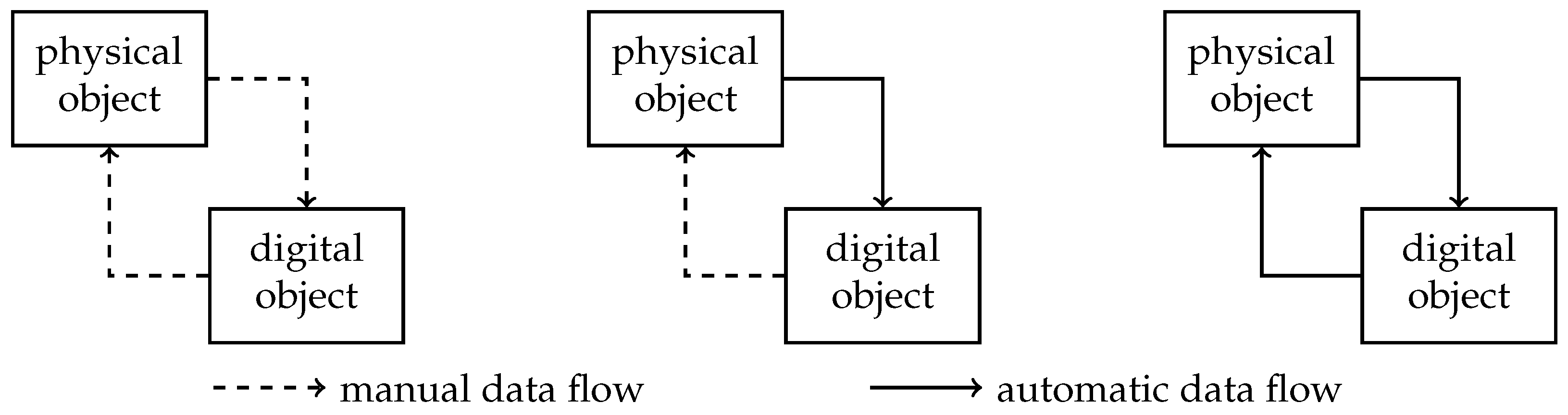
The adoption of DTs as virtual representations of physical systems is gaining significant traction within the global scientific community. Their ability to enhance prediction, control, and optimization has positioned DTs as a key enabler of digital transformation across various industries [13]. Consequently, supporting technologies are continually evolving, driving an ongoing trend toward more sophisticated and integrated DT solutions [14,15]. In essence, a DT serves as an exact virtual counterpart of a physical entity, facilitating real-time data exchange between the two. The automation of this real-time information flow is a defining characteristic that distinguishes DTs from other digital representations [16]. Digital transformation steps typically involve a digital object corresponding to a physical system, as represented in Figure 1:
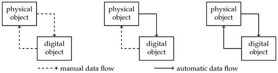
Figure 1.
Graphical representations of DM (left), DS (middle), and DT (right).
- Digital Model (DM): Data exchange between the physical and virtual worlds occurs manually.
- Digital Shadow (DS): Data from the physical system is autonomously acquired, but human intervention is still required to transfer insights, such as simulation results or production metrics, back to the real world.
- Digital Twin (DT): Features fully integrated bidirectional data flows, enabling continuous synchronization between the physical and digital domains.
The aforementioned definition refers to what in the literature is called the Object Twin. As introduced by [17], in a cyber–physical system (CPS), it is also important to address two other typologies of DT: (a) the Process Twin, which represents the process sequence in the virtual world; (b) the Phenomenon Twin, which can be related to involved phenomena occurring in the system in a given manufacturing environment. Together, these three DT typologies have the capability to fully represent the CPS operation in the virtual environment.
For a DT to function effectively, three key components are essential [18]:
- Simulation: Capturing the full behavioral characteristics of the physical system at any given moment.
- Synchronization: Ensuring the virtual counterpart accurately reflects the real-world system in real time.
- Optimization: Enabling data-driven enhancements that allow the physical system to operate at peak efficiency.
DTs have become one of the most widely discussed topics in the field of digital transformation [19]. Their ability to create digital replicas of physical systems, such as manufacturing plants and complex mechatronic structures, delivers numerous advantages, including improved prediction accuracy, cost savings, and enhanced performance. As research continues to advance, the role of DTs in industrial and scientific applications is only becoming more pronounced, solidifying their position as a cornerstone of modern digitalization efforts.
2.2. Digital Twin Architectures
Digital Twin (DT) architectures are typically organized in layers reflecting the system’s structural and functional hierarchy. At minimum, an effective DT requires three core layers: the physical layer (the real-world system), the virtual layer (its digital replica), and a communication layer to enable data exchange between the two [20,21]. Early DT frameworks, especially those developed before 2021, often adhered to this tri-layer structure.
For example, a three-layer architecture is applied in [22] to an industrial case using the Digital Twin as a Service (DTaaS) model, enabling real-time monitoring, predictive maintenance, and remote control. Similarly, in [23], a DT-based cybersecurity framework for Industrial Automation and Control Systems (IACS) is presented, emphasizing secure synchronization and attack prevention through a layered architecture.
As the field evolved, extended models emerged to support advanced functionalities. The ISO 23247-2:2021 standard [24] provides a structured reference architecture for DTs in manufacturing, introducing a four-layer model to support domain-specific implementations, enhanced interoperability, and real-time system optimization. The four layers are as follows:
- Observable Manufacturing layer: Includes physical entities like personnel, equipment, and processes.
- Device Communication layer: Handles data collection from sensors and control of manufacturing devices.
- Digital Twin layer: Provides real-time synchronization, simulation, and data analytics of physical elements.
- User layer: Interfaces with humans and external systems for decision-making and visualization.
The ISO 23247-2:2021 standard offers a structured reference architecture for DTs in manufacturing, promoting modularity, interoperability, and real-time synchronization between physical and digital entities [24]. It introduces functional entities (FEs) that manage data collection, synchronization, analytics, simulation, and security, core components for enabling predictive maintenance and process optimization. While ISO-driven DT frameworks, such as the ISO 23247 standard, offer valuable baseline structures and guidelines, they, however, typically rely on rigid ontologies and predefined architectures primarily oriented toward automation and monitoring. Consequently, they often lack sufficient flexibility, adaptability, and support for higher levels of autonomy or effective human–machine interaction, which are crucial requirements in advanced manufacturing environments and dynamic mechatronic systems.
Building on this foundation, various enhanced DT architectures have been proposed. In [25], a four-layer simulation-based architecture is presented for a conveyor system, featuring AI-driven optimization for predictive maintenance and fault detection. Similarly, Ref. [26] integrates the DT into an Activity Resource Type Instance (ARTI) reference model, introducing a decision-making layer that adjusts process parameters in real time to improve system resilience.
More advanced structures are seen in works like [27], where a five-layer architecture incorporates an intelligent service layer for semantic interoperability and a system administration layer for CPS coordination. In [28], a six-layer architecture combines physical and digital infrastructure through vendor-neutral technologies (e.g., SQL), ensuring secure and scalable communication from edge to cloud.
To conclude, it is more than evident that the most recent DT architecture examples listed in this section are joined by a common factor: the presence of a “reasoner”, which is the main responsible for the decision-oriented monitoring of the system status and, possibly, for the active optimization of the system itself. The purpose of Section 3.2 is to describe and review methods and approaches commonly utilized for the creation of decision-oriented DT module; moreover, an architecture specifically applicable and designed for the purposes of this work, as well as enhanced with respect to ISO-driven DT frameworks, is proposed.
3. Proposal of Multi-Purpose Layer Architecture
The scope of this section is to firstly revise common practices and techniques employed for the development of the decision-oriented DT module uniting many of the DT architectures presented in the previous section. Based on the provided revision, a proposal for decision-oriented module architecture to be subsequently integrated into the DT framework described in this work is presented.
3.1. Implementation Practices for Decision-Oriented Modules in DT Architectures
The decision-oriented module in a DT framework is responsible for decision-making, reasoning, and optimization, enabling autonomous operations, predictive analytics, and adaptive control. To achieve this, various techniques and practices are employed to process data and optimize system performance in real time. A detailed list is below reported.
3.1.1. Artificial Intelligence (AI) and Machine Learning (ML)
AI-driven approaches play a crucial role in learning system behaviors for prediction and optimization purposes [23]. Some common methods include the following:
- Supervised Learning: Utilized for predictive maintenance and quality control by training models on historical sensor data [29].
- Unsupervised Learning: Applied for anomaly detection and clustering of process states.
- Reinforcement Learning (RL): Enables autonomous decision-making by learning optimal strategies through trial and error, particularly useful in process optimization and robotic control [30].
3.1.2. Knowledge-Based Reasoning and Ontologies
A structured representation of knowledge is fundamental for semantic reasoning and interoperability in complex industrial systems. As a result, ontology-based decision support systems can be used to infer relationships between components and processes [27]. There are also rule-based expert systems, which encode if-then rules to enable DTs to respond autonomously to different operational scenarios.
3.1.3. Fuzzy Logic and Hybrid AI-Models
Two typologies of models can be found in the literature:
- Fuzzy Logic Controllers (FLCs): Handle uncertainty and imprecise data for real-time control decisions in manufacturing and industrial automation [26].
- Neuro-Fuzzy Systems: Combine neural networks with fuzzy logic to enhance adaptability in dynamic environments [31].
3.1.4. Edge and Cloud Computing for Real-Time Decision Making
The decision-oriented module often relies on a hybrid computing architecture, distributing computational tasks between (a) edge computing, which handles low-latency decision-making by processing real-time sensor data close to the physical system [28]; (b) cloud computing, which stores and analyzes large-scale historical data, supporting long-term optimization strategies.
3.1.5. Simulation-Based Optimization
Simulation-based reasoning is employed to test different operational strategies before implementation in the physical system, as reported in [24]. Some examples are as follows:
- Multi-Agent Simulations (MASs): Represents distributed systems where virtual agents interact to find the most efficient configuration [25].
- Digital Twin as a Service (DTaaS): Provides real-time cloud-based simulations for adaptive decision-making and control [22].
- Physics-Based Simulations: Used in cyber–physical systems to model mechanical behaviors, energy consumption, and process variations [32].
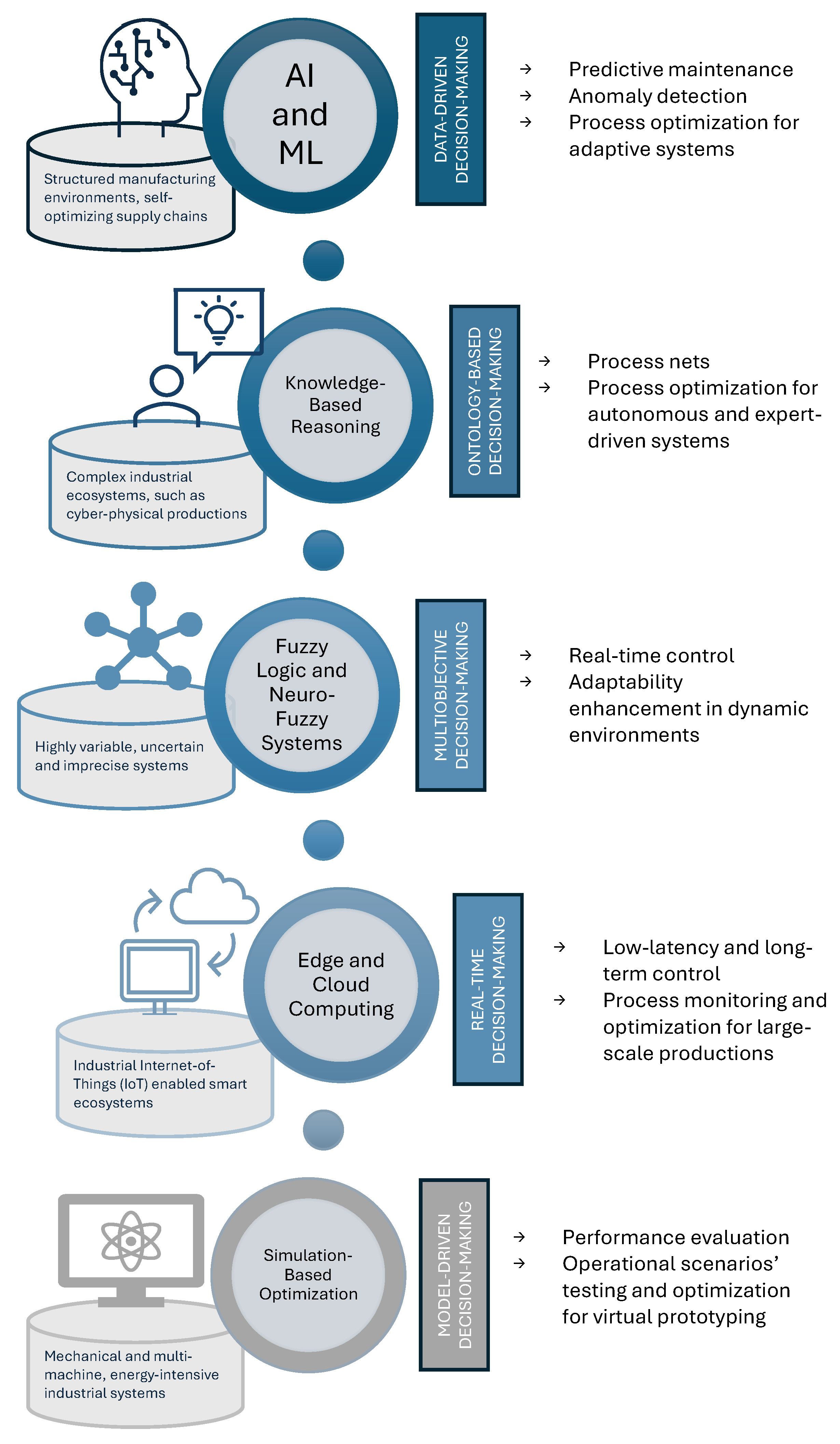
By integrating one of the above-mentioned techniques, the decision-oriented module of a DT architecture enables automated decision-making, predictive analytics, and system self-optimization. These technologies empower real-time operational efficiency and ensure the DT functions as an adaptive, autonomous system in smart manufacturing and cyber–physical environments. It is, however, worth mentioning that each method is particularly effective for a different physical system typology and in particular cases, factors which can highly influence the choice of the most suitable method to utilize. Figure 2 is intended to provide the reader with a summarizing overview of the aforementioned methodologies.
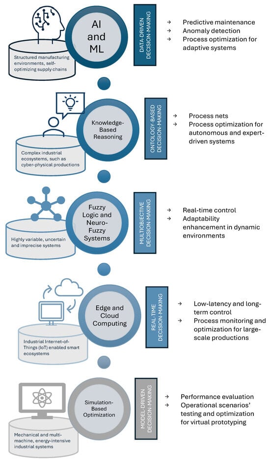
Figure 2.
Graphical summary of methodologies (center), common systems to which they are applied (left) and peculiarities (right).
3.2. Proposal for Simulation-Based Multi-Purpose Layer
As stated in Section 2.1, simulation is the first key point for the successful creation of a fully furnished and functional DT. Thanks to simulation, indeed, the system in the exam can be faithfully represented by its virtual replica, which should encompass not only its behavioral but also its physical characteristics [33]. Based on the level of detail and on the application of the DT, the simulated system can require a medium or higher level of complexity. For instance, DTs of process flows might focus more on the simulation lightness to ensure the most efficient real-time synchronization after [34]. On the contrary, the simulation of a machine element or a robotic manipulator must include its most faithful dynamic characteristics to assure that the simulated model faithfully resembles the kinematic or dynamic behavior of the system [35]. Independently of the simulation typology and complexity, simulation can also be utilized to evaluate various operational scenarios before deploying them in the physical system.
To implement a decision-oriented multi-purpose layer within the DT architecture of this work, which will be described in the next section, the authors propose the use of a physics-based simulation approach, particularly suited for industrial cyber–physical systems still in the prototyping phase. Unlike lightweight simulations that prioritize computational efficiency, physics-based models ensure a high-fidelity representation of mechanical dynamics, making them essential for accurately simulating robotic manipulators, machine elements, and complex industrial interactions.
The proposed layer lays its basis on a multi-scenario simulation strategy, where different operational conditions are tested within the virtual environment before executing them in the real system. Within this approach, a set of simulations will be configured to generate multiple possible scenarios, each reflecting a unique combination of process parameters, environmental factors, and system constraints. These simulations will serve as virtual experiments, allowing an in-depth evaluation of the system’s behavior under various conditions. Once the simulations are executed, the multi-purpose layer integrated into the DT architecture will analyze the results of each scenario, assessing key performance indicators such as productivity, efficiency, and energy consumption. Based on this evaluation, the optimal scenario will be selected and implemented in the physical system. This data-driven decision-making process will enable an adaptive and self-optimizing DT, capable of autonomously identifying the most effective operational strategy before execution, ultimately improving system reliability and resource utilization.
4. Case Study
This section is intended to provide the reader with a practical case study to which the proposal for decision-oriented multi-purpose layer architecture described by the previous section was applied. Starting with the description of the physical system in the exam, an overview of the simulation setup and of the data flow structuring in the proposed simulation-based DT architecture will be provided.
4.1. System Description
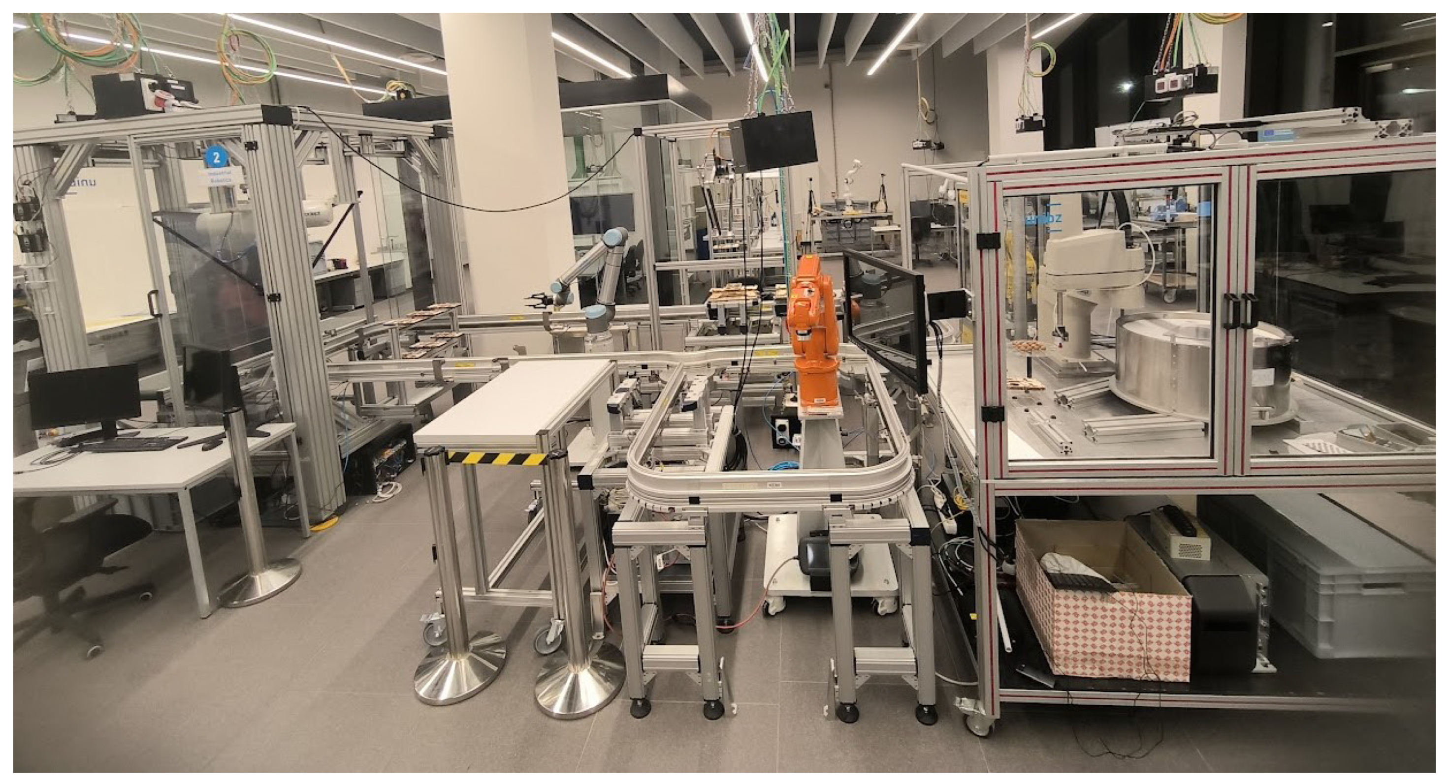
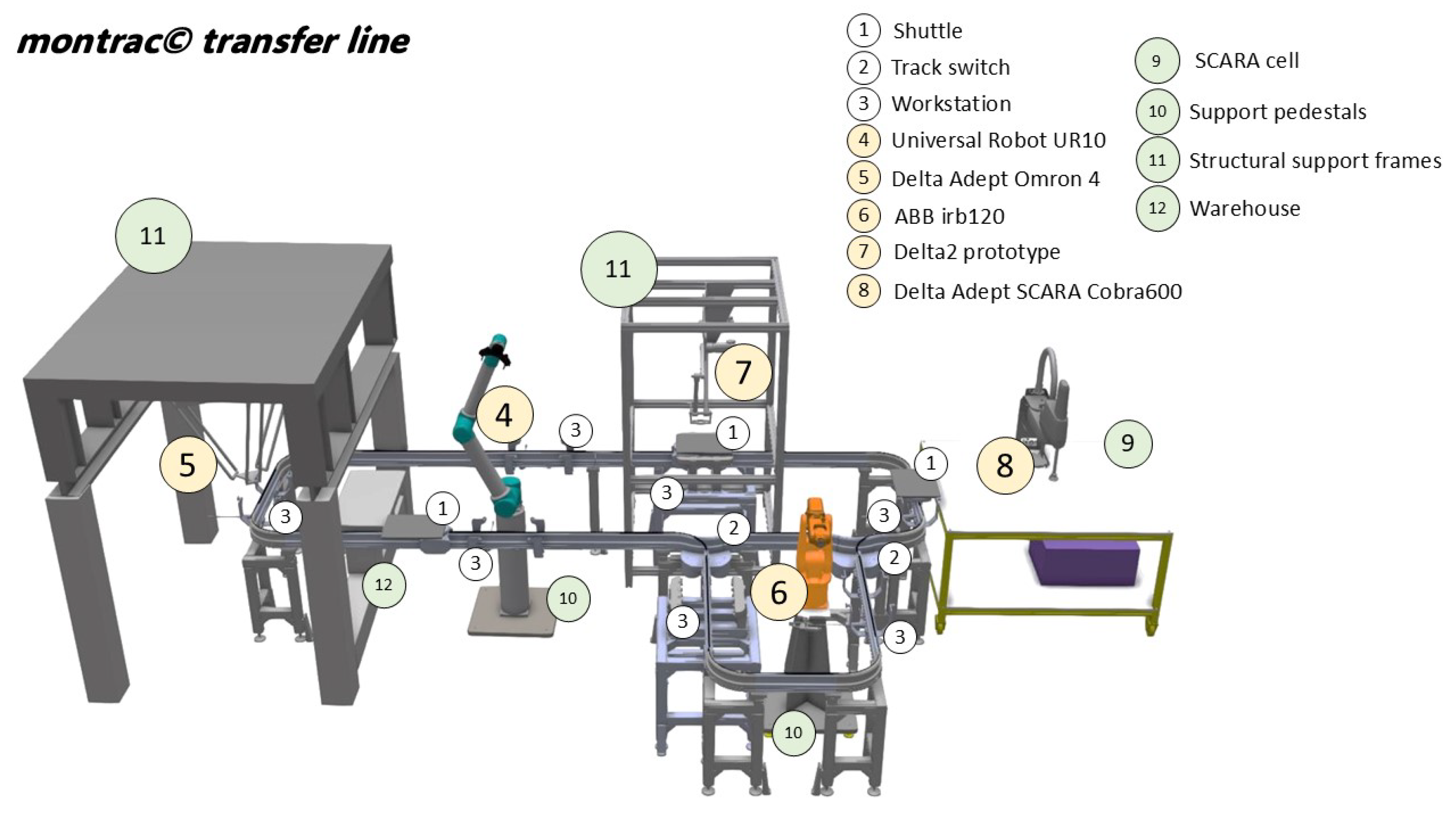
The physical system selected to achieve the objectives of this research is a flexible and intelligent transfer line, branded Montrac®, currently installed in the Smart Mini Factory laboratory [36,37] at the Free University of Bozen-Bolzano. The transfer line consists of two main rail loops, seven workstations, two switches, and three shuttles. These components are designed to function as a transportation system in a future DT-based assembly line. Within the transfer line, several robotic manipulators are currently in place and acting as agents in the system: two four-joint traditional industrial robots (ABB irb120 and Adept SCARA Cobra600); a four-arm traditional industrial parallel robot (Adept Omron 4); a prototype of a two-joint parallel robot (Delta2 manipulator); a six-joint collaborative robotic arm (Universal Robot UR10) fitted with a gripper. A representative image of the transfer line configuration in the laboratory is shown in Figure 3, where the two switches are visible in the foreground, linking the larger central rail loop with the smaller secondary loop.
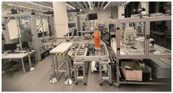
Figure 3.
Montrac® transfer line setup and robotic manipulators at the Smart Mini Factory (SMF) laboratory: (from left to right) Adept Omron 4; Universal Robot 10; Delta2 prototype; ABB irb120; Adept SCARA Cobra600.
The collaborative robotic manipulator, UR10, is located within the main rail loop, where it services two mirrored workstations and a warehouse. The ABB and Adept SCARA Cobra600 operate on a single workstation, which is directly located in an external industrial cell, where the Cobra600 is installed, together with a vibrating screen (Flexibowl 500). The Omron 4 robot reaches an external workstation beneath it, opposite with respect to the Cobra600 cell, and a small conveyor roller. The Delta2 manipulator is mounted on a fixed frame, like the Omron 4, right above another workstation. Technical details regarding robotic manipulators are further described in Section 4.2.2.
Generally speaking, the goal of this environment setup is to utilize the transfer line for small assembly operations. The shuttles are in charge of transporting the required workpieces to the destined workstations, where robotic manipulators perform assembly and dismantling operations. The UR10, which is the only collaborative robot along the line, is in charge of loading and unloading of workpieces from the warehouse.
For the purposes of this work, an important preliminary step was the characterization of the machines in action from the kinematic point of view. In order to build an accurate DM and, subsequently, a faithful DT, it is important to encompass the system characteristics and to have a clear idea of how the different parts move. As a result, two phases were conducted to characterize the system:
- Kinematic modeling: A model of the kinematics of shuttles and robots to gather information about their position, velocity, and eventually acceleration. In the case of robotic manipulators, the inverse kinematic analysis was performed for the correspondent kinematic chain to obtain joint values.
- Simulation environment setup: A replication of the kinematics in the environment of industrialPhysics in order to set up the DM of the transfer line.
4.2. Kinematic Modeling
This section aims to present the kinematic analysis of the shuttle cars and the robotic manipulators present along the transfer line.
4.2.1. Shuttle Cars
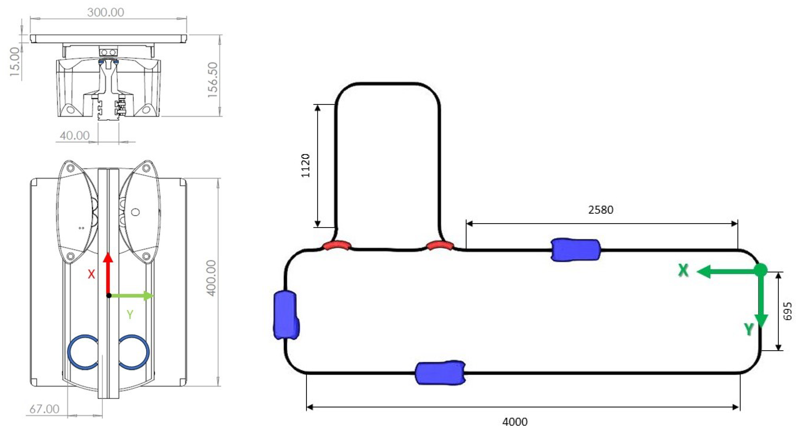
The shuttle cars moving along the transfer line in the exam can be modeled as rail-guided vehicles. Geometrical details of the shuttles and the rail path are shown in Figure 4. A particularly effective formulation for this purpose is based on the Frenet–Serret frame [38], which enables the definition of a local, curve-attached reference system that evolves as a point moves along a trajectory. This continuously rotating, non-inertial frame, commonly referred to as the TNB frame, is constructed from three orthonormal unit vectors: the tangent vector , the normal vector , and the binormal vector , with . A system composed of i rigid bodies can be described using the stacked vector of generalized coordinates:

Figure 4.
Geometry details of a shuttle car and of rail path (top view).
Each vector contains both position and orientation of the i-th body. For the specific case of three rail-guided shuttles constrained to planar motion, reduces to [39]
where denotes the planar position of shuttle i and its orientation with respect to the global frame. Kinematic constraints used to interconnect bodies or enforce motion behavior are typically encoded in a vector function:
To maintain alignment between each shuttle’s local frame and the track-defined TNB frame, an orientation constraint must be introduced. Let , , and denote the unit vectors of the shuttle’s local coordinate system (see Figure 4). The constraint can then be expressed as
This ensures that each shuttle remains properly oriented along the curve, preserving alignment between its body-fixed frame and the TNB frame throughout the motion.
4.2.2. Robotic Manipulators
In the context of robotic systems, the Denavit–Hartenberg (DH) convention is the most prevalent framework for defining coordinate systems [40], supporting both Forward Kinematics (FK) and Inverse Kinematics (IK) analyses [41]. The simulation environment chosen for this work relies on the IK solution for robotic manipulators; as a result, the DH parameters and relative joint frames for the open-chain robotic manipulators along the line are hereby reported. It should be specified that these values and frames are those utilized subsequently in the simulation environment.
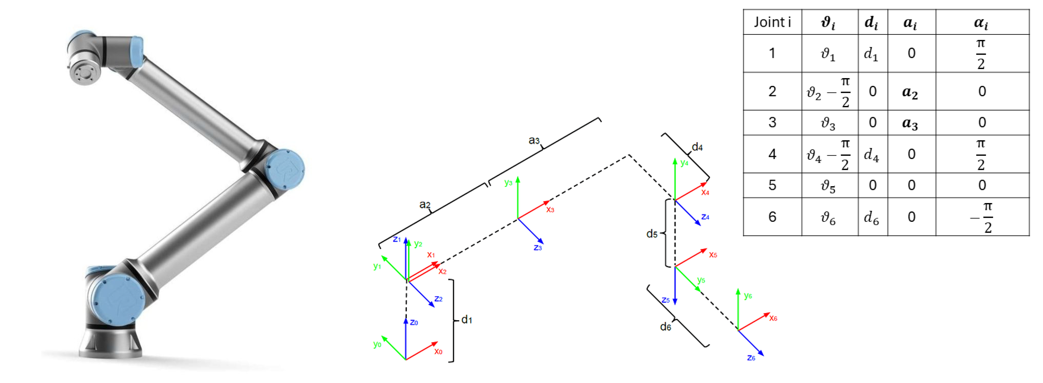
- ABB irb120The robot ABB irb120 is an open-chain industrial robot, characterized by a six-Degrees of Freedom (DOF) kinematic structure with six revolute joints [42], see Figure 5.
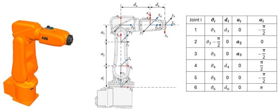 Figure 5. Robot ABB irb120, reference joint frames, and DH parameters.
 - Universal Robot 10 (UR10)The robot UR10 is a collaborative robot, characterized by a six-DOF kinematic structure with six revolute joints, see Figure 6. It needs to be specified that, in this case, a small adjustment of DH parameters was required in order to match the real robot model with the kinematic model of the simulation software.
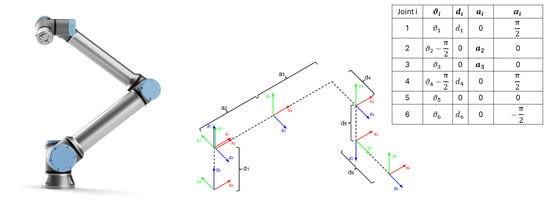 Figure 6. Robot UR10, reference joint frames, and DH parameters.
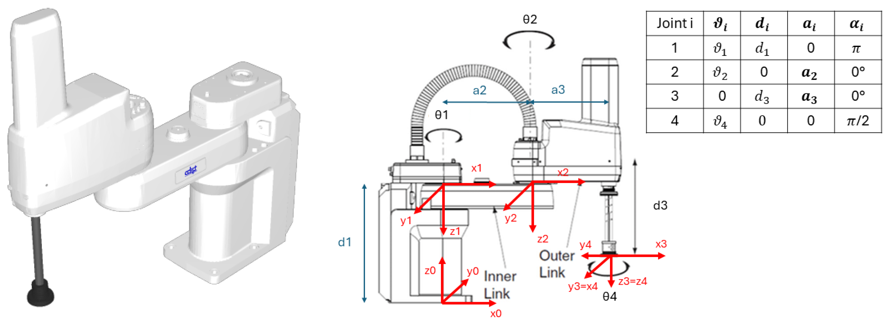
 - Adept SCARA Cobra e600The robot SCARA Cobra e600 is an open-chain industrial robot, characterized by a four-DOF kinematic structure with three revolute joints and one prismatic joint, see Figure 7. The same reasoning regarding DH parameters for the UR10 was applied also for this robot.
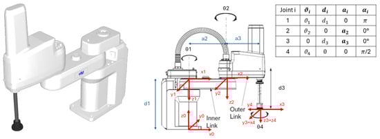 Figure 7. Robot Adept SCARA Cobra e600, reference joint frames, and DH parameters.While DH parameters are widely used for modeling open-chain manipulators, their application to closed-chain robotic systems is limited. The kinematic loops in such systems introduce constraints that cannot be easily represented by the sequential frame assignment of standard DH notation. Therefore, alternative approaches, such as constraint-based models or loop-closure equations, are typically used. For the closed-chain robots considered in this work, DH representations are omitted in favor of describing their kinematic structure and modeling approach.
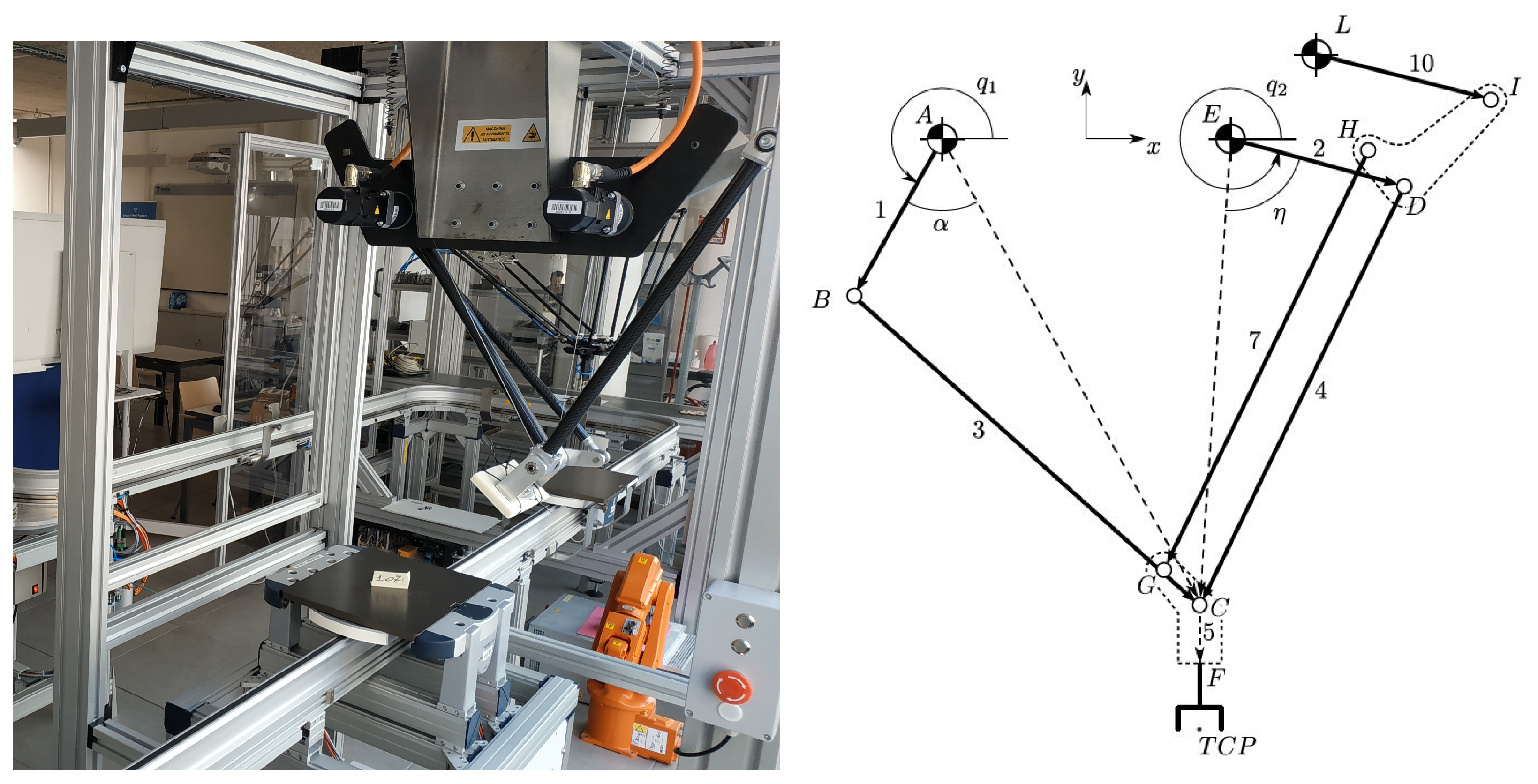
 - Adept OMRON QuattroThe robot Adept OMRON Quattro is a closed-chain industrial robot, characterized by a four-DOF kinematic structure with four constrained revolute joints, see Figure 8. The Quattro robot features four identical kinematic chains, each driven by a base-mounted rotary actuator. The inverse kinematics of the robot is derived through loop closure equations, as demonstrated in [43].
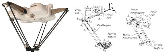 Figure 8. Robot Adept Omron Quattro, kinematic representation, and scheme of one leg chain.
 - Delta2 prototypeThe Delta2 robot represents the prototype of a closed-chain parallel robot manipulator, characterized by a kinematic structure with two revolute joints [44]. The Delta2 is a planar multibody system with two DOF where the end-effector is kinematically constrained to always have the same orientation, thanks to the parallelogram overstructure, as visible in Figure 9. Since this robot is a prototype, manufactured in-house for the laboratory in which it is installed, the position analysis of the Delta2 parallel robot was conducted by hand, and a personalized approach to simulate the kinematic chains’ constraints and movements in the simulation environment was adopted.
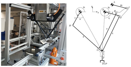 Figure 9. Delta2 prototype and kinematic representation.
4.3. Simulation Environment Setup
Among various simulation tools, this study employs industrialPhysics (iPhysics), version 3.5, developed by a German company, machineering GmbH & Co. KG [45]. iPhysics, due to its 3D physics-based engine, enables multibody kinematic modeling with detailed control over constraints such as translations and rotations. The platform supports static, kinematic, and dynamic objects, and its internal scripting language allows fine-grained manipulation of variables to model and control object behavior precisely. In this work, iPhysics is used to model a transfer line system, including switches, shuttles, and two manipulators. The resulting Digital Model (DM) aims to replicate the system layout and motion dynamics, as visualized in Figure 10.
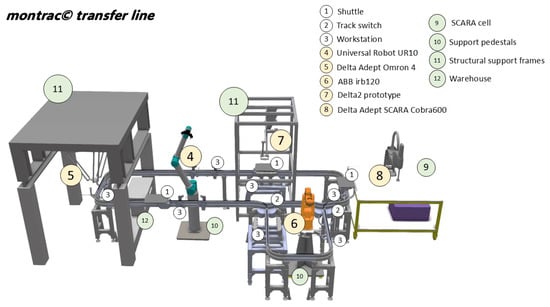
Figure 10.
Digital Model of the transfer line system in exam and mechatronic equipment in the environment of iPhysics.
Table 1 outlines the status of the modeled components within iPhysics.

Table 1.
Simulated mechatronic equipment overview.
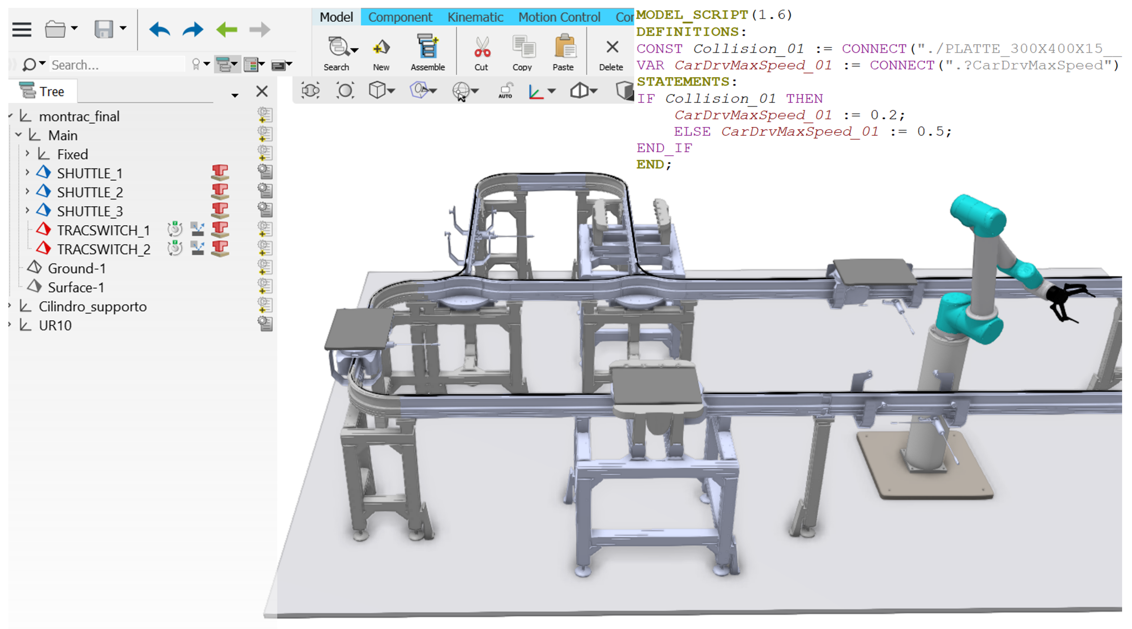
Accurate modeling of the mechatronic operations along the line is critical to ensure a reliable simulation-based DT infrastructure. The line’s structure and track rail paths have been implemented using three distinct sketches in the 3D space. A collision detection function is used to track shuttle presence on the switches, and a custom logic script governs shuttle behavior, routing them efficiently along the main track when outer ring workstations are not targeted. The passive switch aligns with the active one to maintain consistent routing.
The shuttle behavior, including movement along rails and coordination at workstations, builds on a previous kinematic model described in [39] and also in the previous subsection of this chapter. The control logic ensures precise synchronization between real and virtual systems. Braking and stopping behaviors before workstation entry are simulated using collision detection, allowing the virtual shuttles to mirror real-world timing and logic. Figure 11 illustrates the simulation structure in iPhysics, including the object tree and shuttle velocity control script.
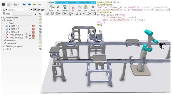
Figure 11.
Partial simulation setup of the DM in iPhysics environment.
For what concerns the robotic manipulators, the two important steps to be followed are the definition of their kinematic chain in the software and the exploitation of the communication protocols utilized by the DT architecture to read robots’ positions real-time and communicate them to iPhysics. In this way, the mere DM can be evolved into a DS, with the virtual mirroring the movements of the real one, and possibly into a full DT part, with the possibility to teach robot poses from the simulation environment of iPhysics directly to the physical manipulators. It is important to underline that each robot was kinematized and connected as a sole machine since every robot has a different controller and control interface. Two examples, for instance, are here described: the UR10 and the Adept SCARA Cobra e600.
Concerning the UR10, it is possible to exploit Universal Robot RTDE communication. RTDE communicates with the simulation environment available in the teach pendant of the real robot (URSim). This possibility has been investigated and integrated in the transfer line model: by matching the IP address of the real robot with the virtual one, an integrated script in the simulation reads the actual joints positions of the real robot and overwrites the associated variables in the DM. As a result, the virtual replica copies exactly the robot movements in almost real time. The outcome of the UR10 integration into the DM is proven by Figure 12. It is indeed visible that the virtual replica of the robot has assumed the same position with respect to the real robot.
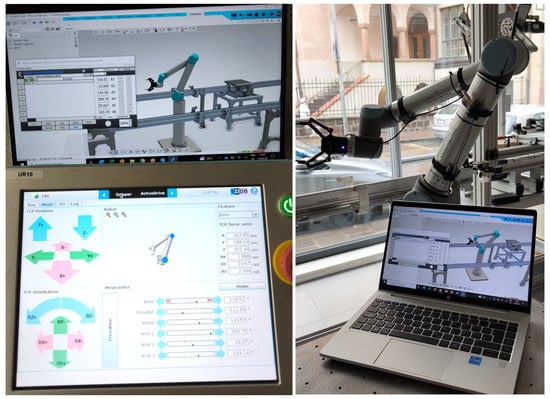
Figure 12.
On the left: Matching joint position values between iPhysics (up) and URSim (down); on the right: physical setup in the laboratory environment.
Regarding the Adept SCARA Cobra e600, the followed approach is slightly different. Since iPhysics does not integrate a direct plug-in to communicate with the robot control program, an external script file has been created and integrated in the DT architecture. Further details about how the communication works and which programming language has been utilized are reported in the next Section 4.3. The virtual robot is indeed capable of mirroring the real robot movements thanks to overwriting the joint values inside the simulation environment.
4.4. Data Flow Structuring
Data flow structuring is vital for seamless bidirectional real-time communication between the physical system and its digital twin (DT), enabling synchronized interactions among sensors, controllers, and simulations. Building on Section 3.2’s simulation-based multi-purpose layer concept, structured data flow supports the multi-scenario simulation strategy [46], allowing the DT to autonomously select optimal operational scenarios through continuous real-time sensor data and control commands exchange. This integration enhances decision-making and system efficiency by leveraging physics-based simulations [47]. Though often called “real-time,” data exchange is better viewed as near real time with inherent latency as true zero-latency remains unattainable in practice.
Specifically, the proposed DT architecture integrates both Object Twins and Process Twins to comprehensively represent the CPS in exam as case study. The physical layer comprises real-world mechatronic equipment producing (i) event-based messages and (ii) continuous telemetry data, transmitted via standardized protocols; here, MQTT is used. Despite MQTT’s limitations in latency and security, its simplicity suits early-stage, fast-deployment proof-of-concepts. The virtual (DT) layer integrates Object Twins by creating accurate digital replicas of individual mechatronic entities, effectively mirroring their operational behaviors and physical characteristics in the environment of the chosen software (iPhysics). Simultaneously, the DT layer encompasses Process Twins, managing operational sequences, workflows, and interactions among these entities. By orchestrating system data and operations, the DT layer centralizes control and task allocation, significantly enhancing system flexibility, although at the potential cost of increased complexity and cybersecurity considerations. The middle layer enables communication and interoperability by adapting data formats and protocols and managing entity presence and capabilities. Each component is wrapped with a semi-standardized interface toward the DT, allowing integration of diverse physical or digital entities with minimal effort. In this case, the middle layer integrates the physics-based iPhysics simulation into the DT framework (Figure 13), wrapping iPhysics, which is not natively designed for DT use, and enabling it to serve as both simulation engine and reasoning module. Communication between the DT layer and iPhysics is handled via REST APIs triggered by MQTT commands, ensuring smooth interaction across the architecture.
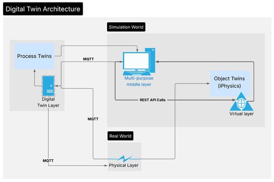
Figure 13.
Exemplary data flow for simulation-based digital twin architectures.
4.4.1. Simulation for Design Phase and Redesign
During the design phase, when the physical system is not yet available, it is common to create virtual representations at varying levels of detail, referred to as DMs. By virtualizing the control logic, the communication architecture can be structured so that physical components and simulation modules are interchangeable. This enables the controller to interact with the simulation as if it were the real system, sending commands and receiving feedback in a closed loop. Even when the system is already operational, this offline simulation technique allows for exploring alternative configurations, reducing commissioning time and de-risking deployment [48].
4.4.2. Simulation for Optimization
Once the physical system becomes operational, the DT infrastructure can be leveraged for process optimization. Maintaining the same virtualized control configuration, the DT exploits the asynchronous time domains of the real and virtual environments, where the latter can operate faster than real time. Commands intended for the physical system are first evaluated in the simulation module, which rapidly explores alternative scenarios to identify parameter configurations that optimize specific KPIs. The optimized instructions are then sent back and executed by the physical system. Repeating this loop enables continuous, data-driven self-optimization of cyber–physical production systems (CPPSs).
4.4.3. Simulation for Validation
Lastly, the physics-based simulation module can operate in parallel with the physical system. The virtual controller sends identical commands to both environments, enabling synchronous execution. In this configuration, the simulation acts as a high-fidelity digital replica, modeling the system’s ideal behavior. By observing and comparing task execution in both domains, the system can identify deviations, inefficiencies, or anomalies. These insights may support human decision-making in critical scenarios or feed into automated self-optimization routines, as described in the previous case.
Simulation for design/redesign, optimization, and validation are not isolated elements within the DT environment; rather, their combined use significantly enhances DT capabilities. In particular, the optimization and validation simulations can be tightly integrated, forming a robust feedback loop that continuously refines overall system control. Here, the “system” refers to the set of elements within the DT’s scope, ranging from a single machine enclosure to a production line, an entire shopfloor, or even a complete supply chain.
5. Results and Discussion
The DT framework was preliminarily validated through test runs focusing on shuttle movements and velocity adjustments. Visual comparisons between simulation and real-world behavior showed promising alignment, though the lack of real-time sensor feedback and precise acceleration data limits full dynamic validation for the whole shuttle movement. The shuttles, indeed, give feedback just as they depart from a workstation and as they arrive in the one they have been sent, not for the whole rail path inbetween. Precise dynamic tracking along the rail path is considered part of the future work. Communication delays may also affect real-time synchronization and simulation accuracy.
To assess the multipurpose layer’s performance, several tests evaluated the simulation environment’s computational efficiency. The iPhysics simulation used a 0.01 s time step for numerical integration and logged data every fourth step (0.04 s) to balance data resolution and redundancy. The simulation ran at 25 frames per second, ensuring smooth visualization without impacting physical event resolution. An internal profiling tool measured execution times in milliseconds across three phases (A. pre-processing, B. run-time, and C. post-processing), helping to identify computational bottlenecks and evaluate scalability. As a result, task durations were evaluated and compared. All simulations were performed on a mobile workstation equipped with an 11th Gen Intel® Core™ i5-1135G7 processor running at 2.40 GHz (quad-core with 8 threads) and 32GB of RAM. The device operates on a 64-bit Windows system (x 64-based architecture) and features integrated Intel Iris Xe Graphics. While not equipped with a discrete GPU, the system supports multitouch input and was sufficient for executing real-time 3D physics-based simulations with moderate computational complexity.
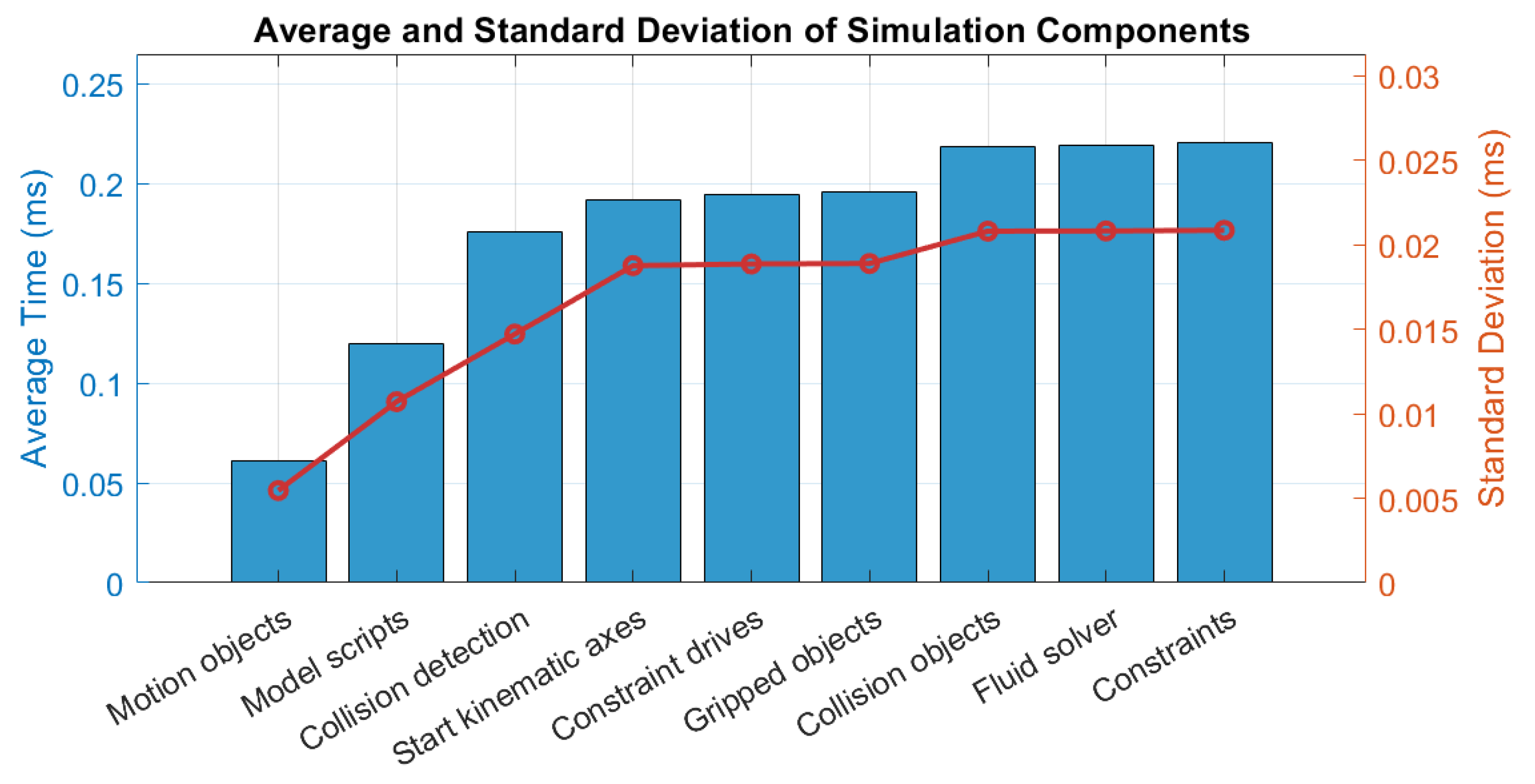
- Pre-processing phaseThis phase involves preparation steps before the actual physics calculations begin. It includes initializing motion objects, running model scripts, activating kinematic axes, etc. Table 2 reports a sample of task durations for a standard simulation where only the shuttles were controlled and moved.
Table 2. Sample task duration (in ms) in the pre-processing phase.By further evaluating pre-processing operations, it is evident that they can be considered lightweight, averaging between 0.06 ms and 0.22 ms, with minimal variability (standard deviations below 0.02 ms), as shown in Figure 14.
 Figure 14. Average and standard deviation values for pre-processing operations.
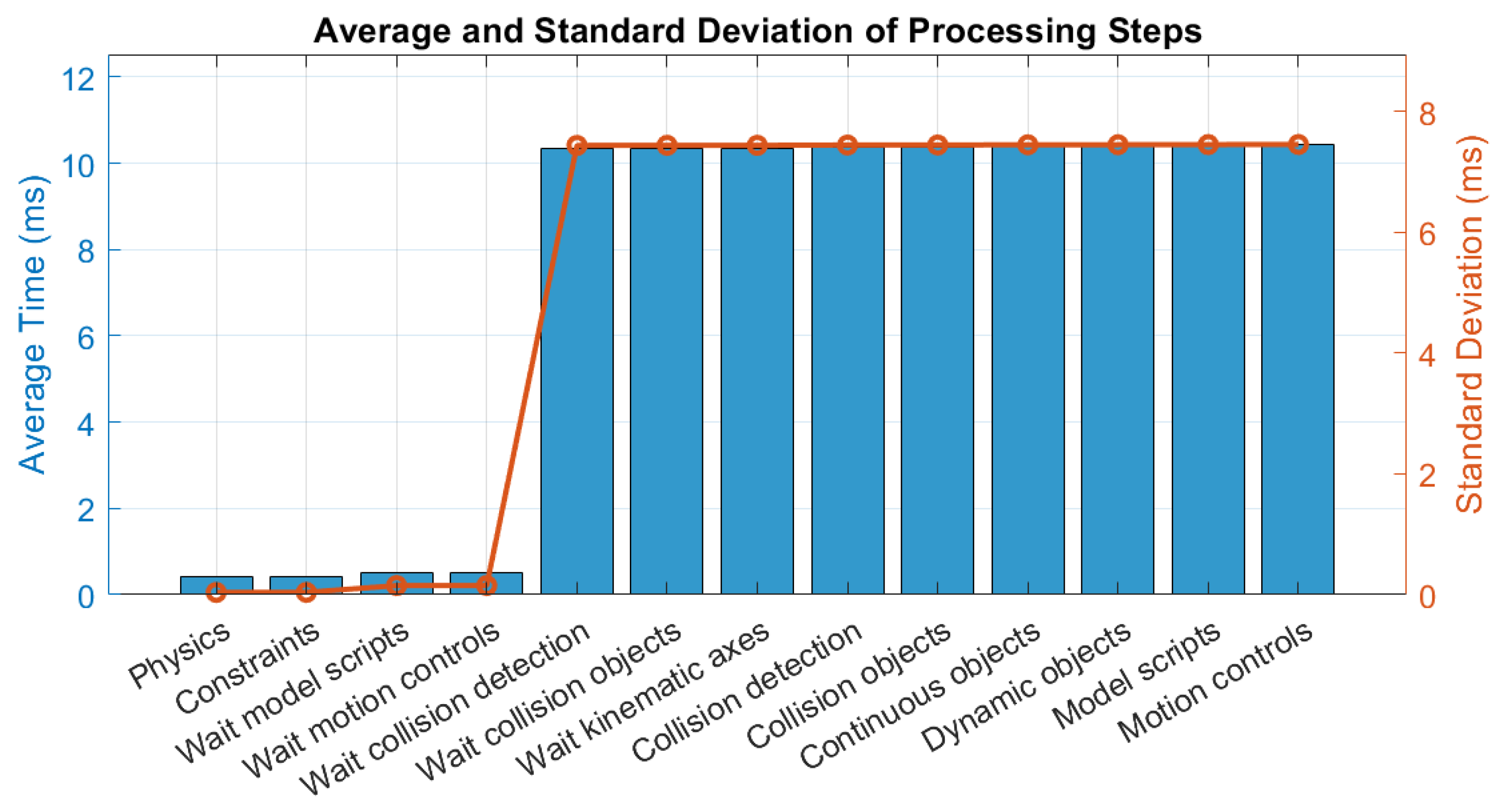
 - Run-Time PhaseThe run-time phase encompasses the physics engine and its coordination with model components. The profiling tool logs both active physics computation and synchronization delays (i.e., wait times for various sub-processes to complete). Also, for this phase, a sample table of task durations and the results of average and standard deviation are reported in Table 3 and Figure 15.
Table 3. Sample task duration (in ms) in the run-time phase.
 Figure 15. Average and standard deviation values for run-time operations.The most significant time costs were associated with waiting operations for the coordination among the different components, like kinematic axes (an average of 10.345 ms and standard deviation of 7.437 ms), motion controls (an average of 10.340 ms and standard deviation of 7.436 ms), or model scripts (an average of 10.339 ms and standard deviation of 7.436 ms). These values suggest that the synchronization or data transfer latencies dominates the run-time cost, likely due to multithreading or communication overhead between simulation modules. Pure physics solving times (e.g., physics: 0.429 ms) are comparatively low, indicating that raw computational load is not the primary bottleneck, rather, coordination among components is, as previously said.
 - Post-processing phaseIn this final phase, the simulation updates positions, sensors, and graphical or logical state after solving the dynamics. Also, for this phase, a sample table of task durations and the results of average and standard deviation are reported in Table 4 and Figure 16, respectively. The plot in Figure 16 has been rescaled to obtain a better visualization.
Table 4. Sample task duration (in ms) in the post-processing phase.
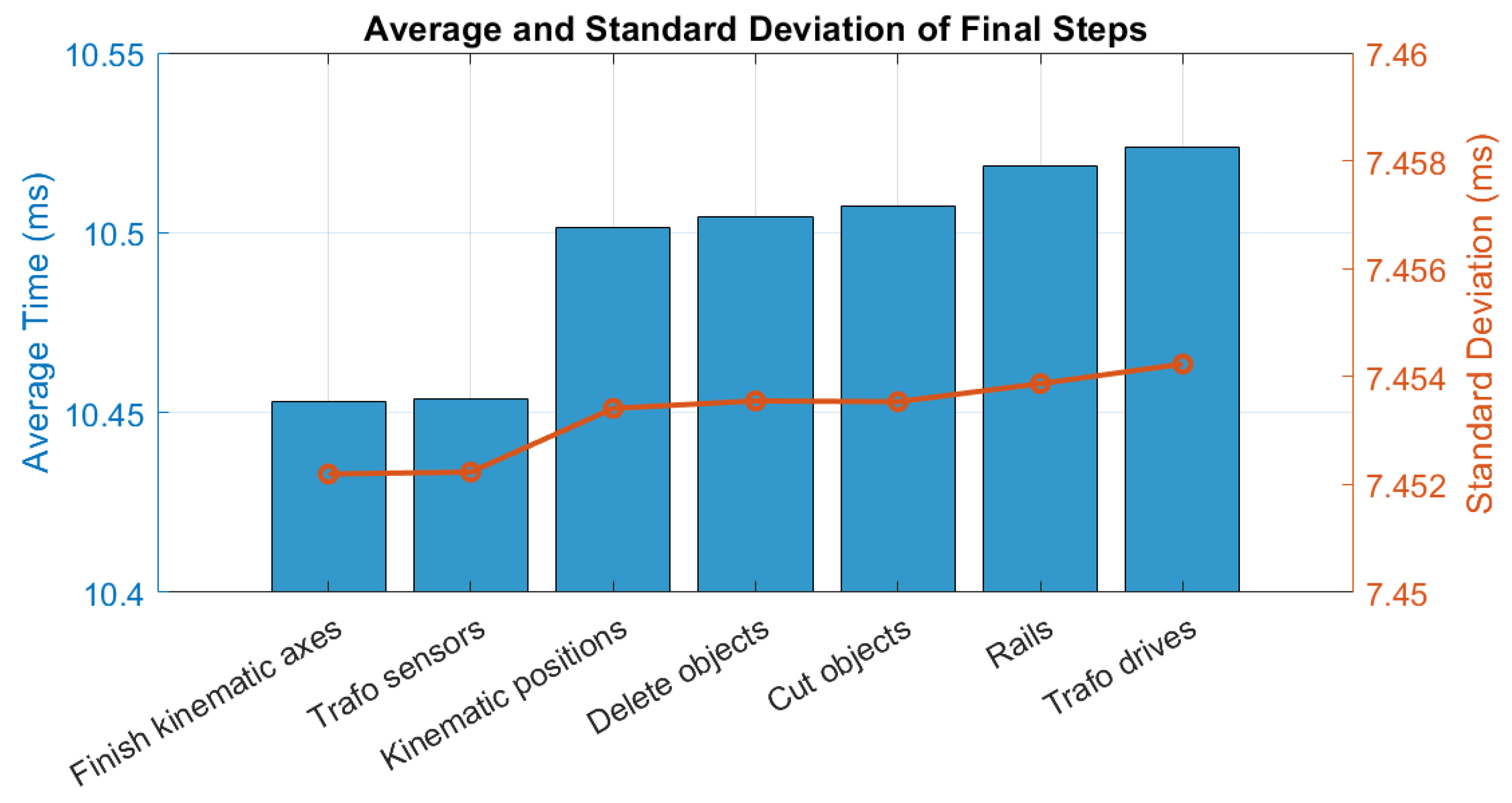
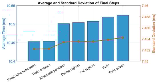 Figure 16. Average and standard deviation values for post-processing operations.Key processes and their average durations include the end setup of kinematic axes (an average of 10.519 ms and standard deviation of 7.454 ms), of trafo sensors (an average of 10.524 ms and standard deviation of 7.454 ms), and of kinematic positions (an ave-age of 10.539 ms and standard deviation of 7.455 ms). Again, the high variability points to possible dependency chains that force components to wait for others to complete.
The average simulation time per step is about 10 ms, matching the 0.01 s time step and indicating near-real-time performance. However, large standard deviations (up to 7.45 ms) in run-time and post-processing suggest non-deterministic delays from varying object interactions and asynchronous scripts. Pre-processing times are minimal, so model initialization is not a bottleneck. Optimization should target reducing waiting times and synchronization overhead to boost scalability and efficiency, potentially via more powerful hardware or improved data protocols.
Currently, the simulation uses shuttle parameters from production sheets, lacking real-time adjustments based on system performance. Modeling shuttle acceleration/deceleration at specific rail locations, mimicking physical pads under the track, would improve realism and accuracy. Planned improvements aim to address these gaps through the following:
- Precise Modeling of Acceleration/Deceleration Points—By integrating the physical pads into the virtual environment, the DT will better replicate real-world motion dynamics.
- Sensor Integration for Real-Time Validation—Installing velocity, acceleration, and position sensors on the shuttles will allow for real-time data collection, enhancing the accuracy of the DT model.
- Optimization of System Latency—Exploring computational improvements and network optimizations to reduce time delays and improve real-time control capabilities.
While the decision-making layer is not yet implemented, its conceptual design highlights its potential benefits. The envisioned framework will utilize a simulation-based reasoning approach, where different operational scenarios are tested within the DT. Based on the simulation results, the multi-purpose layer will evaluate key parameters such as productivity, efficiency, and energy consumption to autonomously select and execute the optimal scenario. For instance, the decision-making layer will be responsible of dynamic task dispatching for the assembly operation thought to be setup as principal operation of the transfer line. Based on parallel simulation results, the decision-making layer will indeed decide, i.e., which shuttle to send to which workstation, which robot to activate in order to perform that specific operation and which task sequence will be the optimal to assemble the final desired product. Once integrated, this approach is expected to (a) enhance decision-making by preemptively testing process variations; (b) optimize energy consumption by identifying the most efficient robot and shuttle operations; (c) reduce downtime and inefficiencies through real-time adjustments based on sensor feedback and AI-driven insights.
Regarding system latency, while the current levels identified through preliminary testing have proven satisfactory and acceptable for the initial scope of this study, future developments will include practical strategies aimed at further latency reduction, which can be critical for such applications in CPSs [49]. Specifically, we plan to explore computational enhancements, such as optimizing message payloads, adopting more efficient serialization methods like Protocol Buffers, and investigating alternative communication protocols (e.g., WebSockets). Additionally, integrating edge computing solutions is considered a viable strategy to bring computational resources closer to the physical devices, thereby significantly minimizing network-induced delays and improving overall real-time control performance. An improvement of the hardware components to run the simulation tests is also planned, and this will for sure result in a better system overall performance.
6. Conclusions
This work explores the role of decision-oriented multi-purpose layer in Digital Twin (DT) architectures, with a specific focus on simulation-based reasoning for decision-making and optimization. The multi-purpose layer is usually conceptualized as a key component within a DT framework, enabling predictive analytics, scenario evaluation, and autonomous system adaptation. Firstly, an insight into peculiar DT architectures and common practices for the development and exploitation of decision-oriented layers are analyzed. One of these techniques is based on exploiting simulation for testing and optimizing operational scenarios especially for mechatronic multi-machine industrial systems. In particular, by leveraging physics-based simulations, the proposed approach aims to enhance real-time decision-making in industrial cyber–physical systems.
To illustrate the practical application of this framework, a small-scale transfer line in a laboratory environment has been presented as a case study. The modeling of system components, including moving shuttles and interacting machines, has been detailed, highlighting challenges related to real-time synchronization, parameter validation, and computational constraints. While preliminary results show promising alignment between simulated and real-world behavior, further refinements are necessary to enhance the accuracy and responsiveness of the DT model.
Moreover, preliminary profiling of the simulation environment using iPhysics highlighted the importance of computational performance in real-time Digital Twin applications. The analysis revealed that the most significant delays occurred during the run-time and post-processing phases, where synchronization and coordination among simulation modules introduced measurable latency. Despite these challenges, the overall simulation remained within real-time constraints, with step durations aligning closely to the configured simulation time step of 0.01 s. These findings reinforce the feasibility of integrating high-fidelity simulations into decision-oriented DT layers while also emphasizing the need for optimization in multi-threaded execution and module communication to improve responsiveness and scalability.
The next steps of this research involve the implementation of the layer, which will
- Utilize simulation-driven optimization to evaluate multiple operational scenarios.
- Select the most efficient configuration based on productivity, energy consumption, and process efficiency (given parallel simulation results).
- Enable adaptive control by dynamically adjusting system parameters.
While the decision-making layer remains conceptual at present, its strategic design emphasizes substantial potential benefits for future implementation. The simulation-driven reasoning approach proposed in this work offers a structured framework for testing diverse operational scenarios virtually, thus enabling informed and autonomous decisions regarding task allocation, shuttle routing, robot utilization, and optimal assembly sequences. By evaluating critical parameters like productivity, efficiency, and energy consumption through parallel simulation runs, the decision-making layer is anticipated to markedly improve operational performance. Specifically, its integration promises enhanced decision quality via preemptive scenario analysis, increased energy efficiency by optimizing machinery operations, and reduced downtime through nearly real-time adjustments. Future research will focus on validating the proposed framework through expanded case studies, assessing its scalability, and refining its integration with real-time data acquisition and control systems. A possible adaptation to other systems in the same laboratory or the eventual inclusion of more machines operating along the line into the DT layer will be also explored.
Author Contributions
C.N. and M.D.M. jointly contributed to the conceptualization, literature review, methodology development, and writing of the manuscript. They also took care of the experimental setup, simulation modeling, and data analysis. R.V. and E.R. provided supervision, critical revisions, and guidance throughout the research process, ensuring the scientific validity and alignment of the work within the broader field of Digital Twin applications in mechatronics and manufacturing systems. All authors have read and agreed to the published version of the manuscript.
Funding
This paperwork falls within the research activities of the project “A Strategic Roadmap Toward the Next Level of Intelligent, Sustainable, and Human-Centered SME: SME 5.0” from the European Union’s Horizon 2021 research and innovation program under the Marie Skłodowska-Curie Grant agreement No. 101086487.
Data Availability Statement
The raw data supporting the conclusions of this article will be made available by the authors on request.
Conflicts of Interest
The authors declare no conflicts of interest. Moreover, the funders had no role in the design of the study; in the collection, analyses, or interpretation of data; in the writing of the manuscript; or in the decision to publish the results.
References
- Stavropoulos, P.; Papacharalampopoulos, A.; Sabatakakis, K.; Mourtzis, D. Meta-modelling of manufacturing processes and automation workflows towards designing and operating digital twins. Appl. Sci. 2023, 13, 1945. [Google Scholar] [CrossRef]
- Zhu, X.; Zhao, Q.; Yao, X. How inventory flexibility affects productivity: The moderating roles of digital transformation and supply chain concentration. J. Manuf. Technol. Manag. 2024, 35, 1554–1580. [Google Scholar] [CrossRef]
- Lehner, C.; Padovano, A.; Zehetner, C.; Hackenberg, G. Digital twin and digital thread within the product lifecycle management. Procedia Comput. Sci. 2024, 232, 2875–2886. [Google Scholar] [CrossRef]
- Haricha, K.; Khiat, A.; Issaoui, Y.; Bahnasse, A.; Ouajji, H. Recent technological progress to empower smart manufacturing: Review and potential guidelines. IEEE Access 2023, 11, 77929–77951. [Google Scholar] [CrossRef]
- Wang, B.; Tao, F.; Fang, X.; Liu, C.; Liu, Y.; Freiheit, T. Smart manufacturing and intelligent manufacturing: A comparative review. Engineering 2021, 7, 738–757. [Google Scholar] [CrossRef]
- Tao, F.; Xiao, B.; Qi, Q.; Cheng, J.; Ji, P. Digital twin modeling. J. Manuf. Syst. 2022, 64, 372–389. [Google Scholar] [CrossRef]
- VanDerHorn, E.; Mahadevan, S. Digital Twin: Generalization, characterization and implementation. Decis. Support Syst. 2021, 145, 113524. [Google Scholar] [CrossRef]
- Goodwin, T.; Xu, J.; Celik, N.; Chen, C.H. Real-time digital twin-based optimization with predictive simulation learning. J. Simul. 2024, 18, 47–64. [Google Scholar] [CrossRef]
- Nezzi, C.; Gufler, V.; Vidoni, R.; Rauch, E. Kinematic and Dynamic Modeling of Mechanical Systems towards Digital Twins. Results Eng. 2025, 26, 104874. [Google Scholar] [CrossRef]
- Dosoftei, C.C. Simulation power vs. immersive capabilities: Enhanced understanding and interaction with digital twin of a mechatronic system. Appl. Sci. 2023, 13, 6463. [Google Scholar] [CrossRef]
- Usman, S.; Lu, C.; Gao, G. Flexible job-shop scheduling with limited flexible workers using an improved multiobjective discrete teaching–learning based optimization algorithm. Optim. Eng. 2024, 25, 1237–1270. [Google Scholar] [CrossRef]
- Rathore, M.M.; Shah, S.A.; Shukla, D.; Bentafat, E.; Bakiras, S. The role of AI, machine learning, and big data in digital twinning: A systematic literature review, challenges, and opportunities. IEEE Access 2021, 9, 32030–32052. [Google Scholar] [CrossRef]
- Hakiri, A.; Gokhale, A.; Yahia, S.B.; Mellouli, N. A comprehensive survey on digital twin for future networks and emerging Internet of Things industry. Comput. Netw. 2024, 244, 110350. [Google Scholar] [CrossRef]
- Hu, S.; Li, C.; Li, B.; Yang, M.; Wang, X.; Gao, T.; Xu, P. Digital twins enabling intelligent manufacturing: From methodology to application. Intell. Sustain. Manuf. 2024, 1, 10007. [Google Scholar] [CrossRef]
- Wang, H.; Yang, Z.; Zhang, Q.; Sun, Q.; Lim, E. A digital twin platform integrating process parameter simulation solution for intelligent manufacturing. Electronics 2024, 13, 802. [Google Scholar] [CrossRef]
- Kritzinger, W.; Karner, M.; Traar, G.; Henjes, J.; Sihn, W. Digital Twin in manufacturing: A categorical literature review and classification. IFAC-PapersOnLine 2018, 51, 1016–1022. [Google Scholar] [CrossRef]
- Ghosh, A.K.; Ullah, A.S.; Teti, R.; Kubo, A. Developing sensor signal-based digital twins for intelligent machine tools. J. Ind. Inf. Integr. 2021, 24, 100242. [Google Scholar] [CrossRef]
- Miller, A.M.; Alvarez, R.; Hartman, N. Towards an extended model-based definition for the digital twin. Comput.-Aided Des. Appl. 2018, 15, 880–891. [Google Scholar] [CrossRef]
- Lee, Y.; Baek, M.S.; Yoon, K. Digital Entity Management Methodology for Digital Twin Implementation: Concept, Definition, and Examples. IEEE Trans. Broadcast. 2025, 71, 19–29. [Google Scholar] [CrossRef]
- Jeong, D.Y.; Baek, M.S.; Lim, T.B.; Kim, Y.W.; Kim, S.H.; Lee, Y.T.; Jung, W.S.; Lee, I.B. Digital twin: Technology evolution stages and implementation layers with technology elements. IEEE Access 2022, 10, 52609–52620. [Google Scholar] [CrossRef]
- Rossmann, A.; Hertweck, D. Digital twins: A meta-review on their conceptualization, application, and reference architecture. In Proceedings of the 55th Hawaii International Conference on System Sciences (HICSS 2022), Virtual Event/Maui, HI, USA, 4–7 January 2022; pp. 4518–4527. [Google Scholar]
- Aheleroff, S.; Xu, X.; Zhong, R.Y.; Lu, Y. Digital twin as a service (DTaaS) in Industry 4.0: An architecture reference model. Adv. Eng. Inform. 2021, 47, 101225. [Google Scholar] [CrossRef]
- Gehrmann, C.; Gunnarsson, M. A digital twin based industrial automation and control system security architecture. IEEE Trans. Ind. Inform. 2019, 16, 669–680. [Google Scholar] [CrossRef]
- ISO 23247-1:2021; Automation Systems and Integration, Digital Twin Framework for Manufacturing. International Organization for Standardization: Geneva, Switzerland, 2021.
- Răileanu, S.; Borangiu, T.; Ivănescu, N.; Morariu, O.; Anton, F. Integrating the digital twin of a shop floor conveyor in the manufacturing control system. In Service Oriented, Holonic and Multi-Agent Manufacturing Systems for Industry of the Future: Proceedings of SOHOMA 2019 9; Springer International Publishing: Berlin/Heidelberg, Germany, 2020; pp. 134–145. [Google Scholar]
- Borangiu, T.; Oltean, E.; Răileanu, S.; Anton, F.; Anton, S.; Iacob, I. Embedded digital twin for ARTI-type control of semi-continuous production processes. In Service Oriented, Holonic and Multi-Agent Manufacturing Systems for Industry of the Future: Proceedings of SOHOMA 2019 9; Springer International Publishing: Berlin/Heidelberg, Germany, 2020; pp. 113–133. [Google Scholar]
- Alam, K.M.; Saddik, A.E. C2PS: A digital twin architecture reference model for the cloud-based cyber-physical systems. IEEE Access 2017, 5, 2050–2062. [Google Scholar] [CrossRef]
- Redelinghuys, A.J.H.; Basson, A.H.; Kruger, K. A six-layer architecture for the digital twin: A manufacturing case study implementation. J. Intell. Manuf. 2020, 31, 1383–1402. [Google Scholar] [CrossRef]
- Alexopoulos, K.; Nikolakis, N.; Chryssolouris, G. Digital twin-driven supervised machine learning for the development of artificial intelligence applications in manufacturing. Int. J. Comput. Integr. Manuf. 2020, 33, 429–439. [Google Scholar] [CrossRef]
- Cronrath, C.; Aderiani, A.R.; Lennartson, B. Enhancing digital twins through reinforcement learning. In Proceedings of the 2019 IEEE 15th International Conference on Automation Science and Engineering (CASE), Vancouver, BC, Canada, 22–26 August 2019; pp. 293–298. [Google Scholar]
- Salazar, W.C.; Machado, D.O.; Len, A.J.G.; Gonzalez, J.M.E.; Alba, C.B.; de Andrade, G.A.; Normey-Rico, J.E. Neuro-fuzzy digital twin of a high temperature generator. IFAC-PapersOnLine 2022, 55, 466–471. [Google Scholar] [CrossRef]
- Nezzi, C.; Marchi, M.D.; Aruväli, T.; Vidoni, R.; Rauch, E. Modeling and simulation of mechatronics equipment for a Digital Twin-enabled demonstrator. In Proceedings of the 10th International Conference on Control, Decision and Information Technologies (CoDIT), Vallette, Malta, 1–4 July 2024; pp. 2526–2529. [Google Scholar]
- Schluse, M.; Rossmann, J. From simulation to experimentable digital twins: Simulation-based development and operation of complex technical systems. In Proceedings of the 2016 IEEE International Symposium on Systems Engineering (ISSE), Edinburgh, UK, 3–5 October 2016; pp. 1–6. [Google Scholar]
- Nezzi, C.; Fink, S.; Rauch, E.; Vidoni, R. Digital Twin-Oriented Kinematic Modelling of a Large-Sized Mesh Welding Plant for Productivity Evaluation: A Company Case Study. In Proceedings of the IFToMM Symposium on Mechanism Design for Robotics, Timişoara, Romania, 27–29 June 2024; pp. 424–432. [Google Scholar]
- Phanden, R.K.; Sharma, P.; Dubey, A. A review on simulation in digital twin for aerospace, manufacturing and robotics. Mater. Today Proc. 2021, 38, 174–178. [Google Scholar] [CrossRef]
- Gualtieri, L.; Rojas, R.; Carabin, G.; Palomba, I.; Rauch, E.; Vidoni, R.; Matt, D.T. Advanced automation for SMEs in the I4.0 revolution: Engineering education and em-ployees training in the smart mini factory laboratory. In Proceedings of the 2018 IEEE International Conference on Industrial Engineering and Engineering Management, Bangkok, Thailand, 16–19 December 2018; pp. 1111–1115. [Google Scholar]
- Nezzi, C.; De Marchi, M.; Manzardo, M.; Galli, D.; Gualtieri, L.; Rauch, E.; Vidoni, R. Fostering Mechanisms, Mechatronics and Robotics Education in the Smart Mini Factory Laboratory of the Free University Of Bozen-Bolzano (I). In Proceedings of the Jc-IFToMM International Symposium, Kitakyushu, Japan, 22–23 June 2024; Volume 7, pp. 135–141. [Google Scholar]
- Wagner, M.G.; Ravani, B. Curves with rational Frenet-Serret motion. Comput. Aided Geom. Des. 1997, 15, 79–101. [Google Scholar] [CrossRef]
- Nezzi, C.; De Marchi, M.; Vidoni, R.; Rauch, E. Towards Real-Time Validation of Rail-Guided Shuttles: A Multibody Modelling and Digital Twin Approach. In Proceedings of the International Design Engineering Technical Conferences and Computers and Information in Engineering Conference. American Society of Mechanical Engineers, Washington, DC, USA, 25–28 August 2024; Volume 88438, p. V009T09A008. [Google Scholar]
- Corke, P. A simple and systematic approach to assigning Denavit–Hartenberg parameters. IEEE Trans. Robot. 2007, 23, 590–594. [Google Scholar] [CrossRef]
- Dikmeli, S. Forward & Inverse Kinematics solution of 6-DOF robots those have offset & spherical wrists. Eurasian J. Sci. Eng. Technol. 2022, 3, 14–28. [Google Scholar] [CrossRef]
- Li, Y.; Wang, Z.; Yang, H.; Zhang, H.; Wei, Y. Energy-optimal planning of robot trajectory based on dynamics. Arab. J. Sci. Eng. 2023, 48, 3523–3536. [Google Scholar] [CrossRef]
- Rosenzveig, V.; Briot, S.; Martinet, P. Minimal representation for the control of the Adept Quattro with rigid platform via leg observation considering a hidden robot model. In Proceedings of the 2013 IEEE/RSJ International Conference on Intelligent Robots and Systems, Tokyo, Japan, 3–7 November 2013; pp. 430–435. [Google Scholar]
- Carabin, G.; Palomba, I.; Wehrle, E.; Vidoni, R. Energy expenditure minimization for a delta-2 robot through a mixed approach. In Multibody Dynamics 2019: Proceedings of the 9th ECCOMAS Thematic Conference on Multibody Dynamics; Springer: Berlin/Heidelberg, Germany, 2020; pp. 383–390. [Google Scholar]
- Machineering. iPhysics. Available online: https://www.machineering.com/en/products/iphysics/ (accessed on 14 July 2025).
- Li, H.; Yan, P.; Zhou, H.; Pei, J.; Wang, B. Multi-Scenario Model Fusion and Verification Method for Digital Twin Machine Tool. J. Ind. Inf. Integr. 2025, 46, 100859. [Google Scholar] [CrossRef]
- Strahilov, A.; Ovtcharova, H.J.; Bär, T. Development of the physics-based assembly system model for the mechatronic valida-tion of automated assembly systems. In Proceedings of the 2012 Winter Simulation Conference (WSC), Berlin, Germany, 9–12 December 2012; pp. 1–11. [Google Scholar]
- Nezzi, C.; Muzhichkov, A.; Vidoni, R.; Rauch, E. Virtual commissioning of a mechatronic plant for insulating material processing: A company application towards Digital Twin. Procedia Comput. Sci. 2025, 253, 384–392. [Google Scholar] [CrossRef]
- Kiesel, R.; Jakob, F.; Vollmer, T.; Schmitt, R.H. Evaluation of ICT for Networked Control Systems of Latency-Critical Applications in Production. Procedia CIRP 2022, 112, 238–243. [Google Scholar] [CrossRef]


Disclaimer/Publisher’s Note: The statements, opinions and data contained in all publications are solely those of the individual author(s) and contributor(s) and not of MDPI and/or the editor(s). MDPI and/or the editor(s) disclaim responsibility for any injury to people or property resulting from any ideas, methods, instructions or products referred to in the content. |
© 2025 by the authors. Licensee MDPI, Basel, Switzerland. This article is an open access article distributed under the terms and conditions of the Creative Commons Attribution (CC BY) license (https://creativecommons.org/licenses/by/4.0/).