

An Influence Analysis of the Bearing Waviness on the Vibrations of a Flexible Gear


Abstract
1. Introduction
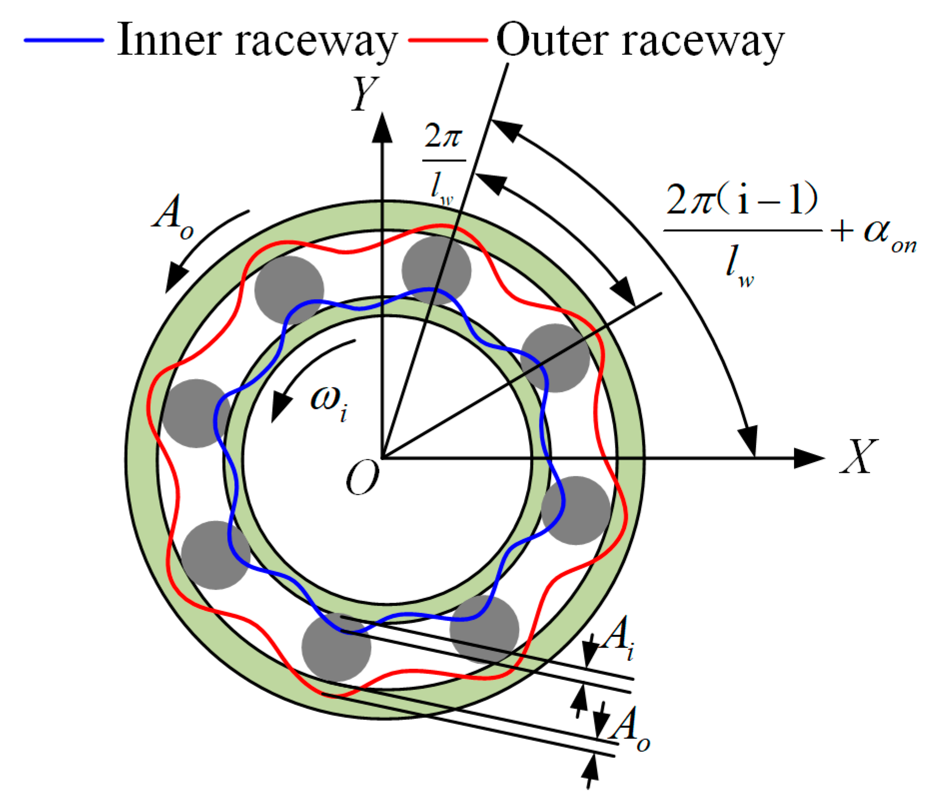
2. Dynamic Model of the Bearing with Uneven Waviness
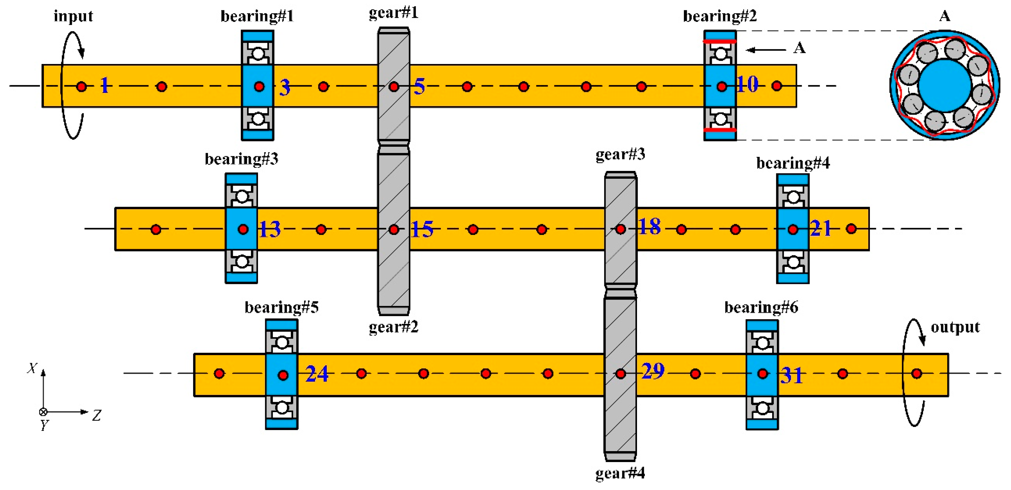
3. Dynamic Model of a Flexible Gear System with Waviness
4. Results and Discussions
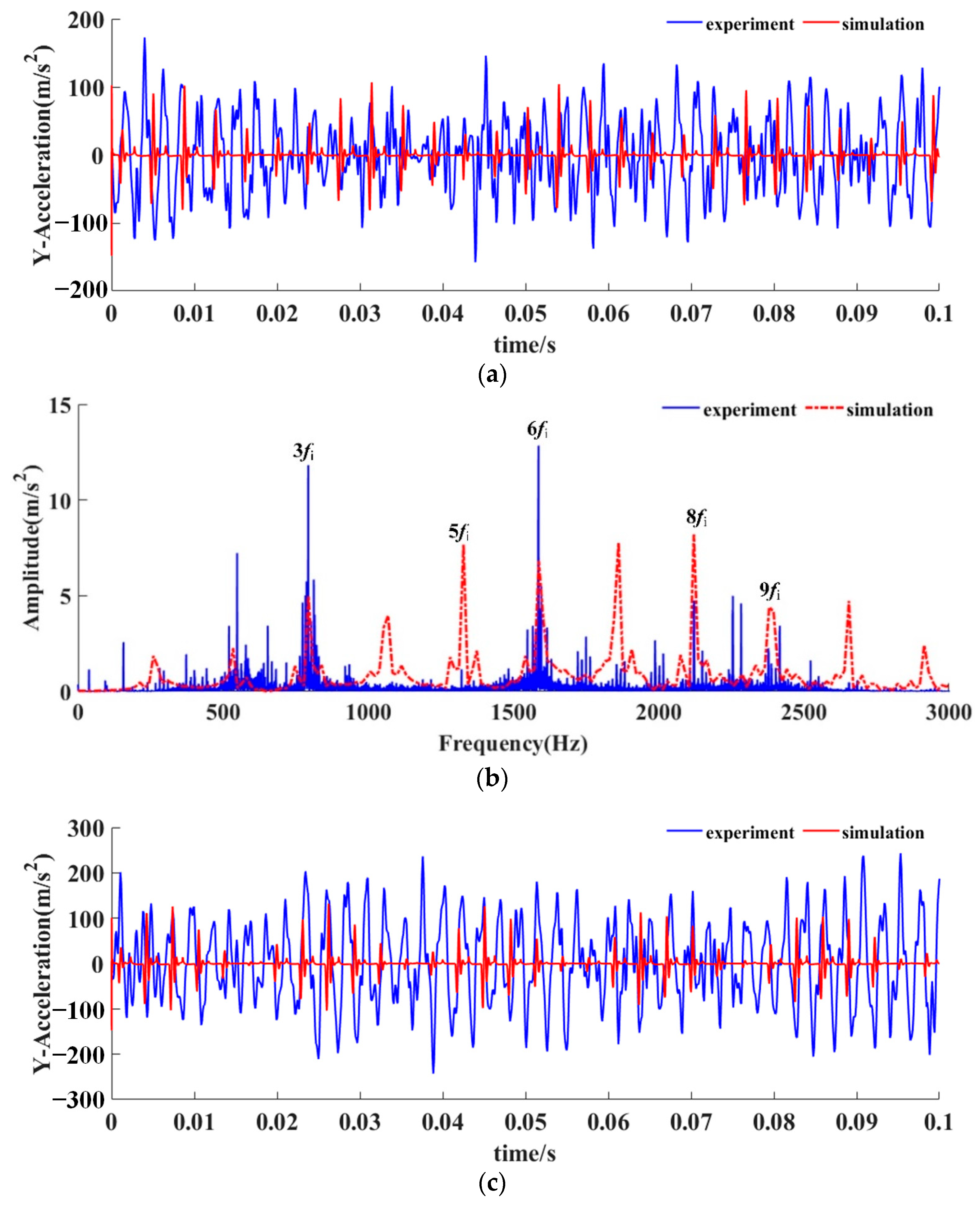
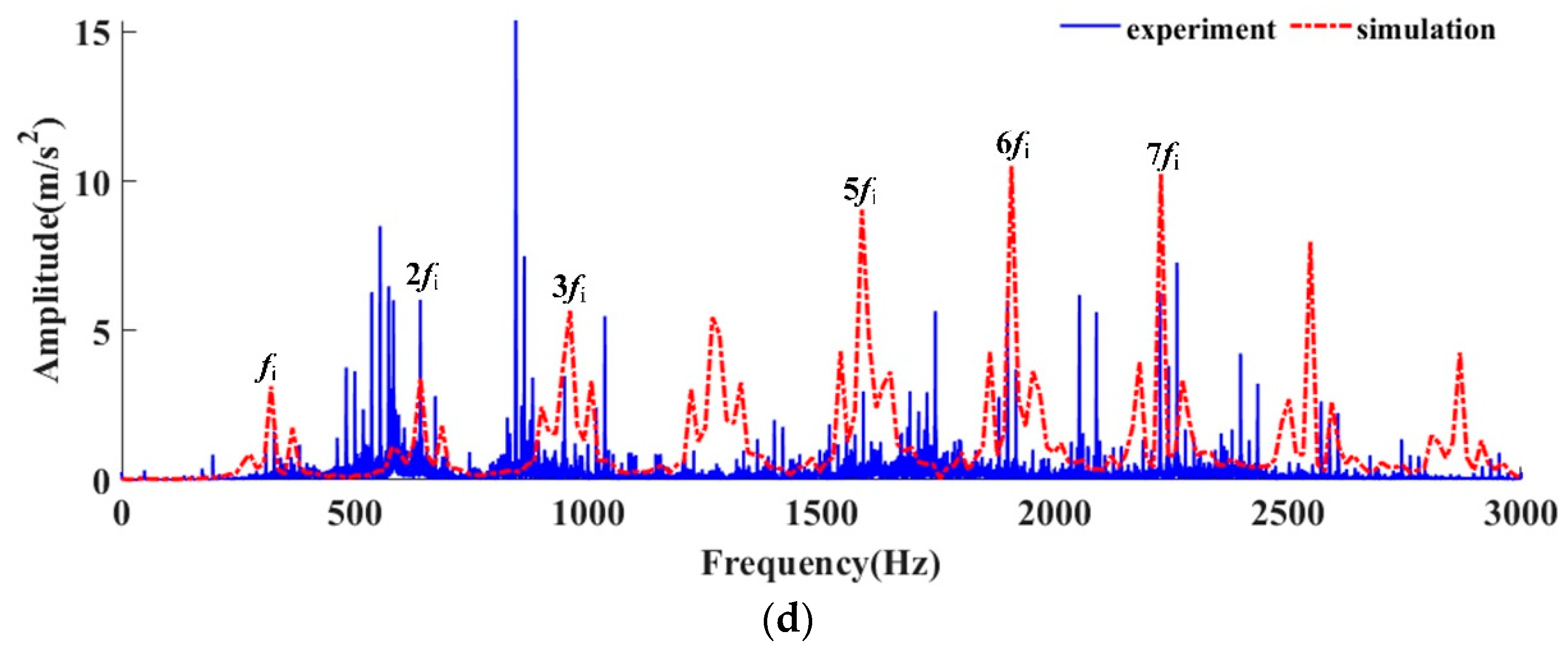
5. Experimental Validation
6. Conclusions
- (1)
- During the modeling process of bearing waviness, it was necessary to consider the unevenness of waviness on the raceway. The SWMS considers the time-variant contact stiffness and displacements could effectively obtain more accurate results, which should be closer to the actual results.
- (2)
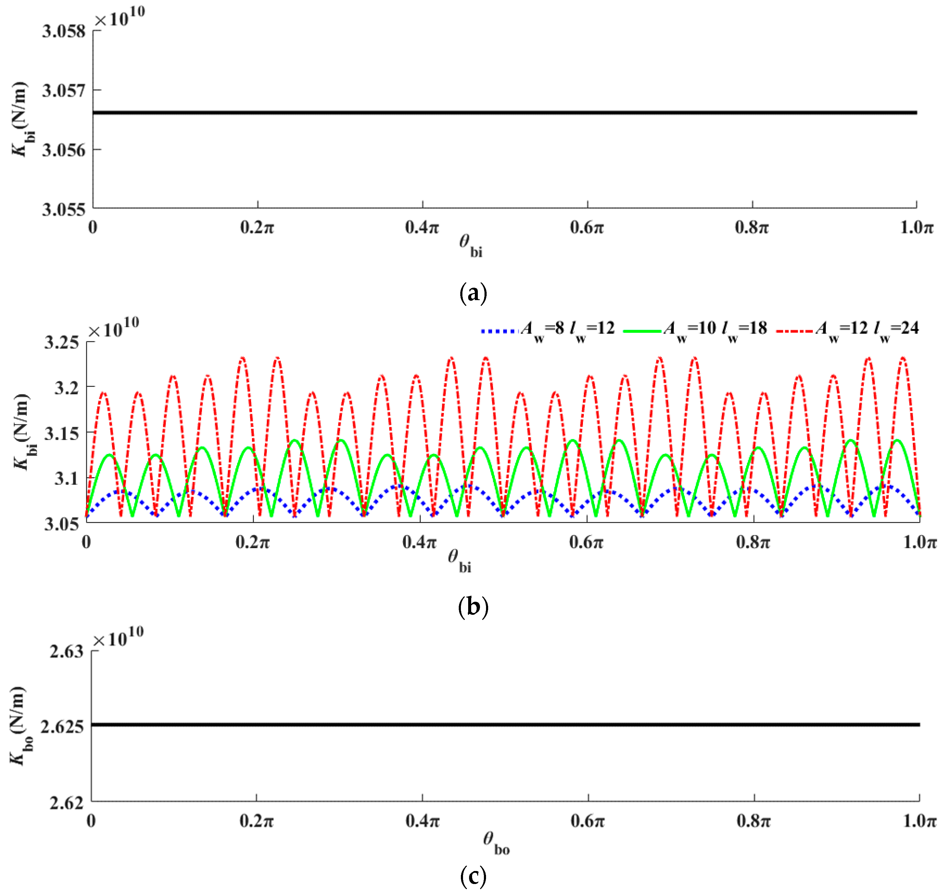
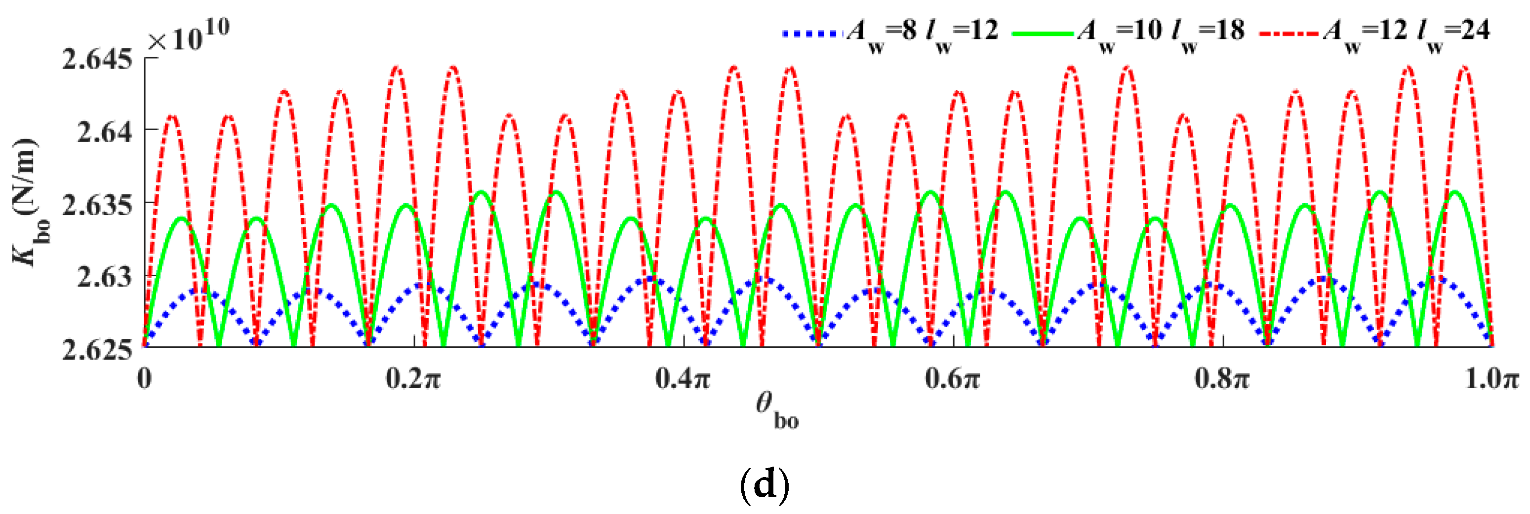
- For the SWMS, the contact stiffness of the bearing changed periodically with the rotation angle, and its period was related to the order of waviness. The higher order could obtain a shorter period. The amplitude of contact stiffness was positively correlated with that of waviness.
- (3)
- Compared with the SWMS, the contact stiffness between the roller and raceway in the SWM was constant.
Author Contributions
Funding
Data Availability Statement
Conflicts of Interest
References
- Cao, H.; Li, Y.; Chen, X. A new dynamic model of ball-bearing rotor systems based on rigid body element. J. Manuf. Sci. Eng. 2016, 138, 071007. [Google Scholar] [CrossRef]
- Bai, C.; Xu, Q. Dynamic model of ball bearings with internal clearance and waviness. J. Sound Vib. 2006, 294, 23–48. [Google Scholar] [CrossRef]
- Choudhury, T.; Kurvinen, E.; Viitala, R.; Sopanen, J. Development and verification of frequency domain solution methods for rotor-bearing system responses caused by rolling element bearing waviness. Mech. Syst. Signal Process. 2022, 163, 108117. [Google Scholar] [CrossRef]
- Liu, Y.; Chen, Z.; Li, W.; Kang, K. Dynamic analysis of traction motor in a locomotive considering surface waviness on races of a motor bearing. Railw. Eng. Sci. 2021, 29, 379–393. [Google Scholar] [CrossRef]
- Liu, J.; Pang, R.; Xu, Y.; Ding, S.; He, Q. Vibration analysis of a single row angular contact ball bearing with the coupling errors including the surface roundness and waviness. Sci. China Technol. Sci. 2020, 63, 943–952. [Google Scholar] [CrossRef]
- Xi, S.; Cao, H.; Chen, X.; Niu, L. A dynamic modeling approach for spindle bearing system supported by both angular contact ball bearing and floating displacement bearing. J. Manuf. Sci. Eng. 2018, 140, 021014. [Google Scholar] [CrossRef]
- Xi, S.; Cao, H.; Chen, X. Dynamic modeling of spindle bearing system and vibration response investigation. Mech. Syst. Signal Process. 2019, 114, 486–511. [Google Scholar] [CrossRef]
- Shi, Z.; Liu, J.; Xiao, G. Dynamics of a planetary needle roller bearing considering the waviness. J. Multi-Body Dyn. 2022, 236, 308–321. [Google Scholar] [CrossRef]
- Yang, J.; Zhu, R.; Yue, Y.; Dai, G.; Yin, X. Nonlinear analysis of herringbone gear rotor system based on the surface waviness excitation of journal bearing. J. Braz. Soc. Mech. Sci. Eng. 2022, 44, 54. [Google Scholar] [CrossRef]
- Dai, P.; Wang, J.; Yan, S. Vibration characteristics of the gear shaft-bearing system with compound defects under variable operating conditions. J. Multi-Body Dyn. 2022, 236, 113–129. [Google Scholar] [CrossRef]
- Dikmen, E.; Hoogt, P. A flexible rotor on flexible supports: Modeling and experiments. In ASME 2009 International Mechanical Engineering Congress and Exposition; American Society of Mechanical Engineers: New York, NY, USA, 2010; pp. 51–56. [Google Scholar]
- Neriya, S.; Bhat, R.; Sankar, T. The coupled torsional-flexural vibration of a geared shaft system using finite element method. Shock Vib. Bull. 1985, 55, 13–25. [Google Scholar]
- Liu, J.; Tang, C.; Pan, G. Dynamic modeling and simulation of a flexible-rotor ball bearing system. J. Vib. Control 2022, 28, 3495–3509. [Google Scholar] [CrossRef]
- Yang, X.; Zhang, C.; Yu, W.; Huang, W.; Xu, Z.; Nie, C. A Refined Dynamic Model for the Planetary Gear Set Considering the Time-Varying Nonlinear Support Stiffness of Ball Bearing. Machines 2023, 11, 206. [Google Scholar] [CrossRef]
- Peng, B.; Zhang, A.; Cao, M.; Ye, J.; Wei, J. Analytical Investigation on Load Sharing Performance of Planetary Gear Transmission under Loop Maneuver. Machines 2022, 10, 1068. [Google Scholar] [CrossRef]
- Li, X.; Liu, J.; Liu, J.; Xu, Y.; Pan, G.; Shi, Z. Dynamic modeling of a spline-shaft system including time-varying fretting friction. Int. J. Mech. Sci. 2025, 294, 110192. [Google Scholar] [CrossRef]
- Li, X.; Xu, Y.; Liu, J.; Liu, J.; Pan, G.; Shi, Z. Dynamic modelling of a floating spline-coupling shaft system with parallel misalignment and tooth backlash. Mech. Syst. Signal Process. 2025, 226, 112363. [Google Scholar] [CrossRef]
- Šafář, M.; Dütsch, L.; Harničárová, M.; Valíček, J.; Kušnerová, M.; Tozan, H.; Kopal, I.; Falta, K.; Borzan, C.; Palková, Z. Comprehensive Prediction Model for Analysis of Rolling Bearing Ring Waviness. J. Manuf. Mater. Process. 2025, 9, 220. [Google Scholar] [CrossRef]
- Ebrahimi, E.; Li, S. Tribo-dynamic effects of machining caused surface waviness on a line contact. Physics of Fluids 2024, 36, 113131. [Google Scholar] [CrossRef]
- Venner, C.H.; Berger, G.; Lugt, P.M. Waviness deformation in starved EHL circular contacts. J. Tribol. 2004, 126, 248–257. [Google Scholar] [CrossRef]
- Jurko, J.; Panda, A.; Valíček, J.; Harničárová, M.; Pandová, I. Study on cone roller bearing surface roughness improvement and the effect of surface roughness on tapered roller bearing service life. Int. J. Adv. Manuf. Technol. 2016, 82, 1099–1106. [Google Scholar] [CrossRef]
- Brewe, D.; Hamrock, B. Simplified solution for elliptical-contact deformation between two elastic solids. J. Lubr. Technol. 1977, 101, 231–239. [Google Scholar] [CrossRef]
- Liu, J.; Li, X.; Pang, R. Dynamic modeling and vibration analysis of a flexible gear transmission system. Mech. Syst. Signal Process. 2023, 197, 110367. [Google Scholar] [CrossRef]
- Li, X.; Xu, Y.; Liu, J.; Wu, W. Vibration Analysis of the Double Row Planetary Gear System for an Electromechanical Energy Conversion System. Lubricants 2024, 12, 211. [Google Scholar] [CrossRef]
- Babu, C.; Tandon, N.; Pandey, R. Nonlinear vibration analysis of an elastic rotor supported on angular contact ball bearings considering six degrees of freedom and waviness on balls and races. J. Vib. Acoust. 2014, 136, 044503. [Google Scholar] [CrossRef]
- Jiang, H.; Liu, F. Mesh stiffness modelling and dynamic simulation of helical gears with tooth crack propagation. Meccanica 2020, 55, 1215–1236. [Google Scholar] [CrossRef]
- Wang, H.; Han, Q.; Zhou, D. Output torque modeling of control moment gyros considering rolling element bearing induced disturbances. Mech. Syst. Signal Process. 2019, 115, 188–212. [Google Scholar] [CrossRef]
- Xu, Y.; Liu, J.; Li, X.; Tang, C. An investigation of vibrations of a flexible rotor system with the unbalanced force and time-varying bearing force. Chin. J. Mech. Eng. 2025, 38, 25. [Google Scholar] [CrossRef]
- Xu, Y.; Li, X.; Liu, J.; Liu, J.; Pan, G. A multi-interaction electromechanical coupling dynamic model and lateral-torsional vibration mechanism of the propulsion shaft system. Mech. Syst. Signal Process. 2025, 235, 112920. [Google Scholar] [CrossRef]


| Parameters | #1 | #2 | #3 | #4 |
|---|---|---|---|---|
| Material | 40 Cr | 40 Cr | 40 Cr | 40 Cr |
| Young’s modulus/E | 209 Gpa | 209 Gpa | 209 Gpa | 209 Gpa |
| Poisson’s ratio/v | 0.30 | 0.30 | 0.30 | 0.30 |
| Width/B | 40 mm | 40 mm | 40 mm | 40 mm |
| Modulus | 4.5 mm | 4.5 mm | 4 mm | 4 mm |
| Number of teeth | 39 | 117 | 44 | 132 |
| Pressure angle | 20° | 20° | 20° | 20° |
| Spiral angle | 13.5° | 13.5° | 13.5° | 13.5° |
| Rotation direction | right | left | Right | left |
| Height coefficient | 1 | |||
| Clearance coefficient | 0.25 | |||
| Parameters | Value |
|---|---|
| Inner diameter/mm | 20 |
| Outer diameter/mm | 52 |
| Width/mm | 23 |
| Roller diameter/mm | 10.53 |
| Number of rollers | 6 |
| Radial internal clearance/μm | 10 |
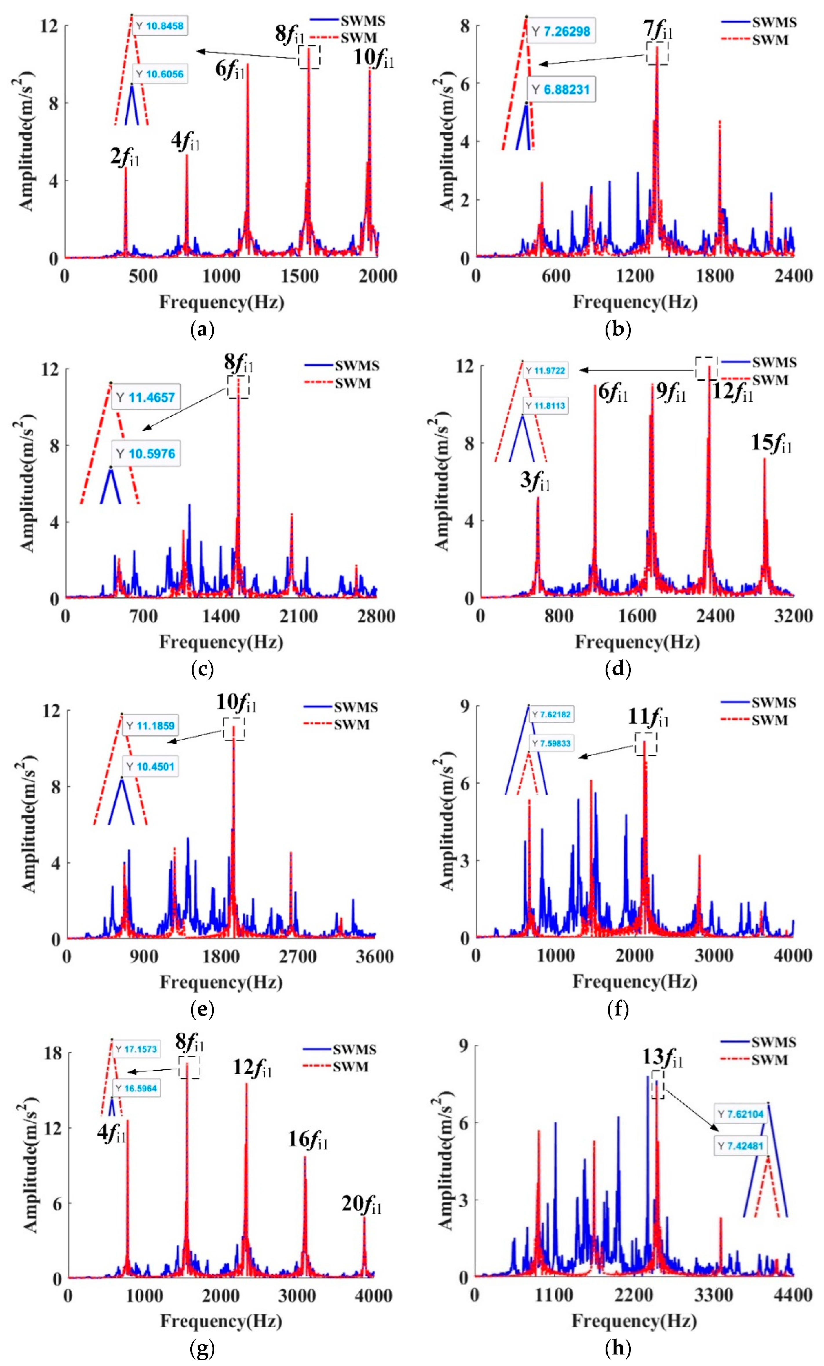
| lw | Peak Frequency (Hz) | Characteristic Frequency | Amplitude (m/s2) | |||
|---|---|---|---|---|---|---|
| SWM | SWMS | SWM | SWMS | Difference | ||
| 12 | 1551.0 | 1551.0 | 8 fi1 | 10.84 | 10.60 | 2.26% |
| 14 | 1357.1 | 1357.1 | 7 fi1 | 7.26 | 6.88 | 5.52% |
| 16 | 1551.0 | 1551.0 | 8 fi1 | 11.46 | 10.59 | 8.22% |
| 18 | 2326.5 | 2326.5 | 12 fi1 | 11.97 | 11.81 | 1.35% |
| 20 | 1938.8 | 1938.8 | 10 fi1 | 11.18 | 10.45 | 6.99% |
| 22 | 2132.6 | 2132.6 | 11 fi1 | 7.59 | 7.62 | 0.39% |
| 24 | 1551.0 | 1551.0 | 8 fi1 | 17.15 | 16.59 | 3.38% |
| 26 | 2520.4 | 2520.4 | 13 fi1 | 7.42 | 7.62 | 2.62% |
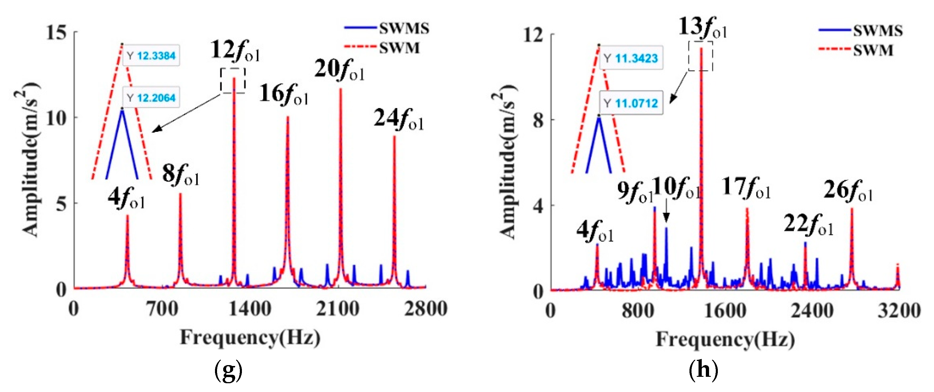
| lw | Peak Frequency (Hz) | Characteristic Frequency | Amplitude (m/s2) | |||
|---|---|---|---|---|---|---|
| SWM | SWMS | SWM | SWMS | Difference | ||
| 12 | 1273.5 | 1273.5 | 12 fo1 | 3.21 | 3.22 | 0.31% |
| 14 | 1485.7 | 1485.7 | 14 fo1 | 4.62 | 4.55 | 4.51% |
| 16 | 849 | 849 | 8 fo1 | 5.21 | 5.20 | 0.19% |
| 18 | 1273.5 | 1273.5 | 12 fo1 | 8.36 | 8.31 | 0.60% |
| 20 | 1061.2 | 1061.2 | 10 fo1 | 7.84 | 7.77 | 0.90% |
| 22 | 1167.4 | 1167.4 | 11 fo1 | 9.57 | 9.64 | 0.73% |
| 24 | 1273.5 | 1273.5 | 12 fo1 | 12.33 | 12.20 | 1.06% |
| 26 | 2520.4 | 2520.4 | 13 fi1 | 7.42 | 7.62 | 2.62% |
Disclaimer/Publisher’s Note: The statements, opinions and data contained in all publications are solely those of the individual author(s) and contributor(s) and not of MDPI and/or the editor(s). MDPI and/or the editor(s) disclaim responsibility for any injury to people or property resulting from any ideas, methods, instructions or products referred to in the content. |
© 2025 by the authors. Licensee MDPI, Basel, Switzerland. This article is an open access article distributed under the terms and conditions of the Creative Commons Attribution (CC BY) license (https://creativecommons.org/licenses/by/4.0/).
Share and Cite
Li, S.; Xu, Y.; Pang, R.; Liu, J. An Influence Analysis of the Bearing Waviness on the Vibrations of a Flexible Gear. Machines 2025, 13, 661. https://doi.org/10.3390/machines13080661
Li S, Xu Y, Pang R, Liu J. An Influence Analysis of the Bearing Waviness on the Vibrations of a Flexible Gear. Machines. 2025; 13(8):661. https://doi.org/10.3390/machines13080661
Chicago/Turabian StyleLi, Shenlong, Yajun Xu, Ruikun Pang, and Jing Liu. 2025. "An Influence Analysis of the Bearing Waviness on the Vibrations of a Flexible Gear" Machines 13, no. 8: 661. https://doi.org/10.3390/machines13080661
APA StyleLi, S., Xu, Y., Pang, R., & Liu, J. (2025). An Influence Analysis of the Bearing Waviness on the Vibrations of a Flexible Gear. Machines, 13(8), 661. https://doi.org/10.3390/machines13080661