Abstract
To improve the mobility of mobile robots in complex terrain environments, a novel 2-UPS&PRPU parallel mechanism is proposed, for which the parallel mechanism branched-chain decomposition and synthesis method is adopted. Based on the structural characteristics of the Hooke joint kinematic substructure, an inverse solution calculation for the mechanism is carried out, and the parameters of the simulation model are formulated to determine the workspace of the parallel mechanism. The linear velocity dexterity and minimum output carrying capacity of the parallel mechanism are analyzed, allowing the optimal parameters of the mechanism to be selected through dimension optimization, thus greatly improving the mechanism’s linear velocity dexterity and carrying capacity. The results show that the proposed parallel mechanism can satisfy the mobility requirements of mobile robots.
1. Introduction
The parallel mechanism offers advantages such as a large carrying capacity, high precision, and ease of control [1,2]. Wheel-legged robots with parallel mechanisms as legs have become a research hotspot in the field of mobile robots. This type of robot has advantages of adaptability to multiple terrains, such as flat and rugged terrains, good stability, and strong load-bearing capacity. It has broad application prospects in complex and variable unknown underground spaces, earth’s surface disaster rescue, planetary exploration, and other fields [3].
The configuration and layout of parallel leg mechanisms are the core foundation of the design of wheeled-legged robots, directly determining the robot’s motion performance, load-bearing capacity, and terrain adaptability in complex environments [4]. Feller [5] proposed a serial-parallel three-legged robot and solved its positive and inverse kinematics problems by means of the spherical trigonometry and spatial vector geometry methods. Li et al. [6] studied a mobile heavy-duty pouring robot based on the 4-UPU parallel mechanism to analyze its kinematics and model the pouring process. Jia et al. [7], Marínez et al. [8], and Niu et al. [9] focused on parallel/hybrid mechanisms: Jia et al. used a dual Stewart platform to optimize dynamics and stability, Martínez et al. used a 3-CUP geometry vector method to solve forward kinematics, and Niu et al.used a 3-DOF series-parallel hybrid mechanism to fully analyze the position, velocity, and stiffness. All three verified the advantages of parallel mechanisms in the design of robots with high stiffness and stability.
Li et al. [10] synthesized a family of modular 3-DOF parallel leg mechanisms, which consisted of a 3-DOF drive system and a 2-DOF walking mechanism. A larger and more regular workspace endowed the walking robot with strong obstacle-surmounting capacity. Zhang et al. [11] proposed a 3-DOF leg mechanism for a hexapod firefighting robot, which is composed of a 2RUS + RU parallel mechanism as a driving mechanism and a spatial parallelogram mechanism as walking mechanism, and the two are connected by a spherical pair. A dynamics model was developed, and the leg mechanism was improved to reduce the torque requirement of the drive joints. Efrain et al. [12] presented a design, kinematic analysis, and dimensional optimization methodology for a linear triangular parallel robot aimed at improving performance and efficiency in additive manufacturing (3D printing). Sang et al. [13] presented a human-carried quadruped walking robot based on the 2-UPS + UP parallel leg mechanism and investigated its kinematic analysis, gait planning, and control strategy. Wu et al. [14] presented a 5-DOF hybrid leg mechanism and its application to a quadruped Earth exploration vehicle, BJTUBOT.
Parallel leg mechanisms with reconfigurable or deformable features can better adapt to complex environments and various tasks through mode switching. Xu et al. [15] proposed a metamorphic parallel leg mechanism with a reconfigurable moving platform, which evolves from a full configuration state to a specific configuration state by increasing constraints or decreasing DOFs. Zhang et al. [16] designed a 4-DOF parallel bipedal robot mechanism that adopts an improved virtual chain method for type synthesis, optimizes the hip joint design, and designs the lower limb mechanism based on the humanoid principle. Zhao et al. [17] proposed a 3-DOF serial-parallel hybrid leg design. It optimizes the leg structure of a quadruped robot by combining the advantages of the large workspace of the serial mechanism and the high stiffness and load-carrying capacity of the parallel mechanism. These studies have mainly focused on basic theoretical issues, such as structure design, kinematic modeling, and dynamic analyses of parallel or hybrid robots. However, there are issues with complex mechanisms and redundant drivers, resulting in heavy system weight, high costs, and complex controls.
An et al. [18] studied the dynamic behavior of an integrated crawler mobile parallel robot under obstacle-crossing conditions, such as climbing steps, spanning gaps, and climbing slopes, analyzing its kinematic stability, contact force variations, and slippage rate fluctuations. Li et al. [19] designed a multi-modal mobile robot based on a quadrupedal parallel mechanism, with branching variations. The robot has three locomotion modes: leg mode, wheel mode, and tracked mode, and seven gaits: tracked rolling, stair and slope climbing, gap crossing, trot walking, fast moving, and direction-switching gait. Zhao et al. [20] proposed a self-reconfigurable dobby robot mechanism design method based on deployable kinematic chains (DKCs). Niu et al. [21] proposed a wheel-legged rescue robot with a (2-UPS + U)&R series-parallel structure. The structure modeling and kinematic characteristics of the robot were presented. The leg mechanism can meet the requirement of walking in the unstructured environment. Ping et al. [22] designed a multi-mode mobile parallel mechanism with a deployable platform for patrolling and monitoring industrial substation areas. Ushimi [23] developed a four-wheeled reconfigurable mobile robot for sloping terrain that adjusts its body attitude and center of gravity by means of a parallel linkage mechanism and four active legs to avoid wheel slipping and overturning. Zhao et al. [24] proposed an inverted modeling method to support motion planning for footed robots. Pan et al. [25] investigated the computational complexity of the kinematic model of a hexapod robot with two 1UP-2UPS parallel mechanism topologies. Although these studies have provided useful solutions for obstacle-crossing modes, mechanism reconstruction, and environmental adaptability, there are also general problems, such as complex mode-switching mechanisms, low reliability, and difficulty of maintenance.
Wheel-legged robots have made significant progress in lightweighting, biomimetic gait, and stability assessment. Hao et al. [26] designed a single-leg walking mechanism for a quadruped robot, which is composed of a crank rocker mechanism and scaling mechanism in series. The advantages of the single-leg walking mechanism are fewer driving elements, more simple design, and high gait stability. Chamas et al. [27] proposed a stabilization scheme for unmanned aerial vehicle platforms based on a 3-SRR parallel mechanism. They introduced an artificial neural network control strategy, significantly improving the stability and accuracy of the system under complex disturbances. Liu et al. [28] and Tazaki et al. [29] both pursued lightweight, multi-modal locomotion: the former presented a two-segment series-parallel worm robot that combines straight-line, lateral, and peristaltic gaits, while the latter embedded all six actuators in the torso to minimize the leg inertia of a 6-DOF parallel-link bipedal leg. Xu et al. [30] proposed a gait analysis method for a radially symmetric hexapod robot based on a parallel mechanism. Liu et al. [31] presented a hexapod walking machine tool for kinematic calibration, which is composed of a six-legged robot integrated with a parallel manipulator on the body. Through the inverse kinematics bias-based objective function optimization method, the hexapod robot and its parallel manipulator showed improved kinematic accuracy. Fu et al. [32] introduced a dynamic stability assessment method called moment ratio stability margin (MRSM). Pan et al. [33] analyzed the fault tolerance and walking capability of a parallel hexapod walking robot, defined the leg fault tolerance criterion, and demonstrated the robot’s capability to walk in the case of fault tolerance failures of a single leg or both legs.
Despite extensive theoretical research on wheel-legged robots based on parallel mechanisms, there are still some technical challenges. Existing robots often struggle to balance their adaptability to complex terrains with structure compactness, especially in terms of multi-mode motion switching.
Unlike existing research, this study proposes a novel 2-UPS&PRPU parallel mechanism used for mechanical legs and constructs a six-wheel and four-leg robot, abbreviated as 6W4L robot. The auxiliary devices added to the mechanical legs enable it to freely switch between wheels and legs, greatly improving its ability to navigate in changing terrain environments.
The remainder of this article is organized as follows. In Section 2, a novel 2-UPS&PRPU parallel mechanism is proposed to improve the mobility of mobile robots in complex terrain environments. Section 3 details the kinematic analysis of the parallel mechanism. Section 4 presents the performance analysis, including a dexterity analysis, carrying capacity analysis, and dimension optimization. An application example is provided in Section 5. The conclusions are drawn in Section 6.
2. Configuration Analysis
2.1. Configuration of 2-UPS&PRPU Parallel Mechanism
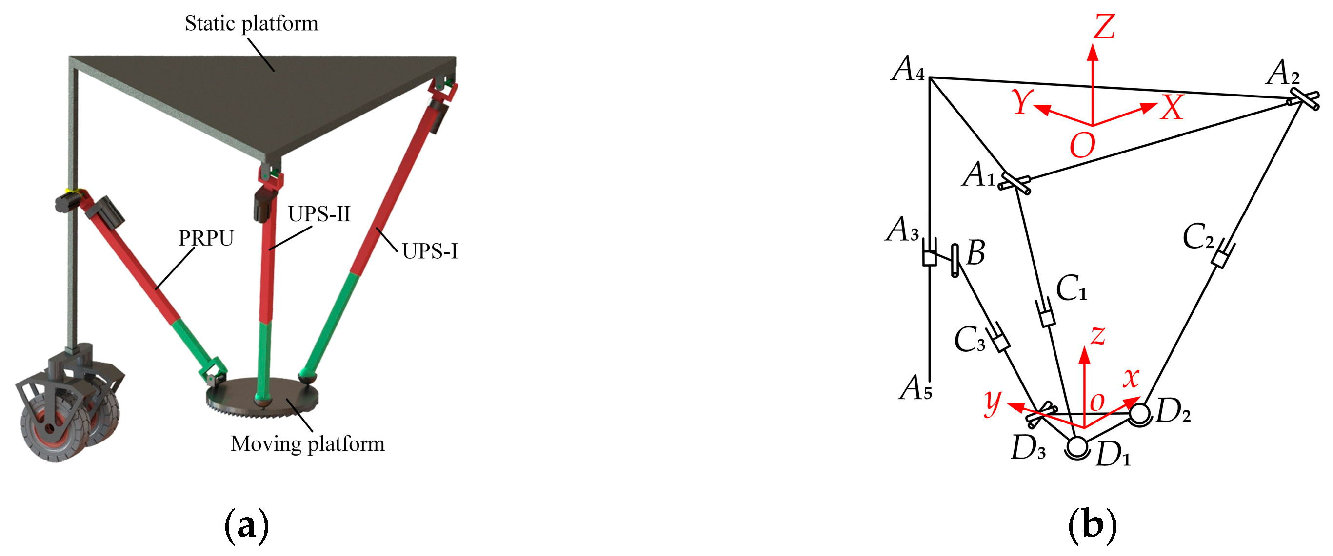
The designed 2-UPS&PRPU parallel mechanism with variable DOFs is shown in Figure 1a. The parallel mechanism consists of a static platform, a moving platform, two UPS branched chains, and one PRPU branched chain. A kinematic diagram of the 2-UPS&PRPU parallel mechanism is shown in Figure 1b.
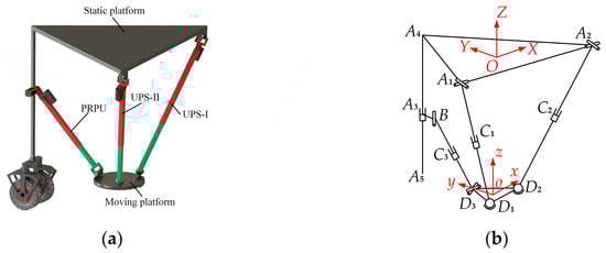
Figure 1.
Parallel mechanism diagram: (a) 2-UPS&PRPU parallel mechanism model and (b) kinematic diagram of 2-UPS&PRPU parallel mechanism.
The static platform, A1A2A4, is an equilateral triangular structure, and the rod, A4A5, is fixed to vertex A4 of the triangle. The moving platform, D1D2D3, is a circular structure, but the kinematic pairs of the three branched chains connected to the moving platform also form an equilateral triangle.
Hooke joints A1 and A2 of the two UPS branched chains are connected to the static platform, and the spherical pairs D1 and D2 are connected to the moving platform. In the PRPU branched chain, the first prismatic pair, A3, moves along A4A5, the Hooke joint D3 is connected to the moving platform, and revolute pair B is fixed to A3.
The coordinate system (O-XYZ) of the static platform is fixed. The coordinate origin, O, is fixed at the geometric center of the static platform with an equilateral triangle, the X-axis is parallel to A1A2, pointing from A1 to A2, the Y-axis passes through vertex A4 of the triangle, and the Z-axis is upwardly perpendicular to the static platform.
The coordinate system (o-xyz) of the moving platform is also fixed. The coordinate origin, o, is fixed at the geometric center of the moving platform, the x-axis is parallel to D1D2, pointing from D1 to D2, the y-axis passes through vertex D3, and the z-axis is upwardly perpendicular to the moving platform.
2.2. DOFs Calculation of 2-UPS&PRPU Parallel Mechanism
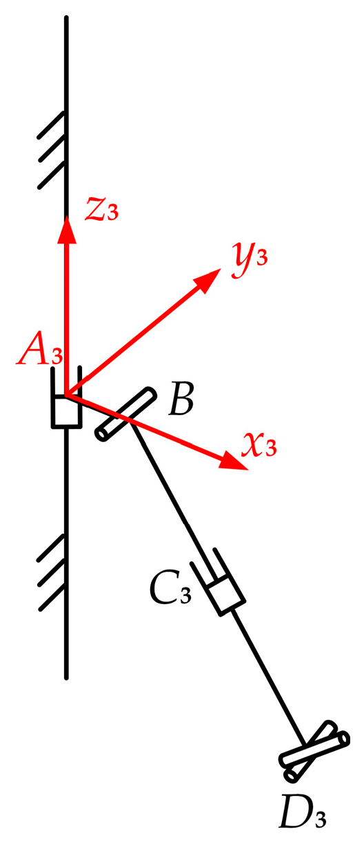
Screw theory is used to determine the DOFs of the 2-UPS&PRPU parallel mechanism. For the PRPU branched chain, the branched-chain coordinate system A3-x3y3z3 is established, and the origin of the coordinate system is located at the A3, x3 prismatic pair axis, which is perpendicular and points in the direction of the branched chain. The z3 axis is upward along the guide of prismatic pair A3, and the direction of the y3 axis is determined using the right-hand rule, as shown in Figure 2.
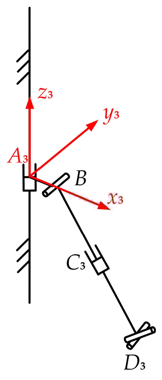
Figure 2.
Coordinate system of the PRPU branched chain.
The PRPU branched chain’s helical system of motion in this coordinate system can be expressed as:
where f12 represents the torque of the spherical pair B in the z3 axis direction in Figure 3, d13 and f13 represent the torques of the prismatic pair C3 in the x3 and z3 directions, d14 and f14 represent the torques in the x3 and z3 directions of the spherical pair parallel to y13 in Hooke joint D3, a15 and c15 represent the direction cosine of the spherical pair in the x3 and z3 directions, which is not parallel to y3 in Hooke joint D3, and e15 represents its torque in the y3 direction.
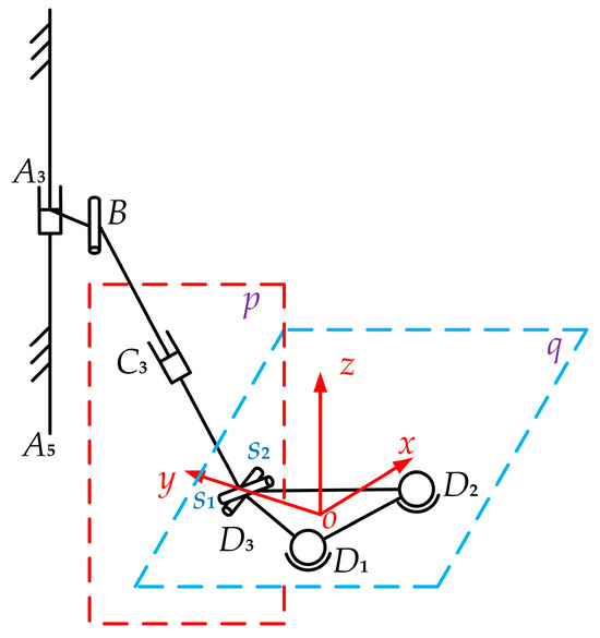
Figure 3.
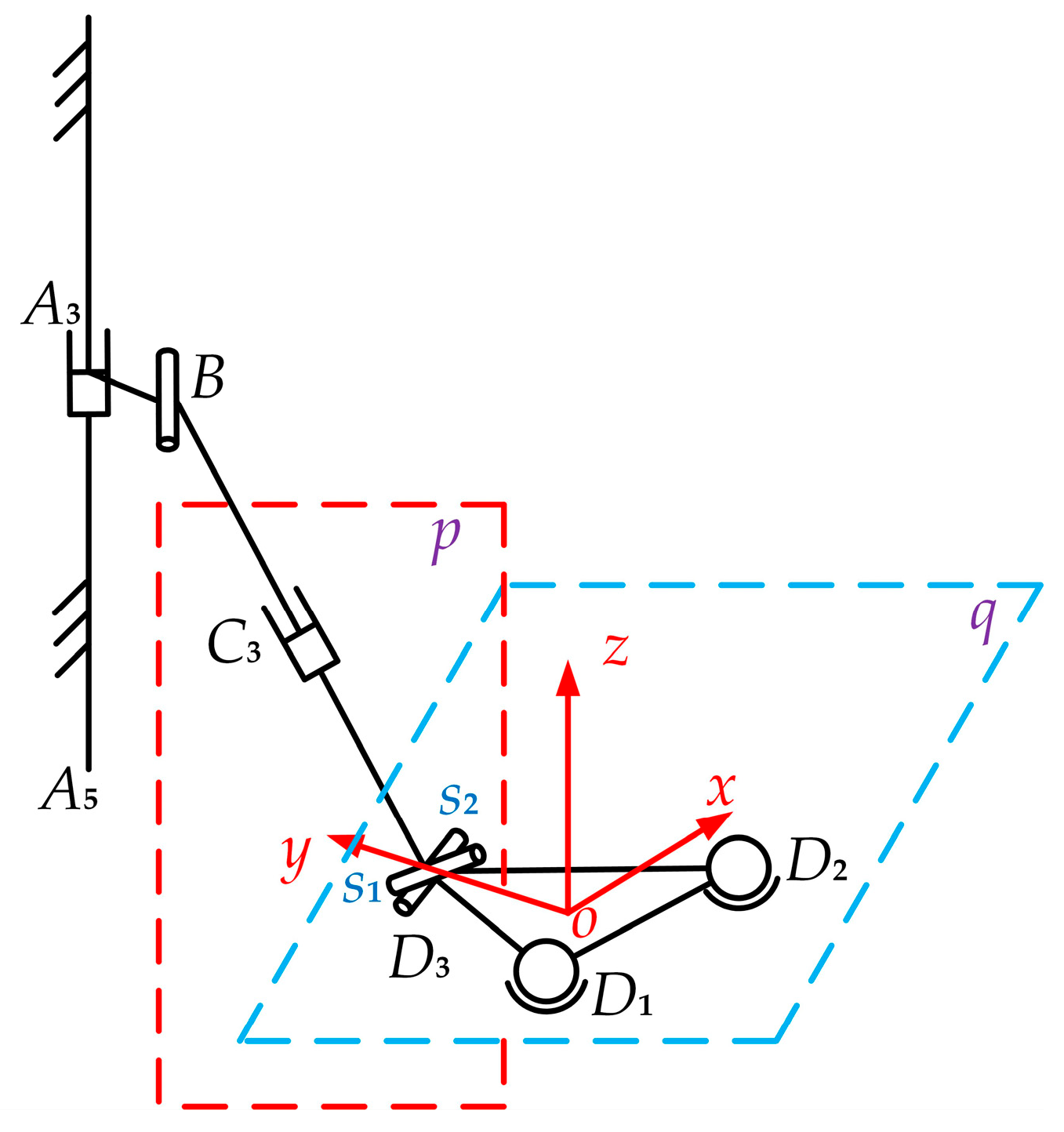
The PRPU branched chain.
According to the reciprocal product relationship of the twist between the motion and constraint, the constraint twist of Equation (1) can be determined as follows:
The PRPU branched chain is subject to two constraint twists in this state, which constrain the movement of the Hooke joint U end of the PRPU branched chain along the X-axis direction and the rotation axis perpendicular to the rotation axis of the Hooke joint U end. Similarly, we can establish the coordinate system of the 2-UPS branched chain to analyze the motion helix, determining its motion helix as follows:
The expression of the parameters in Equation (3) is similar to that of the parameters in Equation (1).
Analyzing the helix in Equation (3) shows that its rank is 6, and there is no constraint helix, meaning that the branched-chain UPS has a spatial 6-DOF kinematic performance. In summary, the analysis of the three branched chains connecting the moving platform shows that the 2-UPS&PRPU parallel mechanism has four DOFs in this mode in one case. However, it cannot achieve movement along the X-axis and, at the same time, it cannot rotate around the axis perpendicular to the end face of the Hooke joint U end at point D3.
The DOFs of the parallel mechanism can be calculated based on the modified Grübler–Kutzbach equation:
where the order of the parallel mechanism is d = 6, the number of all the rods in the mechanism (including the frame) is n = 9, the number of kinematic pairs in the mechanism is g = 10, all the kinematic pairs form 17 DOFs, and there are no redundant constraints in the mechanism (v = 0). Since the revolute pair R in the PRPU branched chain and one of the Hooke joints in the rotating axes of the mechanism are parallel during the motion process, the local DOF is δ = 1.
Thus, our analysis and validation show that the 2-UPS&PRPU parallel mechanism has a total of 4 DOFs.
3. Kinematic Analysis
3.1. Inverse Solution Calculation
As shown in Figure 1b, since the 2-UPS&PRPU parallel mechanism has four DOFs, we need to provide at least four drives for the mechanism to achieve the motion function of the mechanism. Therefore, we set the variations of four prismatic pairs as the mechanism drives, including the length li (i = 1, 2, 3) of the rod AiDi (i = 1, 2) and BD3, and the length l4, which represents the displacement A3A4 of the driving pair A3 in the rod A4A5.
The inverse solution problem of the 2-UPS&PRPU parallel mechanism is to solve the length li (i = 1, 2, 3) of the equivalent driving rod for given position parameters and orientation parameters (x, y, z and α, β, γ) of the moving platform.
The rotation angle of the revolute pair B around the X-axis is denoted by θ. The side length of the static platform is 2R, and the side length of the moving platform is 2r. The prismatic pair A3 and the revolute pair B in the branched-chain PRPU are solidly connected, and the distance k between the two is fixed. The parameters of the static platform can be expressed in the static coordinate system as:
The coordinates of the moving platform in the moving coordinate system are expressed as:
Based on the fixed coordinates, the coordinate transformation of the moving coordinates is based on the X-Y-Z-type mode with the transformation matrix
where c represents cos, and s represents sin.
The transformation of the coordinates of the moving platform in the fixed system can be expressed as:
where P represents the relative position of the coordinate origin of the moving platform relative to the fixed coordinate system of the static platform.
To facilitate calculations, the transformation matrix T is abbreviated as:
The parameters in Equation (9) correspond to the parameters in Equation (7). Substituting these parameters into Equation (8) yields:
According to the closed-loop vector method, the length of each rod can be determined as the modulus of its endpoint vector. Due to structural constraints, the transverse coordinate of OD3 should be 0. After the above analysis, the lengths l1 and l2 can be obtained by calculating the position of the end piece, but the θ angles of l3 and l4, as well as revolute pair B, are still undeterminable. However, only two of the three unknowns need to be determined to determine the third.
According to the structural properties of Hooke joint D3, its two rotating axes are perpendicular to each other. In Figure 3, D3 connects the PRPU branched chain and the moving platform. Since the PRPU branched chain moves up and down along vertical guide A4A5 in the static platform, its motion plane is plotted as the p-plane in Figure 3. One rotation axis, s2, in D3 moves in the p-plane, and the direction of the s1 rotation axis is related to the angle of rotation (θ) of the R pair in the PRPU branched chain. After the center of D3 is parallel to the moving platform, determining a plane q, combined with the mechanism model in Figure 1a, another rotation axis (s2) of D3 is parallel to the x-axis of the coordinate system of the moving platform. This changes with the motion of the moving platform, but the relative position remains unchanged. The rotation axes s1 and s2 are always perpendicular to each other, and do not change with the movement of the mechanism.
The initial direction of vector s2 is s2 = (1, 0, 0), and its coordinates in the fixed coordinate system will change with the motion of the moving platform:
For the PRPU branched chain, the prismatic pair A3 and the revolute pair B are always in the same horizontal position, and it is assumed that the change in revolute pair B is expressed through the angle between the connecting rod of the PRPU and the vertical rod of the fixed platform. Thus,
where θ is the angle between BD3 and A4A5.
The mutual perpendicularity of the two rotation axes of the Hooke joint can be obtained as:
At the same time:
Equation (11) shows that the rotational drive of the PRPU branched chain is only related to the angles of the end pieces around the Y- and Z-axes. In this example, we assume that the angles of the end pieces around the X- and Y-axes are independent, and the angle around the Z-axis is non-independent.
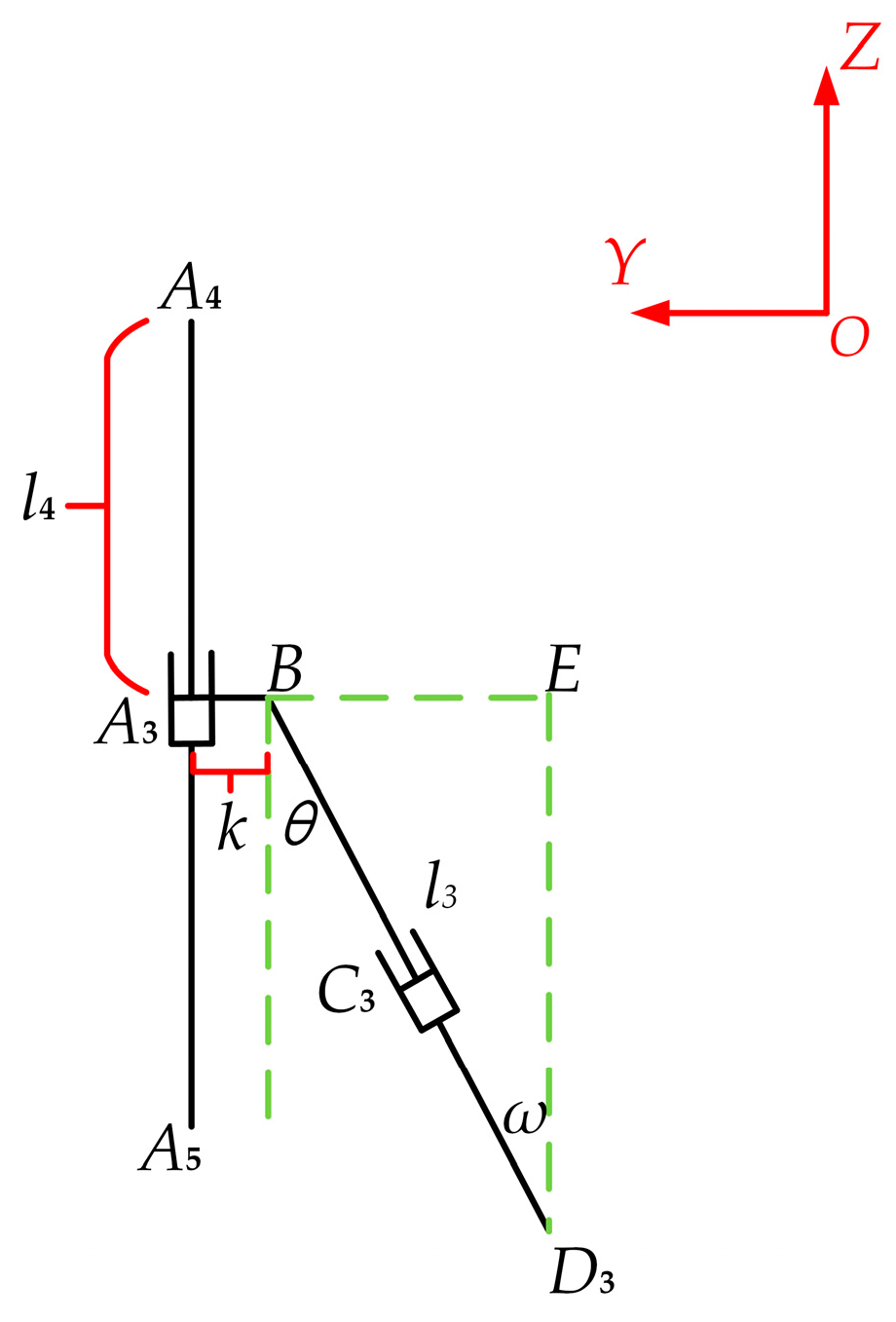
The lengths of l3 and l4 and the known coordinate parameters of point D3 can be determined with the positional display in Figure 4, as follows:
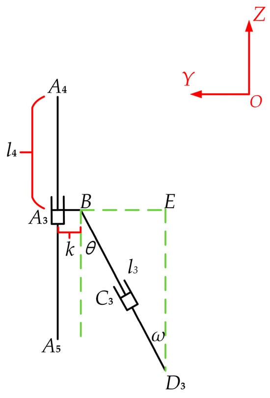
Figure 4.
Analysis diagram of the driving rod length solution.
In the mechanism end piece around the fixed coordinate system of the three rotation axes for (α β γ)—where two are independent and one non-independent—we can determine that α and β are independent; now, we can analyze the relationship between the three angles of rotation. α is the tangent value angle of the origin of the dynamic coordinate system and the difference in point D3 in the Z-axis. It is also the projected difference in the value ratio of the Y-axis. It is determined through simplification:
In summary, the inverse solution drive solution equation for the 2-UPS&PRPU parallel mechanism can be obtained as follows:
where t11 = cβcγ, t12 = sαsβcγ−cαsγ, t21 = cβsγ, t22 = sαsβsγ + cαcγ, t31 = −sβ, and t32 = sαcβ:
In addition, l4 can be determined according to Equation (15). Therefore, the mechanism has four drive inputs, three prismatic actuations, and one revolute actuation, and the four outputs are the YZ coordinates of the moving platform and rotations around XY.
3.2. Singularity Analysis
In the process of movement, the parallel mechanism may appear to be a singular configuration. However, a singular configuration will change the DOFs, such that motion coherence is reduced. Therefore, singularity analysis of parallel mechanisms is particularly important. In the following, we use the properties of the Jacobian matrix of the mechanism to analyze its singularities:
where denotes the input drive velocity of the mechanism, v represents the output velocity of the moving platform, Jq represents the input Jacobian matrix of the mechanism, and Jp represents the output Jacobian matrix:
According to Equation (17), the mechanism undergoes positional singularity when θ is equal to 0° and 90°. Below, we detail the two singular configurations that have appeared.
The Hooke joint will have different kinematic properties in different postures owing to its special characteristics. In the PRPU branched chain of the 2-UPS&PRPU parallel mechanism, one of the Hooke joints changes with the branched chain’s postures, and the moving rod, BD3, passes through the center of this Hooke joint at point D3. It perpendicularly lies in the plane formed by two rotating pivots in the Hooke joint. Since the UPS branched chain does not provide constraints on the moving platform, the variation in the DOFs of the moving platform mainly relies on the PRPU branched chain.
According to the different positions of the PRPU branched chain—i.e., the axis where BD3 is located is at a different angle to the static platform in the branched chains—the structural modes of the mechanism are divided into three cases. When the angle between BD3 and the static platform is anything other than 0° and 90°, it is the normal mode, when BD3 is parallel to the static platform, it is in mode II, and when BD3 is perpendicular to the static platform at 90°, it is in mode III. Modes II and III are the singular pattern cases when θ is equal to 0° and 90°.
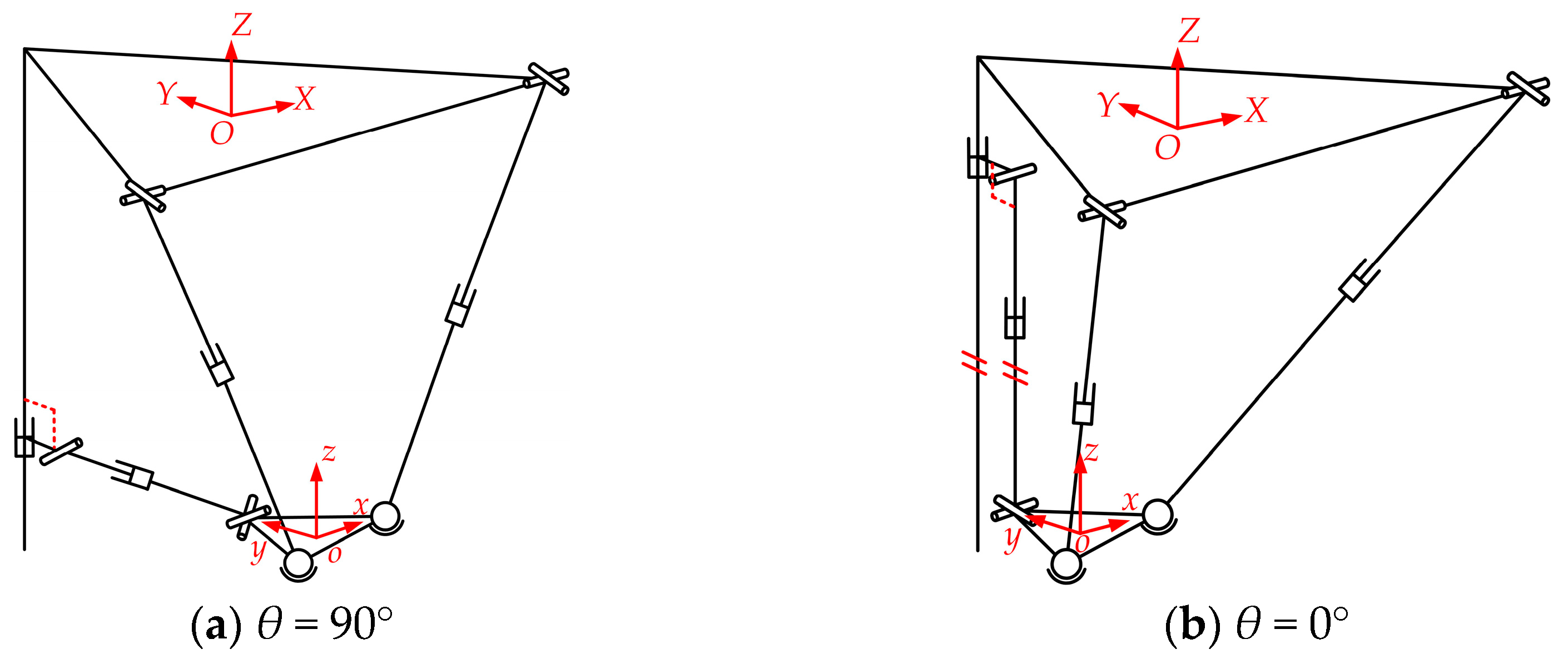
Mode I is the normal mode. Figure 5 shows two singularity position patterns of the 2-UPS&PRPU parallel mechanism during the motion process. These two singular patterns also have four DOFs, but their modes are different. Figure 5a shows the state of mode II, and Figure 5b shows the state of mode III.
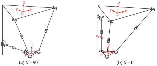
Figure 5.
The singularity positions of the 2-UPS&PRPU parallel mechanism: (a) mode II and (b) mode III.
When the mechanism is in mode II, the singularity position type, the moving rod of the PRPU branched chains is parallel to the static platform. At this time, the parallel mechanism still has four DOFs, the Hooke joint of branched chain 3 is in a vertical state, and the moving platform cannot move along the X-axis or rotate around the Y-axis because of the constraints caused by branched chain 3. When applying this mechanism to the branch legs of a mobile robot, this situation arises due to its inability to rotate around the Y-axis. In uneven lateral road conditions, the moving platform may only have partial contact with the ground while the other part is suspended, which can cause uneven force on the left and right support chains of the parallel mechanism, affecting the stability of the robot’s movement. However, this state is conducive to turning under smooth road conditions.
When the mechanism is in the singularity position of mode III, the moving rod in the PRPU branched chain is perpendicular to the static platform. At this time, the parallel mechanism still has four DOFs, the Hooke joint of branched chain 3 is in a horizontal state, and the movable platform is constrained by the branched chain 3, unable to move along the X-axis or rotate around the Z-axis. When applying this mechanism to the branch leg of a mobile robot, this situation arises due to its inability to rotate around the Z-axis. In this state, the robot cannot turn. Owing to the vertical force concentration of the PRPU branch, the service life of the rod will be reduced. Moreover, the PRPU branched chain will be too close to the A4A5 branch, and improper control can also cause collisions between the rods, increasing the requirement for control accuracy. Therefore, in practical processes, this position should be avoided as much as possible.
3.3. Workspace Analysis
Below, we carry out a workspace analysis for the case of non-singular positions. The workspace of the mechanism can directly illustrate the spatial range that can be reached by the end-effector of the mechanism. Assuming the initial parameters of the parallel mechanism (R = 200 mm, r = 50 mm, and k = 10 mm), since the contact end of the PRPU branched chain and the static platform can achieve different structures in several positions, we first analyze its specific position, i.e., when l4 = 250 mm.
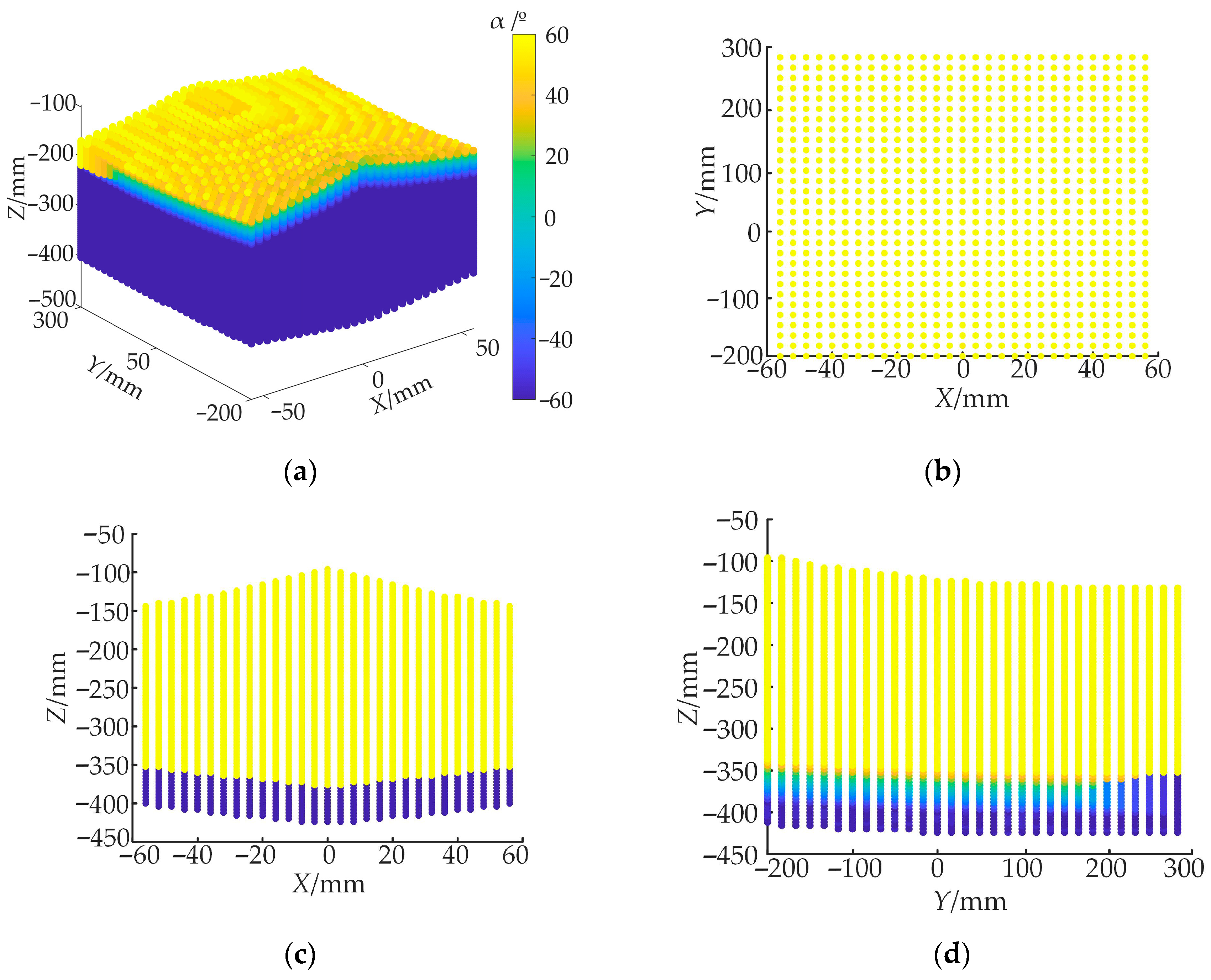
The maximum angle between the thigh and vertical direction during human and animal stepping is representative of the stepping ability of parallel mechanisms, such as moving legs; thus, the rotational angle θ of the PRPU branched chain was considered as 60°. Due to the application of parallel mechanisms in the branched legs of mobile robots, we aim to achieve forward and backward movement, whereas a set of human leg movements requires lifting, extending, and landing. To complete these movements in this design, the parallel mechanism aims to achieve rotation around the X-axis and movement in the Y-Z plane. Therefore, certain rotations were overlooked in the simulation design, and we can assume that the rotation angles of the end effector around the Y- and Z-axes are both 0. Given these mechanism parameter settings, the workspace of the mechanism can be obtained, which is shown in Figure 6.
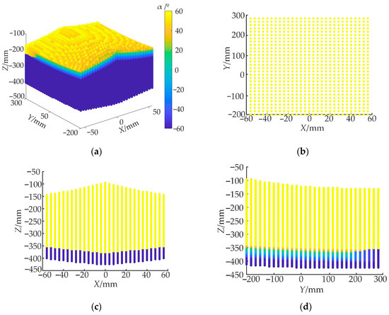
Figure 6.
Workspace of the 2-UPS&PRPU parallel mechanism: (a) three-dimensional diagram of the workspace of the parallel mechanism, (b) X-Y plane projection of the workspace at Z = −200, (c) X-Z plane projection of the workspace at Y = 0, and (d) Y-Z plane projection of the workspace at X = 0.
The workspace under specific conditions is shown in Figure 6a, demonstrating the position of the end actuator of the mechanism in the X-Y-Z axis direction and its rotation around the X-axis. Its working range meets the working requirements when installed on both sides of the 6W4L robot, and the movement along the X-axis direction can realize the robot’s forward torsion. Figure 6 shows that the parallel mechanism has a large moving space in different directions, which can meet the walking space range of the mobile robot; furthermore, the overall space change area is smooth, verifying the feasibility of the parallel mechanism.
4. Performance Evaluation of 2-UPS&PRPU Parallel Mechanism
4.1. Dexterity Analysis
Dexterity is an index that evaluates the DOF in the transfer relationship between the input and output motions of a robot. We used the condition number of the Jacobian matrix to evaluate the dexterity of the robot, which reflects the accuracy of the transfer relationship between the robot’s inputs and outputs. According to the analysis in Section 3.1, the 2-UPS&PRPU parallel mechanism has three moving drives and one rotating drive, and its outputs are two linear displacements and two rotating displacements. Considering the effect of magnitude, the mechanism’s output linear velocity and output angular velocity are analyzed separately.
If |Jp| ≠ 0 in Equation (16), then Equation (16) can be written as:
where J is the Jacobian matrix of the mechanism.
From Equation (18), the mechanism velocity transfer relation is given by the following equation:
where JV is the output linear velocity transfer matrix, which is a 2 × 4 matrix, and Jω is the output angular velocity transfer matrix, which is also a 2 × 4 matrix.
According to Equation (19), the transfer accuracy between the input and output of the mechanism depends on the matrices JV and Jω, respectively, and the condition numbers κ(JV) and κ(Jω) can be used as a measure of the mechanism’s performance in linear and angular velocity transfer:
To avoid the increasing condition number of the Jacobian matrix, its inverse is used to evaluate the dexterity index of the mechanism. Since the inverse of the condition number is related to the configuration, the inverse condition number of the output linear velocity transfer matrix is called the local condition index for the linear velocity (LCIV), and the inverse condition number of the output angular velocity transfer matrix is called the local condition index for the angular velocity (LCIω). These are expressed as follows:
According to Equation (21), the values of LCIV and LCIω range from 0 to 1. Smaller values indicate that the dexterity of the mechanism is poor, and the closer they are to 1, the better the dexterity of the mechanism.
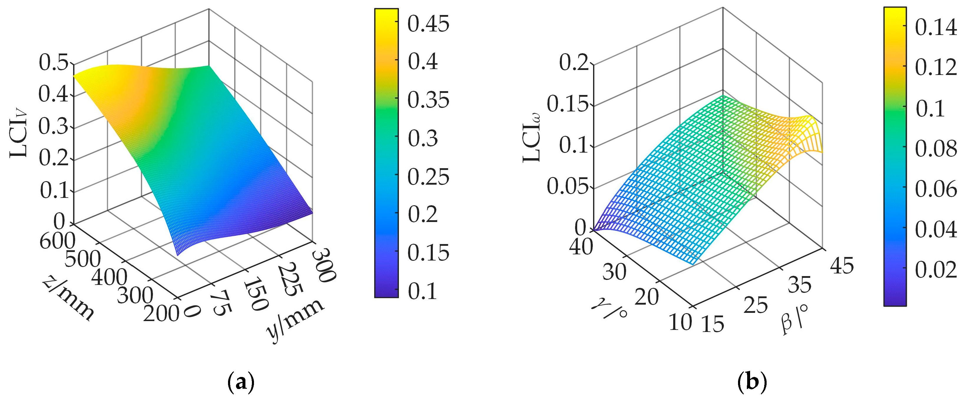
Using the structure parameters R = 200 mm, r = 50 mm, and k = 10 mm, the linear velocity dexterity and angular velocity dexterity of the mechanism are analyzed below. Firstly, the linear velocity dexterity of the mechanism is analyzed at different positions for β = 10° and γ = 10°, as shown in Figure 7a. Next, the angular velocity dexterity of the mechanism is analyzed at different rotation angles for y = 0 mm and z = 400 mm, as shown in Figure 7b.
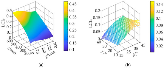
Figure 7.
Dexterity: (a) distribution of LCIV at β = 10° and γ = −10° and (b) distribution of LCIω for y = 0 mm and z = 400 mm.
4.2. Carrying Capacity Analysis
Carrying capacity is one of the most important properties of a parallel mechanism, determining whether the mechanism can support external forces acting on the moving platform. There is a direct relationship between the generalized force and the Jacobian matrix. The generalized external force F acting on the moving platform and the generalized driving force τ of the driving pair are related by the following equation:
where G is the force of the Jacobian matrix in the mechanism.
Based on the inconsistency of the force/torque magnitude, the force of the Jacobian matrix in the mechanism is disassembled according to the force/torque structure, dividing it as in the following equation:
where Gf is the force transfer part of the force of the Jacobian matrix and GM is the torque transfer part of the force of the Jacobian matrix.
Equation (22) can be rewritten as:
The load-carrying force/torque is defined as the extreme value of the mode of the external force vector F when the mode of the driving force vector τ is 1, i.e., the open square of the largest and smallest eigenvalues of the matrices and :
Here, the output load-carrying capacity/torque extremes are taken as a measure of the load-carrying capacity of the mechanism. In principle, ‖f‖max, ‖f‖min, ‖M‖max, and ‖M‖min can be used as load-carrying capacity indicators. In practice, the desired minimum output load-carrying capacity should be greater. The larger the minimum load-carrying capacity/torque, the better the load-carrying capacity of the mechanism; therefore, only the minimum output load-carrying capacity/torque is considered here.
Firstly, for β = 10° and γ = −10°, the moving platform turning angle is constant. The minimum output load-carrying capacity of the mechanism at different positions was thus analyzed, as shown in Figure 8a. Secondly, for y = 0 mm and z = 400 mm, the moving platform position is constant, and the minimum output load-carrying torque of the mechanism at different turning angles was analyzed, as shown in Figure 8b.
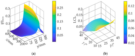
Figure 8.
Minimum output carrying capacity: (a) distribution of ‖f‖min at β = 10° and γ = −10° and (b) distribution of ‖M‖min for y = 0 mm and z = 400 mm.
Figure 8a shows that the minimum output carrying capacity of the mechanism first increases and then decreases with an increasing y value, reaching its maximum value near y = 225 mm. In Figure 8b, the minimum output carrying torque of the mechanism increases with an increasing β value and decreases with an increasing γ value.
4.3. Dimension Optimization
In the 2-UPS&PRPU parallel mechanism, the range of geometrical size parameters can theoretically tend to infinity. Therefore, the geometrical dimensions are determined in a fixed region according to the parameter dimensionless method. The main parameters for the dimension optimization of the parallel mechanism are the static platform side length R, the moving platform side length r, and the rod length k. The following equation can be used to obtain dimensionless parameters:
where D is the normalization factor, and r1, r2, and r3 are the dimensionless R, r, and k, respectively.
Having processed the dimensionless mechanism parameters, we can see that, given the actual size of the parallel mechanism requirements, the dimensionless parameters also need to meet certain geometric conditions to limit the parameter range of change. Thus, they must meet the following inequalities:
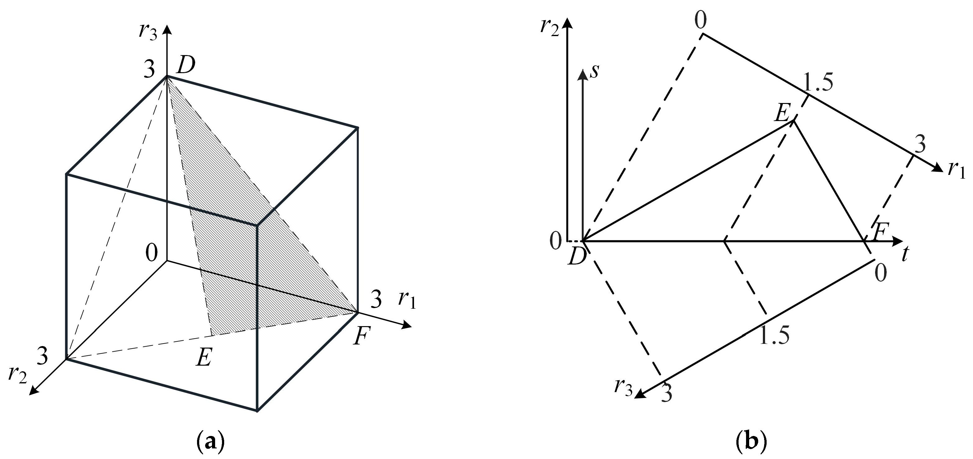
According to the optimization constraints of r1, r2, and r3, the optimized design space can be obtained in 3D space, as shown in Figure 9a. The shaded region denoted by △DEF contains all the possible cases taking the values of the dimensional variables. By choosing a reasonable 2D coordinate system in 3D space, the shaded region can be mapped to 2D space, as shown in Figure 9b.
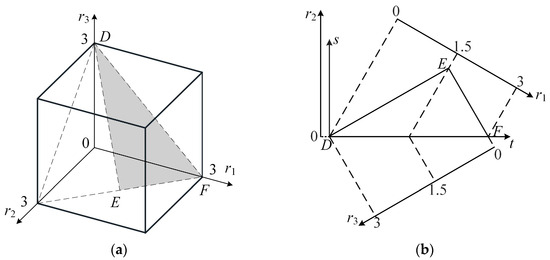
Figure 9.
Optimizing design space: (a) three-dimensional space and (b) two-dimensional space.
The relationships between r1, r2, and r3 and s, t in two dimensions are expressed by Equation (28):
The local performance indicators of the mechanisms are related to their position, and, during movement, the moving platform needs to have better accuracy and load-carrying capacity. For this reason, the global comprehensive index of velocity (GCIV) and global comprehensive index of load-carrying capacity (η‖f‖min) are defined for the workspace of the parallel mechanism, reflecting the average value of the local dexterity and load-bearing capacity of all configurations in that workspace:
Based on the definitions of GCIV and η‖f‖min, combined with the given optimized design space, a mechanism performance map can be generated, as shown in Figure 10a,b.

Figure 10.
Performance mapping: (a) GCIV and (b) η‖f‖min.
Assuming that the optimization objective needs to satisfy GCIV ≥ 0.5466 and η‖f‖min ≥ 0.0026, the optimal design space can be obtained by taking the intersection region of any maps that satisfy these performance requirements, as shown in Figure 11.
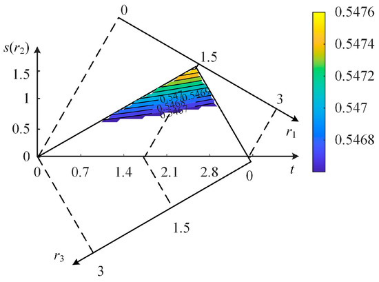
Figure 11.
Optimum design space.
Five coordinate points are selected in the target area with their corresponding dimensionless parameters, performance indicators, and structure parameters. The initial set of structure parameters for the mechanism are shown in Table 1, where GFI stands for the goodness-of-fit index, which measures the degree to which the model or design results match the expected goals. The closer the index value is to 1 or higher, the better the fitting effect.

Table 1.
Numerical results for dimensionless parameters and performance of the optimal design space.
The second set of parameters—R = 123 mm, r = 100 mm, and k = 77 mm—are selected as the optimal structure parameters of the mechanism, under which the 2-UPS&PRPU parallel mechanism has better kinematic and static performance. The mechanism is plotted using the above optimal structure parameters, with the moving platform at β = 10° and γ = −10°. Distribution diagrams of the linear velocity dexterity and minimum output carrying capacity at different positions are shown in Figure 12a,b.

Figure 12.
Optimized performance: (a) distribution of LCIV at β = 10° and γ = −10° after optimization and (b) distribution of ‖f‖min at β = 10° and γ = −10° after optimization.
5. Application Example
Four sets of 2-UPS&PRPU parallel mechanisms were installed at the four corners of a square loading platform as four supporting legs. Four sets of parallel double wheels were installed at the lower end of the vertical rod of each parallel mechanism. A rubber protective layer was laid at the lower end of the moving platform.
Due to the instability in the robot’s overall center of gravity caused by it having only four sets of wheels, two auxiliary foldable supporting legs were installed at the middle position of the front and rear ends of the loading platform, and a set of parallel dual wheels was also installed at the end of the auxiliary supporting legs. The auxiliary supporting leg structure is shown in Figure 13. The six-wheeled–four-legged hybrid mobile robot is shown in Figure 14, abbreviated as 6W4L.
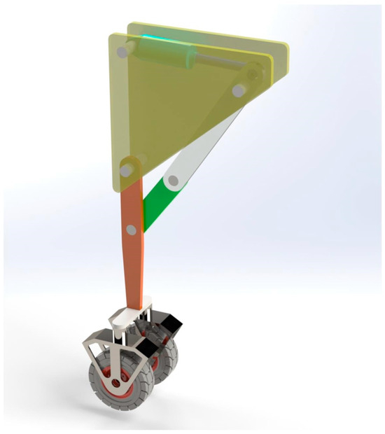
Figure 13.
The auxiliary supporting leg structure.

Figure 14.
6W4L robot model: (a) wheel mode and (b) leg mode.
As shown in Figure 14a, when the 6W4L robot moves on flat terrain, the moving platform of the parallel mechanism is lifted, and only six sets of wheels touch the ground. The robot is in wheel mode, with the auxiliary supporting legs in an extended state and in contact with the ground. The robot can move rapidly, and auxiliary steering devices that control left and right rotation can be installed on the wheels to achieve steering of the mobile robot.
In this state, the mobile robot mainly relies on six wheels for movement. The driving state relies on the support of the end wheels of the auxiliary foldable legs. These two wheels can control the forward and backward steering of the mobile robot, and the folding changes of the auxiliary foldable legs can be controlled by hydraulic pressure. The four moving wheels integrated with the parallel mechanism do not have power devices installed and only play a supporting role. When moving in this state, the square platform above can carry goods, and the load distribution is uniform. Two of the six wheels are located at the front and back, and four are located on the left and right, which also play a role in preventing tipping.
As shown in Figure 14b, when the robot needs to navigate rough terrain or turn, the parallel mechanism feature is utilized. Four sets of 2-UPS&PRPU parallel mechanism moving platforms serve as supporting legs to lift the robot and shift it into leg mode, with the auxiliary supporting legs in a retracted state. In this state, the robot can navigate through complex road conditions. The movement of the parallel mechanism rotates the end platform around the Z-axis to achieve turning of the 6W4L robot.
Due to the retraction of the auxiliary supporting legs, the 6W4L robot relies on four parallel mechanisms to move. Each parallel mechanism is driven by four motors, as shown in Figure 1a, which control the position of the moving platform in space to move the robot. This state requires adjusting the postures of the four parallel mechanisms based on the quality of the transported goods and their position on the square platform. When the robot moves, one of the four parallel mechanisms needs to be lifted, while the other three serve as support. At this time, these three parallel mechanisms must be adjusted to control the robot’s center of gravity such that it is within the range of the triangle formed by the three parallel mechanisms on the moving platform. This characteristic should also be ensured during the movement process, in order to ensure the smoothness of the robot’s movement in this state.
At present, the design of parallel mechanisms applied to wheel-legged robots mostly bundles the moving wheel with the parallel mechanism; that is, the moving wheel is fixed to the moving platform, and the moving wheel changes with the position of the parallel mechanism’s moving platform. This design means that the moving wheels cannot independently support the mobile robot in walking if the parallel mechanism fails. If the moving wheel malfunctions, it will also seriously affect the pose changes in the parallel mechanism. This design integrates the wheel mode and leg mode. When both mobile modes have no faults, switching between them can be achieved. When one mobile mode fails, it does not affect the operation of the other, making the two modes a backup solution for each other and avoiding system failure caused by single-mode failure.
The 6W4L robot was simulated using the parameters set in Section 3.3. The initial distance between the wheel contact surface and the robot’s cargo platform was set to 260 mm. Since θ was set to 60°, this caused a change in the angle α, as shown in Figure 6. At this point, we do not consider the rotation of the parallel mechanism’s end around the X-axis; instead, we only consider the spatial positions that its end center can reach. As shown in Figure 14, the 2-UPS&PRPU parallel mechanism serves as one of the 6W4L robot’s supporting legs, primarily enabling the robot’s forward and backward movements. Therefore, we analyzed the movement of a set of parallel mechanisms within the Y-Z plane.
For the step-path-planning analysis of the robot’s front leg, due to the constraints of the wheeled linkages, the step length along the Y-axis was set to 200 mm, and the step height along the Z-axis was set to 100 mm. The initial position in the Y-Z plane was set to (60, −400). The results were obtained through software simulation and modeling, as shown in Figure 15, which shows the stride path plan. The right front leg of the 6W4L robot performs a stride action along the blue trajectory. Figure 15b moves the proposed stride trajectory into the mechanism’s workspace, indicating that the parallel mechanism can complete the robot’s stride action.
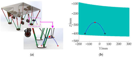
Figure 15.
Stride path planning: (a) the stride path model and (b) the schematic diagram of the stride path within the workspace.
6. Conclusions
We proposed a novel 2-UPS&PRPU parallel mechanism with multi-DOF motion capabilities, which is suitable for movement in complex environments. Firstly, the DOFs of the parallel mechanism were systematically analyzed and verified. After establishing a three-dimensional model and coordinate systems for the parallel mechanism, the closed-loop vector method was used to model and analyze its kinematics. By introducing the motion characteristics of a Hooke joint, the kinematic equations of the mechanism were further derived and, based on this, the Jacobian matrix of the mechanism was solved. Through analysis of the Jacobian matrix, two singular configurations of the mechanism were identified within its workspace. These singular configurations can cause the mechanism to lose its ability to move; thus, they should be avoided as much as possible in practical applications to ensure the stability and safety of the mechanism. Based on the kinematic analysis, combined with the 6W4L robot application scenario, reasonable initial structural parameters were set.
Further analysis was conducted on the workspace of the mechanism under specific postures, evaluating its accessibility and clarifying its applicability and performance boundaries in practical applications. To enhance the overall performance of the mechanism, this study also conducted a systematic analysis of the robot’s agility and load-bearing capacity. Its motion transmission performance was evaluated and optimized by introducing evaluation indicators, such as linear velocity agility and minimum output carrying capacity. The optimization results showed that, through reasonable design, the mechanism presented significantly improved dynamic response capability and load adaptability while maintaining a compact structure.
Finally, the potential application of the 2-UPS&PRPU parallel mechanism in practical engineering was discussed. This mechanism can serve as a mobile robot leg, effectively enhancing the obstacle-crossing capability and motion stability of such robots under rugged terrain conditions, thus presenting good engineering application prospects.
Author Contributions
Conceptualization, W.H.; methodology, W.H., L.Z., and R.L.; validation, W.H., W.G., and F.N.; formal analysis, W.H.; investigation, W.H.; resources, R.L.; writing—original draft preparation, W.H.; writing—review and editing, W.H.; visualization, W.H.; supervision, R.L.; funding acquisition, R.L. All authors have read and agreed to the published version of the manuscript.
Funding
This research was funded by the Key Research and Development Program of Shanxi Province of China, grant number 202202150401018, and supported by the Opening Foundation of the Shanxi Key Laboratory of Advanced Manufacturing Technology, grant number XJZZ202105.
Institutional Review Board Statement
Not applicable.
Informed Consent Statement
Not applicable.
Data Availability Statement
The raw data supporting the conclusions of this article will be made available by the authors upon request.
Conflicts of Interest
Author Wenxiao Guo was employed by the company CCTEG Taiyuan Research Institute Co., Ltd. The remaining authors declare that the research was conducted in the absence of any commercial or financial relationships that could be construed as a potential conflict of interest.
Abbreviations
The following abbreviations are used in this manuscript:
| DOF | Degree of freedom |
| LCIV | Local linear velocity dexterity index |
| LCIω | Local angular velocity dexterity index |
| GCIV | Global comprehensive index of velocity |
| GFI | Goodness-of-fit index |
References
- Bi, W.; Xie, F.; Liu, X.-J.; Luo, X. Optimal Design of a Novel 4-Degree-of-Freedom Parallel Mechanism with Flexible Orientation Capability. Proc. Inst. Mech. Eng. B J. Eng. Manuf. 2019, 233, 632–642. [Google Scholar] [CrossRef]
- Diego, P.; Macho, E.; Herrero, S.; Campa, F.J.; Diez, M.; Corral, J.; Pinto, C. Kinematic and Workspace Analysis of RRU-3RSS: A Novel 2T2R Parallel Manipulator. Appl. Sci. 2024, 14, 9491. [Google Scholar] [CrossRef]
- Guo, F.; Wang, S.; Yue, B.; Wang, J. A Deformable Configuration Planning Framework for a Parallel Wheel-Legged Robot Equipped with Lidar. Sensors 2020, 20, 5614. [Google Scholar] [CrossRef]
- Guo, T.; Liu, J.; Liang, H.; Zhang, Y.; Chen, W.; Xia, X.; Wang, M.; Wang, Z. Design and dynamic analysis of jumping wheel-legged robot in complex terrain environment. Front. Neurorobot. 2022, 16, 1066714. [Google Scholar] [CrossRef]
- Feller, D. Kinematics of a Novel Serial-Parallel, Compliant, Three-Legged Robot. IEEE Access 2023, 11, 100729–100754. [Google Scholar] [CrossRef]
- Li, L.; Wang, C.; Wu, H. Research on Kinematics and Pouring Law of a Mobile Heavy Load Pouring Robot. Math. Probl. Eng. 2018, 2018, 8790575. [Google Scholar] [CrossRef]
- Jia, S.; Chen, W.; Zhang, W.; Wu, H.; Li, W. Kinematics Analysis of Walking Robot Based on Double Stewart Parallel Mechanism. In Proceedings of the 2019 Chinese Automation Congress (CAC), Hangzhou, China, 22–24 November 2019; pp. 5530–5535. [Google Scholar]
- Martínez, O.; Soto, I.; Campa, R. Mathematical Modeling of a 3-CUP Parallel Mechanism Using the Fermat Point. Mech. Mach. Theory 2021, 161, 104326. [Google Scholar] [CrossRef]
- Niu, J.; Wang, H.; Jiang, Z.; Chen, L.; Zhang, J.; Feng, Y.; Guo, S. Kinematic Analysis of a Serial-Parallel Hybrid Mechanism and Its Application to a Wheel-Legged Robot. IEEE Access 2020, 8, 111931–111944. [Google Scholar] [CrossRef]
- Li, L.; Fang, Y.; Yao, J.; Wang, L. Type Synthesis of a Family of Novel Parallel Leg Mechanisms Driven by a 3-DOF Drive System. Mech. Mach. Theory 2022, 167, 104572. [Google Scholar] [CrossRef]
- Zhang, J.; Jin, Z.; Zhao, Y. Dynamics Analysis of Leg Mechanism of Six-Legged Firefighting Robot. J. Mech. Sci. Technol. 2018, 32, 351–361. [Google Scholar] [CrossRef]
- Rodriguez, E.; Riaño, C.; Alvares, A.; Bonnard, R. Design and Dimensional Synthesis of a Linear Delta Robot with Single Legs for Additive Manufacturing. J. Braz. Soc. Mech. Sci. Eng. 2019, 41, 536. [Google Scholar] [CrossRef]
- Sang, L.; Wang, H.; Yu, H.; Vladareanu, L. A Novel Human-Carrying Quadruped Walking Robot. Int. J. Adv. Rob. Syst. 2017, 14, 172988141771659. [Google Scholar] [CrossRef]
- Wu, Y.; Guo, S.; Li, L.; Niu, L.; Li, X. Design of a Novel Side-Mounted Leg Mechanism with High Flexibility for a Multi-Mission Quadruped Earth Rover BJTUBOT. Front. Mech. Eng. 2023, 18, 24. [Google Scholar] [CrossRef]
- Xu, Y.; Liang, Z.; Liu, J. A New Metamorphic Parallel Leg Mechanism with Reconfigurable Moving Platform. Math. Probl. Eng. 2020, 2020, 3234969. [Google Scholar] [CrossRef]
- Zhang, Y.; Zang, X.; Chen, B.; Zhang, X.; Liu, Y.; Zhao, J. Type Synthesis of a Novel 4-Degrees-of-Freedom Parallel Bipedal Mechanism for Walking Robot. Adv. Intell. Syst. 2024, 6, 2300384. [Google Scholar] [CrossRef]
- Zhao, J.; Liu, K.; Zhao, F.; Sun, Z. Design and Kinematic Analysis on a Novel Serial-Parallel Hybrid Leg for Quadruped Robot. In Proceedings of the Intelligent Robotics and Applications, Shenyang, China, 8–11 August 2019; Yu, H., Liu, J., Liu, L., Ju, Z., Liu, Y., Zhou, D., Eds.; Springer International Publishing: Cham, Switzerland, 2019; pp. 436–447. [Google Scholar]
- An, Z.; Zhou, Z.; Li, D.; Gao, Z. Dynamic Behaviors of an Integrated Crawler Mobile Parallel Robot in Obstacle-Crossing. Nonlinear Dyn. 2023, 111, 16939–16962. [Google Scholar] [CrossRef]
- Li, Y.; Yao, Y.; He, Y. Design and Analysis of a Multi-Mode Mobile Robot Based on a Parallel Mechanism with Branch Variation. Mech. Mach. Theory 2018, 130, 276–300. [Google Scholar] [CrossRef]
- Zhao, F.-Q.; Guo, S.; Su, H.-J.; Qu, H.-B.; Chen, Y.-Q. Design of Self-Reconfigurable Multiarm Robot Mechanism Based on Deployable Kinematic Chains. Chin. J. Mech. Eng. 2020, 33, 70. [Google Scholar] [CrossRef]
- Niu, J.; Wang, H.; Shi, H.; Pop, N.; Li, D.; Li, S.; Wu, S. Study on Structural Modeling and Kinematics Analysis of a Novel Wheel-Legged Rescue Robot. Int. J. Adv. Rob. Syst. 2018, 15, 1729881417752758. [Google Scholar] [CrossRef]
- Ping, A.; Zhang, C.; Yang, J. Design and Kinematic Analysis of New Multi-Mode Mobile Parallel Mechanism with Deployable Platform. Ind. Robot. Int. J. Robot. Res. Appl. 2022, 49, 885–902. [Google Scholar] [CrossRef]
- Ushimi, N. A Concept and Development of a Four Wheeled Reconfigurable Mobile Robot by Parallel Linkage Mechanism and an Influence of a Driving Wheel Sideslip on Grassy Slopes. In Proceedings of the 2019 19th International Conference on Control, Automation and Systems (ICCAS), Jeju, Republic of Korea, 15–18 October 2019; pp. 1549–1553. [Google Scholar]
- Zhao, C.; Guo, W. Inverted Modelling: An Effective Way to Support Motion Planning of Legged Mobile Robots. Chin. J. Mech. Eng. 2023, 36, 19. [Google Scholar] [CrossRef]
- Pan, Y.; Gao, F. Position Model Computational Complexity of Walking Robot with Different Parallel Leg Mechanism Topology Patterns. Mech. Mach. Theory 2017, 107, 324–337. [Google Scholar] [CrossRef]
- Hao, R.; Guo, C.; Han, Z.; Han, Y. Design and Research of Single Leg Walking Mechanism of Quadruped Robot. Vibroengineering Procedia 2023, 49, 130–135. [Google Scholar] [CrossRef]
- Chamas, M.H.; Amine, S.; Gazo Hanna, E.; Mokhiamar, O. Control of a Novel Parallel Mechanism for the Stabilization of Unmanned Aerial Vehicles. Appl. Sci. 2023, 13, 8740. [Google Scholar] [CrossRef]
- Liu, R.; Yao, Y. A Novel Serial–Parallel Hybrid Worm-like Robot with Multi-Mode Undulatory Locomotion. Mech. Mach. Theory 2019, 137, 404–431. [Google Scholar] [CrossRef]
- Tazaki, Y. Parallel Link-Based Light-Weight Leg Design for Bipedal Robots. In Proceedings of the 2019 IEEE-RAS 19th International Conference on Humanoid Robots (humanoids), Toronto, ON, Canada, 15–17 October 2019; pp. 565–571. [Google Scholar]
- Xu, K.; Ding, X. Gait Analysis of a Radial Symmetrical Hexapod Robot Based on Parallel Mechanisms. Chin. J. Mech. Eng. 2014, 27, 867–879. [Google Scholar] [CrossRef]
- Liu, J.; Chen, Z.; Gao, F. Kinematic Calibration of a Six-Legged Walking Machine Tool. Chin. J. Mech. Eng. 2022, 35, 34. [Google Scholar] [CrossRef]
- Fu, J.; Gao, F. Dynamic Stability Analyzes for a Parallel–Serial Legged Quadruped Robot. Int. J. Adv. Rob. Syst. 2022, 19, 172988062211320. [Google Scholar] [CrossRef]
- Pan, Y.; Gao, F.; Du, H. Fault Tolerance Criteria and Walking Capability Analysis of a Novel Parallel-Parallel Hexapod Break Walking Robot. Robotica 2016, 34, 619–633. [Google Scholar] [CrossRef]


Disclaimer/Publisher’s Note: The statements, opinions and data contained in all publications are solely those of the individual author(s) and contributor(s) and not of MDPI and/or the editor(s). MDPI and/or the editor(s) disclaim responsibility for any injury to people or property resulting from any ideas, methods, instructions or products referred to in the content. |
© 2025 by the authors. Licensee MDPI, Basel, Switzerland. This article is an open access article distributed under the terms and conditions of the Creative Commons Attribution (CC BY) license (https://creativecommons.org/licenses/by/4.0/).