Abstract
A cable-driven hybrid mobile robot is a kind of robot consisting of two modules connected in series, which uses multiple parallel cables to drive the moving platforms. Cable-driven robots benefit from a large workspace, low inertia, excellent dynamic performance due to the lightweight and high extensibility of cables, making them ideal for a wide range of applications, such as sports cameras, large radio telescopes, and planetary exploration. Considering the fundamental dynamic constraint imposed by the unilateral constraint of cables, the workspace and dynamic modeling for cable-driven robots require specialized study. In this paper, a novel cable-driven hybrid robot, which has two motion patterns, is designed, and an arc intersection method for analyzing workspace is applied to solve the robot workspace of two motion patterns. Based on the workspace analysis, a dynamic model for the cable-driven hybrid robot is established, laying the foundation for subsequent trajectory planning. Simulation results in MATLAB R2021a demonstrate that the cable-driven hybrid robot has a large workspace in both motion patterns and is capable of meeting various motion requirements, indicating promising application potential.
1. Introduction
A cable-driven hybrid robot is a type of cable-driven robot, utilizing multiple parallel cables to apply both driving and constraint forces to the moving platforms. The fully actuated cable-driven hybrid robot studied in this paper maintains tension in all cables through the support force provided by the intermediate piston rod and the constraining force from inextensible cables. Unlike redundantly actuated cable-driven robots that rely on internal forces generated by redundant parallel cables, fully actuated cable-driven robots do not depend on such forces to maintain tension. Cables are lightweight and have a high extensibility ratio, which gives cable-driven robot the advantages of large workspace, low inertia, and excellent dynamic performance. Due to these excellent characteristics, cable-driven robots have extensive applications in various fields, including sports cameras, large radio telescopes, and planetary exploration.
Research on cable-driven robots dates back to the RoboCrane robot [1] developed by the U.S. National Institute of Standards and Technology (NIST) in 1989. This robot features an inverted Gough-Stewart platform configuration whose moving platform is driven by six parallel cables, distinguishing it from traditional Stewart platforms, which are driven by rigid links. After many years of development, the RoboCrane robot has been applied in various fields such as aircraft maintenance and construction. The Skycam [2,3], a large cable-suspended parallel robot, is a famous application of cable-driven robots. It is usually placed above stadiums for live streaming of sports events, such as the 2022 FIFA World Cup. The FAST (Five-hundred-meter Aperture Spherical Telescope) proposed by Duan et al. [4,5,6] is another significant application of cable-driven robots. The FAST employs a cable-suspended parallel robot driven by six parallel cables, along with a 6-DoF parallel robot suspended from the CSPR’s moving platform, to achieve high-precision positioning of the radio tele-scope’s receiver over a large range. This application highlights the advantage of cable-driven robots in large workspace. Cable-driven robots also play a significant role in planetary exploration. The NASA Super Ball Bot [7,8,9], an all-in-one landing and mobility platform based on tensegrity structures, enables lower-cost and more reliable planetary missions. The Super Ball Bot features a spherical structure of cables and joints, capable of withstanding being dropped from a spacecraft over a planetary surface and bouncing upon impact. The lighter weight and maneuverability of the Super Ball Bot could make it possible to carry out an exploration mission on that planet, which has a soft planetary surface more like a hazardous marsh with lakes of liquid methane that would not be suitable for a traditional rover that could sink down and get stuck.
Researchers typically employ the wrench equilibrium equations of the moving platform to map unilateral force constraints in the joint space to the robot workspace [10,11,12,13,14,15,16]. Under given topological structures and geometric parameters, the workspace of cable-driven parallel robots can be analyzed based on these wrench equilibrium equations [17,18,19]. Wrench-feasible workspace is a crucial concept for analyzing cable-driven parallel robots [20,21,22]. It is commonly used to determine the set of feasible poses of the moving platform within specified tension ranges and wrench ranges. This directly corresponds to the robot’s effective workspace under specific end-effector load requirements and cable-driven capabilities. Efficient computation of the wrench-feasible workspace can be achieved using various methods. Merlet et al. proposed a novel approach using interval analysis [23] and branch-and-prune algorithms [24,25] to efficiently compute the wrench-feasible workspace of parallel cable-driven robots. This method avoids discretization errors and provides guaranteed results by testing feasibility conditions on continuous domains. Gosselin et al. [26,27] presented an algorithm for determining the workspace of 6-degree-of-freedom parallel manipulators, focusing on their positioning capabilities. The method leveraged geometric properties of the workspace, derived from the inverse kinematics [28,29,30,31,32,33], to describe regions in three-dimensional space that the manipulator [34,35,36,37] can reach with a specified platform orientation.
Inspired by existing works of scholars [38,39,40,41,42,43,44], this paper applies the method proposed by Gosselin to determine the workspace of our novel 6-DoF multi-pattern cable-driven hybrid robot. It is noted that the workspace is obtained geometrically, which is the positioning workspace, i.e., the region that can be attained by the ending platform with a given orientation. The workspace obtained geometrically is larger than the wrench-feasible workspace, yet it encompasses most of the wrench-feasible workspace. Thus, it provides guidance and establishes the foundation for determining the wrench-feasible workspace subsequently.
The outline of this paper is as follows. After a brief review of research on cable-driven robots and robot workspace in Section 1, a novel multi-pattern cable-driven hybrid robot is proposed, and the dynamic modeling of the multi-pattern cable-driven hybrid robot is established in Section 2. The robot workspaces are determined in Section 3 before summarizing conclusions in Section 4.
2. Methods and Materials
2.1. Robot Architecture
In this section, a brief description of the multi-pattern cable-driven robot is presented, and more details can be found in our previous works [45,46,47].
The multi-pattern cable-driven robot consists of four platforms, which are called platform A, platform B, platform C, and platform D, respectively; twelve cables; and two piston rods. There are three pairs of electromagnets in each platform to switch between the prismatic motion pattern and pyramidal motion pattern. The robot architecture is illustrated in Figure 1.
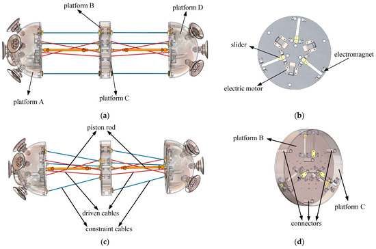
Figure 1.
(a) Robot architecture of prismatic motion pattern; (b) Inside structure of platforms A and D; (c) Robot architecture of pyramidal motion pattern; (d) Inside structure of platforms B and C.
In Figure 1a,c, it is evident that the robot is composed of two identical parallel mechanisms connected in series, and each module consists of a hemispherical platform and a circular platform. Between the two platforms, the blue inextensible constraint cables, red drive cables, and orange piston rod are connected in parallel, so the cable-driven robot is a hybrid robot. Besides, there are several suction cups on the outer surfaces of the hemispherical platforms to provide suction force. Figure 1b shows the internal structure of platforms A and D, and platforms B and C shown in Figure 1d are identical to A but lack three electric motors. When three sliders in each platform are simultaneously attracted by the outer or inner electromagnets, the robot is in prismatic motion pattern, as illustrated in Figure 1a, and the robot is in the pyramidal pattern if sliders in platforms A and D are attracted by the outer electromagnets, while sliders in platforms B and C are attracted by the inner electromagnets shown in Figure 1c.
The details of physical implementation are presented here to provide a clearer understanding of the robot architecture. The 24V planetary gear DC brushless reducer motor is chosen for its robust performance, with a power rating of 15 W, a rotational speed of 8 RPM, and a torque of 0.55 kg*m. These specifications ensure precise control and sufficient power for the intended applications. Six 24V DC miniature electromagnets are employed, each providing a holding force of 2 kg. Additionally, three electromagnet remote switches are integrated to facilitate precise control of the electromagnets during operation. A 24V miniature electric linear actuator is selected for the piston rod, offering a thrust of 50 N and a linear speed of 15 mm/s. This choice ensures smooth and accurate movement of the mechanism. The constraint cables are made of inextensible steel wires, while the drive cables are selected as nylon ropes. These choices are based on their respective mechanical properties to ensure reliability and durability in the system.
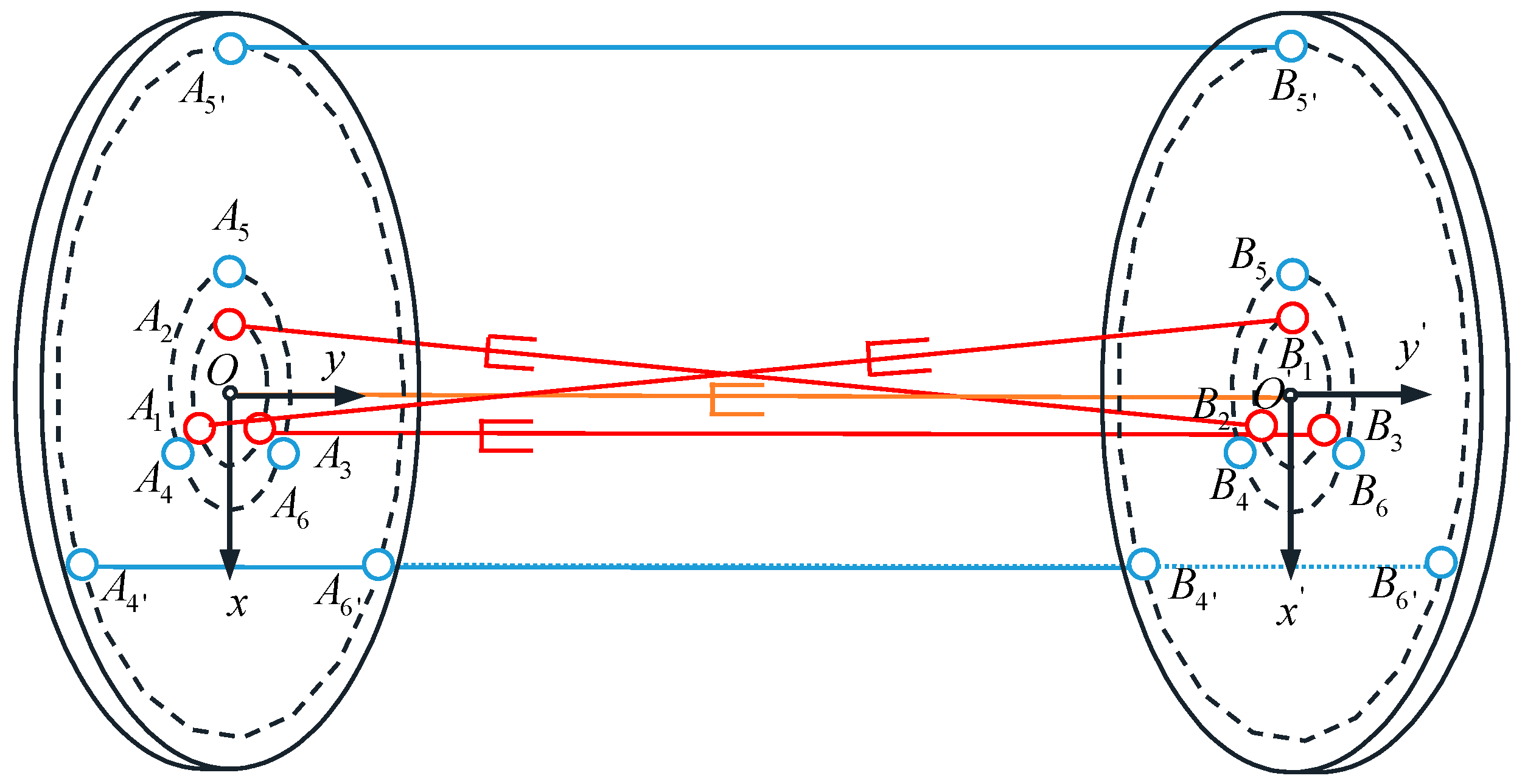
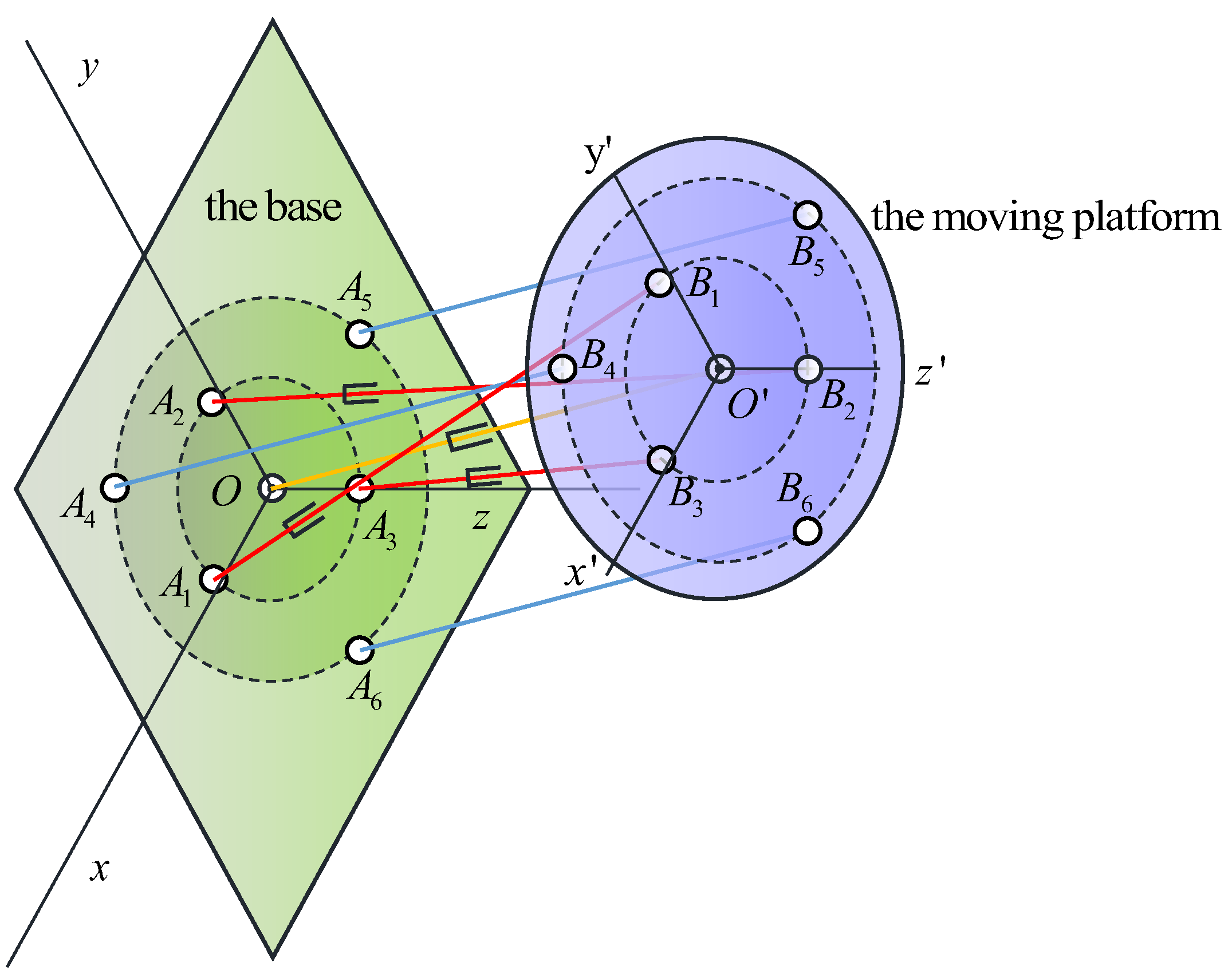
Before beginning the analysis of the robot workspace, let us consider establishing the most suitable coordinate frames according to the robot’s unique architecture. Clearly, the robot is composed of two identical parallel mechanisms connected in series. However, analyzing the entire robot would be quite complex. Therefore, this paper selects one parallel mechanism of the robot to establish the coordinate frames and analyze the workspace. Let us consider the mechanism composed of platforms A and B, whose mobile platform B is driven by three red cables and constrained by three blue cables, together with a fixed coordinate frame (O, x, y, z) and a mobile coordinate frame (O’, x’, y’, z’), the latter being attached at the platform reference point O’, as shown in Figure 2. The point of the fixed platform A from which cable i extends is denoted Ai, whereas Bi denotes the point of the platform B at which cable i is attached. It is noted that the points (i = 1, 2, 3) are where the drive cables are attached, whereas the points (i = 4, 5, 6) are the constraint cables attached at. Besides, the constraint cables can be positioned at different points according to the robot motion patterns. For example, the constraint cables extend from points Ai or Ai’ (i = 4, 5, 6), and are attached to the corresponding points Bi or Bi’ (i = 4, 5, 6) in the prismatic motion pattern, while the constraint cables extend from Ai points (i = 4, 5, 6), but attached to the corresponding Bi’ (i = 4, 5, 6) points in the pyramidal motion pattern. The axes of z and z’ are not shown in Figure 2, but their directions are determined by a right-handed system.
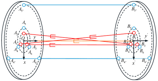
Figure 2.
Schematic diagram of the coordinate frames.
In this robot, the constraint cables are SS (two spherical joints) limbs, the actuation cables are SPS limbs (two spherical joints and one prismatic joint), and the piston rods that maintain cable tension are also SPS limbs. Therefore, the workspace analysis in the next section will be based on this configuration as shown in Figure 2.
2.2. Workspace Analysis
This section provides a brief overview of the arc intersection method as used in the paper. Then, the method is applied to determine the workspace of the robot.
2.2.1. The Intersection of Circles in 2D
The intersection of circles in 2D is considered first to provide a theoretical foundation for subsequent arc intersection in 3D.
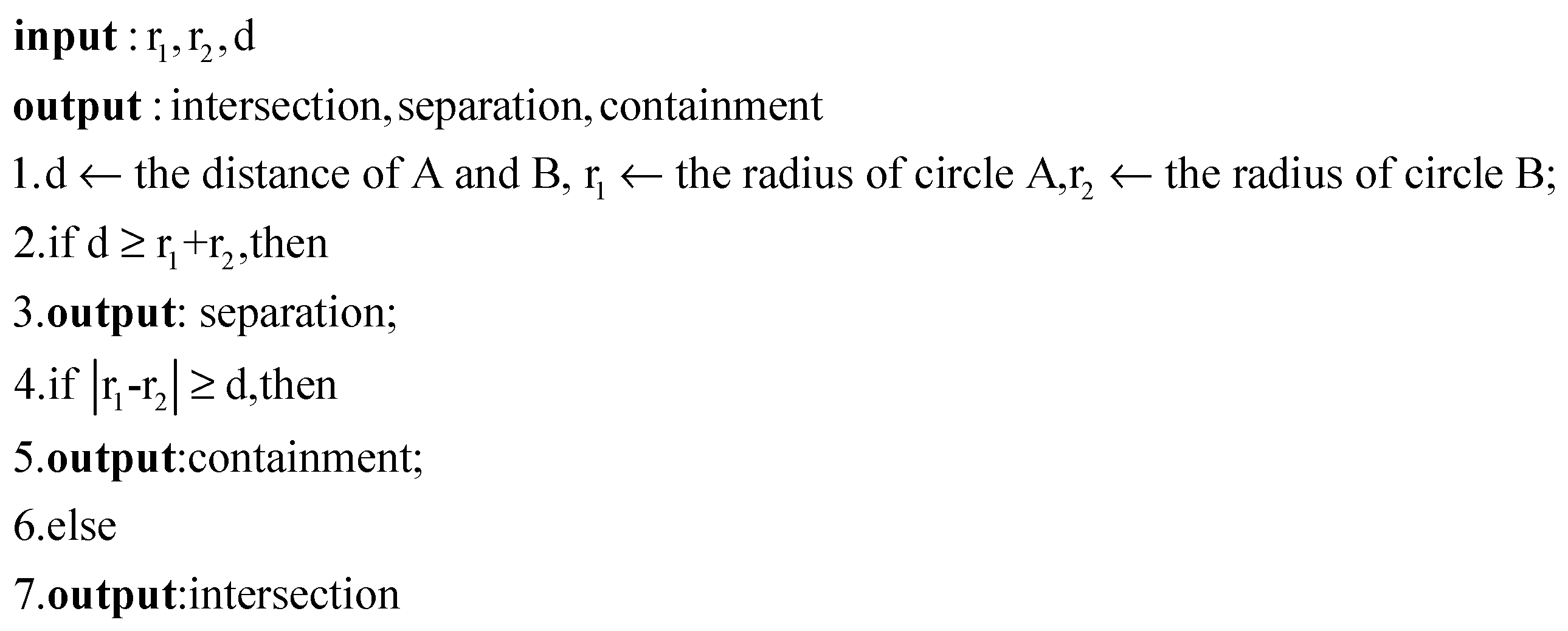
The positional relationships between two circles are categorized into three cases: intersection, separation (including external tangency), and containment (including internal tangency). When the coordinates of the centers and the radii of the two circles are provided, we can determine their intersection status by analyzing the distance between the centers and the radii of the two circles. The pseudocode for this process is shown in Figure 3.
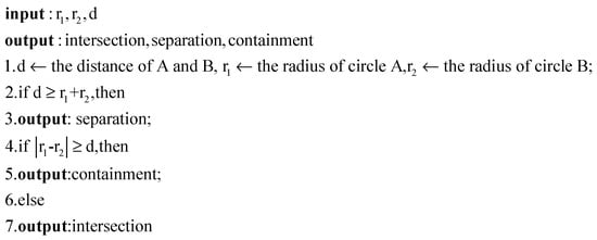
Figure 3.
Pseudocode to determine positional relationships of circles.
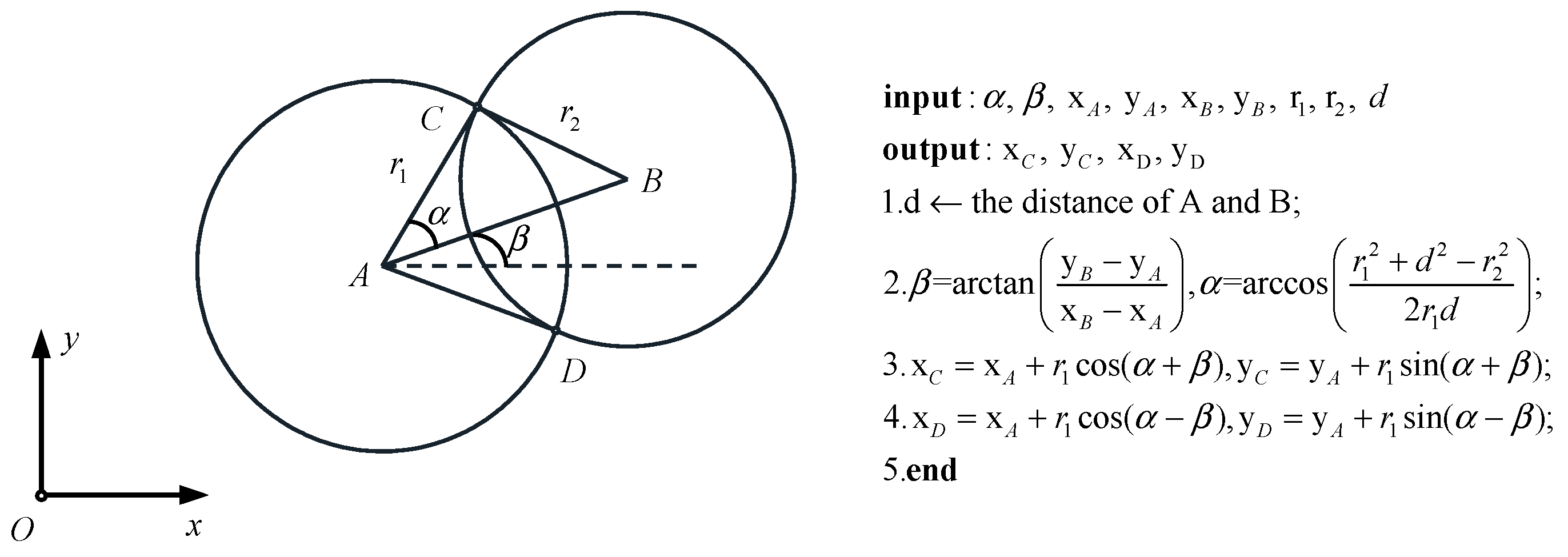
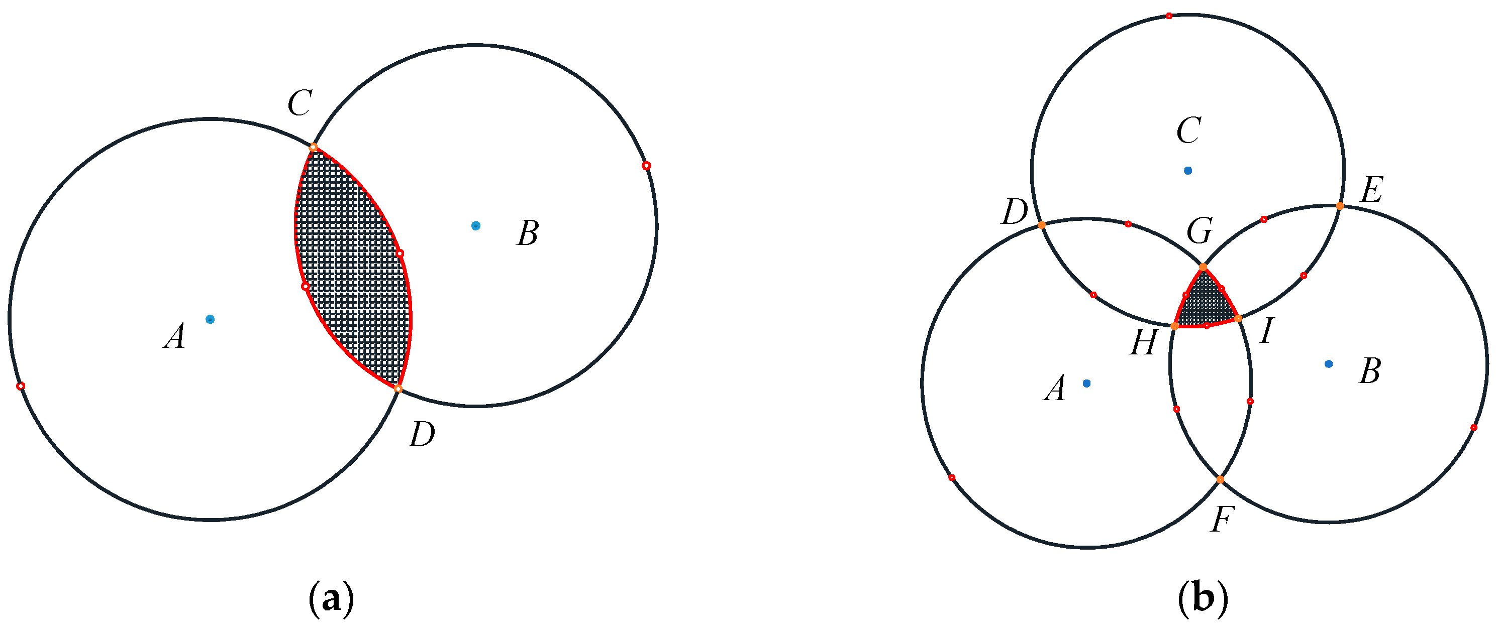
When the two circles intersect at two distinct points, a geometric method can be employed to solve for these intersecting points. The solution process and algorithm are illustrated in Figure 4. Once the intersecting points are identified, the next step is to determine the overlapping region of the two circles. When two circles intersect at two points, they divide each circle into two arcs. Similarly, if there are three points, they can divide a circle into three arcs. In the case of intersecting circles, there are two arcs that form the overlapping region. We can select a test point midway along each arc to check if it lies within the overlapping region. If the point satisfies the condition of the distances to both circle centers being smaller than their respective radii, it indicates that the arc containing this test point forms the boundary of the overlapping region (i.e., the overlapping arc). By iterating through all test points on both circles, we can identify all overlapping arcs. The process of determining intersecting arcs of two circles is shown in Figure 5a.
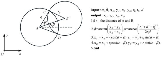
Figure 4.
Pseudocodes to solve for intersection points.
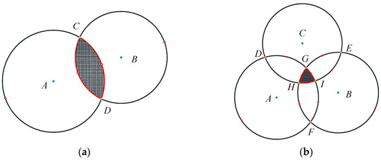
Figure 5.
(a) The intersecting arcs of two circles; (b) The intersecting arcs of multiple circles.
It is important to note that when two circles are separated or one is entirely contained within the other, there are no intersecting points. In such cases, the entire circle can be treated as a single arc. When there are no intersecting points on the circles, we can add a test point and then iterate through these test points to determine the boundaries of the overlapping region. Multiple circles intersection can be handled using the same method. First, iterate over all the circles to calculate pairwise intersection points and determine test points on each circle based on these intersecting points. Then, iterate over all the circles again to verify whether each test point satisfies the required conditions (i.e., being closer to both circle centers than their respective radii). If it satisfies the condition, the arc corresponding to that test point represents an overlapping boundary. The process of determining intersecting arcs of multiple circles is shown in Figure 5b.
2.2.2. The Intersection of Circular Rings in 2D
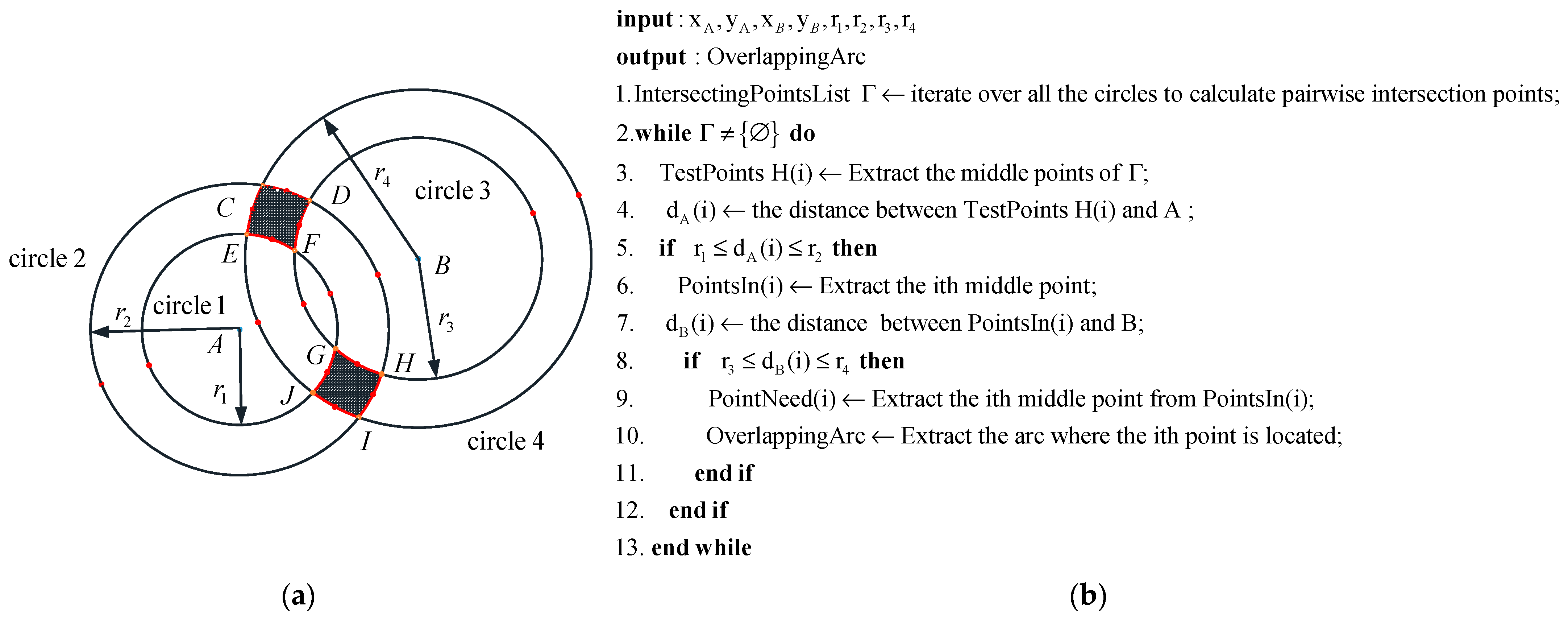
After resolving the problem of determining the intersection of circles, let us now consider the case of intersecting rings. A circular ring consists of two concentric circles, i.e., an inner circle and an outer circle. By treating each ring as two separate circles, the problem of finding the intersection arcs between two rings can be transformed into the problem of determining intersecting arcs among four circles. The process of determining intersecting arcs of rings is similar to the process of determining intersecting arcs of multiple circles in Section 2.2.1. Take two intersecting rings as an example, as shown in Figure 6a. First, iterate over all the circles to calculate pairwise intersecting points and determine test points on each circle based on these intersecting points. Then, iterate over all the circles again to verify whether each test point satisfies the required conditions. If a test point satisfies the conditions, the arc corresponding to that point represents an overlapping boundary (overlapping arc). It is emphasized that the conditions for determining test points differ between the outer and inner circles. For the outer circle, the distance from the test point to the center of the circle should be less than or equal to the radius of the outer circle. For the inner circle, the distance from the test point to the center of the circle should be greater than or equal to the radius of the inner circle. The pseudocode for the process is illustrated in Figure 6b.
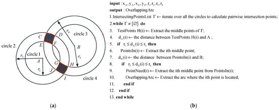
Figure 6.
(a) The intersecting arcs of two rings; (b) pseudocode to solve for intersection points.
2.2.3. The Arc Intersection Method for the Workspace
Based on the theoretical foundation of the 2D arc intersection method, we introduce the 3D arc intersection method in this subsection and applied it to determine the workspace of a parallel mechanism module in this cable-driven robot.
Regardless of how the parallel mechanism moves, the distance from the center of the moving platform to the connection point with the limb remains constant. Now, focusing on a single limb, assume that the limb is connected to a spherical joint at the stationary platform, without considering the joint’s range of motion limitations. If the limb is allowed to move freely, the end of the limb sweeps out a spherical area in space. Considering the maximum and minimum extensions of the limb, the end of the limb sweeps out an annular region between two spheres: the outer sphere has a radius equal to the maximum length of the limb (lmax), while the inner sphere has a radius equal to the minimum length (lmin). The region swept by the limb is illustrated in Figure 7a. In the meantime, moving the sphere along the vector connecting the moving platform joint of the limb to the center of the moving platform results in the red sphere shown in Figure 7b. This red spherical region represents the range of motion of the moving platform’s center point under the constraint of a single limb. Multiple spheres are obtained by performing the same operation on the other limbs, and the intersection of these spheres represents the range of motion of the center point of the parallel mechanism, which corresponds to its workspace.
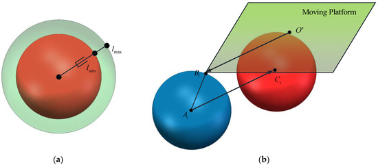
Figure 7.
(a) The region swept by the limb; (b) locations of the centers of spheres used to determine the workspace.
There are two methods to determine the intersection of these spheres. The first method employs SolidWorks 2023 software for sphere intersection operations, which is intuitive, straightforward, and easily yields the volume of the workspace. However, this approach does not provide functional expressions for the boundaries of a specific cross-section of the workspace. The second method, proposed by C. Gosselin, involves slicing the spheres along the z-axis from bottom to top. This transforms the three-dimensional sphere intersection problem into a two-dimensional circular ring intersection problem. While this method enables the derivation of specific functional expressions for a particular cross-section, it complicates the calculation of the workspace volume. The second method is applied in this paper for the following determination of the cable-driven robot workspace.
In order to better solve the workspace of the robot, we give a simplified schematic of one parallel mechanism of the cable-driven robot, as shown in Figure 8. The coordinate frames and notations of Ai and Bi are the same as those in Figure 2, R: O-xyz is the fixed coordinate frame attached to the base of the robot, and R’: O’-x’y’z’ is the moving coordinate frame attached to the moving platform. Therefore, vectors (i = 1, …, 6) will be defined as the position vectors of joints on base, which are constant vectors expressed in frame R, and vectors will be defined as the position vectors of joints on the moving platform, which are constant vectors expressed in frame R’. Here, we define the matrix Q to be the rotation matrix describing the orientation of R’ with respect to R, i.e., Q is the position matrix of the moving platform relative to the base at the initial position. If the position vector of the moving platform center O’ expressed in the fixed coordinate frame R is , then the position vectors of the points Bi expressed in the fixed coordinate frame R are as follows:
where the subscript outside of the brackets specifies the coordinate frame in which the vector is expressed. The position vectors AiBi expressed in the fixed coordinate frame are as follows:

Figure 8.
Simplified schematic of the cable-driven robot.
The left-hand side of Equation (2) represents the vector along the ith limb connecting point A to point B. If we take the Euclidean norm of both sides of the equation, we can derive the magnitude, which corresponds to the length of the limb i, i.e.,
Consequently, for a given limb, where the positions of the joints on both the base and the platform are specified, and with prescribed values for the platform’s position and orientation, the required limb lengths can be directly computed using Equation (3). Notably, this equation provides the solution to the inverse kinematic problem. Equation (3) can be expressed as follows:
where the following is true:
where represents the (i,j) entry of the rotation matrix Q, and where the parameters utilized in Equation (5) are defined as follows:
For a given limb length , the boundary of the workspace of limb i can be determined as the set of points for which we have the following:
Then, the equations for the inner and outer spheres of each limb can be obtained:
where , , are the coordinates of the center of the sphere formed by the endpoints of the ith limb after translation along vector BiO’. For a parallel mechanism with given structural parameters and initial posture, , , are determined.
A portion of the workspace can be derived by sectioning the aforementioned spheres, specifically by finding their intersection with a plane. This results in multiple pairs of concentric circles. For example, to determine the workspace section on a plane parallel to the xoy plane, defined by z = zD, Equation (8) is rewritten as follows:
where the following is true:
and determine the radii of the concentric circles, respectively. It is emphasized that the case where spheres do not intersect the given plane is taken into account according to Equations (9) and (10).
Similarly, the workspace section on a plane parallel to the yoz plane, defined as x = xD, can be obtained in the same way. Then, Equation (8) is rewritten as follows:
where the following is true:
2.3. Dynamic Modeling
After determining the workspace of the cable-driven robot, the equations that govern the dynamics of one parallel mechanism module of the cable-driven robot are formulated in this section.
The robot architecture is illustrated in Section 2.1, with the symbols denoted in Section 2.1 and Section 2.2.3, unless specified otherwise. The inverse kinematic equation is presented in Equation (3), and is the effective cable length, given by Equation (4). The dynamic model of the cable-driven robot is built with the Newton-Euler approach, which yields the following:
where is the force provided by the piston rod, is the vector of gravitational acceleration, is the tension in the ith cable, and I is the inertial tensor of the platform around O’ with respect to the moving frame R’, i.e.,
Then, Equation (13) can be rewritten as follows:
where is the cable tension-to-length radio, which must remain positive to ensure that the cables remain taut during motions of the robot. The vector of cable tension can be rewritten as follows:
It is noted that Equation (16) is the condition to determine the wrench-feasible workspace of the cable-driven robot, where cables remain taut all the time. Equation (16) indeed defines the vector of cable tensions, which is a crucial step in determining the wrench-feasibility workspace. The wrench-feasibility condition arises from the requirement that all cable tensions must be greater than zero to maintain the tautness of the cables during robot motion. Equation (16) provides the mathematical relationship between the cable tensions and the resultant wrench, but it is the additional constraint that all tensions must be positive. The wrench-feasible workspace of our cable-driven robot will be explored in our future work.
A cable-driven robot can be viewed as a set of undamped mass-spring systems, which aids in understanding its behavior and supporting trajectory planning. Specifically, each drive cable can be modeled as a spring of stiffness ki with zero free length, thereby enabling the entire system of one parallel robot module to be represented as a platform driven by three springs and constrained by three cables. Applying Equations (13)–(16), the dynamic equations for the system can be written as follows:
where is the resultant cable force, ki is the stiffness of the ith equivalent spring, which has zero free length. In other words, the force in the ith spring is zero if is equal to zero. The schematic diagram of the robot dynamic model is shown in Figure 9. In the dynamic model, the drive cables have the same stiffness, and the constraint cables have the same stiffness, but the stiffness of drive cables differs from that of the constraint cables (i.e., , , .) The tension on the cables, the supporting force provided by the piston rod, and the gravity of the platform together determine the speed and acceleration of the platform. The wrenches of tension on the geometric center of the moving platform O’ determine the angular velocity of the moving platform.
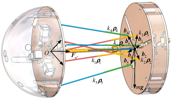
Figure 9.
Schematic diagram of the robot dynamic model.
The purpose of the preliminary dynamic model is to guide trajectory planning for the active robot. If natural free-motion trajectories can be identified for the dynamic model, it guarantees that these trajectories can be executed by the robot while maintaining cable tension, provided that the actuator’s torque and velocity limits are respected.
3. Results
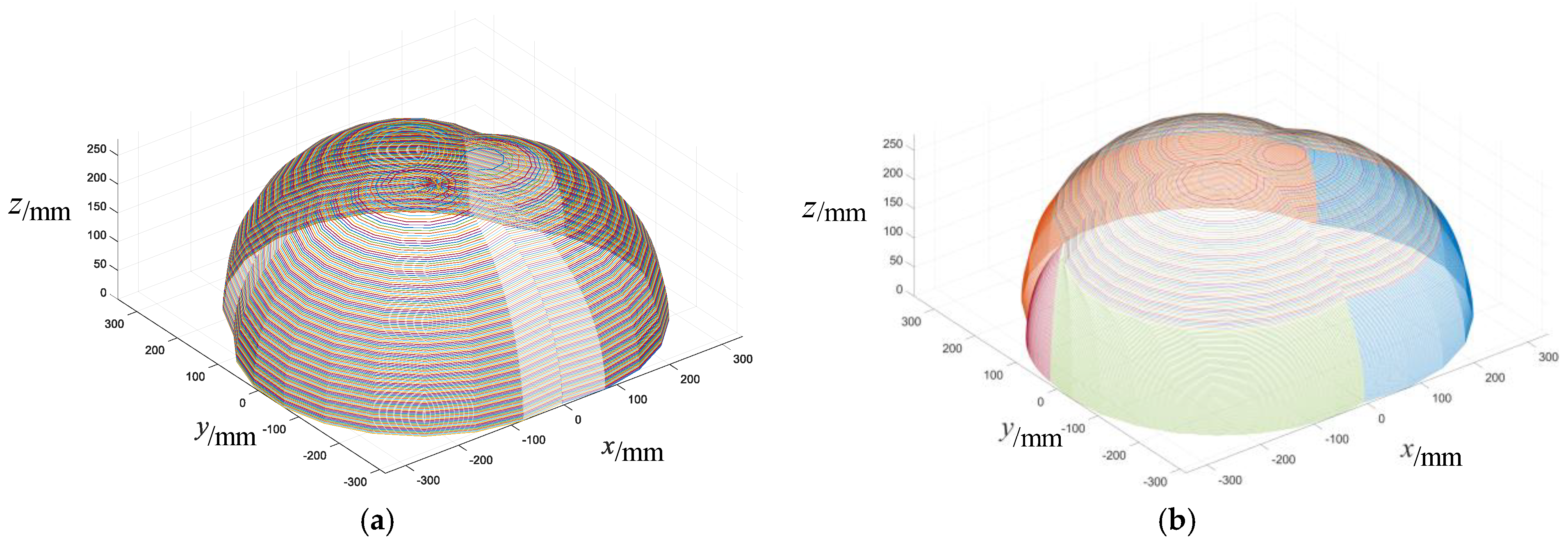
A portion of the workspace can be determined by finding the intersection of seven annular regions, that is, areas bounded by concentric circles. For example, we give the workspace in two different motion patterns of the cable-driven mobile robot determined by this method, as shown in Figure 10. It is important to note that the workspace of the piston rod in this paper is equivalent to the workspace of one drive cable. When the piston rod has a stroke of 240 to 280 mm, its workspace is an annular region between two spheres. Therefore, the workspace of the robot is the intersection of the workspace of six cables and the piston rod on the condition that the lengths of three drive cables and the piston rod are limited from 240 mm to 280 mm while the lengths of three constraint cables are kept at 240 mm.
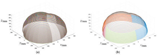
Figure 10.
(a) Workspace of the prismatic motion pattern; (b) workspace of the pyramidal motion pattern.
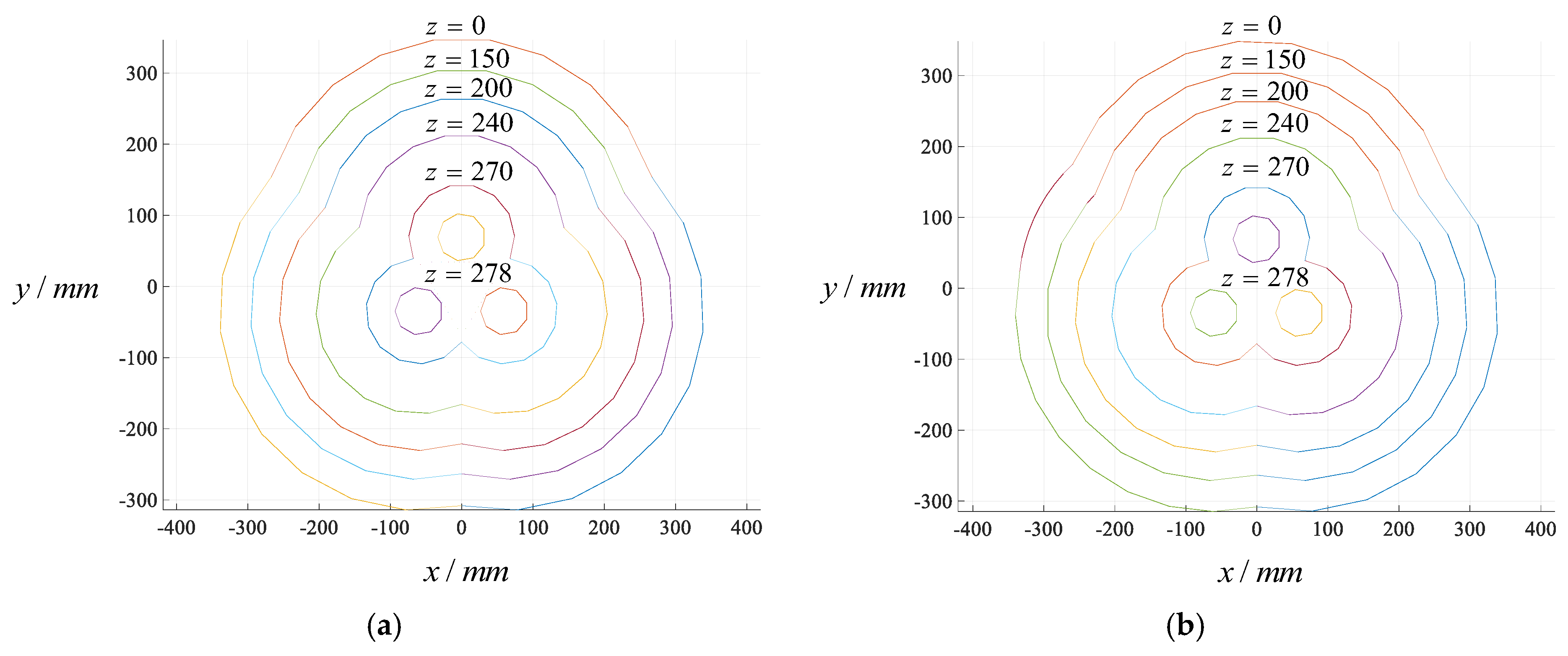
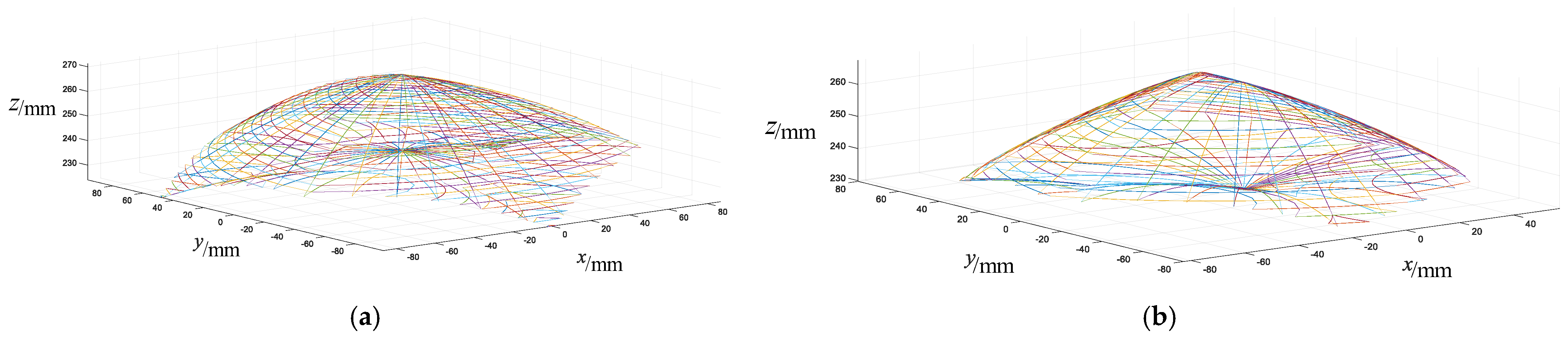
Figure 10a presents the workspace of the prismatic motion pattern of the cable-driven mobile robot, and Figure 10b illustrates the workspace of the pyramidal motion pattern of the robot. The details of the two motion patterns can be referred to in our previous work [46]. In the prismatic pattern, the robot can operate in either a large platform configuration or a small one. When the sliders in four platforms are all attracted by the outer electromagnets, the robot is in the large platform configuration, suitable for an open environment. Conversely, the robot adopts the small platform configuration when the sliders in four platforms are all attracted by the inner electromagnets, which is suitable for a narrow environment. In the prismatic pattern, the robot exhibits three distinct movement capabilities of peristalsis, crossing gaps, and translation. These motions enable the robot to adapt to various terrains and operational requirements effectively. In the pyramidal motion pattern, the sliders in platforms A and C are attracted by the outer electromagnets, and the sliders in platforms B and D are attracted by the inner electromagnets. The robot exhibits three distinct movement capabilities of head rotation, roll and vertical climbing. In the prismatic motion pattern, the length of three drive cables is limited from 240 mm to 280 mm, the length of three constraint cables is limited to 240 mm, and the length of piston rod ranges from 240 mm to 280 mm. Sections of the workspace of the two motion patterns for different values of z in a plane parallel to the xy plane are illustrated in Figure 11. It is explicit that the workspaces of two motion patterns are largest at z = 0 mm and smallest at z = 278 mm. However, the shapes of the boundary of workspace remain unchanged as z gradually increases, and the arcs no longer intersect when z = 278 mm. According to the result obtained in MATLAB R2021a, the workspace in the z-axis direction from 0 mm to 278 mm can be obtained by this robot, and area of the planar region reaches a maximum value of 352,557.7888 mm2 when z = 0 mm, reaches a minimum value of 10,518.0522 mm2 when z = 278 mm. In the pyramidal motion pattern, the cable length constraints are the same as for the prismatic motion pattern. Workspace in z-axis direction from 0 mm to 278 mm can be obtained by this robot, and area of the planar region reaches a maximum value of 325,714.4087 mm2 when z = 0 mm, reaches a minimum value of 10,518.0522 mm2 when z = 278 mm. If the three constraint cables of the robot are replaced by drive cables, then the workspace of the cable-driven mobile robot with no constraint cables can be obtained, which is illustrated in Figure 12. It is noted that the workspace in the z-axis direction can be obtained only from 224 mm to 270 mm in the prismatic motion pattern, with the maximum area of the planar region being 21,200.2824 mm2 when z = 240 mm and the minimum being 15.8188 mm2 when z = 224 mm. A reduction of the workspace in the z-axis direction also occurs in the pyramidal motion pattern, which can be obtained only from 230 mm to 266 mm. The maximum area of the planar region is 14,859.7784 mm2 when z = 240 mm, and the minimum is 2.7568 mm2 when z = 230 mm.
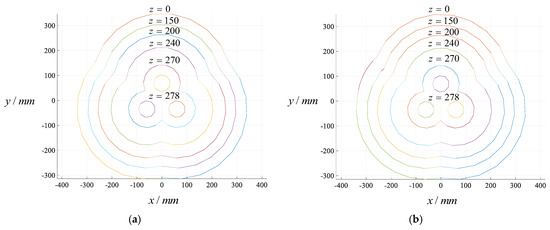
Figure 11.
(a) Sections of the workspace of the prismatic motion pattern in the plane parallel to the xy plane; (b) sections of the workspace of the pyramidal motion pattern in the plane parallel to the xy plane.
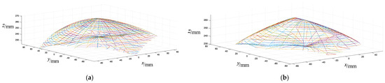
Figure 12.
(a) Workspace of the prismatic motion pattern with no constraint cables; (b) workspace of the pyramidal motion pattern with no constraint cables.
The comparison of Figure 10 and Figure 12 demonstrates that the workspace of the robot with constraint cables is different from the robot workspace with no constraint cables. This result presents the influence of constraint cables on the workspace, even within the context of a purely geometric analysis.
4. Discussions and Conclusions
The arc intersection method based on the geometric description of the boundaries of the workspace is applied to determine the workspace of a multi-pattern cable-driven hybrid mobile robot, and the dynamic model of the robot is presented, leading to the following conclusions.
- (1)
- The process of the intersection of circles and circular rings in 2D and the corresponding algorithms are reviewed briefly. Then, the arc intersection method based on these algorithms is presented to determine robot workspace. This approach ensures that the workspace analysis accounts for both the constraints imposed by the cables and the geometric limitations introduced by the piston rod. While previous studies on 6-SPS hexapods have focused on cable-driven mechanisms without considering the central piston rod, our work extends the analysis by explicitly incorporating this critical component. This integration allows for a more comprehensive understanding of the robot’s workspace under realistic operational constraints.
- (2)
- The workspaces of different motion patterns of the cable-driven mobile robot are determined, and the maximum and minimum areas of the planar region are obtained. The prismatic and pyramidal motion patterns exhibit workspaces that are largest at z = 0 mm and smallest at z = 278 mm, with the shape of the workspace boundaries remaining unchanged as z increases. The arcs no longer intersect at z = 278 mm. For the prismatic motion pattern, the robot’s workspace spans along the z-axis from 0 mm to 278 mm, achieving a maximum planar area of 352,557.7888 mm2 at z = 0 mm and a minimum of 10,518.0522 mm2 at z = 278 mm. Similarly, the pyramidal motion pattern spans the same z-axis range, with a maximum planar area of 325,714.4087 mm2 at z = 0 mm and the same minimum area at z = 278 mm. The workspaces of the cable-driven robot with no constraint cables are presented to illustrate the function of constraint cables on robot workspaces. It is observed that in the prismatic motion pattern, the workspace along the z-axis is restricted to the range of 224 mm to 270 mm. Within this range, the maximum planar area of the workspace reaches 21,200.2824 mm2 at z = 240 mm, while the minimum area is 15.8188 mm2 at z = 224 mm. Similarly, in the pyramidal motion pattern, the workspace along the z-axis is limited to the range of 230 mm to 266 mm. The maximum planar area for this pattern is 14,859.7784 mm2 at z = 240 mm, with the minimum area being 2.7568 mm2 at z = 230 mm.
- (3)
- The dynamic model of the cable-driven mobile robot is formulated, laying the foundation for the following trajectory planning. Indeed, this dynamic model is designed to aid in trajectory planning for the robot. If natural free-motion trajectories can be identified for the dynamic model, it guarantees that these trajectories can be executed by the robot while maintaining cable tension, provided that the actuator’s torque and velocity limits are respected.
The workspaces presented in this paper are obtained geometrically, which are larger than the wrench-feasible workspace, although they encompass most of it. This is a limitation of our current approach, although it provides guidance and establishes the foundation for determining the wrench-feasible workspace. To address this limitation, we will focus on solving for the wrench-feasible workspace of this robot in our future work. The expression of cable tension formulated in the dynamic model provides a deep insight into the wrench-feasible workspace. The dynamic model of the robot is necessary for the trajectory planning of the robot. The preliminary dynamic model established in this paper aims at aiding trajectory planning for the robot. While the current model provides a foundation for understanding the robot’s dynamic behavior, we acknowledge that it is a preliminary step, and further research is needed to refine and expand its capabilities. In future work, we plan to conduct deeper studies on the dynamic model, incorporating additional factors such as energy optimization, disturbance rejection, and robust control strategies to enhance its practicality and applicability.
Author Contributions
Conceptualization, J.S. and S.Y.; methodology, J.S.; software, J.W.; validation, J.S., Q.L. and M.W.; writing—original draft preparation, J.S. and S.Y.; writing—review and editing, S.Y.; visualization, M.W.; supervision, S.Y.; project administration, S.Y. All authors have read and agreed to the published version of the manuscript.
Funding
This research work is supported by the National Natural Science Foundation of China (NSFC) (Grant No. 52305042).
Data Availability Statement
The data presented in this study are available on request from the corresponding author.
Conflicts of Interest
The authors declare no conflicts of interest. The funders had no role in the design of the study; in the collection, analysis, or interpretation of the data; in the writing of the manuscript; or in the decision to publish the results.
Symbols and Abbreviations
The following symbols and abbreviations are used in this manuscript:
| R: O-xyz | The fixed coordinate frame attached to the fixed platform |
| R’: O’-x’y’z’ | The moving coordinate frame attached to the moving platform |
| Ai | The point of the fixed platform A from which cable i extends |
| Bi | The point of the moving platform B where cable i is attached |
| The position vectors of the joints on the base | |
| The position vectors of the joints on the moving platform | |
| Q | The position matrix of the moving platform relative to the base at the initial position |
| The position vector of the moving platform center O’ expressed in the fixed coordinate frame R | |
| is its length | |
| The force provided by the piston rod | |
| The vector of gravitational acceleration | |
| The tension in the ith cable | |
| I | The inertial tensor of the platform around O’ with respect to the moving frame R’ |
| The cable tension-to-length radio |
References
- Albus, J.; Bostelman, R.; Dagalakis, N. The NIST robocrane. J. Robot. Syst. 1993, 10, 709–724. [Google Scholar] [CrossRef]
- Cone, L.L. Skycam: An aerial robotic camera system. Byte 1985, 10, 122–132. [Google Scholar]
- Pott, A. Cable-Driven Parallel Robots: Theory and Application; Springer: Cham, Switzerland, 2018. [Google Scholar]
- Duan, B. A new design project of the line feed structure for large spherical radio telescope and its nonlinear dynamic analysis. Mechatronics 1999, 9, 53–64. [Google Scholar] [CrossRef]
- Zi, B.; Duan, B.; Du, J.; Bao, H. Dynamic modeling and active control of a cable-suspended parallel robot. Mechatronics 2008, 18, 1–12. [Google Scholar] [CrossRef]
- Zi, B.; Qian, S. Design, Analysis and Control of Cable-Suspended Parallel Robots and Its Applications; Springer: Singapore, 2017. [Google Scholar]
- Koh, J.S.; Cho, K.J. Omega-shaped inchworm-inspired crawling robot with large-index-and-pitch (LIP) SMA spring actuators. IEEE/ASME Trans. Mechatron. 2013, 18, 419–429. [Google Scholar] [CrossRef]
- Wang, D.; Dai, J.S. Theoretical foundation of metamorphic Mechanisms and their synthesis. Chin. J. Mech. Eng. 2007, 43, 32–42. [Google Scholar] [CrossRef]
- Wang, R.; Song, Y.; Dai, J.S. Reconfigurability of the origami-inspired integrated 8R kinematotropic metamorphic mechanism and its evolved 6R and 4R mechanisms. Mech. Mach. Theory 2021, 161, 104245. [Google Scholar] [CrossRef]
- Li, P.; Han, H.; Liu, C.; Ren, B.; Wu, Q.; Xu, Z. Workspace analysis of axial offset joint based on parameterization. Robotica 2023, 41, 2882–2906. [Google Scholar] [CrossRef]
- Bibekananda, P.; Anirban, N.; Sandipan, B. Analytical determination of the optimal effective regular workspace of a 6-6 Stewart platform manipulator for a specified orientation workspace. Mech. Mach. Theory 2024, 203, 105791. [Google Scholar] [CrossRef]
- Kolte, A.M.; Ramesh, S.; Bandyopadhyay, S. Analytical derivation of singularity-free tubes in the constant-orientation workspace of 6-6 Stewart platform manipulators. Robotica 2024, 42, 3839–3866. [Google Scholar] [CrossRef]
- Andrea, M.P.; Sergio, J.P.; Antonio, G.R.; Angel Gaspar, G.R.; Alfonso Isidro, L.D.; Guillermo, R.G. A novel design for fully constrained planar Cable-Driven Parallel Robots to increase their wrench-feasible workspace. Mech. Mach. Theory 2023, 180, 105159. [Google Scholar]
- Zhao, X.; Zhao, Z.; Liu, Y.; Su, C.; Meng, J. Analysis of workspace boundary for multi-robot coordinated lifting system with rolling base. Robotica 2024, 42, 3657–3674. [Google Scholar] [CrossRef]
- Edoardo, I.; Marco, C. Static workspace computation for underactuated cable-driven parallel robots. Mech. Mach. Theory 2024, 193, 105551. [Google Scholar]
- Qian, S.; Zhao, Z.; Qian, P.; Wang, Z.; Zi, B. Research on workspace visual-based continuous switching sliding mode control for cable-driven parallel robots. Robotica 2024, 42, 1–20. [Google Scholar] [CrossRef]
- Salemo, M.; Zhang, K.; Menciassi, A.; Dai, J.S. A novel 4-DOFs origami enabled, SMA actuated, robotic end-effector for minimally invasive surgery. In Proceedings of the 2014 IEEE International Conference on Robotics and Automation (ICRA), Hong Kong, China, 31 May–5 June 2014. [Google Scholar]
- Qin, Y.; Dai, J.S.; Gogu, G. Multi-furcation in a derivative queer-square mechanism. Mech. Mach. Theory 2014, 81, 36–53. [Google Scholar] [CrossRef]
- Yao, L.; Gu, B.; Haung, S.; Wei, G.; Dai, J.S. Mathematical modeling and simulation of the external and internal double circular-arc spiral bevel gears for the nutation drive. ASME J. Mech. Des. 2010, 132, 021008. [Google Scholar] [CrossRef]
- Huo, X.; Song, Z.; Sun, T. A machine learning-based approach for automatic motion/constraint and mobility analysis of parallel robots. Robotica 2024, 42, 2403–2429. [Google Scholar] [CrossRef]
- Gao, C.; Kang, X.; Lei, H.; Xu, P.; Li, B. Design and analysis of a novel large-span two-fold deployable mechanism. Mech. Mach. Theory 2023, 186, 105352. [Google Scholar] [CrossRef]
- Zhang, X.; Kang, X.; Li, B. Origami-inspired design of a single-degree-of-freedom reconfigurable wing with lockable mechanisms. ASME J. Mech. Robot. 2024, 16, 071008. [Google Scholar] [CrossRef]
- Gouttefarde, M.; Daney, D.; Merlet, J.P. Interval-analysis-based determination of the wrench-feasible workspace of parallel cable-driven robots. IEEE Trans. Robot. 2011, 27, 1–13. [Google Scholar] [CrossRef]
- Jaulin, L.; Kieffer, M.; Didrit, O.; Walter, E. Applied Interval Analysis; Springer: London, UK, 2001. [Google Scholar]
- Neumaier, A. Interval Methods for Systems of Equations; Cambridge University Press: Cambridge, UK, 1990. [Google Scholar]
- Gosselin, C. Determination of the workspace of 6-DOF parallel manipulators. ASME J. Mech. Des. 1990, 112, 331–336. [Google Scholar] [CrossRef]
- Gosselin, C.; Angeles, J. The optimum kinematic design of a spherical three-degree-of-freedom parallel manipulator. ASME J. Mech. Trans. Autom. 1989, 111, 202–207. [Google Scholar] [CrossRef]
- Spyrakos-Papastavidis, E.; Dai, J.S. Minimally model-based trajectory tracking and variable impedance control of flexible-joint robots. IEEE Trans. Ind. Electron. 2020, 68, 6031–6041. [Google Scholar] [CrossRef]
- Dai, J.S.; Zoppi, M.; Kong, X. Advances in Reconfigurable Mechanisms and Robots I; Springer: London, UK, 2012. [Google Scholar]
- Kang, X.; Lin, Q.; Feng, H.; Li, B. Double-level reconfigurable variation of Bennett-induced 8R mechanism and its evolved metamorphic 7R mechanism family. Mech. Mach. Theory 2025, 205, 105879. [Google Scholar] [CrossRef]
- Zhang, X.; Kang, X.; Li, B. Development and investigation for rigid-flexible coupling dynamic performances of the morphing wing with clearance joints. Mech. Syst. Signal Process. 2025, 223, 111871. [Google Scholar] [CrossRef]
- Zhang, Y.; Wang, W.; Kang, X.; Li, B. Design, analysis, and experimentation of deployable multi-closed-loop truss modules for aerospace platforms. Mech. Mach. Theory 2025, 205, 105897. [Google Scholar] [CrossRef]
- Zhang, Y.; Kang, X.; Li, B. A family of folding single-loop metamorphic mechanisms for aerospace manipulators: Synthesis, network, and analysis. Mech. Mach. Theory 2024, 201, 105728. [Google Scholar] [CrossRef]
- Wang, S.; Huang, H.; Jia, G.; Li, B.; Guo, H.; Liu, R. Design of a novel three-limb deployable mechanism with mobility bifurcation. Mech. Mach. Theory 2022, 172, 104789. [Google Scholar] [CrossRef]
- Jia, G.; Huang, H.; Wang, S.; Li, B. Type synthesis of plane-symmetric deployable grasping parallel mechanisms using constraint force parallelogram law. Mech. Mach. Theory 2021, 161, 104330. [Google Scholar] [CrossRef]
- Jia, G.; Li, B.; Huang, H.; Zhang, D. Type synthesis of metamorphic mechanisms with scissor-like linkage based on different kinds of connecting pairs. Mech. Mach. Theory 2020, 151, 103848. [Google Scholar] [CrossRef]
- Feng, H.; Peng, R.; Zang, S.; Ma, J.; Chen, Y. Rigid foldability and mountain-valley crease assignments of square-twist origami pattern. Mech. Mach. Theory 2020, 152, 103947. [Google Scholar] [CrossRef]
- Ma, J.; Zang, S.; Feng, H.; Chen, Y.; You, Z. Theoretical characterization of a non-rigid-foldable square-twist origami for property programmability. Int. J. Mech. Sci. 2021, 189, 105981. [Google Scholar] [CrossRef]
- Ye, S.; Zhao, P.; Zhao, Y.; Kavousi, F.; Feng, H.; Hao, G. A novel radially closable tubular origami structure (RC-ori) for valves. Actuators 2022, 11, 243. [Google Scholar] [CrossRef]
- Huo, X.; Lian, B.; Wang, P.; Song, Y.; Sun, T. Dynamic identification of a tracking parallel mechanism. Mech. Mach. Theory 2020, 155, 104091. [Google Scholar] [CrossRef]
- Huo, X.; Sun, T.; Song, Y. Geometric algebra approach to determine motion/constraint, mobility and dingularity of parallel mechanism. Mech. Mach. Theory 2017, 116, 273–293. [Google Scholar] [CrossRef]
- Song, Y.; Kang, X.; Dai, J.S. Instantaneous mobility analysis using the twist space intersection approach for parallel mechanisms. Mech. Mach. Theory 2020, 151, 103866. [Google Scholar] [CrossRef]
- Qi, J.; Zhang, J.; Yang, F.; Song, Y. Kinematic modeling of 3D clearance in revolute joint and its application in overconstrained linkages. In Proceedings of the Advances in Mechanism, Machine Science and Engineering in China, Yantai, China, 30 July–1 August 2022. [Google Scholar]
- Chen, Z.; An, K.; Wang, Z.; Miao, T.; Song, Y.; Shangguan, Q. Dynamic optimization of mechanism parameters of bipedal robot considering full-range walking energy efficiency. Appl. Sci. 2023, 13, 10791. [Google Scholar] [CrossRef]
- Song, J.; Yang, S.; Zhang, Y.; Fang, Z.; Zou, T. Type synthesis of closed-loop robots for machining and manufacturing of complex quadric surfaces. Robotica 2025, 1–29. [Google Scholar] [CrossRef]
- Song, J.; Zou, T.; Liu, Q.; Wu, J.; Yang, S.; Zhang, Y. The conceptual design of multi-pattern cable-driven hybrid robot. In Proceedings of the 2025 International Conference on Mechanical Design (ICMD), Hangzhou, China, 9–11 May 2025; in press. [Google Scholar]
- Xue, F.; Fang, Z.; Song, J.; Liu, Q.; Yang, S. A new method for displacement modelling of serial robots using finite screw. Machines 2024, 12, 658. [Google Scholar] [CrossRef]


Disclaimer/Publisher’s Note: The statements, opinions and data contained in all publications are solely those of the individual author(s) and contributor(s) and not of MDPI and/or the editor(s). MDPI and/or the editor(s) disclaim responsibility for any injury to people or property resulting from any ideas, methods, instructions or products referred to in the content. |
© 2025 by the authors. Licensee MDPI, Basel, Switzerland. This article is an open access article distributed under the terms and conditions of the Creative Commons Attribution (CC BY) license (https://creativecommons.org/licenses/by/4.0/).