Article

Motion Sickness Suppression Strategy Based on Dynamic Coordination Control of Active Suspension and ACC

Henan Provincial Key Laboratory of Intelligent Manufacturing of Mechanical Equipment, Zhengzhou University of Light Industry, Zhengzhou 450002, China
*
Author to whom correspondence should be addressed.
Machines 2025, 13(8), 650; https://doi.org/10.3390/machines13080650
Submission received: 10 June 2025 / Revised: 10 July 2025 / Accepted: 22 July 2025 / Published: 24 July 2025
(This article belongs to the Section Vehicle Engineering)

Abstract

With the development of electrification and intelligent technologies in vehicles, ride comfort issues represented by motion sickness have become a key constraint on the performance of autonomous driving. The occurrence of motion sickness is influenced by the comprehensive movement of the vehicle in the longitudinal, lateral, and vertical directions, involving ACC, LKA, active suspension, etc. Existing motion sickness control method focuses on optimizing the longitudinal, lateral, and vertical directions separately, or coordinating the optimization control of the longitudinal and lateral directions, while there is relatively little research on the coupling effect and coupled optimization of the longitudinal and vertical directions. This study proposes a coupled framework of ACC and active suspension control system based on MPC. By adding pitch angle changes caused by longitudinal acceleration to the suspension model, a coupled state equation of half-car vertical dynamics and ACC longitudinal dynamics is constructed to achieve integrated optimization of ACC and suspension for motion suppression. The suspension active forces and vehicle acceleration are regulated coordinately to optimize vehicle vertical, longitudinal, and pitch dynamics simultaneously. Simulation experiments show that compared to decoupled control of ACC and suspension, the integrated control framework can be more effective. The research results confirm that the dynamic coordination between the suspension and ACC system can effectively suppress the motion sickness, providing a new idea for solving the comfort conflict in the human vehicle environment coupling system.

1. Introduction

Motion sickness is a physiological functional disorder syndrome that occurs in specific motion environments, characterized by typical symptoms such as motion sickness, nausea, vomiting, and cold sweats. Its underlying mechanism stems from neural compensatory imbalance triggered by perceptual conflicts among the vestibular, visual, and proprioceptive systems [1]. With the accelerated transformation of the automotive industry toward the “new four modernizations”, L2 and above-intelligent EVs have become core components of urban intelligent transportation systems [2]. However, this shift has been accompanied by a significant increase in the incidence of in-vehicle motion sickness, which compromises the comfort of transportation experiences [3].
From the perspective of vehicle dynamics, the longitudinal and vertical dynamic characteristics of EVs are key factors aggravating motion sickness. The high torque and rapid response of electric motors, combined with electro-mechanical braking, result in nonlinear fluctuations during acceleration/deceleration, suspension vibrations induced by road excitation reduce ride comfort, the coupling effect between suspension vibrations and longitudinal dynamic induces pitch motion, significantly increasing motion sickness risk [4]. Autonomous driving tends to cause sensory conflict between visual and vestibular systems, thereby increasing the likelihood of motion sickness occurrence [5].
Thus, against the backdrop of electrification and intelligentization, motion sickness-related ride comfort has emerged as a critical issue that cannot be overlooked. There is an urgent need to incorporate motion sickness mitigation metrics into vehicle control systems. Current research on motion sickness in intelligent EVs primarily focuses on two aspects: motion sickness prediction and motion sickness suppression control. Research on motion sickness prediction can be further divided into intrinsic physiological mechanisms of motion sickness and the correlation between vehicle motion parameters and motion sickness incidence.
In the study of intrinsic physiological mechanisms of motion sickness, Keshavarz et al. [6] systematically summarized the physiological mechanisms of neural compensatory imbalance, while Laessoe et al. [7] and Ng et al. [8] demonstrated the regulatory effect of visuo-vestibular synchronization on symptoms. Gruden et al. [9] further validated through EGG that such conflicts directly translate into quantifiable physiological signals. Studies also identified significant individual variability in susceptibility, with motion sickness-prone individuals exhibiting higher sensitivity to perceptual mismatches [10,11].
In the study of the relationship between vehicle motion parameters and motion sickness, longitudinal, lateral, and vertical accelerations are found to significantly correlate with motion sickness [12]. Zhao et al. [13] established a prediction model using vehicle accelerations through driving tests, and Tian et al. [14] further added trip duration and individual variability in the model to improve prediction accuracy. Iskander et al. [15] specifically investigated non-driving-related activities in autonomous vehicles, developing a predictive framework for such scenarios. Kia et al. [16] experimentally verified that active suspension seats could reduce WBV and corresponding motion sickness. Jin et al. [17] demonstrate that semi-active suspension can effectively alleviate motion sickness by suppressing vertical acceleration and pitch angular velocity.
Based on the foregoing analysis, motion sickness primarily stems from two physiological mechanisms: sensory conflict between visual and vestibular inputs and the impact of vehicle motion states. Critical vehicle-induced motion sickness parameters include vertical acceleration at the center of mass, pitch angular velocity, and longitudinal acceleration, all of which demonstrate strong correlations with motion sickness incidence.
In the field of motion sickness suppression control, researchers have achieved preliminary results in both vehicle dynamics optimization and intelligent motion planning algorithms.
Cui et al. [18] proposed an adaptive wheelbase preview robust H control method that can accurately identify road roughness information and suppress vehicle body vibration. It not only satisfies driving smoothness but also takes into account passenger driving experience. Chen et al. [19] proposed an intelligent chassis-coordinated control algorithm that combines wheel ground tangential force control that effectively improves the vertical vibration acceleration level of the body, reduces the incidence rate of motion sickness, and improves the driving comfort and other comprehensive performance of intelligent chassis vehicles. Feng et al. [20] proposes a model predictive control-based integrated torque vectoring and active suspension strategy, optimizing longitudinal and vertical dynamics via a linear time-varying half-vehicle model, effectively enhancing energy efficiency and ride comfort of four-wheel independently driven electric vehicles while ensuring stability. Liang et al. [21] proposed a decentralized cooperative control framework of AFS and ASS by applying MDMPC, effectively enhancing the vehicle lateral and vertical stability during path tracking. Zheng et al. [22] propose a nonlinear model predictive control method for curve tilt function for active suspension in vehicle lateral motion to counteract inertial lateral acceleration. The lateral acceleration is significantly reduced to suppress the occurrence of motion sickness. Winkel et al. [23] demonstrate that discomfort increases with acceleration and jerk and propose a motion comfort prediction model.
In motion planning, researchers have developed various comfort-oriented trajectory planning methods. Htike et al. [24] and Geng et al. [25] achieved a balance among motion sickness reduction, driving safety, and driving efficiency through multi-objective optimization. Li et al. [26] developed a motion-planning algorithm incorporating frequency-shaping techniques and significantly reduced MSDV compared to conventional methods. Rajesh et al. [27] applied DRL to autonomous vehicle trajectory planning to minimize low-frequency accelerations and thereby suppress motion sickness symptoms. Additionally, Gysen et al. [28] and Papaioannou et al. [29] investigated the structure and performance of active suspension systems, demonstrating their effectiveness in mitigating motion sickness.
Although the aforementioned studies have achieved significant progress in vehicle dynamics control and intelligent motion planning, most results have focused on longitudinal–lateral cooperative control and steady-state lateral–vertical control during steering maneuvers. Research on the coupling mechanisms and cooperative control of vertical–longitudinal excitations, which significantly influence motion sickness, remains insufficient. The longitudinal acceleration changes generated by ACC systems during car-following or speed adjustments can aggravate vehicle pitch motion, acting on the front and rear suspensions. Traditional suspension control primarily targets the suppression of road-induced vibrations transmitted through tires, often lacking coordinated optimization for ACC-induced pitch motion or merely treating speed/acceleration as disturbances to the controller, resulting in suboptimal performance. Moreover, current ACC algorithms mainly focus on safety and fuel efficiency, paying less attention to the impact of acceleration/deceleration profiles on passenger comfort. Meanwhile, suspension control often overlooks the interference of longitudinal vehicle motion on body posture. Such fragmented control strategies make it difficult to fundamentally address motion sickness. Therefore, the coordinated control of ACC and suspension systems is crucial for motion sickness suppression. By integrating ACC acceleration planning with active suspension control and incorporating both suspension control forces and longitudinal vehicle acceleration as control variables, it is possible to optimize body pitch and vertical vibration characteristics during acceleration/braking. This approach enables coordinated longitudinal–vertical dynamics coupling control, effectively suppressing the occurrence of motion sickness.
Based on the above analysis, this study focuses on motion sickness suppression control technologies for autonomous vehicles. The main approach involves coupled modeling and control of active suspension and ACC to coordinately regulate longitudinal and vertical dynamics and suppress motion sickness. The paper is structured as follows: Section 2 presents coupled dynamic modeling of the suspension and ACC systems along with control system design; Section 3 provides simulation verification; and Section 4 offers conclusions and future perspectives.

2. Materials and Methods

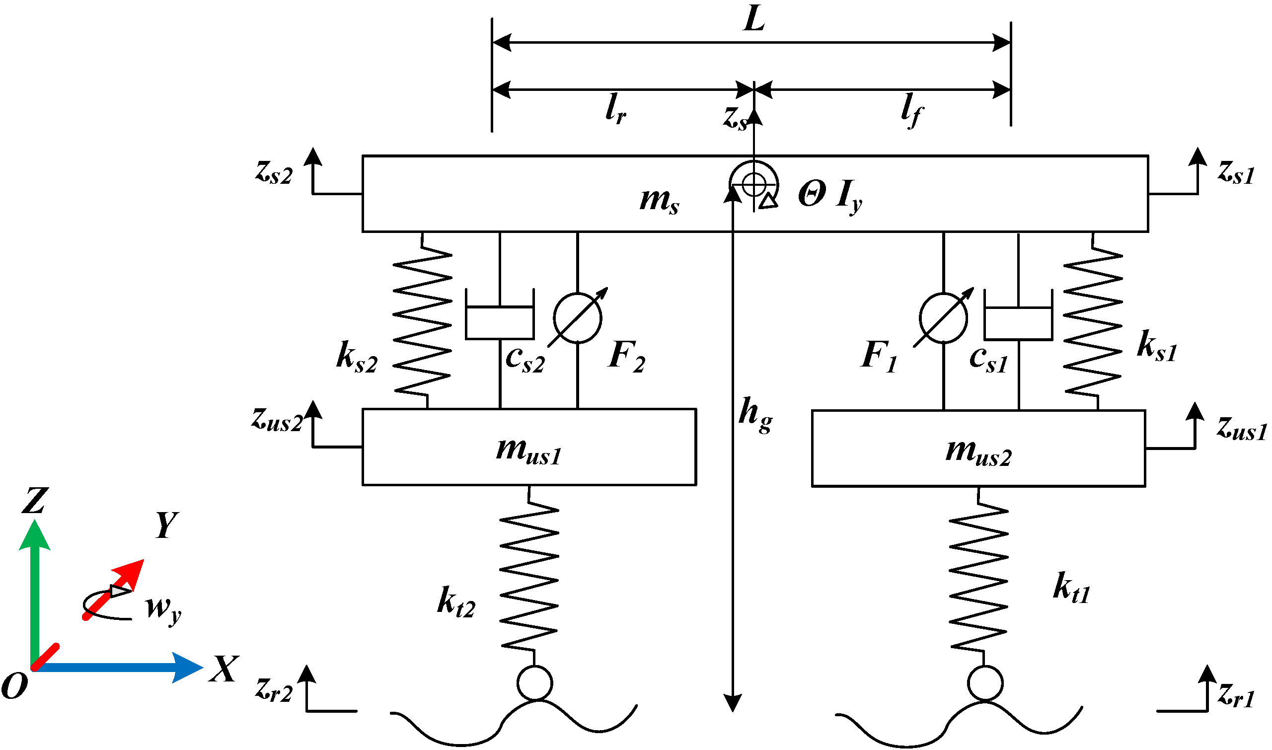
2.1. Vertical Dynamics

In this study, the vehicle’s pitch motion induced by front and rear suspension interactions is identified as one of the contributing factors to motion sickness. Half-car suspension model is introduced to characterize this feature. This model integrates two quarter-car suspensions; model construction is shown in Figure 1.
In Figure 1, ms is the sprung mass, mus1 and mus2 represent the unsprung masses of the front and rear suspensions, respectively, Fs1 and Fs2 represent the spring forces of the front and rear suspensions, ks1 and ks2 represent the spring stiffnesses of the front and rear suspensions, Fd1 and Fd2 represent the damping forces of the front and rear suspensions, cs1 and cs2 represent their respective damping coefficients, F1 and F2 represent the active control forces of the front and rear suspensions, Ft1 and Ft2 represent the elastic forces generated by the front and rear tires, kt1 and kt2 represent the equivalent spring stiffnesses of the front and rear tires, zs represents the vertical displacement of the sprung mass center, zs1 and zs2 represent the vertical displacements at the connection points between the sprung mass and the front/rear suspensions, zus1 and zus2 represent the vertical displacements of the front and rear unsprung mass centers, zr1 and zr2 represent the vertical road excitations acting on the front and rear tires, Iy represents the moment of inertia of the sprung mass about the Y-axis, and θ represents the pitch angle. The combined action of the front and rear suspensions induces variations in the pitch angle, with displacements and forces defined as positive in the upward direction.
Based on the vertical force balance analysis, the vertical dynamics equation of the sprung mass ms is:
m s z ¨ s = F s 1 + F d 1 + F s 2 + F d 2 + F 1 + F 2
In which:
F s 1 = k s 1 ( z s 1 z u s 1 )
F d 1 = c s 1 ( z ˙ s 1 z ˙ u s 1 )
F s 2 = k s 2 ( z s 2 z u s 2 )
F d 2 = c s 2 ( z ˙ s 2 z ˙ u s 2 )
Based on the geometric kinematics of the sprung mass pitching:
z s 1 = z s l f s i n θ
z s 2 = z s + l r s i n θ
Based on the moment balance analysis about the Y-axis, the pitch dynamics equation of the sprung mass ms is:
I y θ ¨ s = l f ( F s 1 + F d 1 + F 1 ) + l r ( F s 2 + F d 21 + F 2 )
The vertical dynamics equation for the front unsprung mass mus1 is derived as:
m u s 1 z ¨ s 1 = F s 1 F d 1 F 1 + F t 1
F t 1 = k t 1 ( z u s 1 z u r 1 )
The vertical dynamics equation for the rear unsprung mass mus2 is derived as:
m u s 2 z ¨ s 2 = F s 2 F d 2 F 2 + F t 2
F t 2 = k t 2 ( z u s 2 z u r 2 )
Furthermore, since vehicle acceleration/deceleration induces pitch motion and affects front/rear suspension dynamics, the disturbance input from longitudinal acceleration aego is incorporated into the half-car suspension model. During acceleration/deceleration, ground reaction forces generate a pitch moment about the Y-axis at the center of mass. This moment is added to the equations to characterize the coupling effect of aego on suspension dynamics. Consequently, Equation (8) is modified as:
I y θ ¨ s = l f ( F s 1 + F d 1 + F 1 ) + l r ( F s 2 + F d 21 + F 2 ) m s a e g o h g
In which, aego represents ego car acceleration, hg is sprung mass center of gravity height.
Based on the above analysis, a control-oriented model for the half-car suspension system is constructed as follows:
  • Model Control Variables: U s u s = [ F 1 , F 2 ] T
  • Model Disturbance Inputs: U d s u s = [ z r 1 , z r 2 , a e g e ] T
  • Model State Variables: X s u s = [ z s , θ , z u s 1 , z u s 2 , z ˙ s , θ ˙ , z ˙ u s 1 , z ˙ u s 2 ]
  • Model Output Variables: Y s u s = [ z ˙ s , θ , z s 1 z u s 1 , z s 2 z u s 2 ]
System model is
X ˙ s u s = A s u s X s u s + B s u s U s u s + B d s u s U d s u s Y s u s = C s u s X s u s
Based on the model above, system matrix Asus, Bsus, Bdsus, and Csus are represented as:
A s u s = 0 0 0 0 1 0 0 0 0 0 0 0 0 1 0 0 0 0 0 0 0 0 1 0 0 0 0 0 0 0 0 1 k s 1 + k s 2 m s k s 1 l f k s 2 l r m s k s 1 m s k s 12 m s c s 1 + c s 2 m s c s 1 l f c s 2 l r m s c s 1 m s c s 2 m s k s 1 l f k s 2 l r I y k s 1 l f 2 + k s 2 l r 2 I y k s 1 l f I y k s 2 l r I y c s 1 l f c s 2 l r I y c s 1 l f 2 + c s 2 l r 2 I y c s 1 l f I y c s 2 l r I y k s 1 m s 1 k s 1 l f m s 1 k s 1 + k r 1 m s 1 0 c s 1 m s 1 c s 1 l f m s 1 c s 1 m s 1 0 k s 2 m s 2 k s 2 l r m s 2 0 k s 2 + k r 2 m s 2 c s 2 m s 2 c s 2 l r m s 2 0 c s 2 m s 2 8 × 8
B sus = 0 0 0 0 0 0 0 0 1 m s1 1 m s1 l f I y l r I y 1 m s1 0 0 1 m s2 8 × 2 B dsus = 0 0 0 0 0 0 0 0 0 0 0 0 0 0 0 0 0 m s h g I y k r1 m s1 0 0 0 k r2 m s2 0 8 × 3
C s u s = 0 0 0 0 1 0 0 0 0 1 0 0 0 0 0 0 1 l f 1 0 0 0 0 0 1 l r 0 1 0 0 0 0 4 × 8

2.2. ACC Control

ACC is a L2 ADAS. It calculates target acceleration and executes control based on information such as set speed, preceding vehicle speed, and relative distance. Typically, ACC is implemented using MPC. Below is a generic MPC-based ACC control methodology.
The ACC working principle is shown in Figure 2.
In Figure 2, vlead represents lead car velocity, d represents the distance between lead car and ego car, vego represents ego car velocity, and aego represents ego car acceleration. According to the vehicle motion equation, it can be concluded that:
d ˙ = v e g o + v l e a d
v ˙ e g o = a e g o
For vehicles, the execution of acceleration and deceleration signals requires passing through the actuator, introducing a time delay. Therefore, the target acceleration acmd is defined, and a first-order delay is assumed between acmd and aego:
a ˙ e g o = 1 τ ( a c m d a e g o )
In Equation (20), τ represents the actuator time constant. In this study, the EV actuator comprises the drive motor and other potential transmission mechanisms, and τ is selected as 0.2 s to represent the dynamic characteristics of them.
The control model of ACC is defined as follows:
  • Model Control Variables: U a c c = a c m d
  • Model Disturbance Inputs: U d a c c = v l e a d
  • Model State Variables: X a c c = [ d , v e g o , a e g o ] T
  • Model Output Variables: Y a c c = [ d , v e g o , a e g o ] T
According to the model above, system matrix is:
A a c c = 0 1 0 0 0 1 0 0 1 τ 3 × 3 , B a c c = 0 0 1 τ 3 × 1 , B d a c c = 1 0 0 3 × 1 C a c c = 1 0 0 0 1 0 0 0 1 3 × 3 , D a c c = [ ]

2.3. Coupled Dynamics Integration

The suspension control model described by Equations (14)–(17) is integrated with the ACC control model represented by Equation (21). During this integration process, aego transitions from an external disturbance to a controllable state variable.
  • Model Control Variables: U = [ F 1 , F 2 , a c m d ] T
  • Model Disturbance Inputs: U d = [ z r 1 , z r 2 , v l e a d ] T
  • Model State Variables: X = [ z s , θ , z u s 1 , z u s 2 , z ˙ s , θ ˙ , z ˙ u s 1 , z ˙ u s 2 , d , v e g o , a e g o ]
  • Model Output Variables: Y = [ z ˙ s , θ , z s 1 z u s 1 , z s 2 z u s 2 , d , v e g o , a e g o ]
The integrated matrix A is represented as:
A = A s u s A a c c s u s A s u s a c c A a c c 11 × 11
Matrix Aacc→sus has dimensions of 8 × 3, representing the direct influence of the 3 variables in Xacc on the 8 variables in Xsus; in Xacc = [d, vego, aego], d and vego do not have any direct effect on Xsus, so the first two columns of Aacc→sus are entirely 0; only aego exerts a direct influence on aego. As aego corresponds to the third component of the disturbance vector Bdsus in the suspension control model, its mathematical relationship with Xsus is represented by the third column of Bdsus. Therefore, the third column of Aacc→sus is identical to the third column of Bdsus, Aacc→sus = [08×2, Bdsus(:,3)].
Matrix Asus→acc has dimensions of 3 × 8, representing the direct influence of the 8 variables in Xsus on the 3 variables in Xacc. However, since Xsus does not directly affect Xacc, Asus→acc is a zero matrix.
Matrix A is represented as:
A = A s u s [ 0 8 × 2 , B d s u s ( : , 3 ) ] 0 3 × 8 A a c c 11 × 11
The integrated disturbance matrix Bdsus characterizes the direct influence of external disturbances Ud = [zr1, zr2, vlead] on state vector Xsus.
Since aego from Udsus has been converted to a state variable, its corresponding column in Bdsus has been transferred to the state matrix A. Consequently, Bdsus now retains only the first two columns, representing the direct effects of zr1 and zr2 on the system states.
Matrix Bd can be expressed as:
B d = B d s u s ( : , 1 : 2 ) 0 8 × 1 0 3 × 2 B d a c c 11 × 3
In Equation (24), 08×1 indicates that vlead does not directly disturb Xsus, while 03×2 indicates that zr1 and zr2 do not directly disturb Xacc.
Matrix B and C are integrated using a similar approach, and the final integrated system matrix is expressed as:
A = A s u s [ 0 8 × 2 , B d s u s ( : , 3 ) ] 0 3 × 8 A a c c 11 × 11 , B = B s u s 0 8 × 1 0 3 × 2 B a c c 11 × 3 , B d = B d s u s ( : , 1 : 2 ) 0 8 × 1 0 3 × 2 B d a c c 11 × 3 , C = C s u s 0 4 × 3 0 3 × 8 C a c c 7 × 11

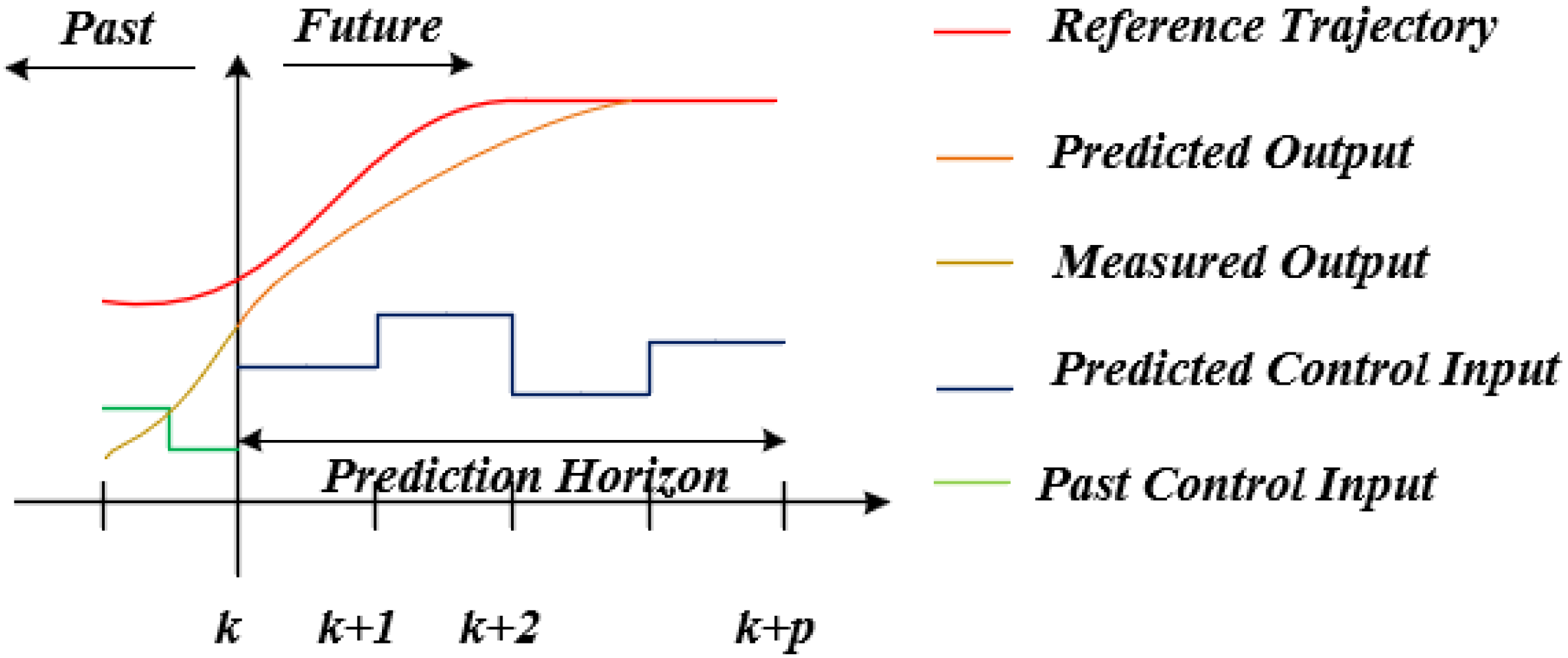
2.4. MPC-Based Integrated Controller Design

MPC is a modern control theory based on receding horizon optimization and feedback correction. Its core principle involves constructing and solving finite-horizon optimization problems online, converting the optimization into a QP problem, as is shown in Figure 3. It computes the optimal control sequence for MIMO systems and dynamically applies this sequence to achieve real-time system regulation. In the context of motion sickness mitigation, MPC can reconcile conflicting objectives between suspension vertical forces and ACC longitudinal acceleration while handling system constraints.
MPC predicts future system dynamics based on a discretized state-space model. For the integrated half-vehicle suspension and ACC coupled system, the state equation can be formulated as:
X ˙ = A X + B U + B d U d Y = C X
At each time step k, MPC generates a control sequence by solving the following optimization problem:
m i n i = 0 N p 1 ( | | y ( k + i | k ) y r e f ( k + i | k ) | | Q 2 + | | u ( k + i | k ) | | R 2 ) + ρ ε 2
After determining hyperparameters, weighting factors, and constraint parameters, the MPC algorithm transforms the control problem into a standard QP formulation as follows:
m i n 1 2 Δ U T H Δ U + f T Δ U
where Δ U = [ Δ u ( k | k ) , Δ u ( k + 1 | k ) , , Δ u ( k + N c 1 | k ) ] T represents the control increment sequence applied to the system.

3. Results

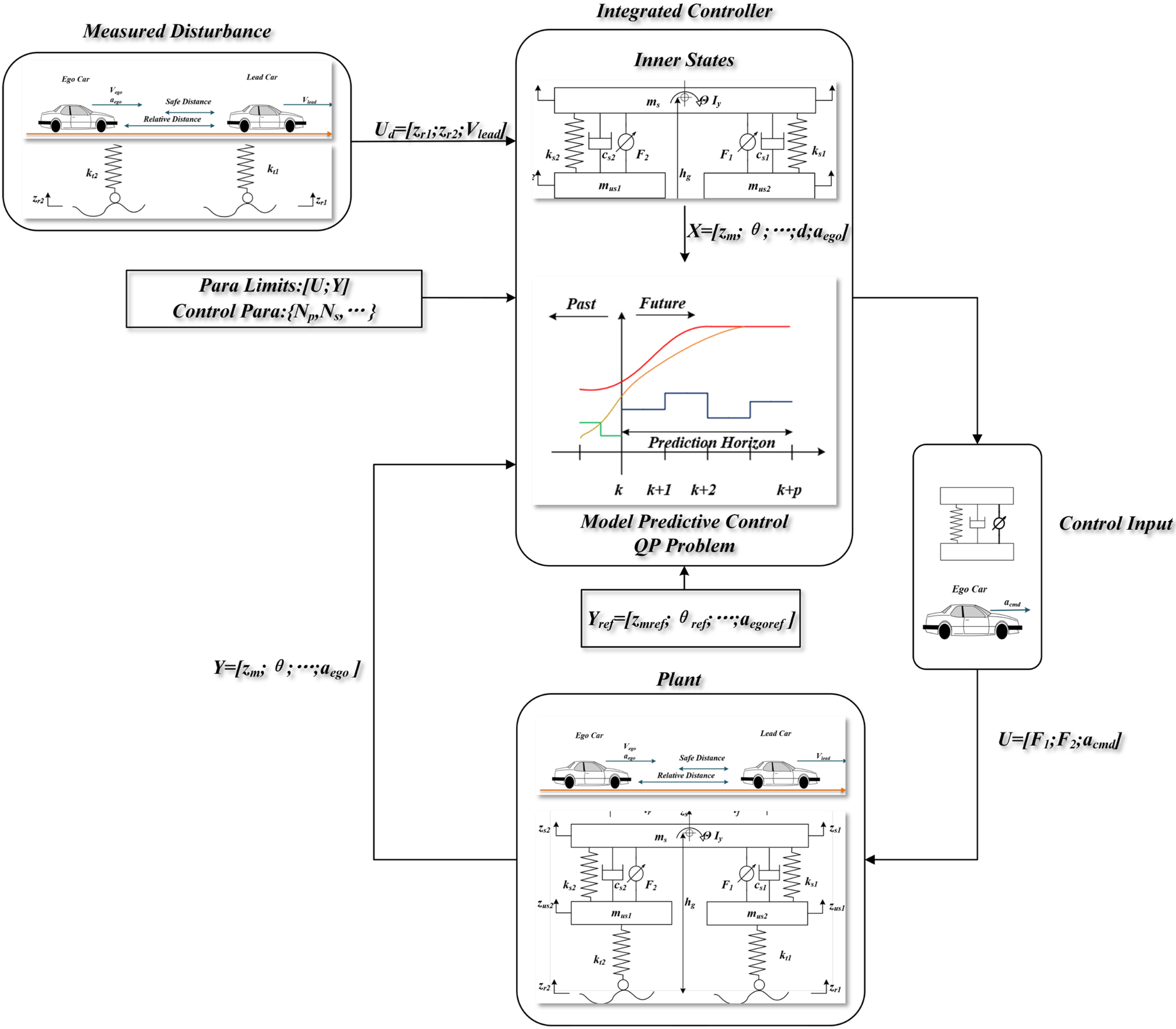
3.1. Coupled Control System Architecture

The vehicle dynamics model and MPC-based control system incorporating both vertical and longitudinal motions was developed in Matlab/Simulink (R2024b). The model consists of two main components: the plant and the control system, as illustrated in Figure 4. The control system receives measured signals Y and noise Ud from the plant, estimates system states, solves the MPC optimization problem to derive control signals U, and finally applies them to the plant for closed-loop control.
Vehicle parameters are detailed in Table 1.
The designed MPC control system hyperparameters are listed in Table 2. The discretization period was determined by integrating suspension control and ACC requirements: while ACC typically operates at around 100 ms control cycles, suspension control requires shorter cycles of 5–20 ms to respond to high-frequency road excitations. Balancing ACC/suspension control demands and system complexity, a 20 ms control period was selected.
The constructed controller is a linear MPC. According to the hyperparameter analysis in Table 2 and the control model architecture in Equation (25), the dimension of the Hessian matrix is 60 × 60, with a computational complexity of approximately O(603). It can stably run on automotive controllers and meet the real-time update requirement of 20 ms.
The control system’s input/output constraints are listed in Table 3.

3.2. System Decoupled Simulation

3.2.1. Suspension Control Simulation

Based on the half-car suspension described in Section 2.1, simulation is conducted without considering disturbances from ACC. Suspension simulation is performed on a Class B road surface, with the results shown in Figure 5. It can be observed that the vertical velocity of the sprung mass is constrained within 0.1, and the pitch angle does not exceed 0.01 rad. These results demonstrate the multi-objective coordination capability of MPC.

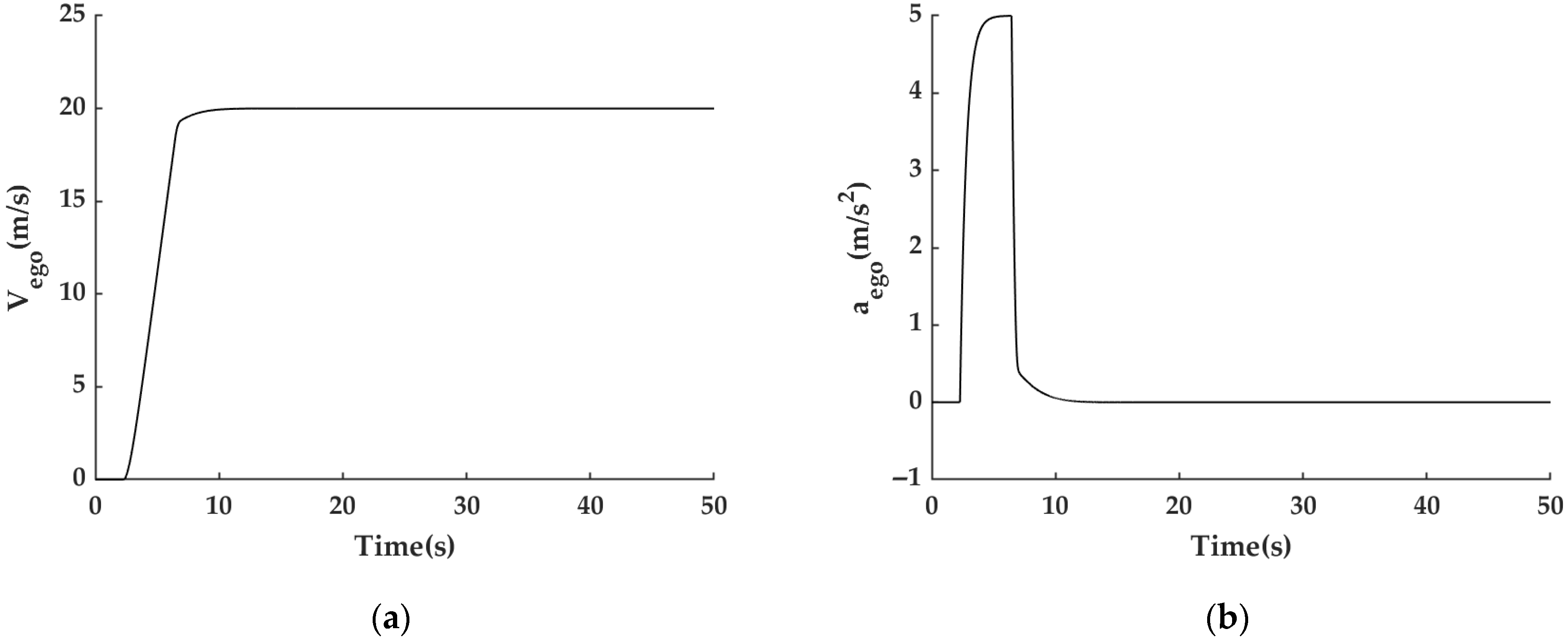
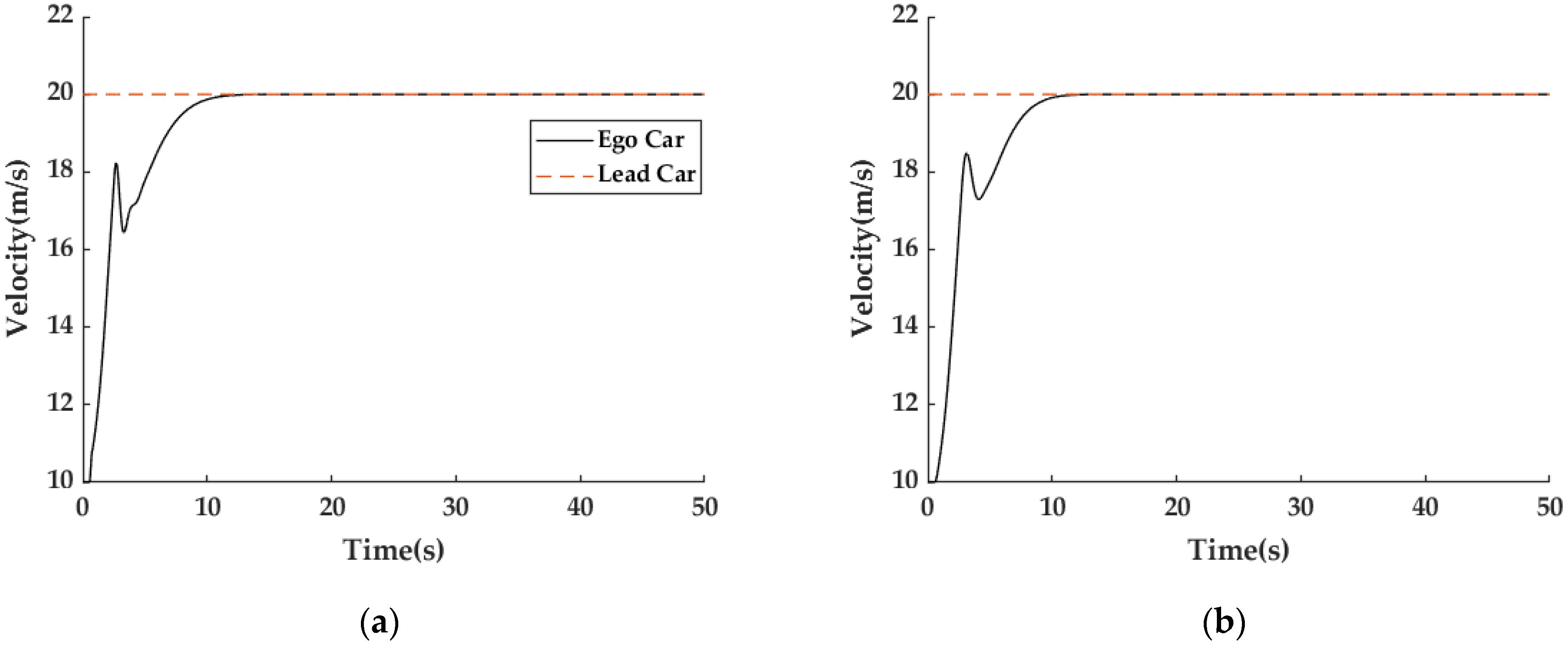
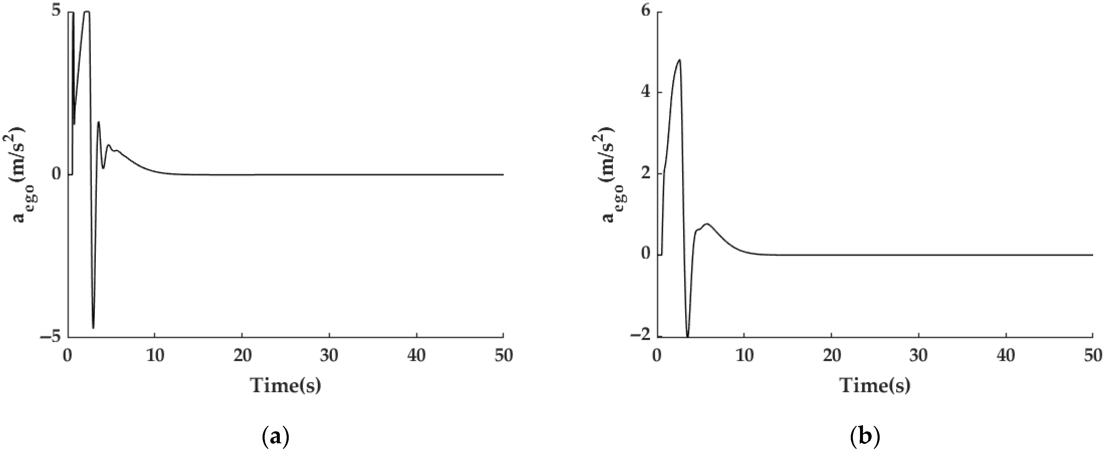
3.2.2. ACC Simulation

The ACC simulation is conducted using the MPC parameters listed in Table 2, with engineering constraints provided in Table 3.
First, a following scenario is simulated. The lead car traveled at a sinusoidal speed, while the ego car starts from an initial speed of 0 m/s with a desired speed of 30 m/s. The simulation results are shown in Figure 6. It can be observed that the lead car speed significantly affects the ego car acceleration, which undoubtedly further influences the vertical dynamic characteristics.
Then, the cruise with constant velocity simulation is conducted with the target speed set at 20 m/s. As shown in Figure 7, the controller effectively tracks the target speed and rapidly converges to 20 m/s, and the acceleration remains strictly within predefined constraints.

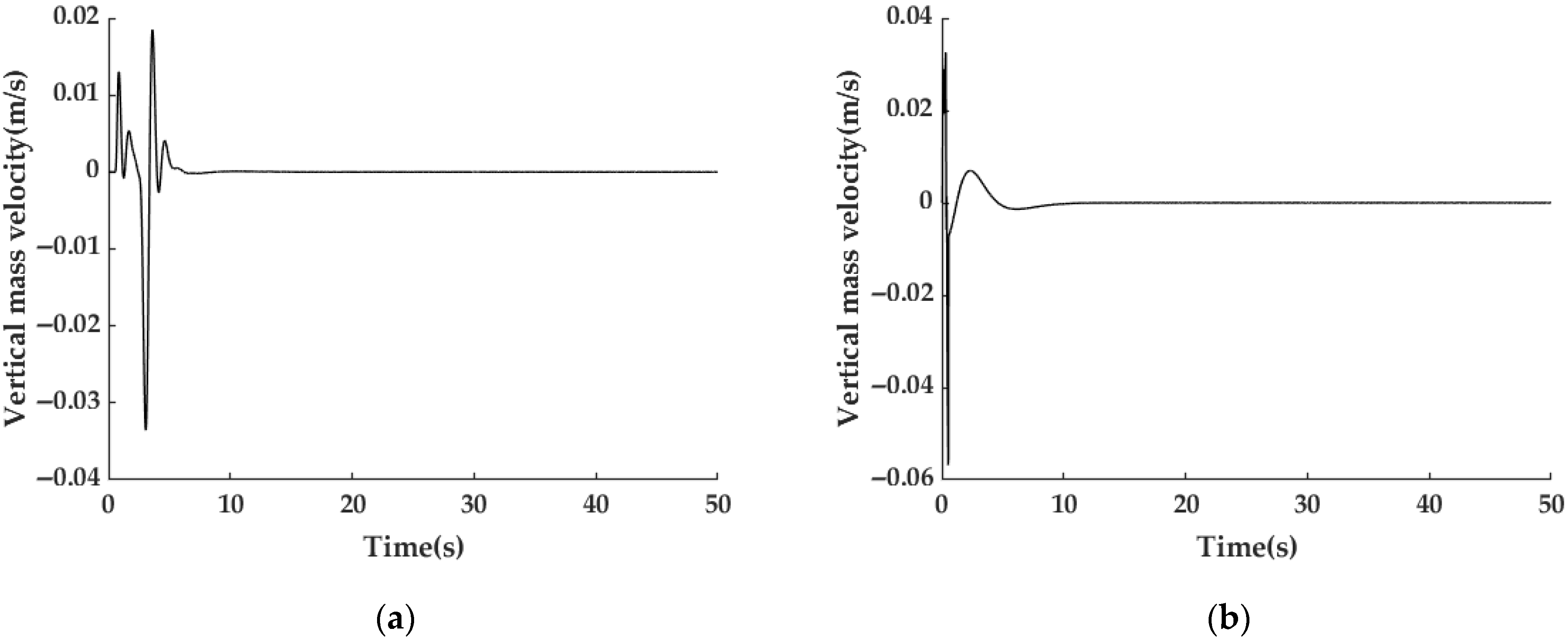
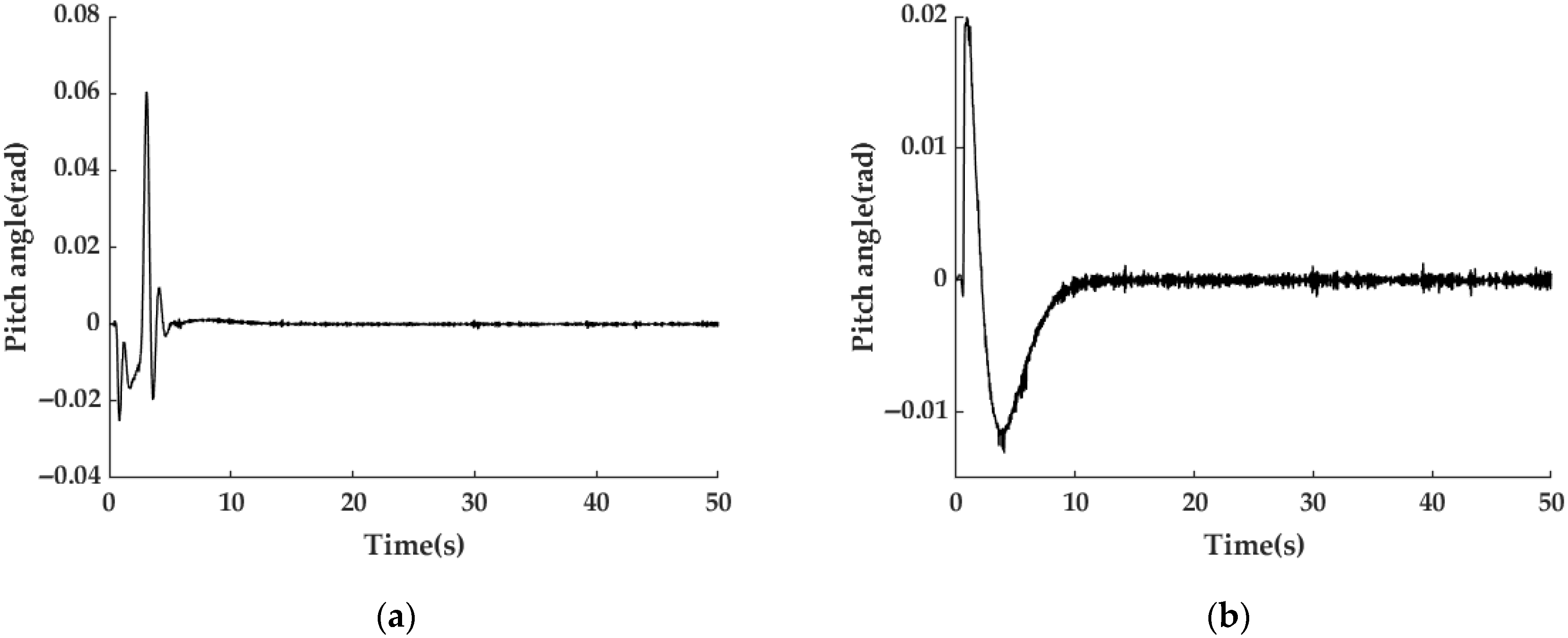
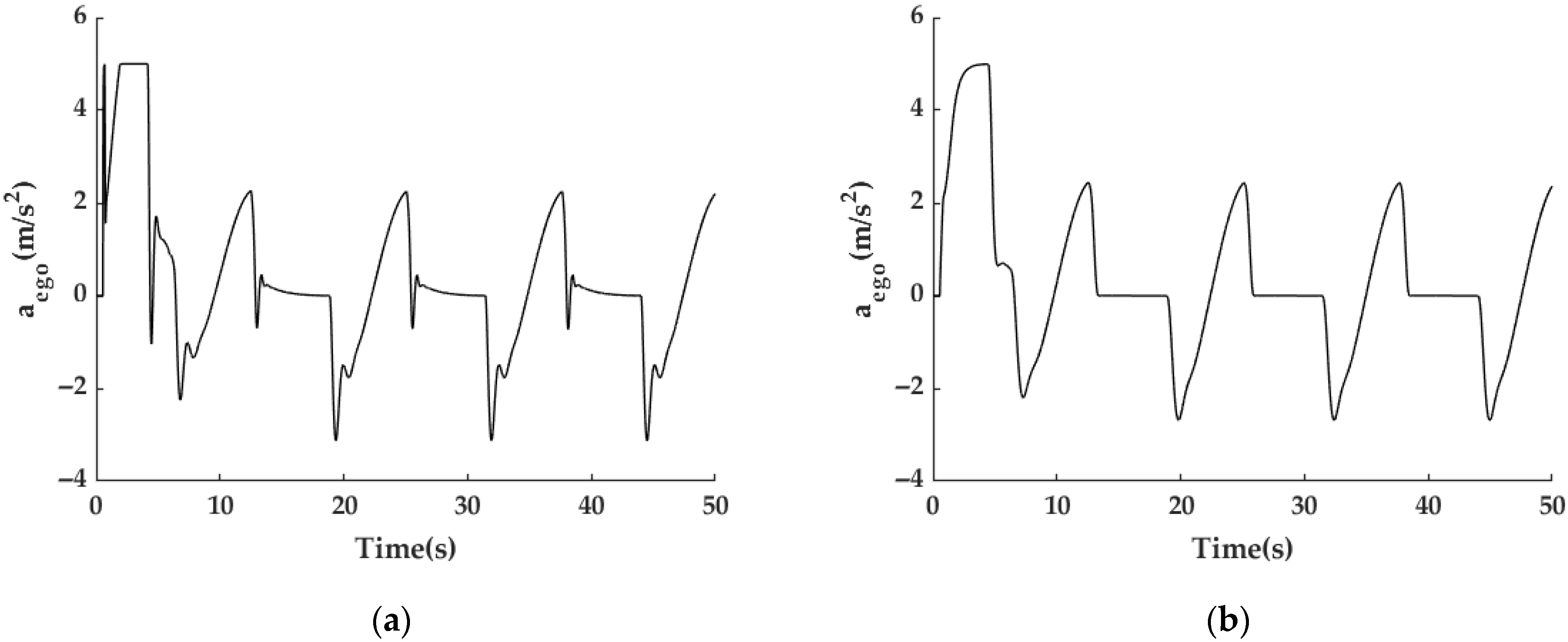
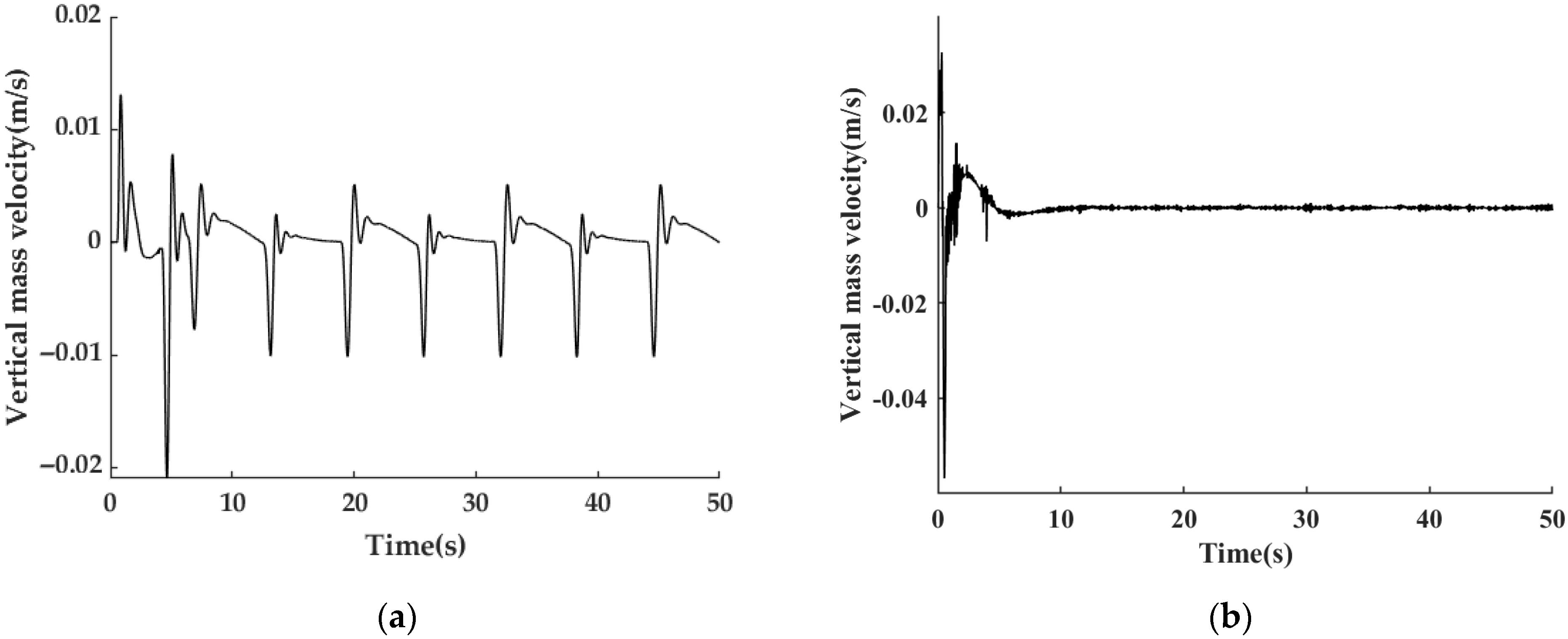
3.3. System Integrated Simulation

In conventional vehicle control architectures, ACC and suspension control systems typically operate in isolation. Therefore, this study first simulates such a decoupled control scheme as a baseline for comparison. Under this architecture, the acceleration computed by the ACC is treated as an external disturbance to the suspension control system, and suspension control performance does not feedback to influence the ACC acceleration.
In contrast, in the proposed control framework, the acceleration command of the ACC serves as a control variable in the integrated controller, introducing coupling with suspension dynamics, optimization of suspension performance consequently affects the vehicle’s acceleration.
A simulation is conducted under steady-state following conditions: lead car velocity is 20 m/s; initial distance between lead car and ego car is 100 m; ego car initial velocity is 10 m/s; both front and rear suspensions are subjected to Class B road excitation.
As evident from Figure 8, Figure 9, Figure 10 and Figure 11, the proposed integrated control strategy demonstrates significant improvements over decoupled control, longitudinal acceleration is effectively reduced, vertical velocity amplitude decreased at most time, pitch angle peak value reduced from 0.06 rad to 0.02 rad, and vehicle pitch dynamics caused by acceleration are effectively suppressed.
A simulation is conducted under car-following conditions: lead car velocity is a sinusoidal waveform with amplitude of 5 m/s, offset of 30 m/s, and frequency of 0.5 Hz; ego car initial velocity is 10 m/s, target velocity is 30 m/s, distance between lead car and ego car is 100 m, and both front and rear suspensions are subjected to Class B road excitation. As evidenced in Figure 12, Figure 13, Figure 14 and Figure 15, the proposed controller reliably maintains core ACC objectives under complex car-following conditions, specifically lead car tracking. Figure 13 demonstrates concurrent optimization of acceleration characteristics, in which the acceleration transition is smoother, and peak values are reduced. In Figure 14 and Figure 15, both vertical velocity and pitch angle are much smaller and smoother than decoupled control, and the disturbance induced by the lead car sinusoidal acceleration is nearly eliminated, achieving near-zero convergence within 10 s after initial oscillations, demonstrating marked superiority. The proposed control strategy demonstrates significant improvements over conventional decoupled control, consequently achieving effective mitigation of motion sickness.
RMS and MSDV of corresponding signals are calculated and compared, listing in Table 4. In Table 4, jerk describes the rate of change of vehicle acceleration over time and directly reflects the smoothness of acceleration variation. Excessive jerk can easily trigger passenger motion sickness, and wy is pitch angular velocity. MSDV is calculated based on the ISO 2631-1 standard [30].
RMS of parameter aego and jerk of the proposed method are obviously smaller than those of the decoupled method, especially jerk, and the proposed method can effectively regulate longitudinal dynamics and suppresses motion sickness-related parameters.
RMS of parameter Θy and wy are also significantly lower than those of decoupled control, indicating that the pitch motion induced by longitudinal acceleration has been effectively suppressed, thereby reducing the likelihood of motion sickness.
Parameter vsz exhibits counterintuitive data trends—both RMS and MSDV values of the proposed method are higher than those of the decoupled method. However, as shown in Figure 14 and Figure 15, this increase primarily stems from a rapid, large-magnitude signal fluctuation during the very initial control phase. This transient spike results in significantly higher short-term acceleration variations in the MSDV calculation, leading to an inflated MSDV value. Notably, such fluctuations occur only once at startup. From a long-term control perspective, the proposed method still demonstrates exceptionally superior performance.

4. Conclusions

This article proposes a vertical and longitudinal coupling control for vehicles, including active suspension control and ACC. The suspension control system is designed based on a half-car model, and the pitch dynamics of the sprung mass induced by acceleration are also incorporated into the model. In ACC design, acceleration command is one of the control variables optimizing ACC and suspension-related objectives. The coupled control system is designed based on MPC: three control inputs are active control forces of front and rear suspension, and longitudinal acceleration; eleven states are eight suspension states and three ACC states. The target outputs mainly focus on three variables related to motion sickness: vertical velocity and pitch angle of the sprung mass, and longitudinal acceleration of the vehicle. By designing a coupled controller, the acceleration can be adjusted during the suspension control process to suppress pitch motion and optimize the suspension control effect.
The simulation compares the conventional suspension and ACC decoupled control with the proposed coupled method. The results demonstrate that (1) longitudinal acceleration will affect the suspension control effect, thereby exacerbating the parameters related to motion sickness; (2) the proposed coupling controller can optimize suspension control performance by adjusting acceleration while meeting the original objectives of ACC, thereby suppressing motion sickness-related parameters. The proposed method explores the performance of multi-dimensional coupling control of the chassis in terms of motion-related comfort and provides a feasible solution.
However, there are still some limitations to this study: (1) The nonlinear characteristics of the active suspension actuator have not been taken into account, which have a significant impact on suspension performance. Neglecting these factors may result in poor performance of the controller under actual operating conditions, especially under large-amplitude or high-frequency excitations, where the dynamic response of the suspension deviates significantly from the theoretical model, thereby affecting vehicle comfort and stability. (2) This study focuses on vehicle dynamics performance indicators, while motion sickness-related physiological signals (e.g., passenger head acceleration, EEG and visual–vestibular conflict) were not directly included in the optimization objectives, this may result in the control system improving mechanical performance but failing to effectively alleviate passenger motion issues. (3) Motion sickness is caused by the coupled effects of longitudinal, lateral, and vertical dynamics, and may have a cumulative effect; this study mainly focuses on longitudinal–vertical coupling dynamics, ignoring the lateral dynamics and cumulative effect of signals, which may result in inaccurate control effect in real driving conditions.
In future research, we will focus on the following aspects: (1) integrate the nonlinear actuator model into the control system to improve model accuracy; (2) develop a human mechanical model and establish the mathematical relationship between physiological indicators and control signals, directly using acceleration and other signals to regulate comfort metrics, achieving human–vehicle closed-loop control; (3) investigate longitudinal–lateral–vertical coupling control methods and identify the feasible spatial domain of control inputs to simultaneously manage three-dimensional dynamics, thus mitigating motion sickness.

Author Contributions

Conceptualization, F.Z.; methodology, D.Z.; software, Y.Z.; validation, F.Z. and Y.Z.; formal analysis, J.J.; investigation, P.W.; resources, Z.F.; writing—original draft preparation, F.Z.; writing—review and editing, Z.W.; funding acquisition, Z.F. All authors have read and agreed to the published version of the manuscript.

Funding

This research was funded by Henan Natural Science Fund for Distinguished Young Scholars, grant number 252300421015, National Natural Science Foundation of China (NSFC), grant number 52472441, and Henan Center for Outstanding Overseas Scientists, grant number GZS2023011, Major Science and Technology Projects in Henan Province, grant number 241100240300, Henan Provincial Science and Technology Tackling Project, grant number 252102220101, Natural Science Foundation in Henan province of China, grant Number 242300421468.

Data Availability Statement

The dataset used in this research is available upon request by emailing the corresponding author.

Conflicts of Interest

The authors declare no conflicts of interest.

Abbreviations

The following abbreviations are used in this manuscript:
EVsElectric Vehicles
AVsAutonomous Vehicles
VRVirtual Reality
EGGElectrogastrography
EEGElectroencephaogram
AFSActive Front Steering
ASSActive-suspension System
MDMPCMulti-constrained Distributed Model Predictive Control
SSQSimulator Sickness Questionnaire
MSIMotion Sickness Incidence
MSDV Motion Sickness Dose Value
EDAElectrodermal activity
WBVWhole-body Vibration
LMILinear Matrix Inequality
MOGAMulti-objective Genetic Algorithm
DRLDeep Reinforcement Learning
ADASAdvanced Driving Assistance System
MPCModel Predictive Control
QPQuadratic Programming
MIMOMultiple-Input Multiple-Output

References

  1. Diels, C.; Ye, Y.; Bos, J.E.; Maeda, S. Motion Sickness in Automated Vehicles: Principal Research Questions and the Need for Common Protocols. SAE Int. J. Connect. Autom. Veh. 2022, 5, 121–134. [Google Scholar] [CrossRef]
  2. Li, Z.H.; Khajepour, A.; Song, J.C. A comprehensive review of the key technologies for pure electric vehicles. Energy 2019, 182, 824–839. [Google Scholar] [CrossRef]
  3. Zheng, Y.G.; Shyrokau, B.; Keviczky, T. Mitigating Motion Sickness With Optimization-Based Motion Planning. IEEE Trans. Intell. Veh. 2024, 9, 2553–2563. [Google Scholar] [CrossRef]
  4. Shi, Z.S.; He, L.; Wang, M.W.; Bian, Y.J.; Cui, S.H.; Chen, P.P. Ideal comfort ellipses and comfort dynamics model for mitigating motion sickness in battery electric vehicle. In Vehicle System Dynamics; Taylor & Francis: Abingdon, UK, 2024. [Google Scholar]
  5. Asua, E.; Gutiérrez-Zaballa, J.; Mata-Carballeira, O.; Ruiz, J.A.; del Campo, I. Analysis of the Motion Sickness and the Lack of Comfort in Car Passengers. Appl. Sci. 2022, 12, 3717. [Google Scholar] [CrossRef]
  6. Keshavarz, B.; Golding, J.F. Motion sickness: Current concepts and management. Curr. Opin. Neurol. 2022, 35, 107–112. [Google Scholar] [CrossRef] [PubMed]
  7. Laessoe, U.; Abrahamsen, S.; Zepernick, S.; Raunsbaek, A.; Stensen, C. Motion sickness and cybersickness—Sensory mismatch. Physiol. Behav. 2023, 258, 114015. [Google Scholar] [CrossRef] [PubMed]
  8. Ng, A.K.T.; Chan, L.K.Y.; Lau, H.Y.K. A study of cybersickness and sensory conflict theory using a motion-coupled virtual reality system. Displays 2020, 61, 101922. [Google Scholar] [CrossRef]
  9. Gruden, T.; Popovic, N.B.; Stojmenova, K.; Jakus, G.; Miljkovic, N.; Tomazic, S.; Sodnik, J. Electrogastrography in Autonomous Vehicles-An Objective Method for Assessment of Motion Sickness in Simulated Driving Environments. Sensors 2021, 21, 550. [Google Scholar] [CrossRef]
  10. Huang, J.; Liu, X.Z.; Hu, L. Review of Motion Sickness-associated Comfort Studies for Occupants in Autonomous Vehicles. China J. Highw. Transp. 2024, 37, 356–369. [Google Scholar]
  11. Brietzke, A.; Xuan, R.P.; Dettmann, A.; Bullinger, A.C. Influence of dynamic stimulation, visual perception and individual susceptibility to car sickness during controlled stop-and-go driving. Forsch. Ingenieurwes 2022, 12, 3717. [Google Scholar] [CrossRef]
  12. Deng, Z.X.; Yuan, K.; Xiao, X. Investigative examination of motion sickness indicators for electric vehicles. Proc. Inst. Mech. Eng. Part D J. Automob. Eng. 2025, 239, 3347–3357. [Google Scholar] [CrossRef]
  13. Zhao, S.E.; Tian, Z.S.; Wei, H.b.B.; Xiao, X.; Wang, K.; Zeng, J. Evaluation Model of Passenger Motion Sickness Based on Vehicle Motion Parameters. China J. Highw. Transp. 2025, 38, 274–285. [Google Scholar]
  14. Tian, Z.S.; Zhao, S.E.; Xiao, X.; Wei, H.B.; Wang, K.; Zeng, J. Evaluation of intelligent electric vehicle carsickness performance considering passenger motion sensitivity. Proc. Inst. Mech. Eng. Part D J. Automob. Eng. 2025. [Google Scholar]
  15. Iskander, J.; Attia, M.; Saleh, K.; Nahavandi, D.; Abobakr, A.; Mohamed, S.; Asadi, H.; Khosravi, A.; Lim, C.P.; Hossny, M. From car sickness to autonomous car sickness: A review. Transp. Res. Part F Traffic Psychol. Behav. 2019, 62, 716–726. [Google Scholar] [CrossRef]
  16. Kia, K.; Johnson, P.W.; Kim, J.H. The effects of different seat suspension types on occupants? physiologic responses and task performance: Implications for autonomous and conventional vehicles. Appl. Ergon. 2021, 93, 103380. [Google Scholar] [CrossRef] [PubMed]
  17. Jin, S.; Lee, C.; Rhee, E.; Jung, J.; Lee, C. Analysis of the Effects of Motion Sickness According to Damping Characteristics of Suspension. Int. J. Auto. Technol. 2025, 26, 991–999. [Google Scholar] [CrossRef]
  18. Cui, M.; Fu, Z.J.; Rakheja, S.; Zhen, R.; Liu, Y.G. Adaptive Preview H. Control of Active Suspension Based on Road Recognition. Automot. Eng. 2025, 47, 508–518. [Google Scholar]
  19. Chen, X.K.; Wang, H.Y.; Liu, H.Y.; Liu, X. Research on Coordinated Control of Semi-active Suspension of Intelligent Chassis and Ground Tangential Force. J. Mech. Eng. 2024, 60, 1–10. [Google Scholar]
  20. Feng, J.W.; Liang, J.H.; Lu, Y.B.; Zhuang, W.C.; Pi, D.W.; Yin, G.D.; Xu, L.W.; Peng, P.; Zhou, C.B. An Integrated Control Framework for Torque Vectoring and Active Suspension System. Chin. J. Mech. Eng. 2024, 37, 10. [Google Scholar] [CrossRef]
  21. Liang, J.H.; Lu, Y.B.; Pi, D.W.; Yin, G.D.; Zhuang, W.C.; Wang, F.A.; Feng, J.W.; Zhou, C.B. A Decentralized Cooperative Control Framework for Active Steering and Active Suspension: Multi-Agent Approach. IEEE Trans. Transp. Electrif. 2022, 8, 1414–1429. [Google Scholar] [CrossRef]
  22. Zheng, Y.G.; Shyrokau, B.; Keviczky, T.; Al Sakka, M.; Dhaens, M. Curve Tilting with Nonlinear Model Predictive Control for Enhancing Motion Comfort. IEEE Trans. Control Syst. Technol. 2022, 30, 1538–1549. [Google Scholar] [CrossRef]
  23. Winkel, K.N.D.; Irmak, T.; Happee, R.; Shyrokau, B. Standards for passenger comfort in automated vehicles: Acceleration and jerk. Appl. Ergon. 2023, 106, 103881. [Google Scholar] [CrossRef]
  24. Htike, Z.; Papaioannou, G.; Siampis, E.; Velenis, E.; Longo, S. Fundamentals of Motion Planning for Mitigating Motion Sickness in Automated Vehicles. IEEE Trans. Veh. Technol. 2022, 71, 2375–2384. [Google Scholar] [CrossRef]
  25. Geng, G.Q.; Wu, Z.; Jiang, H.B.; Sun, L.Q.; Duan, C. Study on Path Planning Method for Imitating the Lane-Changing Operation of Excellent Drivers. Appl. Sci. 2018, 8, 814. [Google Scholar] [CrossRef]
  26. Li, D.F.; Hu, J.K. Mitigating Motion Sickness in Automated Vehicles with Frequency-Shaping Approach to Motion Planning. IEEE Robot. Autom. Lett. 2021, 6, 7714–7720. [Google Scholar] [CrossRef]
  27. Rajesh, N.; Zheng, Y.G.; Shyrokau, B. Comfort-Oriented Motion Planning for Automated Vehicles Using Deep Reinforcement Learning. IEEE Open J. Intell. Transp. Sys. 2023, 4, 348–359. [Google Scholar] [CrossRef]
  28. Gysen, B.L.J.; Paulides, J.J.H.; Janssen, J.L.G.; Lomonova, E.A. Active Electromagnetic Suspension System for Improved Vehicle Dynamics. IEEE Trans. Veh. Technol. 2010, 59, 1156–1163. [Google Scholar] [CrossRef]
  29. Papaioannou, G.; Ning, D.H.; Jerrelind, J.; Drugge, L. A K-Seat-Based PID Controller for Active Seat Suspension to Enhance Motion Comfort. SAE Int. J. Connect. Autom. Veh. 2022, 5, 189–199. [Google Scholar] [CrossRef]
  30. ISO 2631-1:1997; Mechanical Vibration and Shock—Evaluation of Human Exposure to Whole-Body Vibration—Part 1: General Requirements. International Organization for Standardization: Geneva, Switzerland, 1997.
Figure 1. Half-car suspension model.
Machines 13 00650 g001
Figure 2. ACC principle.
Machines 13 00650 g002
Figure 3. MPC principle.
Machines 13 00650 g003
Figure 4. Integrated control architecture.
Machines 13 00650 g004
Figure 5. Suspension control simulation: (a) sprung mass vertical velocity; (b) sprung mass pitch angle.
Machines 13 00650 g005
Figure 6. Car-following simulation: (a) velocity comparison of ego car and lead car; (b) acceleration of ego car.
Machines 13 00650 g006
Figure 7. Constant speed simulation: (a) velocity of ego car; (b) acceleration of ego car.
Machines 13 00650 g007
Figure 8. Comparison of ego car velocity: (a) decoupled control; (b) proposed control.
Machines 13 00650 g008
Figure 9. Comparison of ego car acceleration: (a) decoupled control; (b) proposed control.
Machines 13 00650 g009
Figure 10. Comparison of ego car sprung mass vertical velocity: (a) decoupled control; (b) proposed control.
Machines 13 00650 g010
Figure 11. Comparison of ego car pitch angle: (a) decoupled control; (b) proposed control.
Machines 13 00650 g011
Figure 12. Comparison of velocity: (a) decoupled control; (b) proposed control.
Machines 13 00650 g012
Figure 13. Comparison of acceleration: (a) decoupled control; (b) proposed control.
Machines 13 00650 g013
Figure 14. Comparison of sprung mass vertical velocity: (a) decoupled control; (b) proposed control.
Machines 13 00650 g014
Figure 15. Comparison of pitch angle: (a) decoupled control; (b) proposed control.
Machines 13 00650 g015
Table 1. Parameters of the vehicle.
ParameterValue
ms1200 kg
Iy1500 kg·m2
mus140 kg
mus145 kg
ks125,000 N/m
ks227,000 N/m
cs11500 N·s/m
cs21600 N·s/m
kt1200,000 N/m
kt2210,000 N/m
lf1.2 m
lr1.5 m
hg0.5 m
Table 2. MPC parameters.
HyperparameterValue
Discretization Period0.02 s
Prediction Horizon30
Control Horizon20
Table 3. Input/output constraints.
ParameterMin.Max.
F1−2000 N2000 N
F22000 N2000 N
acmd−5 m/s25 m/s2
z ˙ s −0.3 m/s0.3 m/s
θ−8·π/180 rad8·π/180 rad
θ ˙ −3·π/180 rad/s3·π/180 rad/s
zs1zus1−0.1 m0.1 m
zs2zus2−0.1 m0.1 m
d50 m250 m
vego0 m/s50 m/s
aego−5 m/s25 m/s2
Table 4. RMS and MSDV comparison.
Driving ConditionParameterMethodRMSMSDV
Vlead: constantaegodecoupled0.936/
coupled 0.846/
jerkdecoupled4.18/
coupled 1.39/
θydecoupled0.0057/
coupled 0.0036/
vszdecoupled0.00320.0295
coupled 0.00330.1696
wydecoupled0.03/
coupled 0.018/
Vlead: sinusoidalaegodecoupled1.72/
coupled 1.68/
jerkdecoupled4.4/
coupled 1.72/
θydecoupled0.0068/
coupled 0.0035/
vszdecoupled0.00310.0255
coupled 0.00380.1721
wydecoupled0.0296/
coupled 0.0176/
Disclaimer/Publisher’s Note: The statements, opinions and data contained in all publications are solely those of the individual author(s) and contributor(s) and not of MDPI and/or the editor(s). MDPI and/or the editor(s) disclaim responsibility for any injury to people or property resulting from any ideas, methods, instructions or products referred to in the content.

