Article

A Novel Flow Characteristic Regulation Method for Two-Stage Proportional Valves Based on Variable-Gain Feedback Grooves

by
Xingyu Zhao
,
Huaide Geng
,
Long Quan
*,
Chengdu Xu
,
Bo Wang
and
Lei Ge
*
Key Lab of Advanced Transducers and Intelligent Control System of Ministry of Education, Taiyuan University of Technology, Taiyuan 030024, China
*
Authors to whom correspondence should be addressed.
Machines 2025, 13(8), 648; https://doi.org/10.3390/machines13080648
Submission received: 11 June 2025 / Revised: 21 July 2025 / Accepted: 22 July 2025 / Published: 24 July 2025
(This article belongs to the Section Machine Design and Theory)

Abstract

The two-stage proportional valve is a key control component in heavy-duty equipment, where its signal-flow characteristics critically influence operational performance. This study proposes an innovative flow characteristic regulation method using variable-gain feedback grooves. Unlike conventional throttling notch optimization, the core mechanism actively adjusts pilot–main valve mapping through feedback groove shape and area gain adjustments to achieve the desired flow curves. This approach avoids complex throttling notch issues while retaining the valve’s high dynamics and flow capacity. Mathematical modeling elucidated the underlying mechanism. Subsequently, trapezoidal and composite feedback grooves are designed and investigated via simulation. Finally, composite feedback groove spools tailored to construction machinery operating conditions are developed. Comparative experiments demonstrate the following: (1) Pilot–main mapping inversely correlates with area gain; increasing gain enhances micro-motion control, while decreasing gain boosts flow gain for rapid actuation. (2) This method does not significantly increase pressure loss or energy consumption (measured loss: 0.88 MPa). (3) The composite groove provides segmented characteristics; its micro-motion flow gain (2.04 L/min/0.1 V) is 61.9% lower than conventional valves, significantly improving fine control. (4) Adjusting groove area gain and transition point flexibly modifies flow gain and micro-motion zone length. This method offers a new approach for high-performance valve flow regulation.

1. Introduction

As a core control component in hydraulic systems, proportional valves regulate and distribute flow to drive actuator motion [1]. They are widely used in aerospace, heavy machinery, robotics, and energy equipment [2]. Single-stage proportional valves typically employ electro-mechanical conversion units for direct spool actuation. However, limited by the performance of proportional solenoids, single-stage valves are primarily suitable for low-flow systems and struggle to meet high-flow operational demands [3]. This limitation has driven the development of two-stage proportional valves, which leverage a small-flow pilot valve to regulate a large-diameter main valve [4].
These valves are categorized by a control method into three types: displacement–electrical feedback, displacement–force feedback, and displacement–hydraulic feedback [5]. The displacement–hydraulic feedback configuration (pioneered by Andersson) establishes a characteristic mapping relationship between the main and pilot valves through specialized hydraulic circuit design [6]. The Valvistor valve derives its name from the main valve flow being proportionally amplified relative to pilot flow. EATON commercialized this principle through a full line of Valvistor valves, offering compact design, high flow capacity, and superior dynamics at low cost [7]. Extensive research has focused on enhancing the control performance of proportional valves, achieving high-precision flow regulation through pressure compensators, multi-sensor closed-loop control [8], and artificial neural networks [9]. Concurrently, significant progress has been made in valve structural optimization. Zhao et al. [10] developed a displacement–hydraulic feedback valve utilizing a high-speed switching pilot valve for coal mine hydraulic supports. Huang et al. demonstrated that widening feedback grooves improves dynamic response but reduces stability [11]. Hao et al. found that enlarging the feedback groove pre-opening distances increased stability at the expense of dead zone expansion [12]. However, existing studies exclusively employ rectangular feedback grooves; the geometric evolution of groove profiles and systematic methodologies for regulating the pilot–main valve mapping relationship remain unexplored.
Flow is a core hydraulic parameter, directly determining actuator velocity and displacement [13]. For flow control components like two-stage proportional valves, the control signal-flow characteristic curve critically influences equipment maneuverability and operational adaptability [14]. This curve often requires customized design based on actual operating conditions. For instance, construction machinery (e.g., cranes, loaders) demands proportional valves with multi-stage flow regulation to achieve both smooth starting and rapid motion [15]. Since flow depends on orifice area and pressure difference [16], researchers regulate flow characteristics through two primary approaches: (1) optimizing main valve throttling notch geometry [17], and (2) actively controlling pressure difference.
In the study of throttling notch shapes, common single-stage configurations include U-shaped, triangular, and rectangular notches. Research has shown that the geometry of throttling notches significantly affects valve performance characteristics, such as flow rate, jet angle, steady-state flow force, and throttling stiffness [18]. Ye et al. [19] conducted a comparative study of U-shaped, spherical, and triangular notches, finding that the triangular notch exhibited the highest throttling stiffness and the smallest flow force. Subsequently, Ye et al. [20] introduced a gradually expanding U-notch, which outperformed spherical and triangular designs in balancing sensitivity and stability. Pan et al. [21] developed a generalized mathematical model for throttling notches applicable to both laminar and turbulent flow regimes. Further investigating typical O-shaped, U-shaped, and C-shaped notches, Zhang et al. [22] found that flow coefficients remain constant with small openings but decline linearly with area when fully open. Muniak et al. proposed a valve spool geometric design methodology accounting for internal clearance constraints [23], ensuring stable control characteristics [24].
To enhance the micro-motion performance and adaptability of valves to various operating conditions, complex profiled and combined notches have emerged. Borghi et al. [25] experimentally compared the flow characteristics of U-shaped, triangular, and triple-U combined notches, revealing that the shape and number of notches directly affected the saturation value of the flow coefficient. Li et al. [26] demonstrated that triangular–rectangular combined notches optimize fine control in two-stage valves. Qian et al. [27] compared the flow characteristics of spherical, frustum, and ellipsoidal spool structures, noting that the flow coefficient varied significantly among different notch shapes. In the area of complex profiled throttling notches, Yuan et al. [28] derived a cavitation characteristic calculation formula for profiled notches. Kong et al. [29] demonstrated through flow visualization that rounded expanding notches enhance flow control linearity while reducing pressure loss.
However, notch geometry critically influences flow forces and cavitation [30]. Ji et al. [31] revealed that jet angles decrease with valve opening size, with U-notches exhibiting larger variations than V-notches. Simic et al. [32] identified 60° as the optimal cone angle for minimizing poppet valve flow forces. Furthermore, Shangguan et al. [33] proposed a sloping U-shaped throttling notch that yields a 37.57% reduction in flow forces compared to conventional U-notches. Regarding cavitation, miniature profiled notches under small-opening/high-pressure conditions trigger pressure surges and noise [34]. Frosina et al. [35] employed transparent valve bodies combined with experiments and CFD to study U-notch cavitation. Zou et al. [36] and Jia et al. [37] found that greater notch depths increase the cavitation index and intensify cavitation. Du et al. [38] discovered that cavitation occurs near the throttling edge’s high-shear zones in V-shaped notches under small openings. Li et al. [39] compared cavitation in cone valves with different angles, noting severe cavitation at large pressure drops, with 60° cones exhibiting minimal cavitation noise.
Recent studies have proposed active control of orifice pressure difference as a method for flow characteristic regulation [40]. Zhao et al. [41] integrated motors and ball screws into pressure-compensating valves. By altering the spool force equilibrium, they achieved programmable adjustment of the flow characteristic curve without modifying the main valve structure. Similarly, Wang et al. [42] achieved real-time pressure regulation using dual proportional pressure-reducing valves and a spool land, enabling complex flow characteristics with simple notches.
Despite extensive research on throttling notch optimization and active pressure difference regulation, several aspects require improvement:
(1)
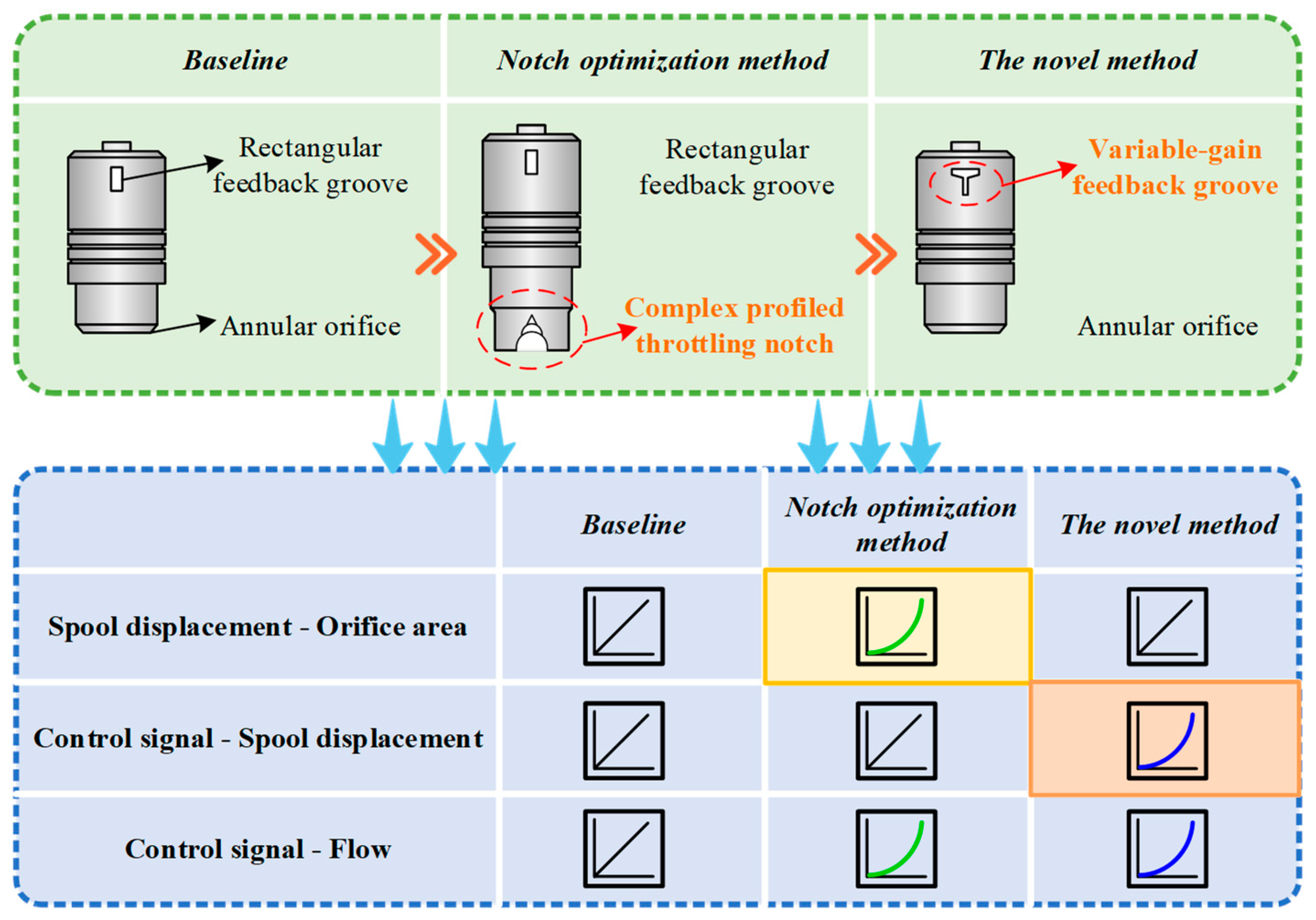
Insufficient research on flow characteristic regulation based on pilot–main valve mapping: Existing studies rarely optimize flow characteristics by leveraging this core mapping relationship in two-stage proportional valves.
(2)
Limitations of notch optimization methods: Although complex-shaped throttling notches improve micro-motion performance, they are limited by their high manufacturing cost and difficulty. These designs increase pressure loss, energy consumption, and cavitation risks. In particular, for Valvistor valves with cone structures, machining complex notches is more challenging than for spool valves and increases the main valve stroke, thereby degrading dynamic response.
(3)
Cost and complexity of active pressure difference regulation: This approach necessitates additional electromechanical components, which significantly increases system cost and structural complexity.
This study focuses on the Valvistor valve and proposes a novel flow characteristic regulation method based on variable-gain feedback grooves. The core innovation involves actively modulating the pilot-main spool displacement mapping via specifically designed variable-gain feedback grooves. This approach enables customized flow curves without altering the throttling notch structure of the main valve spool (Figure 1). Fundamentally distinct from existing solutions—such as regulating the main valve orifice area or pressure difference—this mechanism establishes a novel paradigm for flow control in two-stage valves. Compared with throttling notch optimization methods, the proposed technique eliminates reliance on complex profiled notches while preserving the inherent advantages of Valvistor valves (e.g., low cost, high dynamics, low pressure loss) and enabling flexible flow regulation. Moreover, it avoids the adverse effects associated with complex notches, such as increased energy consumption, cavitation risks, and degraded dynamic response. Furthermore, relative to active pressure-difference regulation, it requires no additional devices or electromechanical units, offering significant advantages in structural simplicity and cost-effectiveness.
The paper is structured as follows: Section 2 describes the Valvistor valve’s operating principle and defines the feedback groove’s geometric parameters. Section 3 develops the mathematical model for analysis of the variable-gain feedback mechanism. Section 4 presents a multidisciplinary co-simulation model to evaluate the static/dynamic characteristics of valves with different feedback groove geometries, further examining how geometric parameters affect main valve behavior. Section 5 presents prototype spools with variable-gain feedback grooves for experimental verification. Section 6 and Section 7 concludes the study and outlines future research directions.

2. Working Mechanism

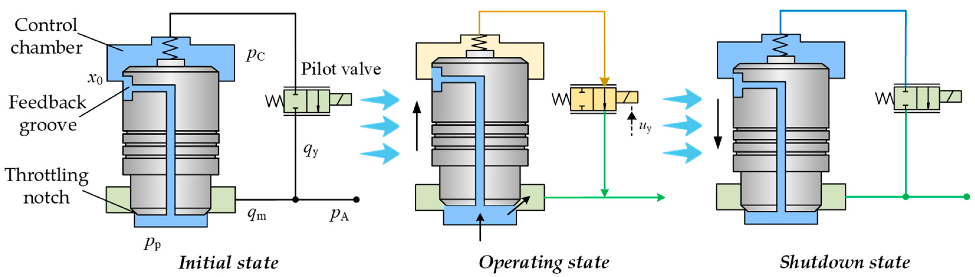
2.1. Working Principle of the Two-Stage Proportional Valve

The operating principle of the Valvistor valve is shown in Figure 2. This proportional valve consists of a pilot valve and a main valve. The pilot valve is directly controlled by a proportional solenoid, while the main valve adopts a cartridge structure with an internal feedback groove that enables displacement–flow feedback. The working sequence occurs as follows:
(1)
Initial state:
The solenoid is de-energized, and the pilot valve remains closed. Inlet fluid enters the main valve control chamber through the pre-opening of the feedback groove. At this stage, control chamber pressure equals inlet pressure, causing the main spool to close under the combined action of differential area force and spring.
(2)
Operating state:
When a control signal energizes the pilot valve, electromagnetic force overcomes the pilot spring force to open the pilot orifice. Fluid in the control chamber flows to the main valve outlet through the pilot valve, reducing control pressure. The main spool moves upward until flow through the feedback groove equals pilot flow. At this equilibrium position, the main flow shows proportional amplification relative to the pilot flow, and the spool remains stationary.
(3)
Shutdown state:
When the proportional solenoid is de-energized, the pilot valve returns to its initial position via spring force, followed by the closure of the main valve orifice.

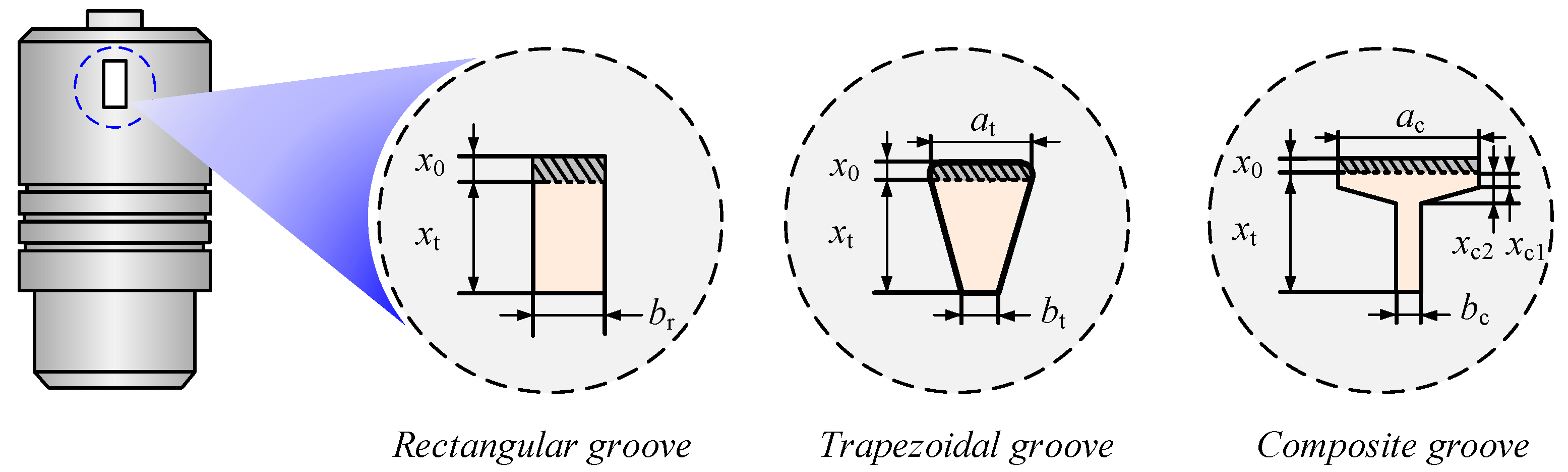
2.2. Design of the Variable-Gain Feedback Groove

As demonstrated in Section 2.1, the Valvistor valve operates with flow through the feedback groove equaling the pilot flow. This establishes a displacement mapping relationship between the pilot and main spools. Modifying the feedback groove geometry and area gain alters this displacement mapping, consequently changing the main valve’s spool displacement and flow characteristics. For identical control signals, higher feedback groove area gain reduces main spool displacement and flow output.
Conventional Valvistor valves employ rectangular feedback grooves with constant area gain, resulting in approximately proportional pilot–main displacement. To achieve the desired flow characteristics and enhance micro-motion performance, this study involves trapezoidal and composite variable-gain feedback grooves (Figure 3):
(1)
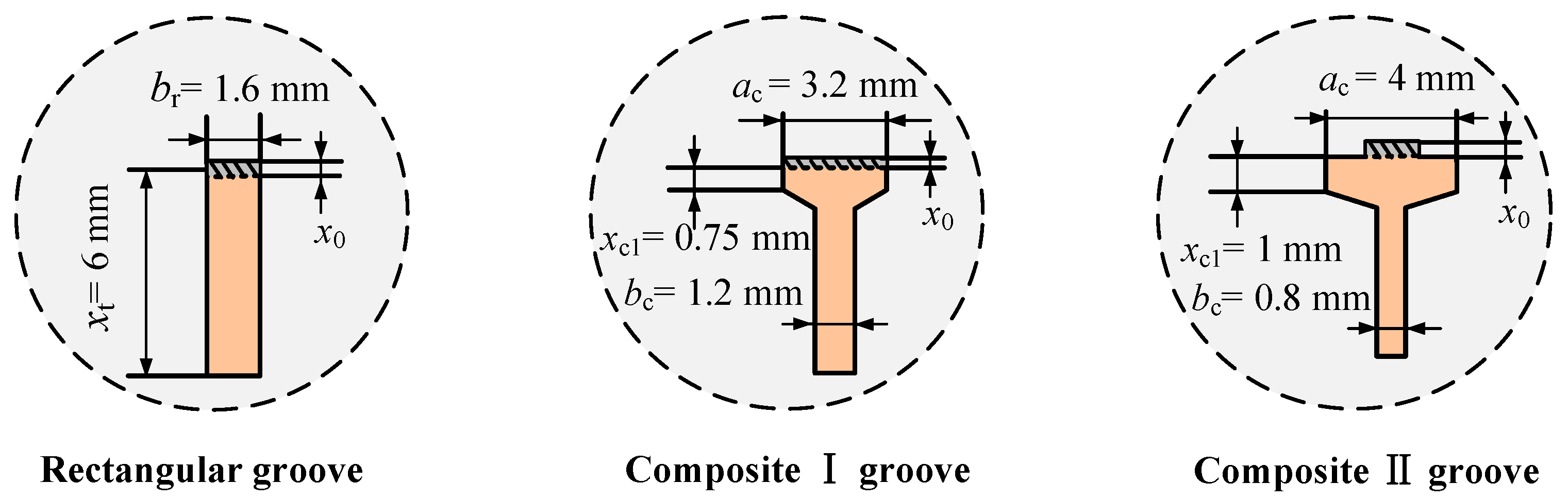
Trapezoidal groove: Features pre-opening length x0 (shaded area). Initial area gain exceeds terminal gain bt, with height xt. High initial gain promotes smooth actuator starting. As spool displacement increases, area gain decreases while displacement gain rises.
(2)
Composite groove: Combines two rectangles with different widths connected by a trapezoidal transition. The pre-opening of the composite groove is represented by x0, and the region from xc1 to xc2 serves as the transition zone. Pre-transition area gain ac exceeds post-transition gain bc. This configuration enables segmented flow control: the pre-transition zone optimizes fine control, while the post-transition zone provides rapid actuation with high flow gains.
Comparative analysis of rectangular, trapezoidal, and composite grooves follows two design principles: identical preliminary flow areas and equivalent total flow areas.

3. Mechanism of Feedback Groove Flow Regulation

3.1. Static Mathematical Model of the Two-Stage Proportional Valve

To analyze the flow regulation mechanism of feedback grooves, this study first establishes a static mathematical model of the two-stage proportional valve. This clarifies the characteristic mapping relationship between the pilot and main stages while examining the influence of feedback grooves on this mapping.
The pilot valve flow is expressed as
q y = C dy w y k e u y 2 p C p A ρ
where qy represents the pilot valve flow, Cdy denotes the pilot valve flow coefficient, wy represents the pilot valve orifice area gain, ke denotes the proportional solenoid gain, uy represents the pilot valve control voltage, pC represents the main valve control chamber pressure and pilot valve inlet pressure, pA denotes the main valve outlet pressure, and ρ is the fluid density.
The feedback groove flow is given by
q s = C ds w s ( x m + x 0 ) 2 ( p P p C ) ρ
where qs represents the feedback groove flow, Cds denotes the feedback groove flow coefficient, ws is the feedback groove area gain, x0 represents the feedback groove pre-opening, pP denotes the main valve inlet pressure, and xm is the main spool displacement.
The main valve flow equation is
q m = C dm w m x m 2 p P p A ρ
where qm represents the main valve flow, Cdm denotes the main valve flow coefficient, and wm is the main spool orifice area gain.
At equilibrium, flow through the feedback groove equals the pilot valve flow. Neglecting main spool spring force and steady-state flow force, Equations (1)–(3) yield the pilot–main displacement relationship:
x m = C dy w y C ds w s k e u y x 0
q m = C dm w m C ds w s ( 1 + x 0 x m ) q y
Equations (4) and (5) indicate that there is a mapping relationship between the main valve and pilot valve. By controlling the pilot valve, the main valve’s spool displacement and flow can be approximately proportionally controlled.
Further analysis reveals that the feedback groove directly affects the pilot–main-stage mapping relationship, leading to the feedback groove flow characteristic regulation mechanism. Without changing the orifice areas of the pilot and main valves, adjusting ws can regulate the main valve displacement gain and flow gain. A larger ws results in smaller displacement and flow gains, improving the valve’s fine motion characteristics. Conversely, a smaller ws leads to larger displacement and flow gains, facilitating rapid actuator driving.

3.2. Mathematical Model of Variable-Gain Feedback Grooves

3.2.1. Trapezoidal Feedback Groove

As shown in Figure 3, the area gain wst of a trapezoidal feedback groove is given by Equation (6):
w st = ( 1 x mt / x t ) a t + ( x mt / x t ) b t = a t ( a t b t ) x t x mt
where xmt represents the main spool displacement of the trapezoidal groove, at is the initial area gain, bt denotes the terminal area gain, and xt is the height of the trapezoidal groove.
Substituting Equation (6) into Equation (4) and ignoring the preopening of the feedback groove yields the main spool displacement xmt of the trapezoidal feedback groove valve:
x mt = C dy w y C ds w st k e u y = g xt u y
Equations (6) and (7) establish that the pilot-to-main-stage displacement mapping is governed by the variable-gain feedback groove through parameters at and bt. For trapezoidal grooves, the area gain (wst) decreases while the spool displacement gain (gxt) increases with main spool displacement (xmt). Consequently, higher wst and lower gxt at small displacements deliver enhanced system sensitivity per unit control signal, achieving superior fine-motion resolution.

3.2.2. Composite Feedback Groove

For the composite groove, Figure 3 shows its area gain wsc as
w sc = w s = a c x mc x c 1 ( 1 ( x mc x c 1 ) / ( x c 2 x c 1 ) ) a c + ( ( x mc x c 1 ) / ( x c 2 x c 1 ) ) b c x c 1 < x mc x c 2 b c x mc > x c 2
where xmc represents the main spool displacement of the composite groove, and xc1 is the inflection point. The region before xc1 is the micro-motion zone, between xc1 and xc2 is the transition zone, and after xc2 is the fast actuation zone. ac denotes the feedback groove area gain before the transition zone, and bc represents the gain after, where ac > bc.
Substituting Equation (8) into Equation (4) gives the main spool displacement xmc:
x mc = C dy w y C ds a c k e u y x mc x c 1 a c ( x c 2 x c 1 ) 2 ( a c b c ) a c 2 ( x c 2 x c 1 ) 2 4 ( a c b c ) 2 C dy w y ( x c 2 x c 1 ) k e u y C ds ( a c b c ) x c 1 < x mc x c 2 C dy w y C ds b c k e u y x mc > x c 2
Equations (8) and (9) show that the variable-gain feedback groove makes the main spool displacement a piecewise function with three zones. This design enables multi-stage flow control without altering the main valve throttling notches. Within the fine-motion region, the feedback groove exhibits high area gain ac, resulting in reduced main spool displacement gain and diminished flow gain. Conversely, in the rapid-drive region, the groove’s lower area gain bc yields elevated displacement gain and amplified flow gain.

3.3. Dynamic Mathematical Model of the Two-Stage Proportional Valve
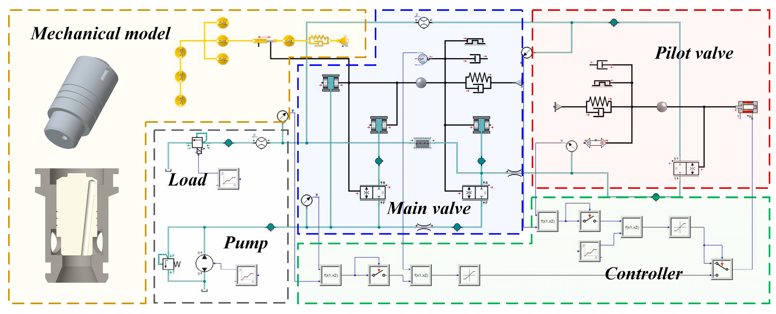
The stability of proportional valves critically influences equipment performance. External mechanical vibrations, system flow pulsations, and the structural parameters of the valve itself all impact stability. Research by Stosiak et al. demonstrates that external mechanical vibrations disrupt spool equilibrium [43] and further identifies the amplitude–frequency composition of hydraulic pressure pulsations [44]. Zhao et al. [45] assert that cavitation induces spool vibration, degrading control accuracy and exacerbating hysteresis.
Feedback groove parameters [11] directly affect the dynamic behavior and stability of two-stage proportional valves. Therefore, investigating their influence on stability and establishing a dynamic mathematical model is essential. To simplify analysis, the following well-justified assumptions are adopted in system modeling: (1) Negligible main spool spring force: The valve employs hydraulic resetting, with spring stiffness being sufficiently low for hydraulic forces to dominate. (2) The influence of flow forces is neglected. (3) Omitted solenoid dynamics: Response time is orders of magnitude faster than hydraulic timescales. (4) The effects of temperature on fluid properties are disregarded, and the hydraulic oil is assumed to be incompressible.
The dynamic equilibrium equation for the main spool is expressed as
p A 1 2 A C + p P 1 2 A C p C A C = m x ¨ m + B m x ˙ m
where AC represents the effective area at the upper end of the main spool (the upper-to-lower effective area ratio is 2:1), m is the main spool mass, and Bm denotes the viscous damping coefficient.
The flow continuity equation for the control chamber between the main valve and the pilot valve is
V C β p ˙ c = ( q s q y + A C x ˙ m )
where VC represents the control chamber volume, and is the bulk modulus of elasticity.
The dynamic response of the pilot valve is significantly faster than that of the main valve; hence, the influence of the pilot valve’s dynamic characteristics can be neglected. Applying Laplace transformation and small-signal linearization to Equations (1)–(3), (10) and (11) yields
Q y = K qy U y + K y p P C
Q s = K q s X m K sp P C
Q m = K q m X m
m s 2 X m + B m s X m = P C A C
s P C = β V c ( Q s + A C s X m Q y )
where Kqm represents the main valve flow gain, Kqs denotes the feedback groove flow gain, Ksp is the feedback groove pressure coefficient, Kqy represents the pilot valve flow gain, and Kyp is the pilot valve flow pressure coefficient.
Substituting Equations (12)–(14) into Equation (16) gives
P C = K q y V C β s + A C 2 m s + B m + K sp + K yp + A C K qs m s 2 + B m s U y
Substituting Equation (17) into Equation (15) yields
X m = A C K qy A s 3 + B s 2 + C s + D U y
where A = V C β m , B = V C β B m + K sp m + K yp m , C = A C 2 + K s p B m + K y p B m , D = A C K q s .
According to the Routh–Hurwitz stability criterion, the system stability conditions are A > 0, B > 0, C > 0, D > 0, BC > AD.
Neglecting the damping coefficient Bm and substituting Equation (18), the stability condition becomes
K s p + K y p > V C K q s β A C
where K s p = K y p = C d y w y k e u y 0 2 ρ P C 0 P A 0 , K q s = C d s w s 2 ρ P P 0 P C 0 .
Simplifying Equation (19) yields the stability condition:
u y 0 > V C C ds w s P C 0 P A 0 β A C C d y w y k e
where uy0, PC0, and PA0 represent the stable operating point values. It can be concluded that the stability of the main spool is governed by the feedback groove area gain ws, the valve port pressure differential, and the control signal.

4. Simulation

4.1. Modeling

Figure 4 shows the co-simulation model developed to investigate proportional valves with different feedback groove shapes, based on actual valve parameters. The model primarily comprises mechanical, hydraulic, and control modules. The hydraulic model mainly consists of four components: pilot valve, main valve, hydraulic pump, and load unit. The pilot valve employs a proportional solenoid driving a mass–spring–damper system. The main spool features a diameter of 25 mm, a 45° cone angle, and a 0.8 mm2 feedback groove pre-opening area. The designed displacement–flow area curves are imported into the respective valve orifice models. The modeling accounted for the influence of factors such as flow force, oil leakage, and friction. All comparative simulations maintain identical pilot and main valve orifice parameters.
Conventional simulation methodologies exhibit two principal limitations: (1) The flow coefficient is frequently assumed to be constant; (2) flow force calculations rely on empirical formulas with compromised accuracy. To address these constraints, this study leverages CFD simulations to compute transient flow coefficients and flow forces, integrating the data into the Simulation X 3.8 model to enhance simulation fidelity.
Figure 5 presents the CFD simulation model of the two-stage proportional valve. The analysis employs the RNG k-ε turbulence model coupled with the Schnerr–Sauer cavitation model. Localized mesh refinement is implemented in critical regions: the feedback grooves, main valve throttling notches, and pilot valve throttling notches. Mesh independence is rigorously verified through progressive refinement. The final optimized mesh contains 2,124,739 elements, balancing computational efficiency and accuracy.

4.2. Displacement Characteristics of Variable-Gain Feedback Groove Valves

The total flow areas of the three designed feedback grooves are equal at10 mm2 each. The rectangular groove maintains a constant area gradient, while the trapezoidal groove shows a decreasing gradient with increasing displacement. The composite groove exhibits piecewise-linear gradients, with the pre-transition gradient exceeding the post-transition gradient. Figure 6 presents the main spool displacement characteristics under 0–10 V ramp control signals.
As shown in Figure 6, a certain dead zone exists regarding the main spool displacement. This is primarily attributed to the pre-opening designed into the feedback grooves. The rectangular groove produces a near-linear displacement–control relationship, while the trapezoidal groove shows that displacement gain increases with control signal. When the feedback groove shape is combined, the spool displacement characteristics feature a transition point: the displacement gain is smaller before this point and larger after it. These observed characteristics are in good agreement with the theoretical analysis presented in Section 3.2.

4.3. Flow Characteristics of Variable-Gain Feedback Groove Valves

Figure 7 compares the flow characteristics of the three designs. Within the control signal range below 4.9 V, the composite-groove valve yields the lowest flow gain, demonstrating superior micro-motion control performance. In contrast, the rectangular-groove valve exhibits the highest flow gain in this regime. The trapezoidal-groove valve shows an intermediate flow gain that increases monotonically with control signal. Notably, the composite groove provides segmented operation: precise micro-motion control (<4.9 V) and rapid actuation (4.9–9 V).

4.4. Dynamic Characteristics of Variable-Gain Feedback Groove Valves

Figure 8 compares the dynamic responses of proportional valves with distinct feedback groove geometries. At time t = 1 s, a step voltage signal is applied. The response times are as follows: 52 ms for the rectangular-groove valve, 46 ms for the trapezoidal-groove valve, and 53 ms for the composite-groove valve. The trapezoidal-groove valve exhibits the fastest response, while the rectangular and composite grooves show comparable response times.
Notably, during the initial phase (1–1.01 s), the composite-groove valve responds fastest among all configurations. However, its response speed decreases significantly after the transition point. This observation indicates that the feedback groove having a larger area gradient correlates with a faster response from the main spool.

4.5. Influence of Feedback Groove Parameters on Flow Characteristics

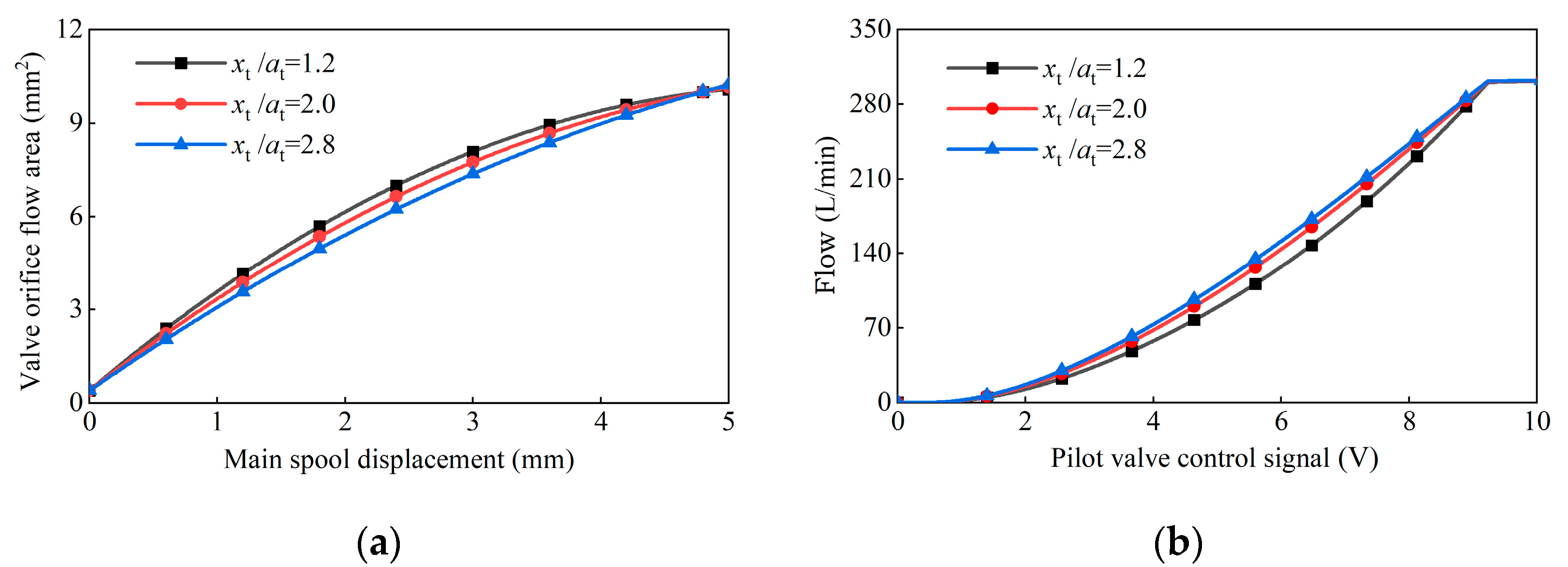
4.5.1. Trapezoidal Feedback Groove Parameters

To investigate the impact of trapezoidal feedback groove parameters on proportional valve flow characteristics, simulations are performed for three distinct ratios of groove height (xt) to initial area gradient (at). Key results are shown in Figure 9.
As shown in Figure 9a, all three trapezoidal feedback grooves maintain identical maximum flow areas. When groove height (xt) remains constant, a larger xt/at ratio results in reduced initial area gradient.
Figure 9b demonstrates that smaller xt/at ratios enhance micro-motion control performance but result in a steeper increase in flow gain with rising control signals. This indicates that reducing the xt/at ratio during valve design can achieve a gradual initial flow increase for smooth actuator startup without compromising maximum flow capacity.

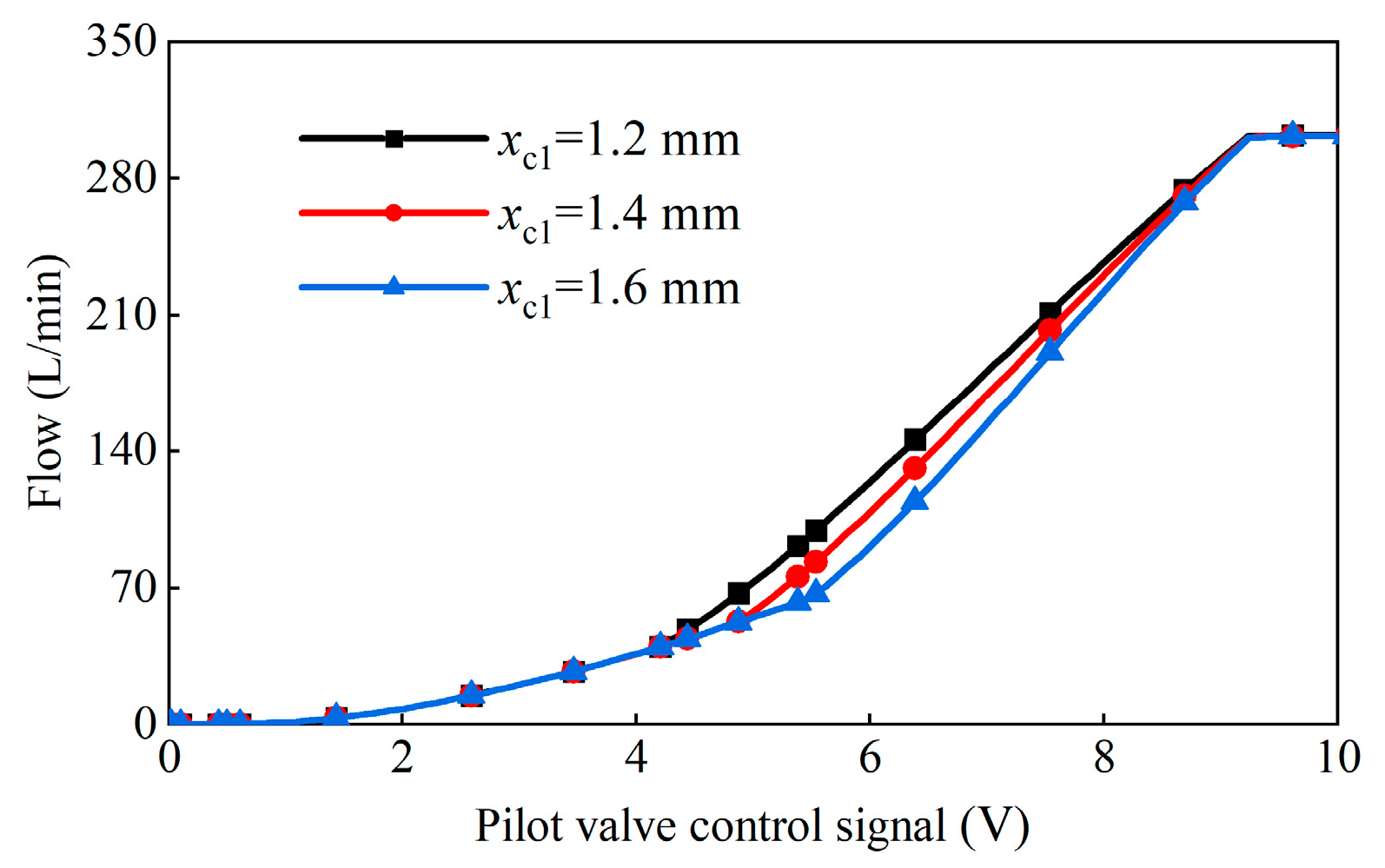
4.5.2. Composite Feedback Groove Parameters

As established in Section 4.5.1, increasing the initial area gradient (ac) of the feedback groove can reduce the main valve’s initial flow gain and improve micro-motion control performance. Building upon this, the influence of the transition point position (xc1) on the proportional valve characteristics is further investigated while keeping the ac constant. The results are shown in Figure 10.
The transition point positions for the composite feedback groove are set to 1.2 mm, 1.4 mm, and 1.6 mm, respectively. To ensure consistent maximum flow areas, larger xc1 values require smaller post-transition area gradients (bc).
Figure 10 reveals two key trends: (1) Increasing xc1 extends the micro-motion control region; (2) decreasing bc shortens the rapid actuation region. These findings indicate that xc1 can be optimized during valve design to tailor the relative durations of the micro-motion and rapid actuation phases according to specific equipment requirements.

5. Experiment

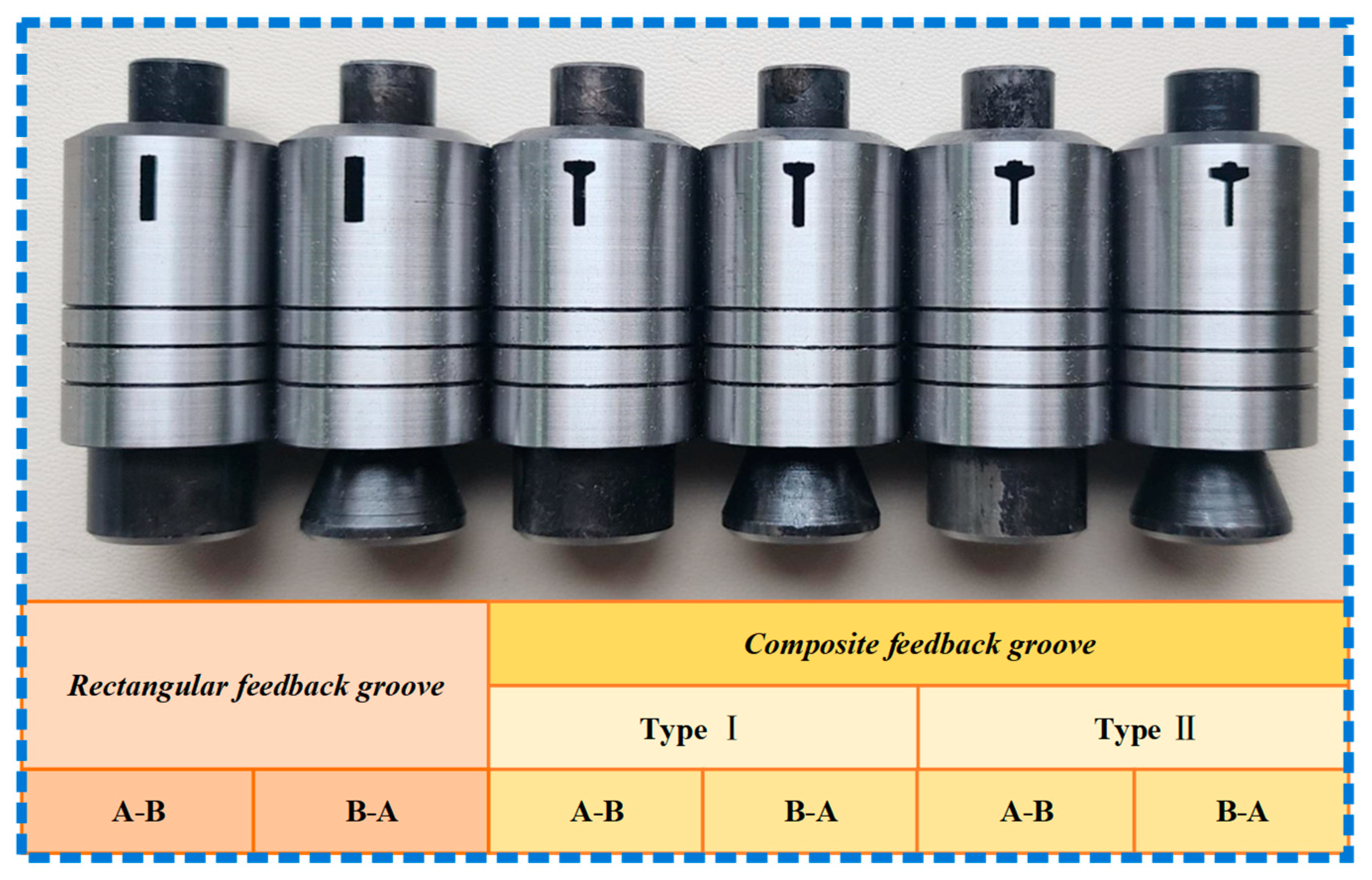
5.1. Developed Variable-Gain Feedback Groove Spools

As analyzed in Section 4, the composite-groove spool’s flow characteristics are divided into a micro-motion control region and a rapid actuation region, aligning well with the operating conditions of construction machinery such as excavators and cranes. Accordingly, as shown in Figure 11, this study developed three types feedback groove spools.
The three spool types differ only in feedback groove shape, with all other parameters being identical. Type one has a conventional rectangular feedback groove, type two a composite I groove, and type three a composite Ⅱ groove. Additionally, we designed two main spool configurations (Type A-B and Type B-A) with different inlet/outlet port arrangements to accommodate various installation requirements.
Figure 11 shows, from left to right, the following configurations: Type A-B spool with a rectangular feedback groove, Type B-A spool with a rectangular feedback groove, Type A-B spool with a composite I feedback groove, Type B-A spool with a composite I feedback groove, Type A-B spool with a composite Ⅱ feedback groove, Type B-A spool with a composite Ⅱ feedback groove. Composite I and II feedback grooves vary in dimensions, with detailed parameters shown in Figure 12.
The conventional rectangular feedback groove has an area gradient of 1.6 mm2/mm. For the composite I feedback groove, ac is 3.2 mm and bc is 1.2 mm. For the composite Ⅱ feedback groove, ac = 4.0 mm and bc = 0.8 mm. All three spool types have the same feedback groove pre-opening area of 0.8 mm2. However, the larger ac in the composite Ⅱ feedback groove requires a shorter pre-opening length (x0), increasing manufacturing difficulty. To address this, a 1.6 mm × 0.5 mm rectangular groove were designed as the pre-opening area for the composite Ⅱ groove. Moreover, to avoid experimental errors induced by machining, three replicate samples of each valve spool were fabricated. According to the machining report, the fit tolerance between the valve spool and sleeve is controlled within 10–12 μm, while the dimensional tolerance of the feedback groove is less than 0.05 mm.

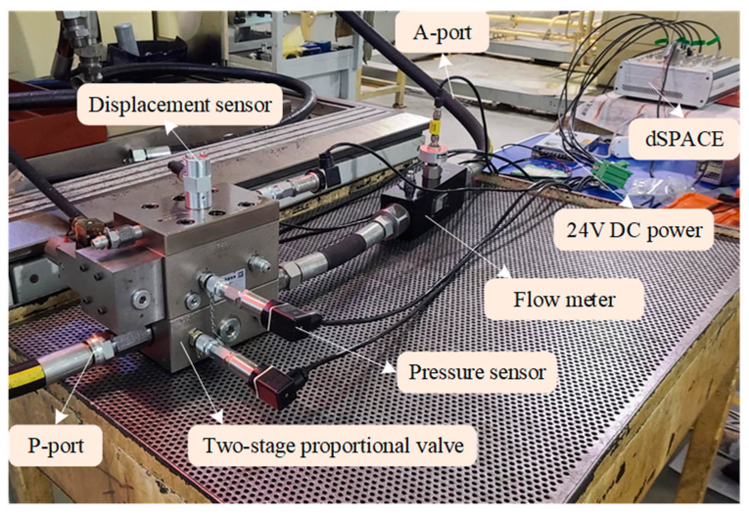
5.2. Experimental Platform Setup

Figure 13 presents the developed Valvistor valve (25 mm nominal size, 300 L/min rated flow, 35 MPa rated pressure) comprising two assemblies: the main valve and the pilot valve. The pilot valve includes a spool and a proportional solenoid, while the main valve comprises a main spool and a valve sleeve. To study the characteristics of the proportional valve with variable-gain feedback grooves and validate the Section 4 simulation results, a comparative experimental study was conducted using the three spool types.
Figure 14 illustrates the experimental setup. The inlet (P) and outlet (A) ports of the two-stage proportional valve connect to the corresponding test bench pipelines. The test bench is equipped with a cooling system and temperature sensors. Given that hydraulic oil temperature significantly affects both fluid viscosity and the flow coefficient of the valve orifice, the oil temperature is maintained at 40–45 °C throughout the experiments. Three pressure sensors monitor the pressures at P and A and in the main valve’s control chamber. A displacement sensor, connected to the main spool via a threaded joint, measures its displacement. The pilot valve’s proportional solenoid has an integrated displacement sensor for pilot spool displacement detection. Both displacement and pressure signals are transmitted to the dSPACE and then to the computer. Computer-generated command signals are sent through the dSPACE and amplifiers to the proportional solenoids. Table 1 lists the technical specifications of the experimental devices and sensors.

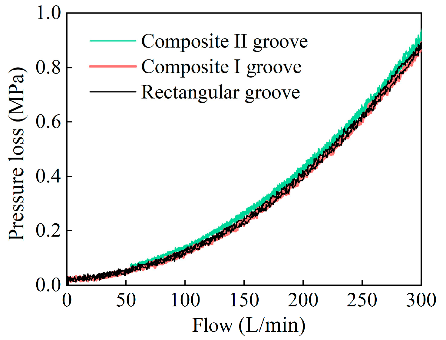
5.3. Pressure Loss Characteristics

Hydraulic oil was supplied to port P of the test valve, with the flow progressively increased to 300 L/min. During this process, the pressures at ports P and A were recorded, and the resulting pressure loss characteristic curve is presented in Figure 15. The pressure loss of the two-stage proportional valve was measured to be 0.88 MPa. This relatively low pressure loss indicates low energy consumption. Notably, the main valve orifices of all three spool types have identical flow areas, leading to comparable pressure losses across the proportional valves, regardless of the feedback groove shape. This finding confirms that the variable-gain feedback groove does not increase the overall valve pressure loss.

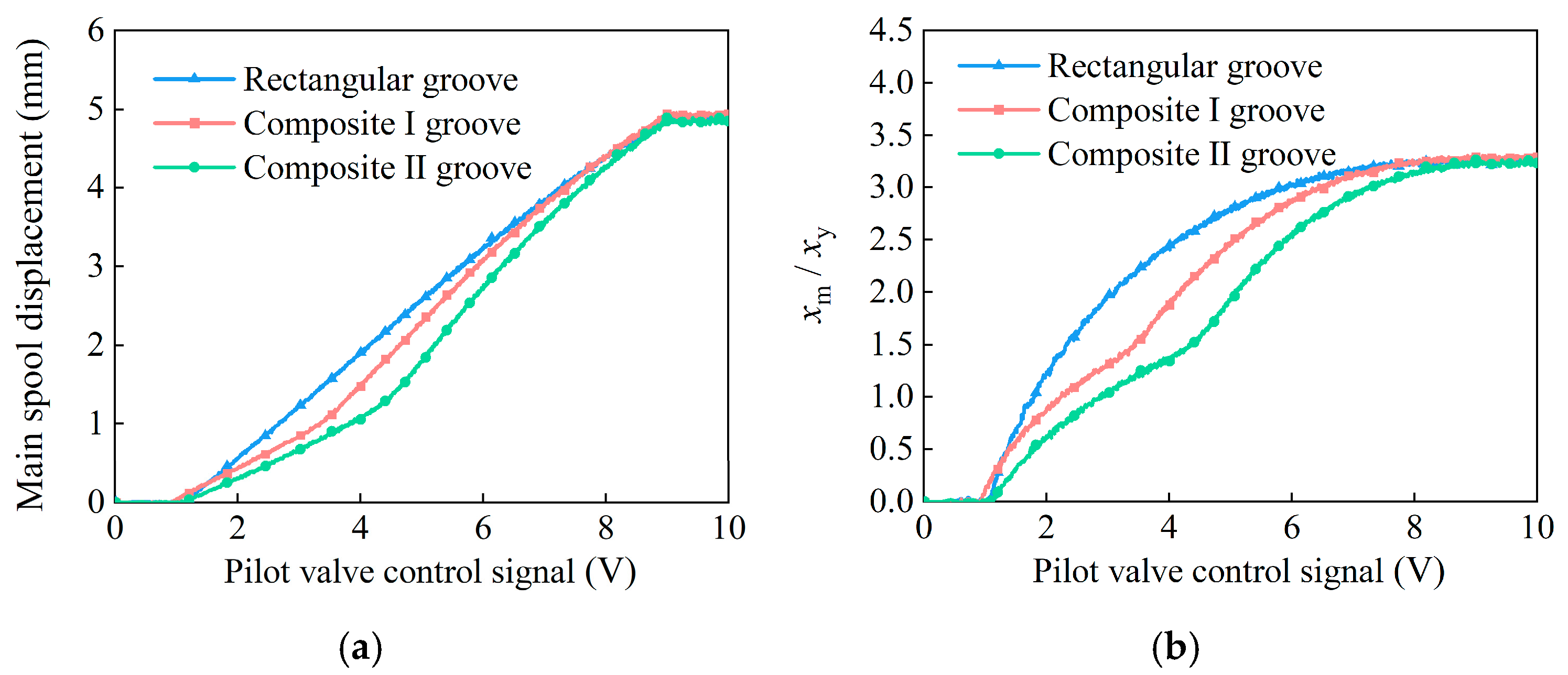
5.4. Experimental Study on Main Spool Displacement Characteristics

A ramp control signal of 0–10 V was applied to the pilot valve. The displacement control characteristics of the main spool are shown in Figure 16. Specifically, Figure 16a illustrates the main spool displacement characteristics for the three feedback groove shapes, and Figure 16b depicts the spool displacement amplification relationship. This relationship is defined as the ratio of the main spool displacement (xm) to the pilot spool displacement (xy).
As shown in Figure 16a, the experimental results align with the simulation predictions. Due to the pilot valve dead zone and feedback groove pre-opening effects, the main spool displacement exhibits a dead zone with an effective control range of 1.1–8.9 V. Since the two-stage valve developed in this study primarily targets construction machinery such as excavators, the actual working conditions and application scenarios of such equipment impose relatively lenient requirements on control accuracy and dynamic response. Consequently, the dead zone effect is deemed acceptable in engineering practice. The experimental results demonstrate that the dynamic response time of the main spool in this two-stage valve is less than 50 ms, significantly outperforming conventional multi-way valves. Moreover, its dead zone is also smaller than that of conventional multi-way valves. With a rectangular feedback groove, the main spool displacement and control signal are roughly linearly related. For composite feedback grooves, the displacement characteristic has a micro-motion region and a rapid actuation region.
Figure 16b highlights that the feedback groove shape dictates the displacement mapping between the pilot and main spools. At a 3 V control signal, the rectangular-groove valve reaches an amplification factor of 1.98. For the composite-I-groove valve, the factor is 1.31, and for the composite-II-groove valve, it is 1.05. This demonstrates that larger ac values reduce displacement gain, enhancing micro-motion control. Consistently, under identical control signals, main spool displacement is ranked as follows: rectangular-groove valve > composite-I-groove valve > composite-II-groove valve.
Additionally, the composite-groove valves have displacement amplification factors with a clear transition point. Specifically, the composite-II-groove valve shows a transition at approximately 4.4 V, while the composite-I-groove valve transitions at 3.5 V. As illustrated in Figure 12, the xc1 value for the composite II feedback groove measures 1 mm, exceeding that of the composite Ⅰ feedback groove (only 0.75 mm). These results directly validate the accuracy of the simulation in Section 4.5.2, confirming that larger xc1 values in composite feedback grooves extend the micro-motion control region.

5.5. Experimental Study on Flow Characteristics

Figure 17a compares the flow characteristics of the main spool across the three feedback groove geometries. Since pilot flow cannot be directly measured, flow amplification factors are not calculated. Instead, main valve flow gain (Figure 17b) is adopted to evaluate variable-gain feedback groove performance.
Flow gain is defined as the flow change per 0.1 V control voltage increment. Crucially, (1) lower flow gain indicates finer flow control resolution, and (2) higher flow gain reflects greater control sensitivity and enhanced dynamic response. Figure 17a,b demonstrate that composite-groove valves achieve lower flow gains and superior micro-motion control compared to conventional rectangular-groove valves. Their flow curves are segmented into micro-motion control regions and rapid actuation regions.
Region lengths and flow gains vary with composite groove dimensions:
  • Composite I feedback groove: Micro-motion: 1.1–3.5 V; rapid actuation: 3.5–8.9 V.
  • Composite II feedback groove: Micro-motion: 1.1–4.4 V; rapid actuation: 4.4–8.9 V.
Within the micro-motion region: The flow gain of the conventional rectangular-groove valve is approximately 2.2 times that of the composite-I-groove valve and 2.6 times that of the composite-II-groove valve. (At a control signal of 3 V, the measured flow gains are 5.36 L/min/0.1 V, 2.41 L/min/0.1 V, and 2.04 L/min/0.1 V for the rectangular-, composite-I-, and composite-II-groove valves, respectively). The composite-II-groove valve demonstrates the longest micro-motion region, the smallest flow gain, and consequently the best micro-motion control performance.
Within the rapid actuation region: The flow gains of the composite feedback groove valves exceed that of the conventional rectangular-groove valve. Due to its smaller bc value (post-transition area gradient), the composite-II-groove valve exhibits the largest flow gain in this region.
In conclusion, the shape and parameters of the feedback groove directly determine the flow characteristics of the main valve. By designing variable-gain feedback grooves tailored to specific application requirements, the flow gain of the main valve can be effectively regulated.

6. Discussion

6.1. Uncertainty Evaluation

The evaluation of measurement uncertainty includes Class A uncertainty evaluation and Class B uncertainty evaluation [46]. Class A uncertainty refers to the uncertainty associated with the measurement results. This study evaluates the measurement uncertainty through flow characteristics tests and displacement characteristics tests. The uncertainty components are quantified as follows:
Class A Uncertainty:
u A = 0.223 \ %
Class B uncertainty originates from measurement devices, including uncertainties in pressure (p), spool displacement (x), and flow (q).
Class B Uncertainty:
u B = u ( p ) 2 + u ( x ) 2 + u ( q ) 2 = 0.101 \ %
Combined Experimental Uncertainty:
u S = u A 2 + u B 2 = 0.245 \ %
The overall uncertainty us = 0.245\%, which meets the requirement of being less than 0.5\%.

6.2. Benchmarking Against Commercially Available Products

A comparative analysis was conducted between EATON’s commercially available NG25 displacement–hydraulic feedback two-stage proportional valve and the proposed variable-gain feedback groove valve, with key performance metrics summarized in Table 2. Critical observations reveal that while the NG25 possesses a higher-rated flow capacity and lower pressure loss, it lacks segmented flow regulation capability. In contrast, under identical pilot valve control conditions, the developed variable-gain feedback groove valve exhibits a flow gain of 2.04 L/(min·0.1 V) in the micro-motion range. This value is significantly smaller than the 8.54 L/(min·0.1 V) observed in the EATON NG25, indicating markedly improved micro-motion control characteristics. Furthermore, the developed valve demonstrates superior dynamic response characteristics and features segmented flow regulation capability.

7. Conclusions

Conventional methods for regulating flow characteristics in two-stage proportional valves face significant limitations: they depend on complex throttling notch designs in the main spool and neglect analysis of the pilot–main valve mapping relationship. To overcome these constraints, this study proposes a novel flow characteristic regulation method based on variable-gain feedback grooves. This approach achieves flow characteristic regulation without modifying the main spool throttling notch or requiring additional auxiliary equipment. Crucially, it preserves the valve’s inherent high dynamic response and robust flow capacity. Leveraging this method, we optimized the flow characteristics of displacement–hydraulic feedback two-stage proportional valves and expanded their engineering applicability. Through mechanistic modeling, spool design, simulation, and experimental validation, the following conclusions are drawn:
(1)
Mathematical modeling reveals the core mechanism: variable-gain feedback grooves dynamically adjust the pilot-to-main valve mapping relationship. By modifying groove geometry and area gain characteristics, spool displacement mapping is reconfigured to achieve target signal-flow characteristic curves.
(2)
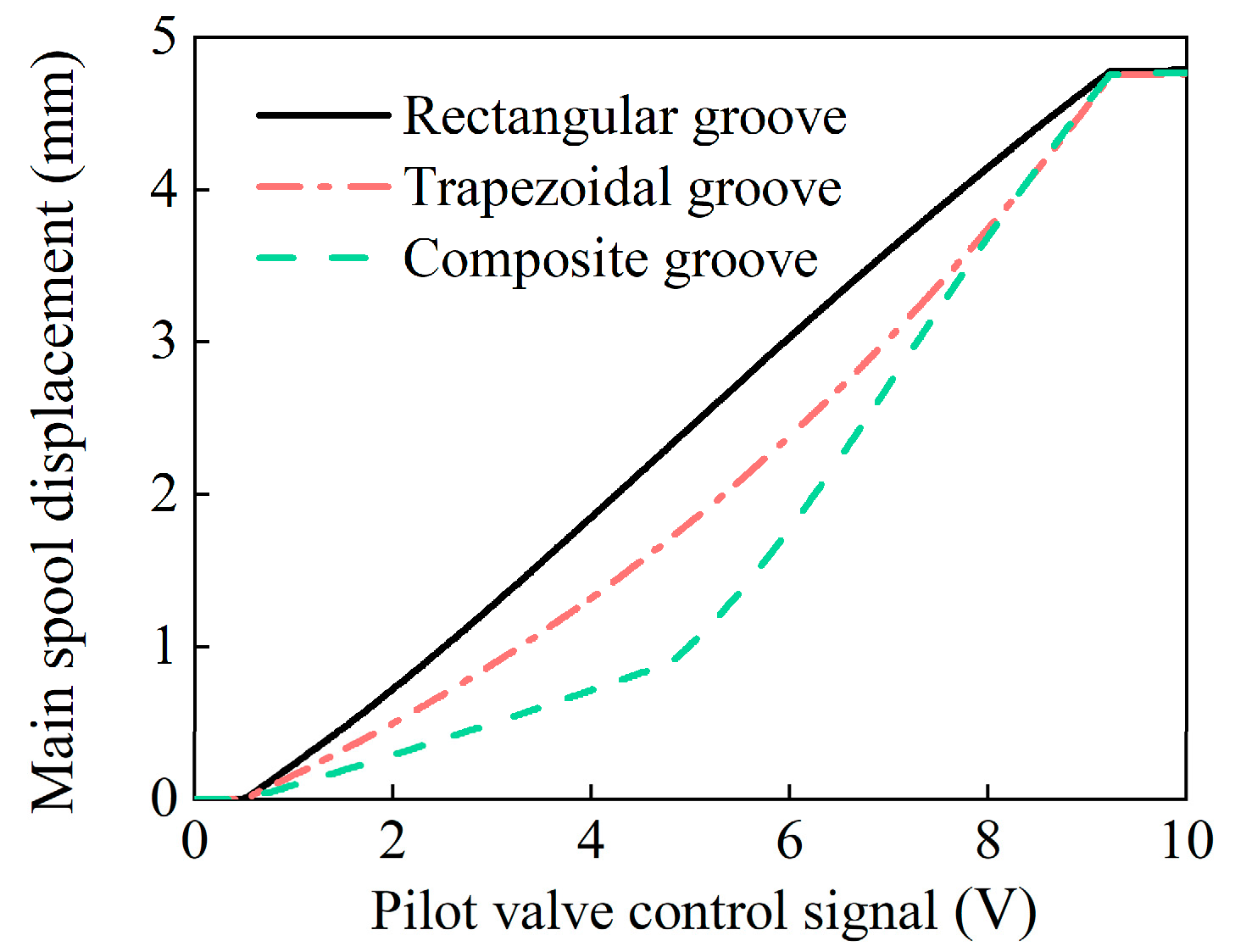
Two groove profiles are designed: trapezoidal and composite. Simulations show that conventional rectangular grooves produce near-linear flow rate vs. signal relationships; trapezoidal grooves exhibit monotonically increasing flow rate gain; composite grooves generate dual-regime curves with distinct linear regions before/after transition points. Moreover, larger feedback groove area gains improve main spool response speed.
(3)
Prototypes with composite grooves are developed for construction machinery applications. Experiments confirm that the feedback groove effectively regulates flow characteristics. The pilot–main mapping relationship is inversely proportional to the groove area gain: higher gain enhances micro-motion control for minute flows; lower gain increases main valve flow gain, enabling rapid actuation.
(4)
Comparative experiments show the composite-groove spool achieves segmented flow characteristics (micro-motion and rapid actuation regions). Its flow gain in the micro-motion region (2.04 L/(min·0.1 V)) is 61.9% lower than that of conventional rectangular grooves, effectively improving micro-motion performance.
(5)
Parametric studies confirm that adjusting the groove’s area gain and transition point flexibly tunes flow gain magnitude and micro-motion region length. Additionally, the variable-gain feedback groove method does not significantly increase the valve’s pressure loss or energy consumption; the pressure loss of the developed two-stage proportional valve is only 0.88 MPa (at 300 L/min rated flow).
Limitations: While this study introduces a novel paradigm for flow regulation by focusing on pilot–main valve mapping relationships, its core principle inherently restricts applicability to displacement–hydraulic feedback proportional valves. The proposed method is currently incompatible with displacement–electric or displacement–force feedback valve architectures.
Future Work: Subsequent research will focus on field validation of variable-gain feedback groove valves in construction machinery (e.g., excavators) to quantify their impact on system-level energy efficiency and handling precision. Future work will also expand feedback groove topologies beyond trapezoidal/composite designs and develop AI/neural-network-driven intelligent co-optimization methods for groove geometry.

Author Contributions

Conceptualization, X.Z., L.Q. and L.G.; methodology, X.Z. and H.G.; software, X.Z. and H.G.; validation, C.X. and B.W.; formal analysis, X.Z. and B.W.; resources, L.Q.; writing—original draft preparation, X.Z.; writing—review and editing, X.Z. and L.Q.; supervision, L.Q. and L.G.; project administration, L.Q. and L.G. All authors have read and agreed to the published version of the manuscript.

Funding

This research was funded by the National Key Research and Development Program of China (No. 2022YFB3403001) and supported by Natural Science Foundation of China (No. 52275063).

Data Availability Statement

The data that support the findings of this study are available from the corresponding author upon reasonable request.

Conflicts of Interest

The authors declare no conflicts of interest.

References

  1. Jiao, Z.; Wu, S.; Li, Y.; Zhang, C.; Jin, H.; Shu, S.; Wei, R.; Li, R.; Wang, Y.; Zhang, H. Development Status and Trends of the Intelligence of Hydraulic Components and Systems. J. Mech. Eng. 2023, 59, 357–384. [Google Scholar]
  2. Zhong, Q.; Wang, J.; Xu, E.; Yu, C.; Li, Y. Multi-objective optimization of a high speed on/off valve for dynamic performance improvement and volume minimization. Chin. J. Aeronaut. 2024, 37, 435–444. [Google Scholar] [CrossRef]
  3. Tamburrano, P.; Plummer, A.; Distaso, E.; Amirante, R. A review of direct drive proportional electrohydraulic spool valves: Industrial state-of-the-art and research advancements. J. Dyn. Syst. Meas. Control 2019, 141, 020801. [Google Scholar] [CrossRef]
  4. Li, Y.; Li, R.; Yang, J.; Yu, X.; Xu, J. Review of Recent Advances in the Drive Method of Hydraulic Control Valve. Processes 2023, 11, 2537. [Google Scholar] [CrossRef]
  5. Xie, H.; Wang, C.; Yang, H. Research on back-pressure compensation characteristics of a pilot-assisted load control valve applied in overrunning load hydraulic systems. Flow Meas. Instrum. 2021, 82, 102048. [Google Scholar] [CrossRef]
  6. Suzuki, K.; Urata, E. Development of a water hydraulic pressure-compensated flow control valve. Int. J. Fluid Power 2008, 9, 25–33. [Google Scholar] [CrossRef]
  7. Park, Y.; Kim, B.; Jeon, J.; Jung, D.; Choi, S. The Effect of Spool Displacement Control to the Flow Rate in the Piezoelectric Stack-Based Valve System Subjected to High Operating Temperature. Actuators 2021, 10, 239. [Google Scholar] [CrossRef]
  8. Liu, J.; Sitte, A.; Weber, J. Investigation of temperature influence on flow mapping of electrohydraulic valves and corresponding application. Fluid Power Syst. Technol. ASME 2022, 86335, V001T01A022. [Google Scholar]
  9. Liu, H.; Quan, L.; Zhao, X.; Ge, L.; Xia, L. Research on Displacement and Flow Control Characteristics of the Proportional Directional Valve Based on a Flow Feedback Mechanism. IEEE/ASME Trans. Mechatron. 2025. [Google Scholar] [CrossRef]
  10. Zhao, R.; Chai, W.; Zhang, Y.; Yuan, X.; Lian, Z.; Shi, H. Dynamics and experimental study of a novel proportional directional valve with displacement feedback groove controlled by high-speed switching valves. Flow Meas. Instrum. 2024, 100, 102711. [Google Scholar] [CrossRef]
  11. Huang, J.; Wang, X.; Wang, H.; Hao, H. Development of a flow control valve with digital flow compensator. Flow. Meas. Instrum. 2019, 66, 157–169. [Google Scholar] [CrossRef]
  12. Hao, Y.; Quan, L.; Huang, J. Research on the performance of electro-hydraulic proportional flow valve controlled by active pilot pump. Proc. Inst. Mech. Eng. E J. Process Mech. Eng. 2017, 231, 720–731. [Google Scholar] [CrossRef]
  13. Xu, B.; Shen, J.; Liu, S.; Qi, S.; Zhang, J. Research and development of electro-hydraulic control valves oriented to industry 4.0: A review. Chin. J. Mech. Eng. 2020, 33, 1–20. [Google Scholar] [CrossRef]
  14. Ding, R.; Yan, P.; Cheng, M.; Xu, B. A flow inferential measurement of the independent metering multi-way valve based on an improved RBF neural network. Measurement 2023, 223, 113750. [Google Scholar] [CrossRef]
  15. Lu, L.; Yao, B. Energy-saving adaptive robust control of a hydraulic manipulator using five cartridge valves with an accumulator. IEEE Trans. Ind. Electron. 2014, 61, 7046–7054. [Google Scholar] [CrossRef]
  16. Muniak, D. Sizing the radiator control valve taking account of inner authority. Procedia Eng. 2016, 157, 98–105. [Google Scholar] [CrossRef]
  17. Hucko, S.; Krampe, H.; Schmitz, K. Evaluation of a soft sensor concept for indirect flow rate estimation in solenoid-operated spool valves. Actuators 2023, 12, 148. [Google Scholar] [CrossRef]
  18. Jian, H.; Du, M.; Gu, H. Modeling and bifurcation analysis of a hydraulic actuator system with different valve spool geometry. Adv. Mech. Eng. 2022, 14, 16878132221118439. [Google Scholar] [CrossRef]
  19. Ye, Y.; Yin, C.; Li, X.; Zhou, W.; Yuan, F. Effects of groove shape of notch on the flow characteristics of spool valve. Energy Convers. Manag. 2014, 86, 1091–1101. [Google Scholar] [CrossRef]
  20. Ye, Y.; Yin, C.; Liu, H.; Zou, G.; Jiang, X. Stationary Flow Characteristics of Notches on Throttling Grooves. Trans. Chin. Soc. Agric. Mach. 2014, 45, 308–316. [Google Scholar]
  21. Pan, X.; Wang, G.; Lu, Z. Flow field simulation and a flow model of servo-valve spool valve orifice. Energy Convers. Manag. 2011, 52, 3249–3256. [Google Scholar] [CrossRef]
  22. Zhang, X.; Wang, A.; Chen, W.; Kuang, L.; Jiang, T. Methodology for expressing the flow coefficients of coupled throttling grooves in a proportional—Directional valve. J. Zhejiang Univ.-Sci. A 2020, 21, 799–816. [Google Scholar] [CrossRef]
  23. Muniak, D. Control valve with a constant inner authority value. J. Therm. Sci. 2018, 27, 487–495. [Google Scholar] [CrossRef]
  24. Muniak, D. A new methodology to determine the pre-setting of the control valve in a heating installation. Appl. Energy 2014, 135, 35–42. [Google Scholar] [CrossRef]
  25. Borghi, M.; Milani, M.; Paoluzzi, R. Influence of Notch Shape and Number of Notches on the Metering Characteristics of Hydraulic Spool Valves. Int. J. Fluid Power 2005, 6, 5–18. [Google Scholar] [CrossRef]
  26. Li, S.; Du, J.; Shi, Z.; Xu, K.; Shi, W. Characteristics Analysis of the Pilot-Operated Proportional Directional Valve by Experimental and Numerical Investigation. Energies 2022, 15, 9418. [Google Scholar] [CrossRef]
  27. Qian, J.; Hou, C.; Mu, J.; Gao, Z.; Jin, Z. Valve core shapes analysis on flux through control valves innuclear power plants. Nucl. Eng. Technol. 2020, 52, 2173–2182. [Google Scholar] [CrossRef]
  28. Yuan, S.; Yin, C.; Ye, Y.; Liu, S. Studies on the Throttling Performance of Non-circumferential Throttling Port. Trans. Chin. Soc. Agric. Mach. 2014, 45, 321–327. [Google Scholar]
  29. Kong, X.; Song, Y.; Ai, C.; Hu, J.; Xia, Q. Visualization Experiment of Flow Characteristics of Special Shaped Valve Port in Proportional Valve Using PIV Technology. Trans. Chin. Soc. Agric. Mach. 2015, 46, 328–335. [Google Scholar]
  30. Qiu, T.; Yang, L.; Zhang, J.; Wang, Z.; Song, Y.; Ai, C. Investigation of Valve Seat Cone Angle on Small Opening Direct-Acting Relief Valve Cavitation Noise. Machines 2024, 12, 434. [Google Scholar] [CrossRef]
  31. Ji, H.; Fu, X.; Yang, H. Study on steady flow force of non-circular opening spool valve. J. Mech. Eng. 2003, 6, 13–17. [Google Scholar] [CrossRef]
  32. Simic, M.; Herakovic, N. Reduction of the flow forces in a small hydraulic seat valve as alternative approach to improve the valve characteristics. Energy Convers. Manag. 2015, 89, 708–718. [Google Scholar] [CrossRef]
  33. Shangguan, S.; Duan, H.; Li, R.; Yuan, W.; Chen, L.; Wang, Z.; Chen, H. Study on the flow field and steady-state hydrodynamics of a sliding valve with a sloping U-shaped throttle groove. Flow Meas. Instrum. 2025, 104, 102886. [Google Scholar] [CrossRef]
  34. Yuan, C.; Zhu, L.; Du, Z.; Liu, S. Numerical investigation into the cavitating jet inside water poppet valves with varied valve seat structures. Eng. Appl. Comput. Fluid Mech. 2021, 15, 391–412. [Google Scholar] [CrossRef]
  35. Frosina, E.; Marinaro, G.; Amoresano, A.; Senatore, A. A numerical and experimental methodology to characterize the gaseous cavitation in spool valves with U-notches. J. Fluids Eng. 2021, 143, 101401. [Google Scholar] [CrossRef]
  36. Zou, J.; Fu, X.; Du, X.; Ruan, X.; Ji, H.; Ryu, S.; Ochiai, M. Cavitation in a non-circular opening spool valve with U-grooves. Proc. Instn. Mech. Eng. A J. Power Energy 2008, 222, 413–420. [Google Scholar] [CrossRef]
  37. Jia, W.; Liu, Y.; Yin, C.; Li, G.; Zhu, D.; Ding, S. Effects of U-shaped two-step throttling groove parameters on cavitation erosion characteristics. J. Theor. Appl. Mech. 2021, 59, 529–538. [Google Scholar] [CrossRef]
  38. Du, X.; Fu, X.; Tang, H. Effects of Gas nucleus on Cavitation Inception and Bubble characteristics inside V-throttling groove. Adv. Mater. Res. 2014, 1006, 147–151. [Google Scholar] [CrossRef]
  39. Li, Y.; Bai, Y.; Zhang, J.; Jiang, J. Flow Field Simulation and Experimental Research on the Triangle Groove Cone Throttle Valve. Appl. Mech. Mater. 2015, 779, 42–49. [Google Scholar] [CrossRef]
  40. Zhao, X.; Wang, B.; Quan, L.; Ge, L.; Zou, X. Design and Characteristics of Independent Metering Control Multi-way Valve with Spool in Series. J. Mech. Eng. 2024, 60, 113–125. [Google Scholar]
  41. Zhao, X.; Wang, B.; Zhao, B.; Li, Y.; Quan, L. Research on characteristics of differential pressure controllable multi-way valve driven by electro-mechanical actuator. Mach. Tool Hydraul. 2022, 50, 73–78. [Google Scholar]
  42. Wang, B.; Zhao, X.; Quan, L.; Li, Y.; Hao, Y.; Ge, L. A method for improving flow control valve performance based on active differential pressure regulation. Measurement 2023, 219, 113271. [Google Scholar] [CrossRef]
  43. Stosiak, M.; Karpenko, M.; Skačkauskas, P.; Deptuła, A. Identification of pressure pulsation spectrum in a hydraulic system with a vibrating proportional valve. J. Vib. Control 2024, 30, 4917–4930. [Google Scholar] [CrossRef]
  44. Stosiak, M.; Skačkauskas, P.; Towarnicki, K.; Deptuła, A.; Deptuła, A.; Praznowski, K.; Grzywacz, Z.; Karpenko, M.; Urbanowicz, K.; Lapka, M. Analysis of the impact of vibrations on a micro-hydraulic valve using a modified induction algorithm. Machines 2023, 11, 184. [Google Scholar] [CrossRef]
  45. Lu, L.; Wang, J.; Li, M.; Ryu, S. Experimental and numerical analysis on vortex cavitation morphological characteristics in u-shape notch spool valve and the vortex cavitation coupled choked flow conditions. Int. J. Heat Mass Transf. 2022, 189, 122707. [Google Scholar] [CrossRef]
  46. Liu, H.; Geng, H.; Yang, G.; Huang, W.; Wang, X.; Quan, L. Research on flow measurement and control integrated strategy based on a flow sensor with active regulation. Measurement 2025, 249, 117055. [Google Scholar] [CrossRef]
Figure 1. Comparison of flow characteristic regulation methods for two-stage proportional valves.
Machines 13 00648 g001
Figure 2. Schematic of a two-stage proportional valve.
Machines 13 00648 g002
Figure 3. Design of variable-gain feedback grooves.
Machines 13 00648 g003
Figure 4. Co-simulation model.
Machines 13 00648 g004
Figure 5. CFD simulations.
Machines 13 00648 g005
Figure 6. Main spool displacement curves for different feedback groove shapes.
Machines 13 00648 g006
Figure 7. Flow characteristics of valves with different feedback groove shapes. (a) Pilot and main valve flow. (b) Flow amplification factor.
Machines 13 00648 g007
Figure 8. Dynamic characteristics of the main spool for different feedback groove shapes.
Machines 13 00648 g008
Figure 9. Influence of trapezoidal feedback groove parameters on flow characteristics. (a) Feedback groove flow area curve. (b) Proportional valve flow characteristics.
Machines 13 00648 g009
Figure 10. Influence of composite feedback groove parameters on flow characteristics.
Machines 13 00648 g010
Figure 11. Developed variable-gain feedback groove spools.
Machines 13 00648 g011
Figure 12. Dimensions of variable-gain feedback grooves.
Machines 13 00648 g012
Figure 13. Developed two-stage proportional valve.
Machines 13 00648 g013
Figure 14. Experimental setup.
Machines 13 00648 g014
Figure 15. Experimental pressure loss characteristic curve.
Machines 13 00648 g015
Figure 16. Experimental displacement characteristics of variable-gain feedback groove spools. (a) Spool displacement. (b) Displacement amplification factor.
Machines 13 00648 g016
Figure 17. Experimental flow characteristics. (a) Valve flow. (b) Flow gain.
Machines 13 00648 g017
Table 1. Detailed information of some devices.
ElementSupplier/ModleSpecification
Flow meterParker (Mineral Wells, TX, USA)/SCFT 300Range: 8–300 L/min; Accuracy: ±1% FS
Pressure sensorParker/SCP01Range: 0–40 MPa; Accuracy: ±0.2% FS
LVDTSchramme (Hamburg, Germany)Range: ±5 mm; Accuracy: ±0.25% FS
Proportional solenoidSchramme/GP8045A59Rated force: 85 N; Working stroke: 3 mm
Table 2. Comparative performance.
PerformanceEATON NG25Valve from
This Paper
Pressure loss (rated flow)9 bar (400 L/min)8.8 bar (300 L/min)
Step response time85 ms50 ms
Feedback groove profileRectangularComposite
Segmented controlNot SupportedEnabled
Flow resolution under
consistent pilot conditions
8.54 L/(min·0.1 V)2.04 L/(min·0.1 V)
Disclaimer/Publisher’s Note: The statements, opinions and data contained in all publications are solely those of the individual author(s) and contributor(s) and not of MDPI and/or the editor(s). MDPI and/or the editor(s) disclaim responsibility for any injury to people or property resulting from any ideas, methods, instructions or products referred to in the content.

