1. Introduction
Agricultural labor comprises heavy and repetitive tasks, such as carrying crates of produce or hoeing the soil. These tasks cause frequent muscular injuries and fatigue on the worker [
1]. Moreover, the escalating shortage of agricultural labor [
2] increases the amount of work each available farmer needs to perform, which consequently increases fatigue and other long-term musculoskeletal injuries [
3]. Devices such as electric shears assist the farmer by greatly reducing the effort required to cut branches or leaves. However, these kinds of tools are limited to specific tasks. An exoskeleton can assist the farmer (or a different kind of worker) with heavy and/or repetitive tasks as it assists the user with joint movement [
4], increasing productivity and reducing the likelihood of injury.
Given this context, the main goal of this review is to analyze recent developments in upper-limb exoskeletons as a preparatory step toward designing a prototype for use in agricultural environments. Although exoskeletons specifically designed for agriculture are limited in number, these devices are highly versatile and can be adapted to different use cases, provided they meet the biomechanical and ergonomic requirements of the application. Therefore, this review does not restrict itself to agricultural exoskeletons but instead focuses on identifying and categorizing existing upper-limb exoskeletons—both assistive and rehabilitative—that offer valuable insights into human–machine interaction strategies, actuation methods, control systems, sensor integration, and mechanical configurations. By extracting and comparing these key specifications, this study aims to provide a solid technical foundation for the development of a functional and effective prototype tailored to the physical demands of agricultural labor.
This work offers a structured and comparative overview of assistive and rehabilitation exoskeletons specifically targeting the upper limb, consolidating key information such as Degrees of Freedom, actuation types, sensors used as control inputs, weight, and mobility in a concise set of tables. Unlike broader reviews, this work emphasizes practical parameters that directly impact usability, such as weight. This approach allows readers—particularly designers and engineers—to quickly assess and compare design trends and trade-offs across multiple devices, thus supporting more informed design decisions.
2. Methodology
This section describes the research methodology, including the databases used and the search strategies implemented to gather relevant information, focusing on the development of upper-limb exoskeletons. Trends in the field are also highlighted to support the study’s objectives.
The information used to develop this section was taken from the following databases: SageJournals, Frontiers, Springer Link, ASME, IEEE Xplore, and ScienceDirect.
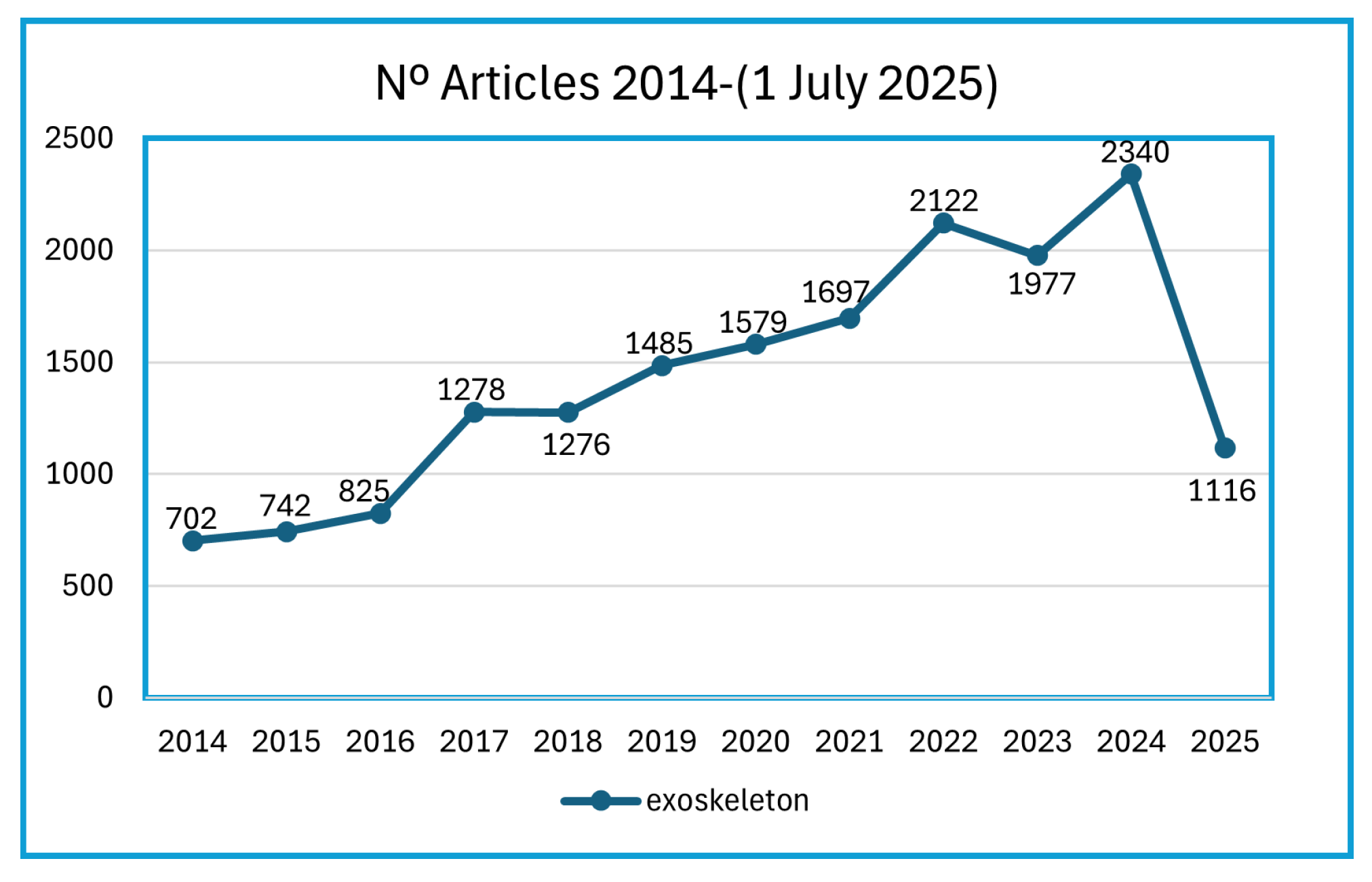
Searching the Scopus database with the keywords exoskeleton, upper-limb exoskeleton (upper and limb and exoskeleton), and lower-limb exoskeleton (lower and limb and exoskeleton) returns the number of documents published over 10 years.
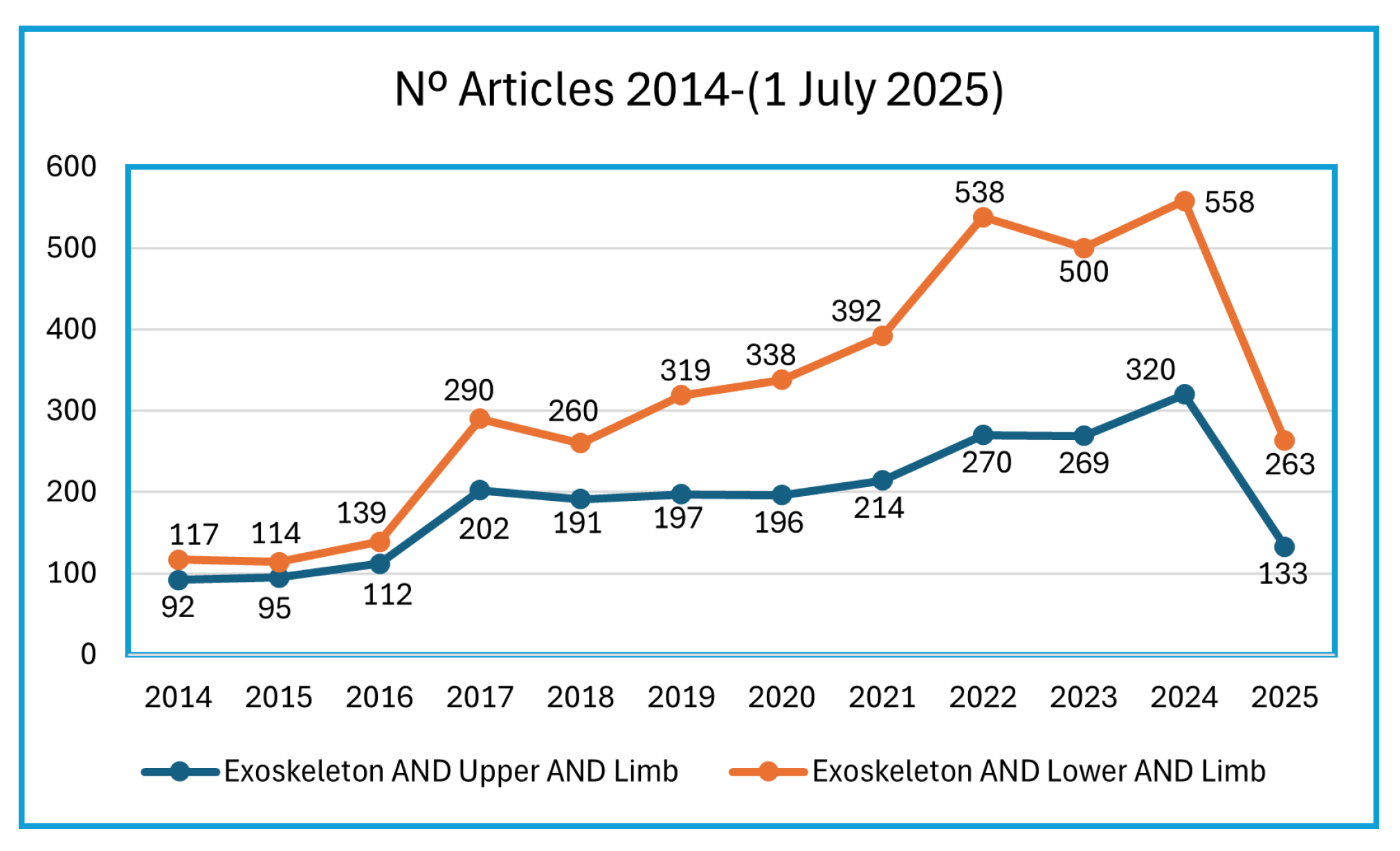
Figure 1 shows that there has been a great increase in interest in exoskeleton research. Furthermore, it can also be seen in
Figure 2 that the research interest in lower-limb exoskeletons is greater than in upper-limb exoskeletons.
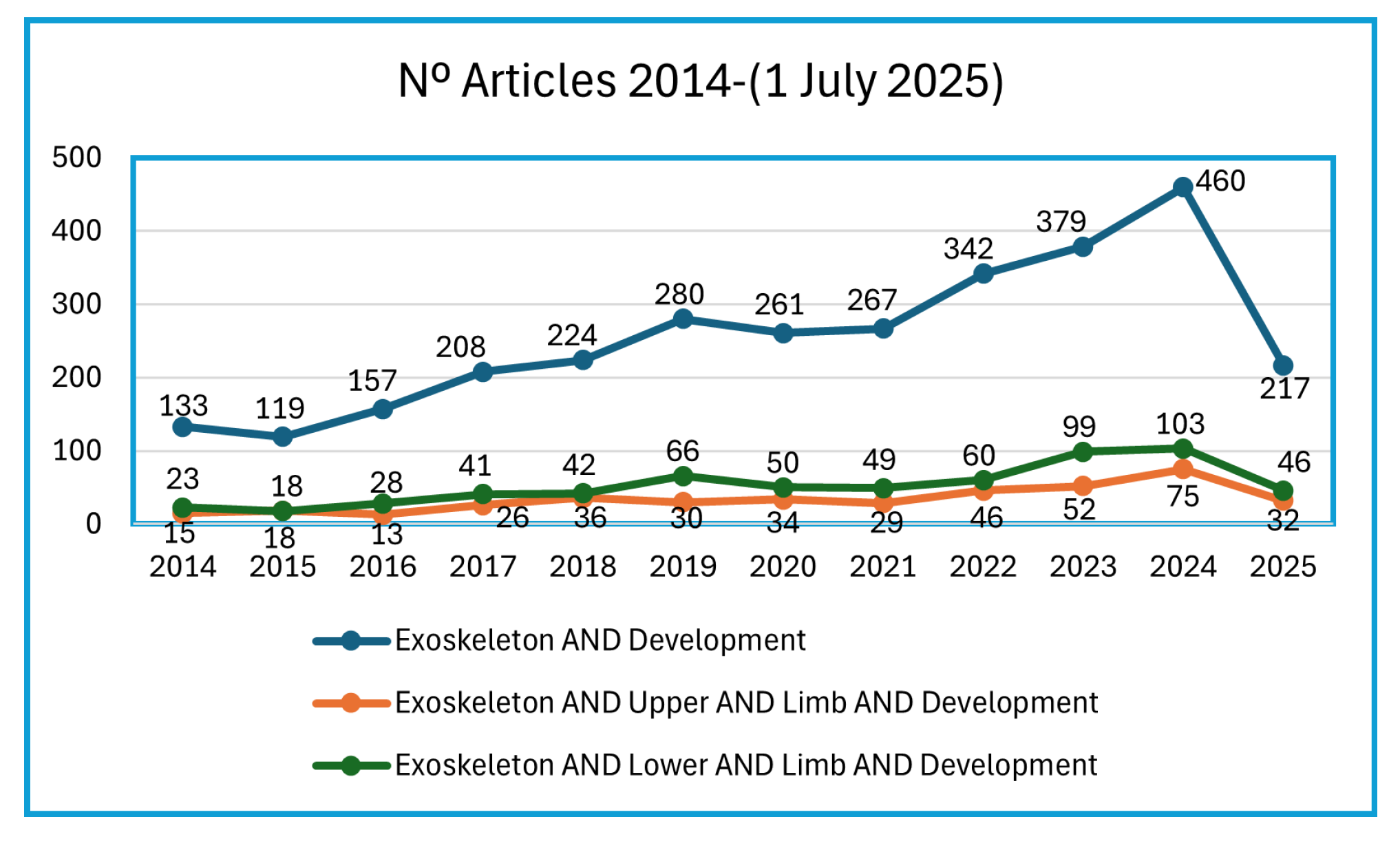
Although the searched documents are related to exoskeleton control, only a few focus on the development of the exoskeleton, which is the focus of this work.
To make the number of articles more precise, the keyword “development” was added to the search and the number of documents falls considerably, but has continued to grow steadily over the years, as shown in the graph in
Figure 3.
As previously stated, the objective of this review is to establish a foundation for the development of an exoskeleton aimed at agricultural applications. Although the figures show that many papers have been published on upper-limb exoskeletons, only those that meet certain criteria were included. Specifically, papers were excluded if they focused solely on control strategies without providing any technical information about the exoskeleton itself; if they described only a single prototype still in simulation stages; or if, despite describing a developed system, they lacked sufficient detail about the components used. These exclusion criteria significantly reduce the number of documents that could be considered relevant for this review. In the following section, some of the exoskeletons that were not excluded by these criteria are selected and analyzed.
3. Preliminary Information
This section will provide some preliminary knowledge to help you understand the following section, exploring the concept of wearable robotic exoskeletons, and then a simple explanation of human upper-limb anatomy.
3.1. Wearable Robotic Exoskeleton
Wearable robotic exoskeletons are mechanical devices that are attached to the operator and follow their movements [
5]. They can amplify the operator’s strength or simply help with movement, depending on the type of exoskeleton. These can be defined by two main criteria: the types of actuation and their possible purposes. To simplify the terminology, the term exoskeleton will be used throughout this work.
The two principal types of actuation in exoskeletons are as follows: passive actuation (
i) and active actuation (
ii). Passive actuation (
i) refers to actuation that does not require external energy to produce force, but uses a mechanical system, such as a spring system. Active actuation (
ii) exoskeletons use electric, pneumatic, or hydraulic actuators to assist movement and, unlike passive actuation exoskeletons, depending on the Degrees of Freedom (DOF), can assist in various directions, but are also dependent on an external energy source [
6].
Although exoskeletons have various purposes, the most notable are as follows: Assistance (
i) and Rehabilitation (
ii). When the functionality is assistance (
i), exoskeletons are designed to reduce the person’s fatigue when performing repetitive tasks or increase their ability to lift heavy loads, increasing production at an industrial level and reducing the user’s muscle injuries. In the case of medical rehabilitation (
ii), they are designed to help disabled patients suffering from post-stroke paralysis, amyotrophic lateral sclerosis, or other physical or cognitive disabilities. In addition, these devices are used to provide therapy consistently over a longer period, regardless of the level of fatigue and training capacity of the physiotherapists. Often, these exoskeletons are static, attached to wall brackets or other structures, and are usually designed for specific parts of the body, such as the hand [
6].
The analyzed articles show that the exoskeletons can also be classified by their construction. They can have a rigid construction or a soft construction. What distinguishes the examples in this document is whether the joints are solid, such as the use of motors directly, or whether they are soft, such as cables or pneumatic bellows. The advantage of using soft structures is that the joints do not need to be perfectly aligned, as the system adapts to the body. However, the disadvantage of these systems compared to rigid ones is that the loads fall on the operator’s joints and not on the joints of the exoskeleton.
3.2. Human Upper Limb
Manual labor tends to put more pressure on the upper limb, especially the shoulder, since the lower limbs are inherently stronger and better suited to bearing weight. Given this, the exoskeleton would be more effective in reducing muscle injuries if it were designed to support the upper limb. As this review focuses on upper-limb exoskeletons targeting the shoulder, elbow, and/or forearm, it is essential to understand the anatomical and kinematic characteristics of these segments. Therefore, this section covers the main joints, their types of movement, and the Degrees of Freedom relevant to these regions. Wrist and hand movements are not included, as devices supporting those areas fall outside the scope of this analysis.
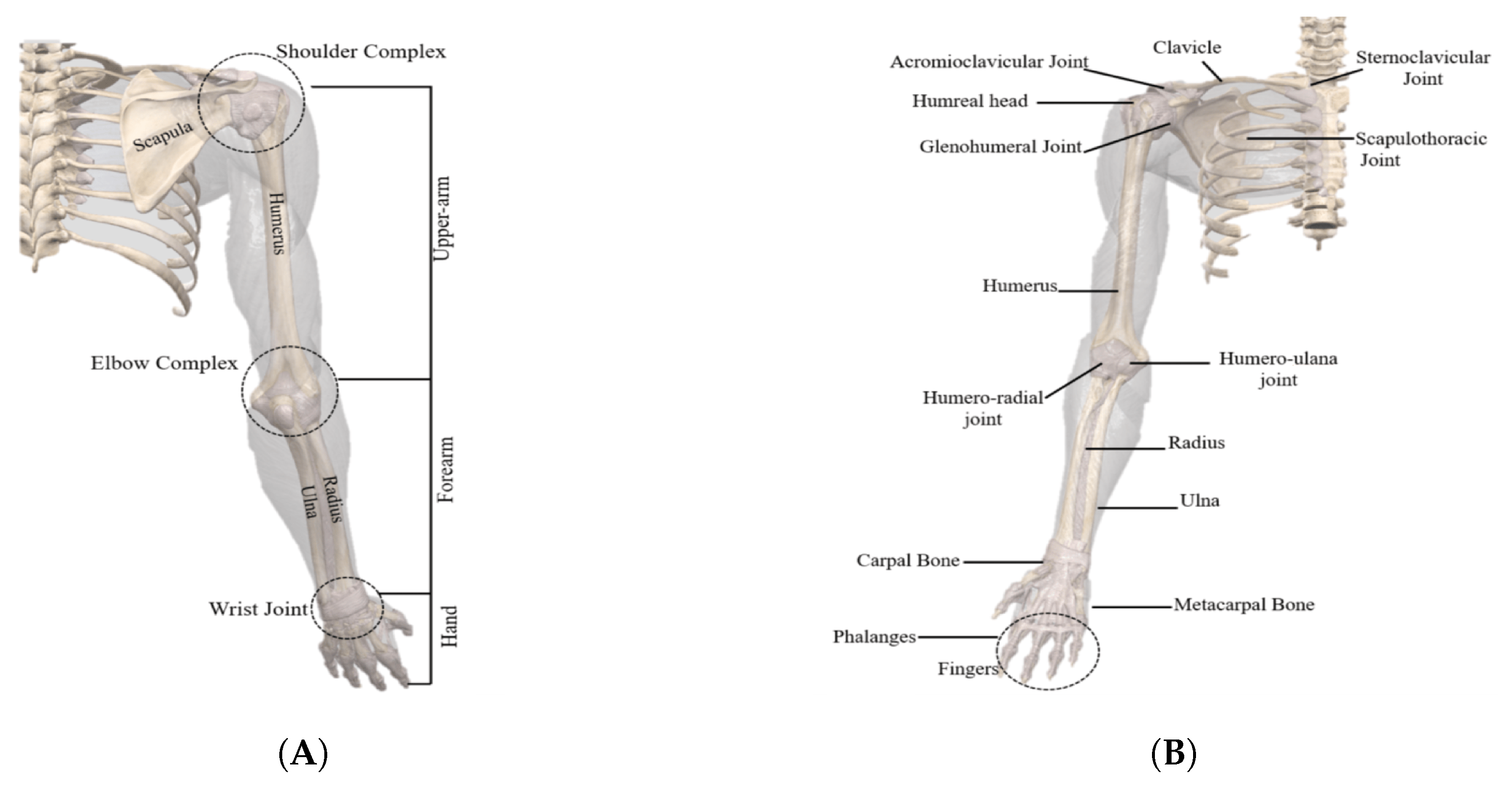
At a skeletal level, the upper limb is made up of various bony elements, organized as follows: The shoulder is made up of the clavicle, the scapula, and the humerus. It is with the latter that the connection to the elbow is made. This bone complex also joins the radius and ulna, the bones of the forearm [
6].
In the shoulder, there are four joints: the glenohumeral, acromioclavicular, sternoclavicular, and scapulothoracic joints. In the elbow, there is a synovial-type joint made up of two distinct joints, one between the humerus and ulna (humeroulnar joint) and the other between the humerus and radius (humeroradial joint). This can be seen in
Figure 4B.
The primary movements of the shoulder complex are abduction and adduction, internal and external rotation, and shoulder flexion and extension. Many of the exoskeletons developed only consider the glenohumeral joint to model the shoulder mechanism, producing a 3 DOF joint. The glenohumeral joint is commonly referred to as a ball-and-socket joint, formed between the humeral head joint and the glenoid cavity. However, the glenohumeral joint has an instantaneous center of rotation that changes with the movement of the human upper limbs [
7].
The elbow joint is 1 DOF, with the primary movements being flexion and extension [
6]. Similarly, the forearm also has 1 DOF, with its primary movement being pronation and supination.
To support the biomechanical overview of the upper limb,
Table 1 presents the main joint movements, their average Range Of Motion (ROM), and the primary muscles involved. ROM refers to the maximum angular movement that a joint can perform, measured in degrees, and is essential for understanding joint capabilities in exoskeleton design [
8,
9,
10].
4. Upper-Limb Exoskeletons
This section aims to review existing exoskeletons in order to understand existing designs as well as the ways in which inputs are read and the types of actuators used. The reviewed exoskeletons are covered in chronological order from the most recent to the oldest and are separated into two categories, assistive and rehabilitation. For each example analyzed, a table summarizes the DOF, the associated joint (shoulder, elbow, or forearm), and the corresponding designated movements. To simplify the analysis, only one side of the body is considered, which means that in exoskeletons designed for both upper limbs, only the DOFs for one limb are counted in the table. This approach ensures consistency and avoids over-representation of bilateral systems.
4.1. Assistive Exoskeleton
4.1.1. Cable-Driven Exoskeleton
In 2024, Lim and Sharifi [
11] proposed a cable-driven exoskeleton to assist or rehabilitate users who suffer from spinal cord injuries. These injuries cause difficulties at the motor and sensory level and usually escalate to long-term disability. The exoskeleton reached a total weight of 7
and had three DOF, using a BrushLess Direct Current (BLDC) motor and a cable system to transmit the motor’s power to the joints. The motors used were AK80-64s (CubeMars, Nanchang, China) [
12], which produce around 48
nominal torque and 120
peak torque. However, only 33
peak torque was obtained at the shoulder joint and 18
of torque at the elbow joint. The motors were placed in a carbon fiber box and connected to the joints via the cable system, which is then attached to the user’s back.
The project did not use sensors to detect the operator’s movement; a sine wave was introduced to generate movement. To control the motors, tests were carried out at a reduced speed, and a Proportional–Integral–Derivative (PID) tuning was performed, obtaining the proportional gain (), integral gain (), and derivative gain () that allowed for more efficient control of the motors—always considering the limits of human movement—and using Velcro straps to attach the exoskeleton to the user. After carrying out the tests, the authors were able to conclude that the components could withstand the torque applied by the cable system without causing excessive deformation. These experimental tests also validated the intended movement of the exoskeleton, abduction/adduction of the shoulder, flexion/extension of the shoulder, and flexion/extension of the elbow. The authors have thus validated the concept of the exoskeleton, which is lightweight, powered by a cable system, and respects human movements.
The corresponding degrees of freedom (DOFs) and primary movements for this system are summarized in
Table 2.
4.1.2. Pick-and-Place Upper-Limb Exoskeleton
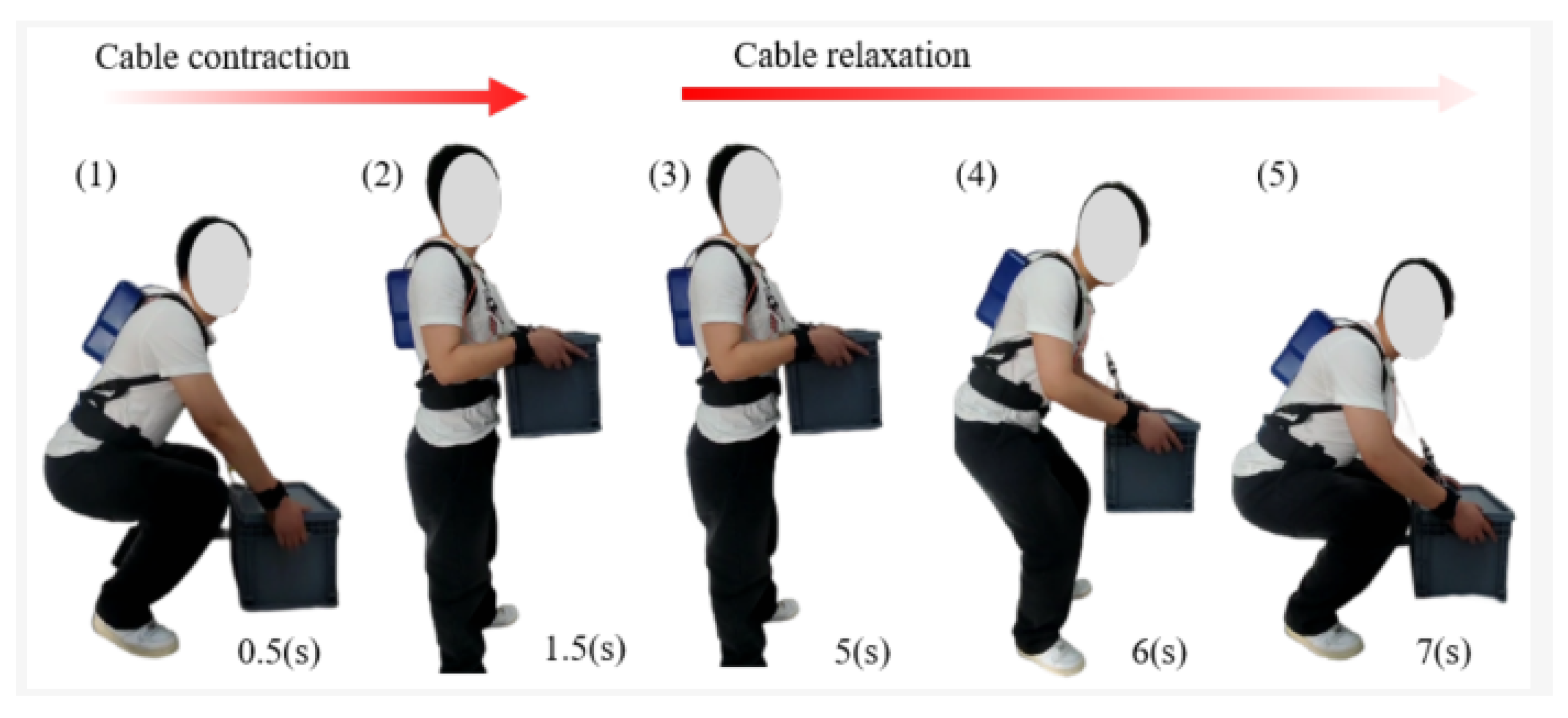
In the same year, Wang et al. [
13] developed and tested a pick-and-place upper-limb exoskeleton with the main function of pick-and-place, as seen in
Figure 5. To counteract upper-limb injuries and fatigue caused by heavy lifting operations, the authors used the TMOTOR AK80-6 BLDC motor (CubeMars, Nanchang, China) [
14], which produces 12
of peak torque and is powered by a 24 V lithium battery. The power was transmitted via a system of cables, resulting in a weight of just 4
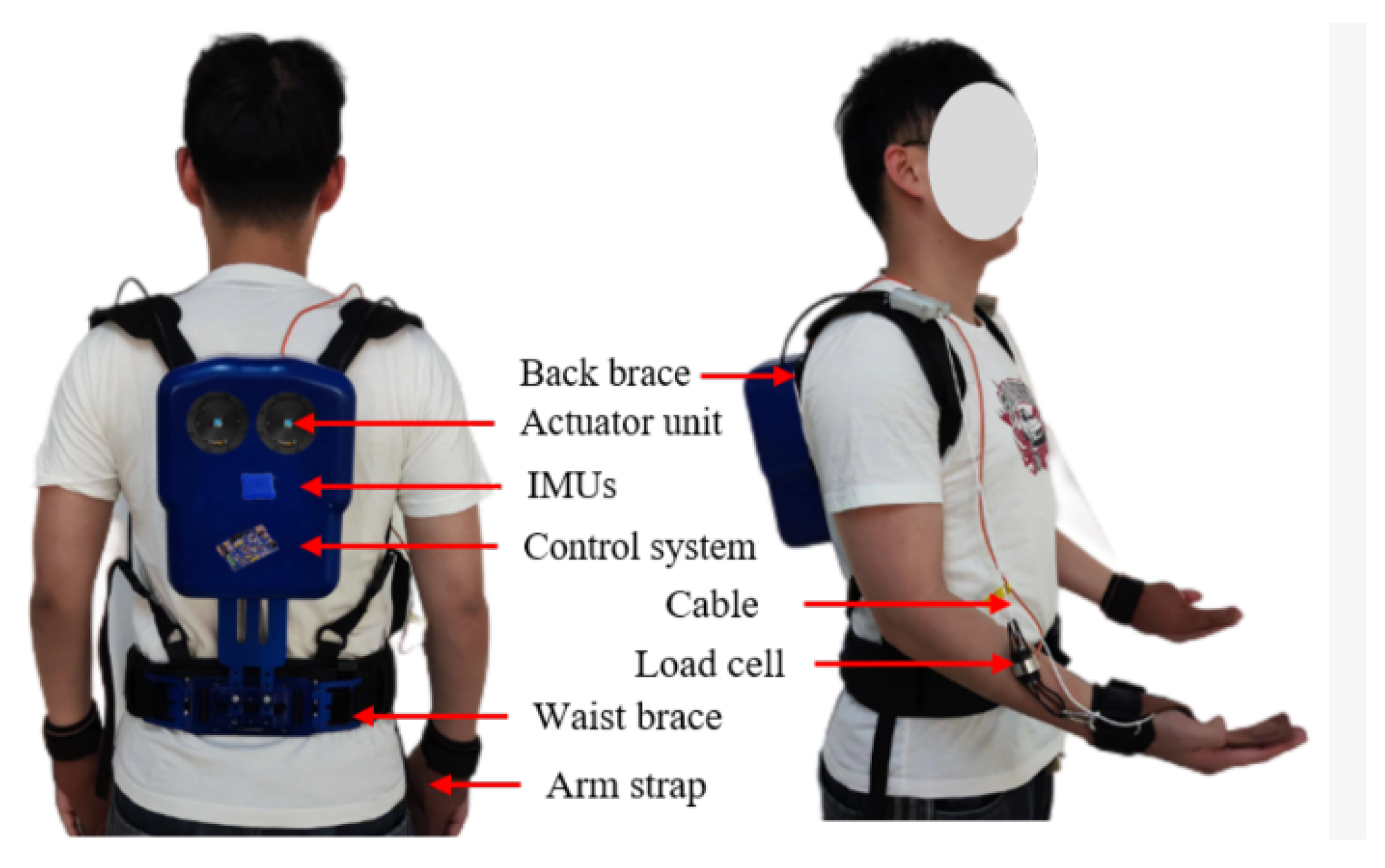
, so that the user does not have to exert a considerable amount of effort to wear the device. The exoskeleton was controlled using a fuzzy PID controller to obtain a smooth response of the cable tension that the exoskeleton needed to produce. The authors also used Inertial Measurement Unit (IMU) sensors to read the angular movement of the joints and use it as control feedback.
The human shoulder has a total of seven Degrees of Freedom, which means that rigid exoskeletons with fewer Degrees of Freedom can cause injuries, which is why the authors preferred to use flexible materials when developing their exoskeleton, resulting in the prototype shown in
Figure 6.
The authors carried out two experimental evaluations, first testing the range of movement of the exoskeleton, concluding that it has a low level of interference, with a reduction in shoulder range from to . They then carried out tests to understand the assistive effect of the exoskeleton, verifying that it is generating support for the user. The authors chose to read surface ElectroMyoGram (sEMG) signals when lifting loads of 5 , 10 , and 15 to make a comparison with and without the exoskeleton. The conclusions were that they significantly reduced muscle activity, and thus were able to demonstrate the support provided by the device and confirm its efficiency in providing physical support and reducing muscle strain during repetitive tasks.
The corresponding degrees of freedom (DOFs) and primary movements for this system are summarized in
Table 3.
4.1.3. Cable-Driven Upper-Limb Exosuit
In 2024, Guo et al. [
15] proposed an exosuit for the upper limb to increase human capacity, namely in rock climbing, rope climbing, and carrying boxes. To this end, they developed a soft exoskeleton made with non-stretchable nylon fabric and powered by a system of two cable-driven actuators. The authors also used a system of pressure-measuring gloves to detect when the hand closes and opens, using this to control the system. Excluding the weight of the batteries, the exosuit weighed approximately
. They calculated that the system, using two T-MOTOR AK80-6 BLDC motor [
14], could produce a maximum of 340
, which would be equivalent to lifting 34
. Although the authors do not state the exoskeleton’s Degrees of Freedom, it is similar to the 2 DOF exoskeleton previously discussed in
Section 4.1.2. Each motor comprises a PID controller with feedback being generated by the pressure-measuring gloves. To validate their solution, the authors used EMG signals during barbell lifts and the lifting of a 10
box by five healthy people. After several tests, a reduction in the amplitude of the EMG signals was observed, comparing the signals with and without the exoskeleton. In the future, they intend to improve the mechanical system of the exoskeleton and carry out tests in a climbing environment.
The corresponding degrees of freedom (DOFs) and primary movements for this system are summarized in
Table 4.
4.1.4. Assistive Exoskeleton with Soft Pneumatic Actuators
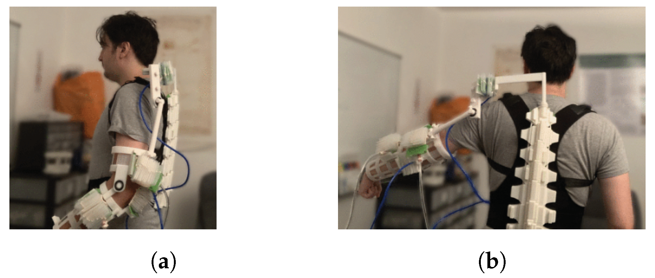
In 2023, George et al. [
16] had the objective of developing a lightweight exoskeleton with soft pneumatic actuators. Their motivation was muscle weakness caused by diseases such as stroke or trauma, which is typically treated using physiotherapy and assistive tools. However, many devices lack customization and affordability. For that, they built the exoskeleton using materials such as plastic using three Dimensional (3D)-printing, to be soft actuated, and to have a high number of DOF, which, in this case, was seven. With this system, the exoskeleton was able to obtain a peak torque of
and a weight of
, of which 572
was solely from plastic.
The exoskeleton acts actively on the elbow, shoulder, forearm rotation, and shoulder rotation. It acts passively with an anti-gravity system using elastics so that the user does not feel the weight of the exoskeleton as much. The presented exoskeleton is shown in
Figure 7.
An electronic goniometer was used to measure the angular position of each joint. Proportional control was used to compare the sensor readings with the target values. As the exoskeleton is pneumatic, if there was a discrepancy between the target angle and the sensor reading, the actuation power would be altered to correct the discrepancy.
The authors carried out tests on the exoskeleton to assess the performance of the actuators in different scenarios. Initially, the measurement of the actuator angle showed that, when isolated, the actuators showed unpredictable variation. However, when integrated into the exoskeleton joints, the addition of inertia provided smoother and more controlled movements. Torque measurements indicated that the actuators generated consistent torques as the joint angle increased, with values ranging from to as the angle increased. In addition, tests with participants confirmed the effectiveness of the exoskeleton in assisting movement, allowing users to hit targets in a three-dimensional space with controlled times, demonstrating the system’s ability to optimize joint movement and improve the efficiency of assistive support during dynamic tasks.
The authors have succeeded in obtaining a light and simple exoskeleton and, in the future, intend to use EMG signals to actuate the exoskeleton.
The corresponding degrees of freedom (DOFs) and primary movements for this system are summarized in
Table 5.
4.1.5. A 6 DOF Dual-Arm Exoskeleton
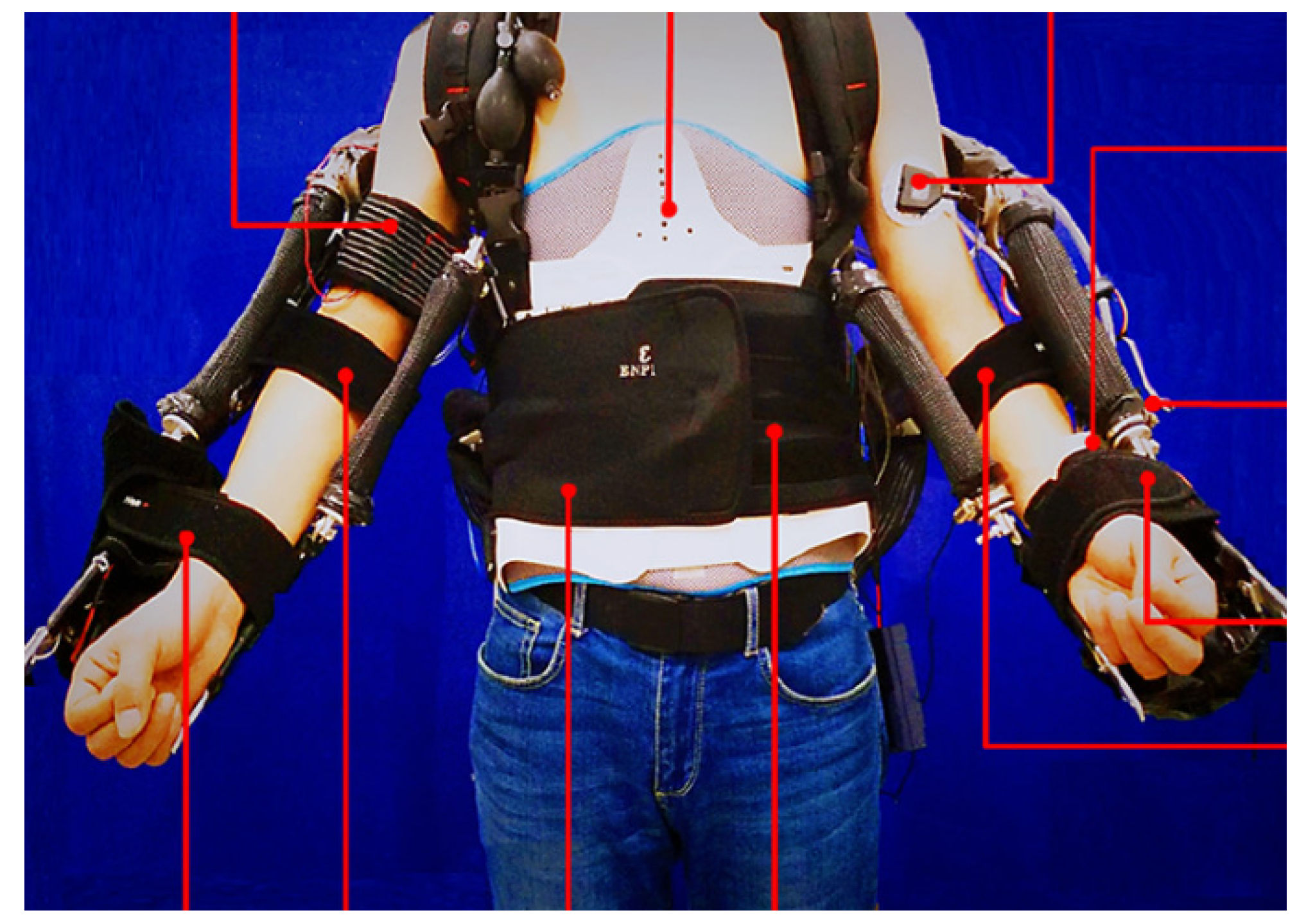
In 2020, Hao et al. [
17] designed a safe human–robot interactive control for the 6 DOF exoskeleton shown in
Figure 8, with the objective of reducing the risk of muscle pain, fatigue, and musculoskeletal disorders in workers during manual lifting tasks, which involve repetitive movements of lifting, holding, and stacking heavy objects. The exoskeleton has a three-level hierarchical control system, where the high level reads the sEMG signals to detect the user’s movement, the middle level uses a Hammerstein adaptive virtual mechanical impedance controller to reduce overshoot and maintain a comfortable torque level for the user, and finally, the low level comprises the motor controllers.
In addition to the sEMG sensors, a pneumatic soft sensor was used to measure the force exerted by the exoskeleton, and a heartbeat reader was used to measure the user’s effort. When fully assembled, the exoskeleton had a mass of and produced at least 30 .
The corresponding degrees of freedom (DOFs) and primary movements for this system are summarized in
Table 6.
4.1.6. Assistive Upper-Limb Exoskeleton for Manual Handling Tasks
In that same year, Yan et al. [
18] developed a 2 DOF exoskeleton to help industrial workers, who engaged in repetitive handling tasks, and patients with injuries in their upper limb due to accidents, spinal cord injuries, and strokes. The exoskeleton was moved by cables and actuated by electric motors. The authors were able to achieve an exoskeleton that weighed approximately 2
and used an adaptive Proportional-Derivative (PD) controller to control the exoskeleton.
The authors were able to verify the effectiveness of the assistance on the patients’ muscles by reading the variation in the intensity of the EMG signals when performing the tasks with and without the exoskeleton, obtaining an average of approximately 40% per muscle group. The results showed that the EMG signal amplitude, when lifting a load with the exoskeleton, was the same when lifting without the exoskeleton in the (biceps femoris muscle) BFW, so it was calculated that the exoskeleton was lifting 3 , then at the elbow joint, it was producing around 9 of torque.
The corresponding degrees of freedom (DOFs) and primary movements for this system are summarized in
Table 7.
4.1.7. Exoskeleton Using a Double Parallelogram Linkage
In their work published in 2018, Christensen and Bai [
19] developed a shoulder joint that could perform internal and external rotation of the shoulder to be used in an exoskeleton. To achieve this goal, a passive joint was created using a Double-Parallelogram Linkage (DPL) system.
To this end, an exoskeleton was developed with 4 DOF, three of which are active and one of which, the DPL, is passive. BrushLess Direct Current (BLDC) motors were used for actuation, along with a harmonic gearbox and a force-sensing resistor as a main input. A study was carried out in which the authors simulated the daily activities of human beings with loads of up to 5
. Subsequently, they decided to scale it down to 50% of the max load tested. With this exoskeleton, they were able to perform the movements of flexion/extension, abduction/adduction, and medial rotation of the shoulder, as well as flexion/extension of the elbow. This exoskeleton is mobile, and the shoulder joint, as well as the rest of the exoskeleton, is made of 7075 aluminum alloy [
20], with the weight of the shoulder joint being 2650
.
With this installation of the shoulder joint in the upper body exoskeleton, the authors concluded that the joint has a great range and is a good choice for portable exoskeletons.
The corresponding degrees of freedom (DOFs) and primary movements for this system are summarized in
Table 8.
4.1.8. Upper-Limb Exoskeleton Robot for Refractory Construction
In 2018, Yu et al. [
21] developed an upper-limb double arm exoskeleton with an air balancer and seven DOF. The exoskeleton was developed to help with refractory construction operations in furnaces, being designed to have great three-dimensional space mobility with the load and also be able to help the operator move loads of up to 50
.
In the development of the exoskeleton, 6-axis Force/Torque (F/T) sensors were used to obtain the link between the operator and the exoskeleton. After the final design of the exoskeleton was completed, it weighed , and since it did not have support for the lower limbs, the exoskeleton had to be mounted on an air balancer. To perform the task of lifting 50 on the end effector, the actuators were required to produce of peak torque. To obtain this value, Direct Current (DC) motors were used with a harmonic box connected by a pulley reduction gear. The pulley-reduction gear allowed for better positioning of the motor and pulley due to its flexibility. Using F/T sensors to control the position of the exoskeleton, the authors found that they required a high gain, which caused responses that were very sensitive to sensor errors. For this reason, a speed-tracking torque control was developed, updating the Proportional-Integral (PI) references every 2 . To promote safety, limits were added to the joints, and the damped least-squares method was used to avoid singularities.
The authors carried out tests in simulated refractory construction operations, including lifting, transportation, and alignment. In the tests, the exoskeleton allowed the operator to transfer refractories weighing up to 50 kg without difficulty, and during these tests, the maximum displacements of the exoskeleton as well as its speed of movement could be obtained. In addition, the combination of movements in the two arms made it possible to perform complex three-dimensional movements for aligning and manipulating objects. They also concluded that the dynamic control between the sensors and actuators was effective, ensuring adequate response without causing discomfort to the user, although the air balancer occasionally caused slight imbalances due to the repeated weight of the refractory.
With all these points, the authors concluded that the exoskeleton operator could easily move a load of up to 50 and perform repetitive tasks found in the refractory market.
The corresponding degrees of freedom (DOFs) and primary movements for this system are summarized in
Table 9.
4.1.9. Cable-Driven Exoskeleton with Gravity Compensation
In 2017, Sui et al. [
22] developed a wearable exoskeleton to help workers in jobs that require them to move loads continuously for long periods, which can lead to shoulder and elbow injuries and serious on-the-job injuries. This reduction in workload improves worker health and reduces costs for these companies. To this end, an exoskeleton with 5 DOF and a weight of
was developed.
To develop the exoskeleton, the authors used 2 DOF for the shoulder, 1 DOF for the elbow, 1 DOF for forearm rotation using a double parallelogram system, and finally a passive DOF for elevation and depression at the sternoclavicular joint with a gravity balance system. A cable-driven system and a belt reduction system were used to actuate the exoskeleton. A gravity balance method was also used to reduce the effort required from the exoskeleton actuator during movement. With the aim of reducing the weight of the exoskeleton, a spring system was chosen for the gravity balance system. To control the exoskeleton, the angular position of the joint was considered, accounting for the torque compensation due to losses, such as friction torque. This allowed the authors to conduct joint-tracking tests, which consisted of a sinusoidal reference of angle and angular velocity provided for the exoskeleton’s elbow flexion and extension movement. It was checked whether the exoskeleton followed accurately to validate the efficiency and safety of their system. To confirm that the exoskeleton was helping while performing tasks, disposable electrodes were placed on the arm so the EMG could be read and a comparison of effort could be conducted between the absence and use of the exoskeleton when lifting .
With this exoskeleton, the authors concluded that the application of the gravity balance made it possible to reduce the stress on the motors and subsequently use smaller motors and gearboxes, which helped obtain a lighter exoskeleton.
The corresponding degrees of freedom (DOFs) and primary movements for this system are summarized in
Table 10.
4.2. Rehabilitation Exoskeleton
4.2.1. Upper-Body Exoskeleton for Stroke Patients
In 2025, Talley et al. [
23] developed a 3 DOF exoskeleton for the rehabilitation of patients suffering from arm function problems, such as people who have suffered a stroke. Plastic was used for the exoskeleton body, AK80-8 motors for actuation, as well as a servo motor and cable system for the elbow actuation. To control the exoskeleton, the authors used a mirror system, where IMUs were added to the patient’s good arm and the exoskeleton attached to the arm that is blocked, then when the good arm is moved, the exoskeleton copies the movements, helping to rehabilitate the patient. After several tests, the authors concluded that the exoskeleton was able to copy the movement with a few deviations.
The corresponding degrees of freedom (DOFs) and primary movements for this system are summarized in
Table 11.
4.2.2. Reconfigurable 7 DOF Upper-Limb Rehabilitation Exoskeleton
In 2024, Wu et al. [
24], developed an exoskeleton with 7 DOF to help patients who have suffered from strokes. To increase versatility, the exoskeleton developed can be modified to switch between the right and left arm; it also has a built-in gravity compensation system, helping to take strain off the electric motors. To control the exoskeleton, the authors used a system with six-dimensional force-torque sensors, allowing them to sense the patient’s movement intentions. The exoskeleton can be used on different arms and can be adjusted to the physical structure of the patients, from height to arm length. The system used electric motors which, depending on the joint and movement, produced from 3
to 25
of nominal torque. To control the whole system, the authors used sliding mode control and dynamic movement primitives to achieve smooth control of the exoskeleton, and plan to add EMG readings in the future.
The corresponding degrees of freedom (DOFs) and primary movements for this system are summarized in
Table 12.
4.2.3. POWERUP Exoskeleton
In 2024 Urendes et al. [
25] developed a passive exoskeleton made of plastic. Using plastic gives the exoskeleton a mass of only
and simultaneously reduces monetary costs, making it ideal to be used in health clinics for the rehabilitation of children with neuromotor dysfunctions. To this end, the authors developed a 5 DOF exoskeleton called POWERUP, shown in
Figure 9, made entirely of Poly-Lactic Acid (PLA) filament and using elastics to perform the actuation.
Several exoskeleton modules were designed as it was to be used by children between the ages of 6 and 18 years old with different arm sizes. As a parameter, the authors decided that the exoskeleton should passively lift at least . As the idea was to use it for therapy, it was fixed to a mobile support. Two modes of operation were also developed, one that removes weight from the patient’s arm, and one that generates resistance to movement to help the patient regain movement and strength.
Finally, to validate the exoskeleton, they used EMG signal readings and were able to confirm that the exoskeleton was indeed helping, thus validating the design.
The corresponding degrees of freedom (DOFs) and primary movements for this system are summarized in
Table 13.
4.2.4. A 5 DOF Elbow-Wrist Exoskeleton
In 2019 Wu et al. [
26] developed a 5 DOF elbow-wrist exoskeleton to facilitate the provision of repeated and progressive rehabilitation exercises that are essential for the effective recovery of patients with upper-limb disabilities. In this development, the authors opted to use smaller, simpler motors to avoid the weight, inertia, and volume issues of more powerful motors, so they was able to obtain a 3
exoskeleton.
By integrating the positioning of the actuators, sensors, and transmission mechanism, the authors were able to develop a compact exoskeleton with minimal friction, thereby achieving effective performance for forearm rehabilitation through the use of an impedance controller to dynamically regulate the exoskeleton.
For actuation, the exoskeleton uses five Series Elastic Actuators (SEA) motors. These motors can provide accurate force/torque control obtained from the deformation of the linear SEA spring. In total, the five linear SEA weighed only .
The corresponding degrees of freedom (DOFs) and primary movements for this system are summarized in
Table 14.
4.2.5. Exoskeleton Actuated by the Soft Modules
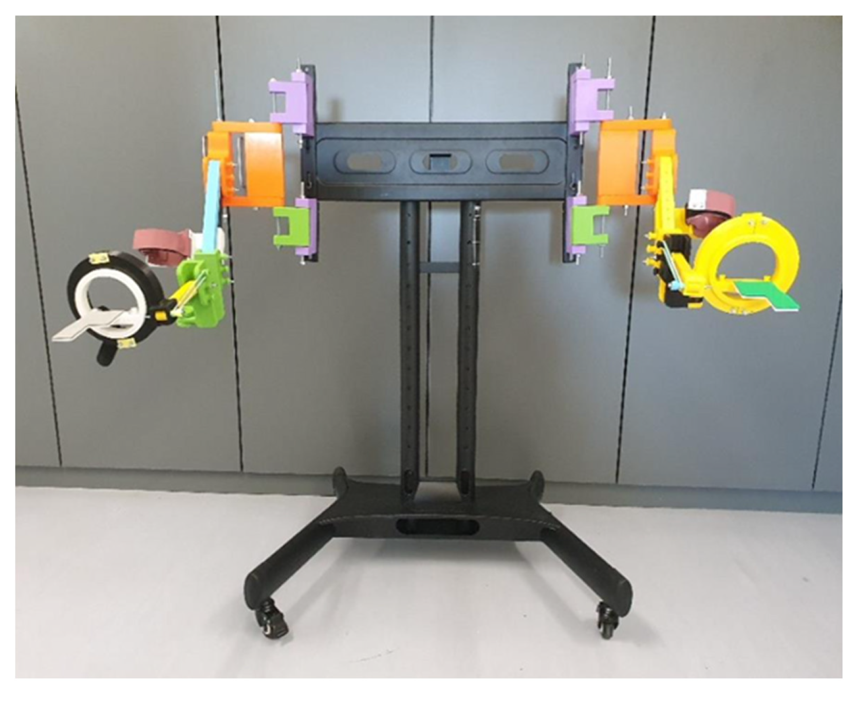
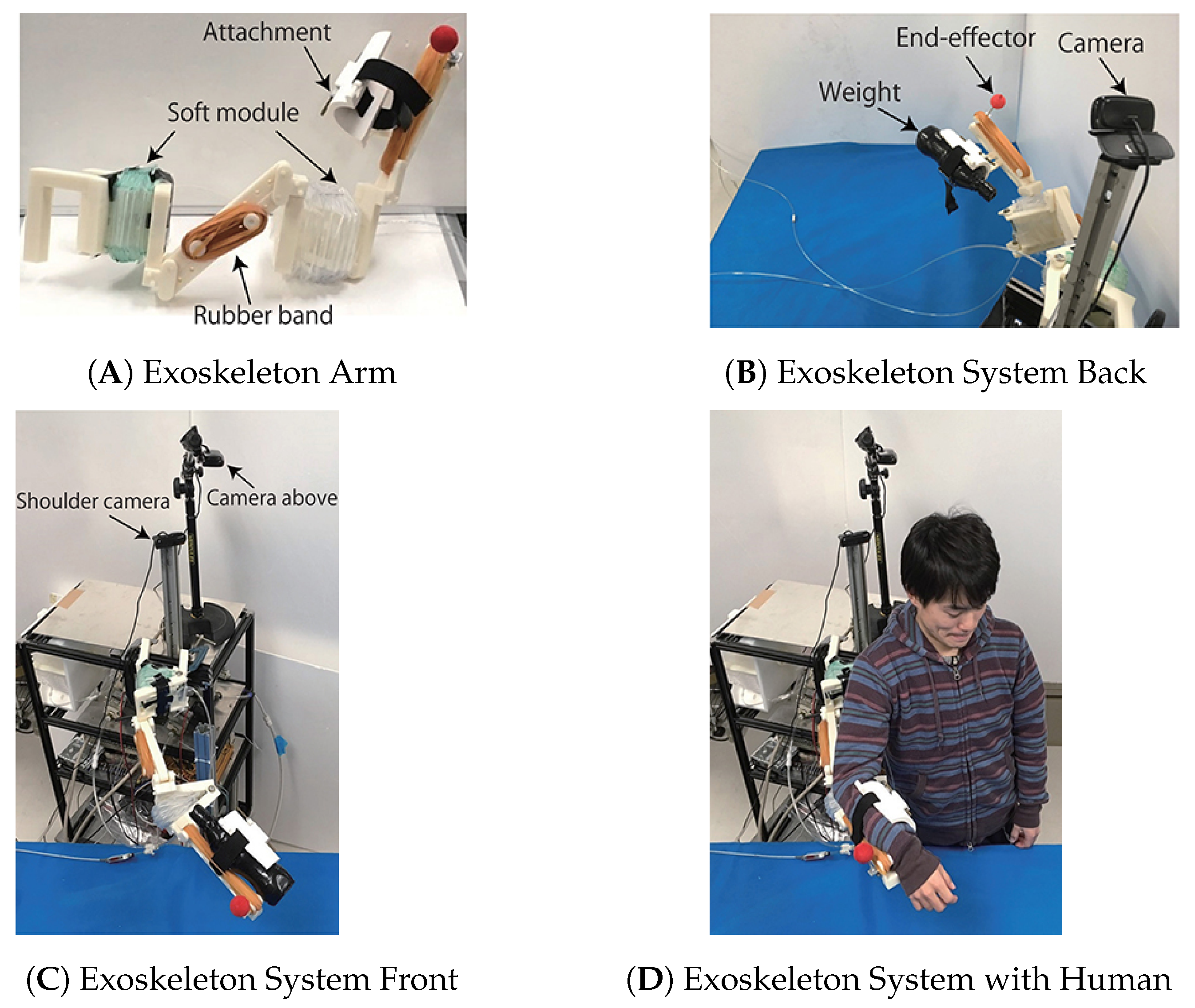
In 2017, Oguntosin et al. [
27] used soft actuators in an exoskeleton to make it ultra-light and to use computer vision to detect the movement and then control the actuators. This was achieved using plastic for the connections, and a pneumatic system was used for the actuation. The exoskeleton was attached to an object such as a chair, as shown in
Figure 10. The author’s intention in creating the exoskeleton with these properties is to ensure that it can be used in a medical environment to rehabilitate patients, keep the manufacturing cost low, avoid the use of rigid robotic systems controlling the upper limb, and reduce intervention by a medical professional.
With this project in mind, an exoskeleton was developed with four DOF, two passive and two active, and a video-based control architecture. With the printed parts made of Acrylonitrile Butadiene Styrene (ABS) plastic and the soft actuators made of Polyethylene, a weight of 957 was achieved. As the actuators are pneumatic, it was decided that the acceptable pressure values would be to 30 . With these values and the exoskeleton assembled, it could be verified that at the maximum positive pressure (30 ), the elbow joint of the exoskeleton produced 9 , and at the maximum negative pressure ( ), it produced . Considering that the length of the forearm is 30 , the maximum load would be 3 when it produces 9 of torque and when it produces . As the exoskeleton is designed to help the person rehabilitate the arm in a post-stroke situation, these values are sufficient.
With this exoskeleton, the authors were able to achieve the proposed objectives: To have few DOF, to have precise control of movement, which was achieved through camera control, to be wearable and usable in everyday life, and finally, the assistance had to be compatible with muscle contraction to provide conformity in joint dynamics.
The corresponding degrees of freedom (DOFs) and primary movements for this system are summarized in
Table 15.
4.2.6. Parallel-Actuated Exoskeleton
In the same year, Hsieh et al. [
28] designed a parallel-actuated 6 DOF exoskeleton for post-stroke rehabilitation, as these patients require repeated and progressive training exercises, and the use of an exoskeleton will reduce the cost of therapist labor. The design uses linear Series Elastic Actuators (SEA) actuators with an impedance control to move the exoskeleton and force sensors to obtain the reference of the arm.
Since this exoskeleton was for the upper limb, it was necessary to study the displacement of the humeral head. The conclusion was that during abduction and adduction of the shoulder, the center point moved about 9 in the vertical z-axis and about 8 horizontally in the y-axis. With this study, the authors concluded that the displacement of the shoulder during movement is too high to be negligible and must always be taken into account when developing an exoskeleton that acts on the shoulder. To solve this, an adaptive mechanism was used, which meant that there was no need for precise alignment between the shoulder and the exoskeleton. So, therefore, the exoskeleton had two active DOF for movement, and four passive DOF for the adaptive mechanism.
The prototype, weighing around , was developed, but since the exoskeleton is for rehabilitation, it was fixed so that the patient does not need to support the exoskeleton. However, the exoskeleton was designed exclusively for the shoulder, and it was later necessary to develop the actuation of the shoulder internal/external rotation and elbow flexion/extension to achieve full control of the upper limb.
With the exoskeleton prototype built, the authors deployed it in a dummy arm made of aluminum so they could carry out some tests, starting with an impedance control test, where they had the exoskeleton follow a sinusoidal reference to move the dummy’s arm, concluding that there was a slight misalignment caused by the motor due to a lack of power. They then carried out a kinematic misalignment experiment in which they calculated the misalignment of the passive joints and then measured them, obtaining the same results, thus validating their kinematics. Finally, they performed a test in which the passive joints were locked and compared them with unlocked joints. They observed a significant increase in force, resulting in dangerous and uncomfortable movements.
The corresponding degrees of freedom (DOFs) and primary movements for this system are summarized in
Table 16.
4.2.7. Neurorehabilitation Exoskeleton
In 2017, Nam et al. [
29] studied patients suffering from post-stroke with spastic elbow and/or wrist joints with the use of a 2 DOF exoskeleton to understand the reaction of the exoskeleton when it encounters spasticity during movement. The authors wanted the exoskeleton to be able to help rehabilitate patients with a high degree of spasticity. For this purpose, a 2 DOF exoskeleton, was used. This exoskeleton comprises 1 DOF in the elbow extension and flexion, and 1 DOF on the wrist dorsiflexion and palmar flexion. Furthermore, they used a mirror system in order for the patient or medical professional to force the arm that has reduced mobility to move. For actuation, two BLDC motors were used, with enough torque to compensate for the patient’s blocked movement, and torque sensors mounted on each of the joints to obtain torque data between the exoskeleton and the human arm during therapy. Having observed a torque of 22
during the experiment implies that the motor has a value higher than this.
With this study, the authors were able to obtain valuable data on the torque that the patient, with the arm blocked or limited due to a stroke, was able to produce, thus allowing future projects to be scaled according to these values.
The corresponding degrees of freedom (DOFs) and primary movements for this system are summarized in
Table 17.
4.2.8. Cable-Driven Arm Exoskeleton
In 2016, Cui et al. [
30] had the objective of improving the already developed CAREX [
31] exoskeleton to help people who suffer from movement disorders and reduced muscle strength by building it with 7 DOF and having it be actuated by cables, using it for complete arm rehabilitation, resulting in the CAREX-7.
The exoskeleton was fixed to a chair, and to achieve the 7 DOF, it uses eight cables for actuation. Of the 7 DOF, 3 are for shoulder movement, 1 for elbow movement, and finally 3 for wrist movement. The exoskeleton is attached to the user via four cuffs. To detect the user’s position, an IMU was used; furthermore, to receive feedback on the tension the cables were producing, load cells were used at the end of the cables.
To control the exoskeleton, the authors used a control scheme based on the “assistance as needed” paradigm, which has already been used by many researchers. This scheme evaluates the robot’s required assistance to the user by measuring the trajectory tracking error of the end effector. The force field controller is a typical assistance-as-needed control scheme, which is applied in reach-movement training tasks.
The authors concluded that the CAREX-7 exoskeleton assists the seven joints while maintaining weight, and because the actuation is performed by cables, there is no need for great precision in the alignment of the joints. For future development, the authors want to collect EMG signal readings and increase the comfort of the exoskeleton.
The corresponding degrees of freedom (DOFs) and primary movements for this system are summarized in
Table 18.
4.2.9. Rehabilitation Exoskeleton for the Elbow Joint
In 2016, Copaci et al. [
32] proposed an elbow exoskeleton with 2 DOF. The device was actuated by a system based on Shape Memory Alloy (SMA), allowing the weight and noise of the exoskeleton to be reduced. It was developed for a person weighing 70
and with a height of
.
The authors had already carried out other tests with the SMA-based actuator, so they could conclude with a few more tests that the exoskeleton would only need four actuators and produce a torque of at least . With these values, a design can be defined for the exoskeleton, which will be made of plastic, and in a simple way for easy assembly. For patient safety, the exoskeleton also includes mechanical movement limitations to ensure it does not exceed the human limit. With this configuration, the exoskeleton weighs less than 1 .
The authors concluded from the tests that the exoskeleton was very light and low-cost, and great for slow rehabilitation as it performs elbow flexion from to in 10 and from to in 15 .
The corresponding degrees of freedom (DOFs) and primary movements for this system are summarized in
Table 19.
5. Discussion
After analyzing the various articles in the previous section,
Table 20,
Table 21,
Table 22 and
Table 23 were constructed, providing an overview of the different exoskeletons, from the type of actuators to the construction material.
The torque values presented on
Table 21 all refer to the max torque in the elbow flexion/extension movement, as this movement was acted on by all the exoskeletons presented, except the exoskeleton in
Section 4.2.6.
Firstly, assistive exoskeletons tend to be portable, and rehabilitation exoskeletons tend to be fixed. Second, the most commonly used sensor is the force or torque sensor. Furthermore, assistive exoskeletons tend to be heavier. In the presented exoskeletons, torque appears to be more closely related to the type of actuation and overall design than to the intended objectives. The same applies to the number of degrees of freedom, which ranges from 2 DOF to 7 DOF.
The most commonly used actuation mode was the cable system, as it effectively addresses two main issues associated with placing electric motors directly at the joints: the first is the space constraint since motors can be bulky and limit joint mobility; the second is the additional load they impose—particularly critical when actuating shoulder flexion/extension and elbow flexion/extension—where mounting the motor at the elbow would result in extra weight that the shoulder joint must also support. An example of this design consideration can be found in the exoskeleton presented in [
11]. Using electric motors with a gearbox directly in the joint is more efficient, as the adjustment of the cable system is not needed to operate it, and its control system is more direct. However, as previously stated, one of its problems is that the weight of the motor starts to influence the movement. The other issue regarding an electric motor with a gearbox is that to produce a lot of torque, it can be too heavy to wear on the operator’s back, so it has to be fixed, like the refractory construction exoskeleton.
A common feature observed in several of the exoskeletons presented in the Soft-actuated, Construction, Wearable upper-limb, Parallel-actuated exoskeleton, and Reconfigurable exo is an anti-gravity system that aims to “move” the weight of the exoskeleton from the arm to the operator’s back, if it is portable, or to the support if it is fixed.
This system has several forms. For example, one could be like that of the exoskeleton from the article by Sui et al. [
22], where in these systems, springs are used to support the weight of the exoskeleton. In other words, the spring assists the actuation system so that the motors do not have to exert so much force. The biggest defect of this system is if for some reason the exoskeleton is upside down, the spring will hinder rather than assist. Another system that could be used is a counterweight system, where a counterweight would be added to the joint, performing the same task as the spring. The main defect of this system is that it increases the overall weight of the exoskeleton. For this reason, the system has to be evaluated on a case-by-case basis.
In
Figure 11 it can be seen that the movements most covered by the exoskeletons shown are flexion/extension of the elbow and flexion/extension of the shoulder. There are two main reasons for this: the first is that these movements are the easiest to detect and perform, especially the elbow movement. Secondly, apart from their ease, the movements are practically identical, so the control will also be identical. Another relevant point is that both the Pick-and-Place [
13] and the Exosuit [
15] exoskeletons, although designed with only 1 DOF, allow the operator to perform two distinct movements, thanks to their flexible construction.
To test the level of assistance provided by the exoskeleton for rehabilitation and assistance, the surface sEMG signal was measured, comparing the amplitude of the signal with and without the exoskeleton, where the amplitude of the signal is roughly equivalent to the operator’s effort [
22]. Depending on the sensor system that relates the movement of the arm to the movement of the exoskeleton, the effectiveness of the exoskeleton can also be seen by measuring how much force is exerted on the operator’s arm with the actuators switched off and comparing this to when they are switched on.
Table 21 shows the main material of each exoskeleton, when available. It is clear that the aluminum exoskeletons are heavier than the 3D-printed ones, as expected, except the cable-driven exoskeleton because it uses four motors which weigh nearly
. There is also a relationship between the torque the exoskeleton produces and the material, with aluminum ones tending to produce more torque. This is due to the great difference between the strength of aluminum compared to plastic, allowing for a greater output of power without the structure being damaged or even breaking.
Another growing issue, which is also the reason why several authors are opting for soft structures, is operator comfort. In a rigid structure, the center of action of the motors must be perfectly aligned with the operator’s joint, which is often not possible with the necessary precision, and as mentioned in
Section 3.1, the advantage of soft structures is that they adapt to the operator’s joint. This adaption drastically increases operator comfort. As the idea of exoskeletons in the future is to use them for several hours, a high level of comfort is a point to be considered when building an exoskeleton.
6. Conclusions
For the purpose of developing an upper-limb exoskeleton for industrial environments such as agriculture, the previous study highlights two key aspects in its development: (i) exoskeleton design and (ii) testing and validation.
For design (i), portability is essential, since agricultural tasks are demanding and often in different locations. In addition, the exoskeleton must lift significant loads so that there is a high reduction in worker effort (for example, 10 kg requires motors that produce 70 torque), and the exoskeleton must be light and have the load well-distributed over the operator’s back. For the motors, gearboxes can be directly connected to the joints of the exoskeleton so that there is as little loss of torque as possible, which is not the case with the cable system. It can also be seen that a more resistant material, such as aluminum, is necessary due to the high stress that the structure will have to undergo, and it is preferable to 3D-printing due to its low resistance. An anti-gravity system, which has been described in several of the documents reviewed above, could be implemented in order to prevent the weight from overloading the operator’s arm. As presented in the various documents, the control system could be via sensors for precise interaction between the operator and the exoskeleton, as well as the use of safety measures such as movement limitations and speed/current limits to maintain realistic ranges of movement.
For testing and validation (ii), as with several studies, it can be performed using the sEMG signals and effort comparisons with and without the exoskeleton to obtain a methodical analysis of the benefit of the exoskeleton in the performance of tasks by the operator.
With these points in mind, it is possible to obtain a clear path for the initial development of the exoskeleton, as well as a visual and widely used metric to measure the effectiveness of the exoskeleton in reducing effort during various tasks.


