Article

EMG-Driven Shared Control Architecture for Human–Robot Co-Manipulation Tasks †

by
Francesca Patriarca
,
Paolo Di Lillo
* and
Filippo Arrichiello
Department of Electrical and Information Engineering, University of Cassino and Southern Lazio, 03043 Cassino, Italy
*
Author to whom correspondence should be addressed.
This paper is an extended version of our published paper: Patriarca, F.; Di Lillo, P.; Arrichiello, F. EMG-Based Shared Control Framework for Human-Robot Co-Manipulation Tasks. In Proceedings of the 21ST International Conference On Informatics in Control, Automation and Robotics, Porto, Portugal, 18–19 November 2024.
Machines 2025, 13(8), 669; https://doi.org/10.3390/machines13080669 (registering DOI)
Submission received: 8 July 2025 / Revised: 25 July 2025 / Accepted: 27 July 2025 / Published: 31 July 2025
(This article belongs to the Special Issue Design and Control of Assistive Robots)

Abstract

The paper presents a shared control strategy that allows a human operator to physically guide the end-effector of a robotic manipulator to perform different tasks, possibly in interaction with the environment. To switch among different operational modes referring to a finite state machine algorithm, ElectroMyoGraphic (EMG) signals from the user’s arm are used to detect muscular contractions and to interact with a variable admittance control strategy. Specifically, a Support Vector Machine (SVM) classifier processes the raw EMG data to identify three classes of contractions that trigger the activation of different sets of admittance control parameters corresponding to the envisaged operational modes. The proposed architecture has been experimentally validated using a Kinova Jaco2 manipulator, equipped with force/torque sensor at the end-effector, and with a limited group of users wearing Delsys Trigno Avanti EMG sensors on the dominant upper limb, demonstrating promising results.

1. Introduction

Collaborative robotics refers to robotic systems that directly interact with humans in a shared workspace to jointly complete tasks. These human–robot teams aim to combine the versatility and decision-making capability of human workers with the precision, strength and repeatability of robots to improve both the quality and execution time of collaborative tasks. In this scenario, intuitive user interfaces that facilitate smooth human–robot cooperation, advanced sensors and control systems are used to enable the robot to safely operate close to humans [1]. Unlike traditional industrial robots, which operate in isolated environments and have physical barriers to be separated from human operators, collaborative robots (or cobots) can dynamically adapt to people and objects that enter their workspace [2]. This flexibility allows them to be employed in various contexts, such as manufacturing and assembly operations [3], logistics or in applications such as surgery to assist physicians in medical procedures [4].
Developing effective human–robot teams presents challenges such as providing the robot with situational awareness, establishing clear communication protocols, and ensuring safety without limiting the robot’s speed or range of motion to make physical interaction more intuitive [5,6]. To address these challenges, shared control techniques, in which both the robot and the human operator are involved as active parts in the control loop [7], have emerged as promising solutions to enable smoother interaction and to improve safety and task efficiency. By combining autonomous robot control with human decision making, shared control enhances the overall operational capabilities of the system [8]. In shared control, a human and an automated system, such as a robot, collaborate to regulate the system’s behavior, offering an effective solution for various applications, particularly in human–robot interaction scenarios [9]. It is evident that the ability to facilitate physical human–robot interaction (pHRI) during collaborative tasks is a pivotal element of shared control. To manage the dynamics of these interactions, an impedance/admittance control strategy is used for controlling robots to behave as virtual dynamic systems with adjustable impedance parameters [10,11], rather than just following their intrinsic dynamics. This allows the robot’s compliance and motion synchronization capabilities to be adapted to enhance both collaboration with humans and interaction with the environment [12]; thus the robot can adjust its dynamic behavior when physically interacting with an external agent, and the desired dynamic behavior can be replicated on a non-backdrivable manipulator to improve its physical interaction capabilities [13]. To enhance the performance of human–robot collaboration, the concept of human-like variable admittance parameter regulation has been proposed, which is based on the change rate of interaction force and the study of a human arm’s static and dynamic admittance parameters in human–human collaborative motion [14]. In physical human–robot interaction, the trajectory prediction of human motion also plays a pivotal role, as it allows robots to anticipate human movements and adapt their actions accordingly. This allows robots to minimize human interference, optimize task completion times, and improve overall performance during interaction [15]. Additionally, a method for variable admittance control that combines a human-like decision-making process and an adaptation algorithm, such as fuzzy inference system, to improve human–robot cooperation tasks is developed in [16].
Surface ElectroMyoGraphy (sEMG) sensors, which capture the electrical activity of muscles, play an important role in variable admittance control schemes to estimate the user’s movement intention, as described in [17,18] where the measurements of the operator’s muscle activation are used to adapt the virtual damping online. This has led to approaches based on the integration of EMG signals and adaptive admittance control architectures for several applications including robotic manipulation, skill learning, and rehabilitation devices [19]. Since the admittance parameters determine how the robot responds to input signals, interacts with its environment, and coordinates its actions with those of the human operator, tuning control parameters is a critical aspect of designing control systems for human–robot collaboration. In [20], the authors emphasize the importance of carefully tuning the control parameters of the robotic system to optimize its performance and ensure effective collaboration with humans. Advanced implementations integrate components such as human motion prediction, adaptation algorithms, and virtual guidance to improve the quality of assistance [21,22]. For instance, authors in [23] proposed using sEMG signals to encode stiffness and movement patterns for robotic skill learning and adaptive behavior. Meanwhile, in [24], an sEMG-based gain-tuned compliance controller for lower limb rehabilitation robots was developed to provide tailored assistance. Additionally, the integration of sEMG and variable admittance control has shown promise in improving human–robot collaboration through compliant interaction in manufacturing tasks [25], synchronized motions in human–robot teams [26], and eliciting greater patient engagement in rehabilitation settings [27,28]. Enabling motion intention interpretation for exoskeleton control is also a central goal [29]. In conclusion, the use of sEMG with variable admittance promises more adaptive, safe, and effective human–robot coordination in various applications [30].
In this paper, a shared control architecture suitable for human–robot co-manipulation tasks is proposed. In detail, the human operator can dynamically change the robot operational mode by performing different contractions with his/her arm, which are recognized and classified online by monitoring sEMG signals and referring to a Support Vector Machine (SVM) algorithm [31]. The classifier output is fed into a finite-state machine algorithm that changes the variable admittance controller parameters to allow human–robot collaboration in different kinds of interaction between the robot and the environment. Devising a control algorithm that can handle different kinds of interactions in a unified manner is challenging due to the manipulator’s dynamic behavior not being unique. On one hand, the end-effector should be compliant with the forces exerted by the human operator to provide a smooth and intuitive hand-guiding experience. On the other hand, low damping can cause undesirable resonance and unstable motions when the robot is in contact with stiff environments. The use of EMG sensors to modify the admittance parameters despite the type of interaction forces is a novel approach to ensure stable robot behavior with respect to approaches that only consider robot motion, such as the one in [13], which estimates unstable robot behavior through heuristics, and the one in [12], which only identifies a stable region in terms of parameters for a specific type of interaction.
Alternative interfaces can be broadly categorized into physical/haptic and non-contact methods. Direct physical interfaces, such as those employing kinesthetic guidance via force/torque sensors, represent the most straightforward form of co-manipulation [32,33]. These systems are often intuitive as they directly map the operator’s applied forces to the robot’s motion. However, a significant limitation, which our work aims to overcome, is the difficulty in distinguishing the operator’s explicit commands (e.g., to change a control parameter) from the incidental forces exerted during the manipulation task itself or from collisions with the environment. More advanced haptic interfaces, such as fingertip devices, can provide better feedback but may introduce hardware complexity and can be less suitable for tasks requiring the operator to have a direct grip on the end-effector [34]. Non-contact interfaces offer the advantage of not requiring sensors to be worn by the operator. Vision-based systems, for example, can use markerless tracking of the operator’s body to infer intent [35]. Such systems are vulnerable to environmental factors such as occlusions and lighting changes, and may create a cognitive disconnect in tasks that are fundamentally physical. Similarly, eye-tracking interfaces may provide an intuitive means of directing a robot’s end-effector but they risk imposing a high cognitive load and can suffer from the problem where an unintentional gaze triggers a robot action [36]. Voice control is another hands-free modality, though its reliability can be compromised in noisy industrial settings. In this context, the EMG-based approach offers a compelling middle ground. The EMG signal is intrinsically linked to the user’s neuromuscular intent to perform an action, providing a clear and direct command channel that is separate from the physical interaction forces [37]. This allows the operator to seamlessly switch control modes without interrupting the physical workflow or relying on external systems.
Therefore, the main contribution of the paper lies in the design of a shared control architecture that dynamically adjusts the variable admittance controller parameters by processing the operator’s EMG signals, thereby overcoming resonance and robot instability issues and facilitating various human–robot and robot–environment interactions. The effectiveness and the robustness of the approach have been experimentally validated employing a 7DOFs manipulator equipped with a force/torque sensor, and with a group of four users wearing four sEMG sensors on their dominant upper limb. Since the manipulator used to test the proposed architecture can not be torque-controlled, a variable admittance control strategy has been chosen.
This article represents a substantial extension of our previously published conference paper [38], in which we first introduced an EMG-driven shared control architecture for switching between two operational modes in a human–robot co-manipulation context. While the initial study demonstrated the feasibility of using muscle contractions to influence robot behavior, the current journal version significantly expands both the methodological framework and the experimental validation. From a methodological perspective, we introduce a third operational mode, referred to as hold mode, which enhances the system’s versatility in handling various interaction scenarios, particularly in tasks where the robot’s end-effector must maintain a specific pose. Correspondingly, the EMG classifier is extended from two to three classes to allow the user to switch among these three new operational modes intuitively. On the experimental side, the validation protocol has been considerably extended. The system was tested with four participants, each performing ten trials, to validate consistency and ease of use. Classifier performance was evaluated using standard metrics and visualized through confusion matrices to provide a comprehensive assessment across all EMG classes. Furthermore, user feedback was collected using NASA-TLX questionnaires, allowing us to quantify subjective workload and user experience. These new results collectively support the practical value of the proposed architecture and demonstrate its applicability in a broader range of collaborative robotics tasks. Overall, the additions presented in this article enhance the robustness, generalizability, and usability of the system, moving it closer to real-world deployment in domains such as industrial co-manipulation, assistive robotics, and physical human–robot collaboration.

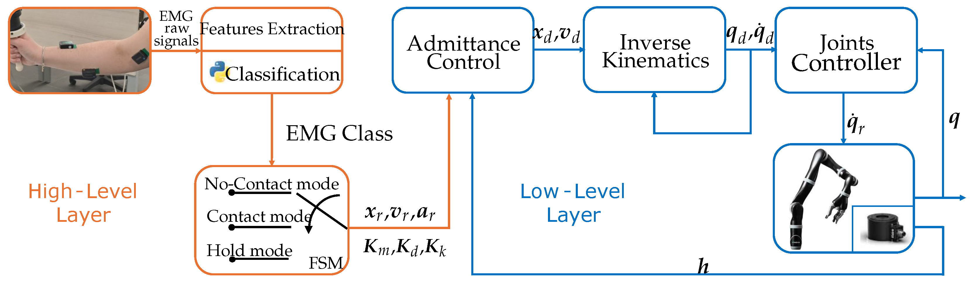
2. Materials and Methods

2.1. Shared Control Architecture

In the proposed architecture, three possible operational modes are taken into account:
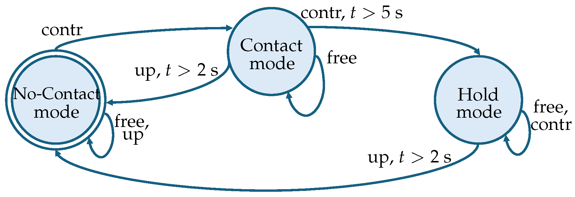
  • no-contact mode: hand-guidance of the end-effector in the free space to allow the operator to move the end-effector towards, e.g., a workpiece;
  • contact mode: hand-guidance of the end-effector while in contact with a stiff surface to allow performing operations like, e.g., carving, welding or drawing;
  • hold mode: in case of external disturbances, the manipulator is designed to elastically return the end-effector to a fixed position; this position is the same at which the switch to the hold mode occurs. This allows for the temporary relocation of the robot away from the point of interest, facilitating the placement of a workpiece that the robot is then responsible for maintaining in that position.
The proposed approach allows for the tackling of a wide range of common tasks in industrial scenarios through the combination of these three operational modes. To achieve this, the gains of the admittance controller of the manipulator are changed among three sets corresponding to each operational mode. A finite state machine algorithm handles the switching among these sets based on the movements or contractions of the operator’s arm, which are recognized through an EMG-based classifier.
Figure 1 shows the block diagram of the entire shared control architecture. The High-level layer includes all the functional blocks that address the generation of a certain set of admittance gains, while the Low-level layer includes all the blocks that concern the motion control of the manipulator. The raw EMG signals are used as the input to an SVM classifier that recognizes three possible classes of motions/contractions of the operator. The finite state machine algorithm receives this information and configures a set of admittance gains on the base of the operational mode; then, an admittance controller [39] outputs a desired trajectory for the end-effector, which is finally tracked by computing the needed joint velocity with an inverse kinematics algorithm [40]. In the following sections, details about all the functional blocks are given in a bottom-up order.

2.2. Low-Level Layer

The low-level layer implements the robot control algorithm and it is composed of three blocks: ( i ) the joints controller, ( i i ) the inverse kinematics controller and ( i i i ) the variable admittance controller. The variable admittance controller takes as input a certain reference trajectory for the end-effector and the readings of the wrench sensor mounted on the wrist of the manipulator, modifies it to comply with a desired variable dynamic behavior, and outputs a new desired trajectory for the end-effector. The inverse kinematics controller is responsible for computing the desired joint velocities that make the end-effector track the desired trajectory, while the joints controller generates the actual joint velocities command to the manipulator based on the joint encoder readings and on the inverse kinematics controller output.

2.2.1. Inverse Kinematics and Joints Controller

Considering a serial manipulator with n Degrees of Freedom (DOFs), the state of the system is described by the vector q = q 1 , q 2 , , q n T R n , which contains the joint positions. Define the vector that gathers the end-effector configuration as x = p T o T T R 7 , where p = p x , p y , p z T R 3 represents the coordinates of the end-effector expressed in the arm base frame, while o = o x , o y , o z , o w T R 4 is the quaternion that expresses the orientation of the end-effector with respect to the arm base frame. The velocity of the end-effector can be described by the vector v = p ˙ T ω T T R 6 , where p ˙ = p ˙ x , p ˙ y , p ˙ z T R 3 and ω = ω x , ω y , ω z T R 3 represent the end-effector linear and angular velocities, respectively. The differential relationship between the end-effector velocity and the joint velocity vector q ˙ = q ˙ 1 , q ˙ 2 , , q ˙ n T can be expressed as v = J q ˙ , where J R 6 × n is the robot Jacobian matrix.
Assuming a redundant manipulator, i.e., n > 6 , and the availability of a desired end-effector trajectory expressed as:
x d = p d o d R 7 v d = p ˙ d ω d R 6 a d = p ¨ d α d R 6 ,
where x d represents the desired position and quaternion, v d gathers the desired linear and angular velocities, and a d represents the desired linear and angular accelerations. The desired joint velocity that makes the end-effector track the desired trajectory can be computed by resorting to the Closed-Loop Inverse Kinematics (CLIK) algorithm:
q ˙ d = J ( v d + K ik x ˜ ) ,
where J is the Moore–Penrose pseudoinverse of the Jacobian matrix, K ik R 6 × 6 is a positive-definite matrix of gains, and x ˜ is the error vector, defined as:
x ˜ = p ˜ o ˜ = p d p ( q d ) o d 1 o ( q d ) R 6 ,
where p ˜ and o ˜ are the position and quaternion errors, respectively, and “⋆” is the quaternion product operator; q d is the vector of the desired joint position obtained by numerically integrating the desired joint velocity vector q ˙ d ; p ( q d ) and o ( q d ) are the position and orientation of the end-effector obtained by considering q d as joint positions in the direct kinematics computation.
Finally, the desired joint velocity vector is passed to the joints controller, which computes the actual command to send to the manipulator by resorting to a proportional controller including a feedforward action as:
q ˙ r = q ˙ d + K jc q ˜ ,
where K jc R n × n is a positive-definite matrix of gains and q ˜ = q d q is the joint position error computed with respect to the actual readings of the joint encoders.

2.2.2. Admittance Control

The admittance controller aims to assign virtual dynamics to the manipulator, characterized by a desired mass, damping, and stiffness. More in detail, assuming to have a wrench sensor mounted on the wrist of the manipulator and to have a certain reference trajectory for the end-effector, the desired end-effector trajectory must have the following dynamics:
K m a ˜ r , d + K d v ˜ r , d + K k x ˜ r , d = h ,
where the positive-definite matrices:
K m = K m p O 3 × 3 O 3 × 3 K m o
K d = K d p O 3 × 3 O 3 × 3 K d o
K k = K k p O 3 × 3 O 3 × 3 K k o ,
represent the virtual mass, damping, and stiffness, respectively, where the position K ( · ) p and orientation K ( · ) o gains are highlighted, h = f T μ T T R 6 is the vector stacking the linear force and moments measured by the wrench sensor, and:
x ˜ r , d = p ˜ r , d o ˜ r , d = p r p d o r 1 o d
v ˜ r , d = v r v d
a ˜ r , d = a r a d ,
are the operational space configuration, velocity and acceleration errors computed between the reference and the desired trajectories. The desired acceleration in output from the admittance controller can be computed by folding Equations (9)–(11) in Equation (5) and rearranging the terms, obtaining:
a d = K m 1 K m a r + K d v ˜ r , d + K k x ˜ r , d h .
The desired end-effector velocity v d and configuration x d to be tracked by the inverse kinematics controller in Equation (2) can then be obtained by numerical integration of the desired acceleration. It is worth noticing that the virtual mass, damping and stiffness can be varied, obtaining a variable admittance controller.
Each one of the operational modes listed in Section 2.1 has a corresponding set of admittance gains and potentially requested trajectory ( x r , v r , a r ) that adjust the robot’s behavior to successfully execute them. In detail, with reference to Equations (6)–(8), when in no-contact mode, the K k p gain is set to O 3 × 3 to allow the operator to freely move the end-effector, and K d p is set as K d p = diag { k d , low , k d , low , k d , low } , with low element k d , low to assure smooth teleoperation to the user; when in contact mode, the K k p gain is still set to O 3 × 3 , while K d p is set as K d p = diag { k d , low , k d , low , k d , high } with high element k d , high to guarantee both a stable contact with a stiff surface parallel to the x y plane of the arm base frame (e.g., a table where the workpieces are placed) and a smooth hand-guiding experience on the other two directions; finally, when in hold mode, the K k p gain is set to K k p = diag { k k , k k , k k } with k k > 0 and x r set to the end-effector position at the time of the state switch, while K d p is set as K d p = diag { k d , low , k d , low , k d , high } as in contact mode, to make the end-effector hold the position while being in contact with a stiff environment on the z coordinate and compliant with external forces coming from the other two directions. In all the possible states, the orientation of the end-effector is handled by letting the operator always adjust it with low damping, i.e., K k o = O 3 × 3 and K d o = diag { k d , low , k d , low , k d , low } . Finally, the virtual mass in Equation (6) is kept constant in all the states.

2.3. High-Level Layer

The high-level layer is composed of three main functional blocks: ( i ) the EMG sensors, ( i i ) the operator’s motion classifier, and ( i i i ) the finite state machine algorithm.

2.3.1. EMG Signal Processing and Classification

EMG signals are electrical signals produced by the muscles when they contract or relax. To detect these signals, surface or needle-based electrodes are used; in this work, non-invasive surface electrodes attached to the skin with adhesive are considered. The precise placement of these electrodes on the target muscle plays a crucial role, as the amplitude and frequency content of the EMG signals vary with electrode positioning relative to the muscle fibers. Before being processed, these signals need to be amplified, digitized and filtered to remove noise and processed to extract features to evaluate muscle functionality, activation or distinction between different types of contractions. In this work, EMG signals are used to detect muscle activity and patterns related to specific movements or actions. In order to achieve this objective, it is essential to utilize a signal processing classifier. A review of the literature on classifiers and preliminary tests performed on some of them, including those based on Random Forest, revealed that a Support Vector Machine (SVM) classifier was the most suitable for the purposes of this work.
The SVM classifier, which is a widely used supervised learning algorithm for classification tasks, receives a set of features extracted from the EMG signals segmented into time windows called epochs. In particular, three time-domain features commonly used for EMG signal classification [41] are extracted:
  • The Root Mean Square (RMS) can be used to evaluate muscle activity and fatigue; it is defined as:
    R M S = 1 N i = 1 N y i 2
  • The Mean Absolute Value (MAV) can be used to assess the intensity of muscle contraction. It’s definition is:
    M A V = 1 N i = 1 N y i
  • The Average Amplitude Change (AAC) provides information about fluctuations in muscle activity over a period of time and about the level of muscle activation during that period. It is useful for assessing muscle fatigue, tracking changes in muscle activity, and comparing muscle involvement during different activities or conditions. It can be computed as:
    A A C = 1 N i = 1 N y i + 1 y i
For all the features, y i is the i-th element of the vector y that contains the amplitudes of the EMG signals in a predefined epoch of 1s, and N is the number of elements contained in y.
To train the classifier, the SVM algorithm uses a data set consisting of feature vectors with associated class labels obtained with a predetermined acquisition procedure. The algorithm learns a decision boundary that maximally separates the different classes by finding an optimal hyperplane in the feature space.
Let x R d be a d-dimensional feature vector, and let z { 1 , 1 } be the class label in the binary case. The hyperplane that separates the classes can be represented as:
w ϕ ( x ) + b = 0 ,
where ϕ ( · ) is a function mapping the input data into the feature space, w is a vector of weights and b is the bias term. The parameters of the hyperplane that separate the classes most effectively can be obtained by solving the following Quadratic Programming (QP) problem:
min w , b , ζ 1 2 w T w + C i = 1 M ζ i subject to z i ( w T ϕ ( x i ) + b 1 ζ i i = 1 , 2 , , M
where M is the number of training samples, C > 0 is a regularization parameter and ζ i 0 are slack variables used to relax the constraint in the case of non-separable data. In the dual formulation of the SVM optimization problem, the decision function depends only on dot products between pairs of training samples in the feature space, i.e., x i T x j . These dot products are computed in practice via a kernel function K ( x i , x j ) . In this work, we use the Radial Basis Function (RBF) kernel:
K ( x i , x j ) = exp ( γ | | x i x j | | 2 )
where γ > 0 is a kernel parameter.
In the proposed scenario, the classifier is trained to discriminate among three classes: free, which includes all movements made by the operator moving the arm in various directions in the absence or with limited resisting forces; contraction, generated by the operator when he/she tightens his hand; and up, detected when the operator pushes upwards in the presence of resisting forces. Since we deal with multiclass classification (three classes), we employ a one-vs-rest strategy, in which three binary SVM classifiers are trained. Each classifier separates one class from the others, and during inference, the class corresponding to the classifier with the highest decision function output is selected.

2.3.2. Finite State Machine

The three classes in output from the SVM classifier are fed into a finite state machine algorithm to automatically switch among the three operational modes, as shown in Figure 2. In detail, the system starts in no-contact mode and stays in this state until the classifier recognizes the contraction class from the operator. When this happens, the state is changed to contact, giving in output a set of admittance gains that allows to safely put the end-effector in contact with a stiff environment without any unstable behavior. From this state, the operator can choose to switch back to no-contact mode, by triggering the up class for at least 2 s, or to go into hold mode by generating again the contraction class for at least 5 s. In this state, the end-effector holds the current position while the operator can still physically interact with it, and it remains in this state until the operator generates the up class for at least 2 s, switching back to no-contact mode.

3. Results

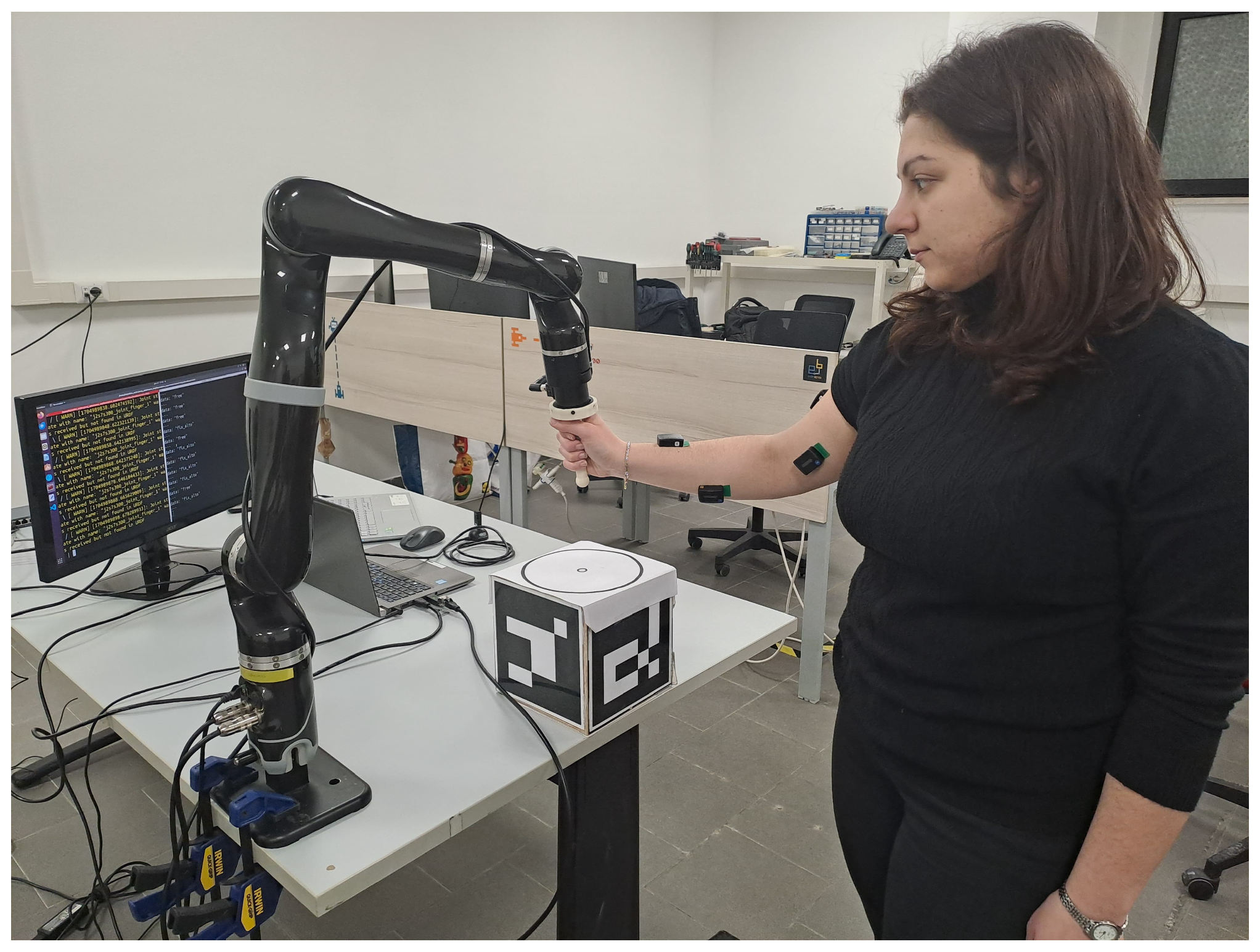
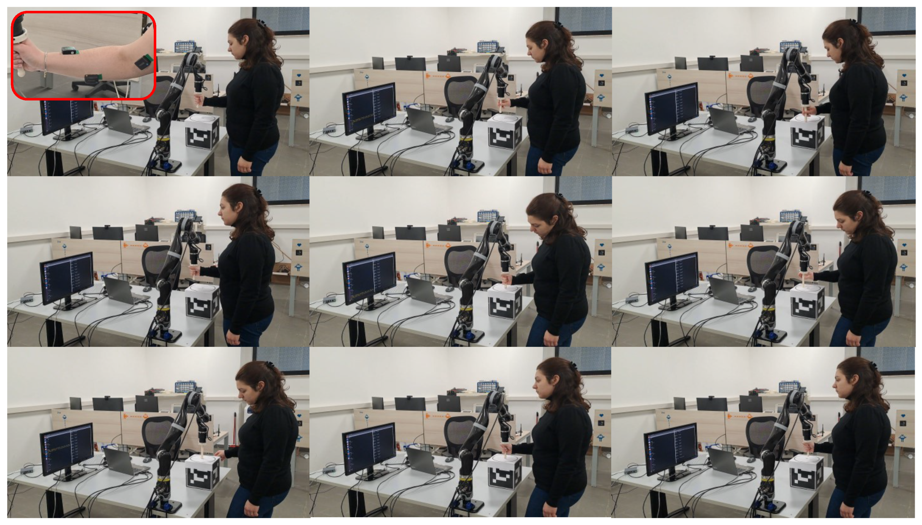
3.1. Experimental Setup

To validate the effectiveness of the proposed shared control architecture, experiments of human–robot co-manipulation tasks were conducted using a 7DOF Kinova Jaco2 manipulator (https://www.kinovarobotics.com/product/gen2-robots, accessed on 25 July 2025) equipped with a Bota Systems Rokubimini force/torque sensor (https://www.botasys.com/force-torque-sensors/rokubi, accessed on 25 July 2025). Four non-invasive Delsys Trigno Avanti (https://delsys.com/trigno-avanti/, accessed on 25 July 2025) sensors with a frequency of 1.78 kHz were also used; these are active sensors that already have a pan-integrated pre-amplification circuit that allows the reduction in input noise, such as parasitic voltages, due to capacitive couplings or the possible displacement of the electrodes. Following Seniam guidelines (http://seniam.org, accessed on 29 July 2025), sensors were placed on the dominant arm of the human operator, as much as possible in the center of the following muscles: the biceps and triceps brachii, flexor carpi radialis and extensor carpi ulnari muscles, as shown in Figure 3. The streaming of EMG data was performed through a Python v3.8 GUI on a Windows PC, while the control software and the SVM classifier, developed using Python and the Scikit-learn library [42], were implemented in the ROS (Robotic Operating System) framework running on Linux. To allow the two workstations to communicate, TCP/IP sockets were used.

3.2. Training and Test of the Classifier

As outlined in Section 2.3.1, the SVM classifier requires distinct datasets for training and testing. For each of the participants, a training set and a test set are acquired in two separate, sequential sessions conducted on the same day. This approach ensures a fair evaluation of the classifier’s performance on unseen data while minimizing variability caused by significant sensor displacement, as the electrodes are not detached between sessions.
The data acquisition protocol is designed to capture clear and representative signals for the three target classes (free, contraction, and up) by using two different robot behaviors. For the free class, the manipulator is set to a low-impedance, compliant mode, making it lightweight and easy to move. Operators are instructed to guide the end-effector for 5-second intervals in six directions (forward, backward, left, right, up, and down), while keeping their hand relaxed on the handle to avoid unintentional muscle contractions. For the contraction and up classes, the robot is rigid: this behavior is obtained by referring to a standard position controller and is used to gather data regarding the contraction (by tightening the hand on the end-effector handle for 5 s), and up (by pushing the end-effector upwards for 5 s) classes. Each action is followed by a 5-s rest period to prevent muscle fatigue and to create a clear separation between classes. For each training and test acquisition, the low-impedance phase lasted approximately three minutes, while the high-impedance phase lasted about one minute.
Both the training and test datasets obtained with the aforementioned acquisition procedure are processed by extracting the time domain features listed in Section 2.3.1 using Python for the classifier training. These three features are extracted for each of the four EMG sensors and transformed into a feature vector of 12 elements with an associated label class needed to train the classifier. The SVM model is trained using the hyperparameters in Table 1, and the classifier performance is evaluated using a confusion matrix for multi-class problems and class-wise metrics as Accuracy, Precision, Recall, and F1-score. Specifically, the confusion matrix rows represent the expected class distribution, while the columns represent the predicted distribution by the classifier. The Accuracy, Precision, Recall, and F1-score can be calculated for each class by converting the matrix to a one-vs-all matrix (to compute the performance index for binary classification) and computing the following indexes:
A = T P T P + T N + F P + F N
P = T P T P + F P
R = T P T P + F N
F 1 = T P T P + F N + F P 2 ,
where T P , T N , F P and F N are true positives/negatives and false positives/negatives taken from the binary problem confusion matrix, respectively, i.e., true positives and negatives represent the number of times the classifier correctly identified the positive/negative classes, while false positives and negatives are the values that were classified incorrectly. The accuracy measures how many instances were correctly classified, the precision measures the accuracy of the positive predictions, the recall is the ratio of positive instances that are correctly detected, and the F1 score is the harmonic mean of precision and recall. Then, global indexes are computed as the mean value of the performance indexes for each class.
In the online use of the classifier, the statistical mode of the predicted classes calculated over the last 1.5 s is sent to the finite state machine to increase the robustness in terms of misclassifications.

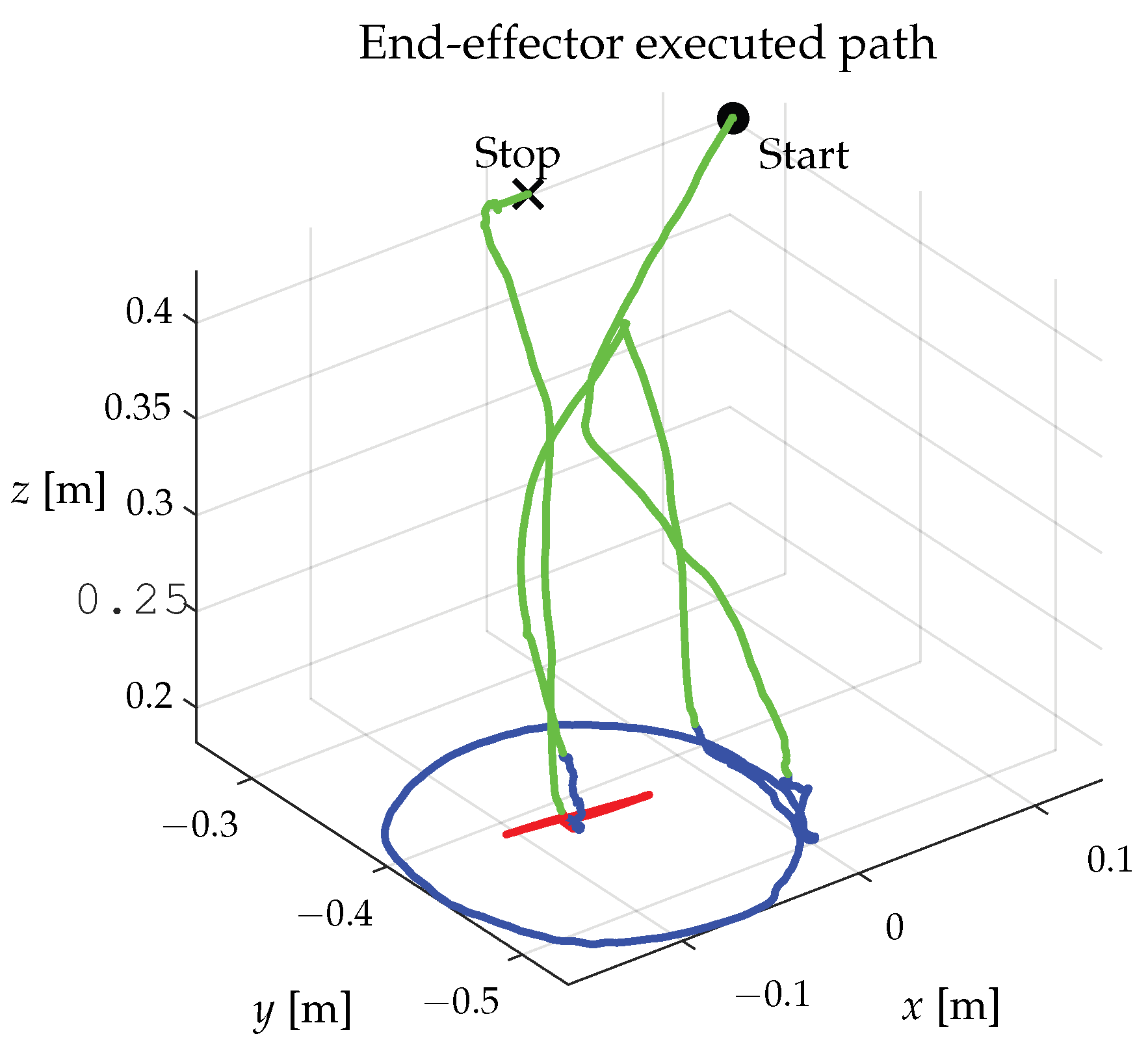
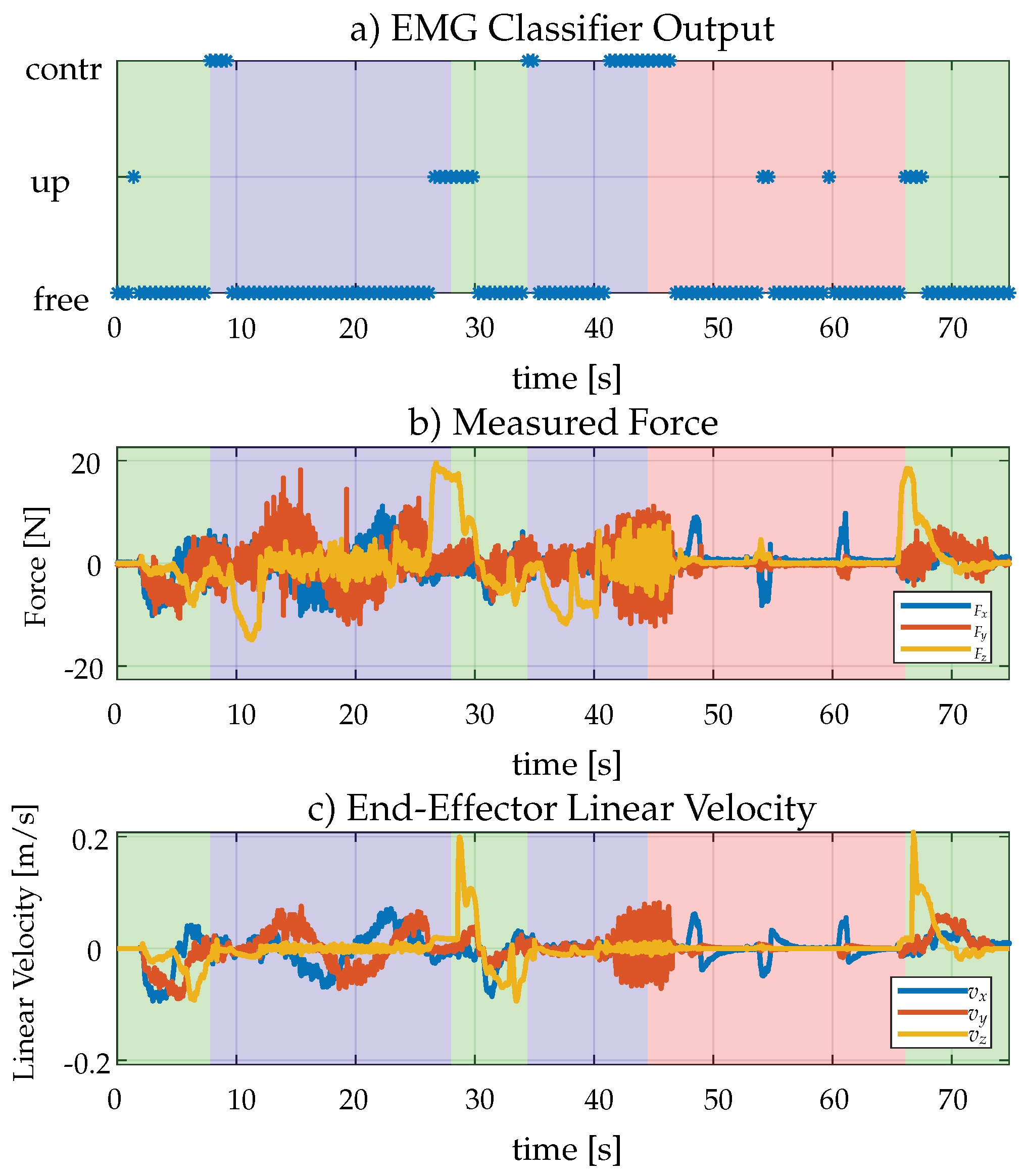
3.3. Experimental Results

To validate the overall architecture by triggering all the envisioned state transitions, the following representative sequence of operations characterized by several human–robot and human–environment interactions is requested to the user: ( i ) drive the end-effector closer to a surface using no-contact mode; ( i i ) switch to contact mode to enter in contact with the surface; ( i i i ) follow a predefined circular path drawn on the surface; ( i v ) lift the end-effector to switch to no-contact mode; ( v ) bring the end-effector in contact with the center of the circumference; ( v i ) change the robot operational mode to hold and push the end-effector to prove that it returns to the center; ( v i i ) lift the end-effector to return in no-contact mode again.
To test the generalization and the reproducibility of the approach, the designed experiment has been performed by a group of four participants (one female, aged 28, and three males, aged between 27 and 35), each of whom repeated it for 10 times. In accordance with the Declaration of Helsinki, all the participants provided signed informed consent, and the research protocol was approved by the Research Ethics Committee of the University of Cassino and Southern Lazio. The EMG sensors were placed on the same muscles of the dominant arm for all the subjects; however, considering the differences in the physical structure of the subjects, there were small displacements in the positioning of the sensors from one person to another to ensure that the sensors were placed as much as possible in the center of the considered muscles. Each of the four subjects performed the acquisition procedure described in Section 3.2 to obtain the training and test sets for classifier training. Subsequently, each subject obtained their trained SVM model, and the performance of the classifier was evaluated for each participant’s model using a confusion matrix and the global indices computed with it.
Table 1 shows the parameters for the controllers and the classifier used in the experiments, where all the admittance parameters were empirically determined in such a way that both the resonance phenomena can be dealt with and the co-manipulation can be made easier. A video showing some of the experimental runs of all participants is also provided at the following link (https://youtu.be/4YZ64SgFEro, accessed on 25 July 2025), and a selection of snapshots from the video of the experiment performed by Subject 1 is presented in Figure 4.
In the following, the results of the classifier performances and experimental execution are discussed. In particular, the confusion matrices of the SVM classifier trained for each subject are shown in Figure 5, while the global classifier indexes calculated using the formulas presented in Equation (16) through Equation (19) are shown in Table 2.
Accuracy scores range from 81.69 % to 91.40 % across the four subjects, indicating a strong overall classification performance, meaning that the majority of examples are classified correctly. Precision indexes show high values, from 82.16 % to 95.18 % , indicating few false positives, while the recall, which is generally good but lower than precision (from 76.61 % to 89.28 % ), suggests that the classifier is too conservative in predicting positive labels. Finally, F1 scores range from 78.11 % to 90.59 % , confirming a solid precision/recall balance with values close to accuracy. The numerical results demonstrate a reliable and accurate classification capability, although further analysis would be useful to improve recall by reducing false negatives.
As illustrated in Table 2, the performance indexes are, on average, higher for Subject 1 than for the other subjects, which can be attributed to the fact that she is more familiar with the procedure of acquiring datasets for training the classifier during interactions with the robot. This is due to the fact that she has carried out previous tests with the aforementioned setup, whereas the other subjects have merely followed the acquisition instructions without performing any preliminary tests. Despite this, the performance indexes are very high for all subjects and very close to the values obtained by Subject 1, who is to be considered the expert subject, and this attests that the adopted system is highly user-friendly, as also indicated in the NASA-TLX questionnaires (https://humansystems.arc.nasa.gov/groups/TLX/, accessed on 25 July 2025) completed by users. Indeed, the mean workload score across all dimensions for the task in question is approximately 34 % , indicating a relatively low overall workload. This suggests that participants generally found the task to be manageable and not onerous. Class-wise analysis of the confusion matrices reveals that the up class was more frequently misclassified across participants. This may be due to overlapping activation patterns between up and free, as both involve wide arm movements. Enhancing feature extraction or adding IMU-based motion data may reduce this confusion. On the other hand, it is clear that the contraction class presents the higher average accuracy among the subjects, indicating that the muscle activation patterns are different enough with respect to the other envisioned classes.
Figure 6 shows the path followed by the end-effector during one of the experiments performed by Subject 1, where the start and end points of the path are reported. Three different colors are used to highlight the path followed by the manipulator guided by the human operator, depending on the corresponding active operational mode: the paths executed in no-contact mode are highlighted in green; those corresponding to contact mode are highlighted in blue; finally, the path followed by the end-effector in hold mode is colored in red. It can be seen that the subject managed to complete the experiment without any difficulties by quickly changing the operational mode. Similar results were obtained by the other subjects involved, as shown in the video provided as Supplementary Materials for the present paper. Instead, Figure 7 shows the time evolution of the classifier output, the force measured by the F/T sensor, and the linear velocity of the manipulator’s end-effector. In particular, Figure 7 (top) shows the time evolution of the classifier output, which provides information about how it was able to distinguish among the three classes free, contraction and up during the experiment. Similarly to what was highlighted in the performed path, the colors green, blue, and red indicate the no-contact, contact, and hold modes, respectively. The output of the classifier determines the transition among the control modes, as demonstrated by the different colored areas; in fact, after the first 7 s in which the human is in free class, he/she generates contraction and FSM switches to no-contact mode, while when he/she generates up for at least 2 s as happens between 28 and 30 s or after 66 s, the mode returns to no-contact; even when the operator generates contraction for at least 5 s, as happens after 40 s, FSM switches to hold mode. The time evolution of the force (Figure 7 (middle)) and the end-effector linear velocity (Figure 7 (bottom)) are highlighted with the same colors according to the operational modes. To trigger the transition from no-contact to contact mode, i.e., from a low damping value to a high damping value, the operator needs to use the contraction class by contracting the hand around the end-effector. This causes oscillations in the force and velocity plots caused by the contraction itself, which also triggers the resonance phenomena, even if for a short period of time. This behavior is more evident when the operator generates contraction for at least 5 s to switch to hold mode; in fact, even if he/she is already in a control mode characterized by high damping, the high K d is set only along the z component to avoid resonance phenomena in the case of prolonged contact with the external environment, while low values are left on the x and y components to allow hand guidance and interaction with the operator in general.

4. Discussion and Limitations

This section presents an analysis of the experimental results and critically examines the current limitations of the proposed shared control architecture, while also outlining directions for future development.
The architecture presented in this work has been experimentally validated on a limited group of four participants, showing encouraging results in terms of both classifier performance and user experience. The Support Vector Machine (SVM) classifier achieved solid classification accuracy across all subjects, with F1-scores ranging from approximately 78% to 91%. This confirms that the use of EMG-based muscle contractions can effectively enable intuitive control mode switching during human–robot physical interaction. Moreover, the experiments demonstrated that the finite state machine (FSM) transitions were reliably triggered by the classifier outputs, enabling seamless switches between operational modes in real-time.
Nonetheless, several aspects warrant further discussion. The user study was conducted with only four individuals, including one expert and three novices, which limits the statistical robustness and generalizability of the results. While the proposed interface performed well across all participants, broader validation across a more diverse and larger user population will be necessary to draw definitive conclusions regarding its applicability in real-world collaborative settings.
Another important limitation lies in the training procedure. The classifier was trained individually for each user through a personalized acquisition session. While this guarantees high classification accuracy, it limits scalability and may be impractical in industrial contexts where fast setup and user independence are highly desirable. Future efforts will focus on implementing domain adaptation techniques or user-independent learning strategies to enhance the generality of the approach. The goal is to develop cross-user models that can generalize to new operators with little or no user-specific training data. Significant progress is being made in this area through the application of advanced machine learning, including deep learning frameworks that can learn user-invariant feature representations [43] and novel architectures like graph convolutional networks designed to model spatial-temporal EMG patterns across subjects [44]. However, the framework developed in this work is inherently modular and could be easily enhanced by incorporating the aforementioned techniques.
The set of EMG classes used in this work is intentionally limited to enable robust switching between three predefined operational modes. While sufficient for the demonstrated use case, this limited set restricts the complexity of tasks that can be performed. The extension to additional contraction classes, possibly combined with motion information from embedded inertial sensors, could allow proper control in more dynamic environments. Additionally, although detailed latency measurements were not collected, the overall system demonstrated real-time responsiveness. The 1.5 s windowed classifier mode output and FSM transitions showed minimal perceptible delay to users. Timing aspects such as classifier inference time, FSM transition delay, and controller actuation latency were not systematically measured. Such evaluation plays an important role in industrial deployment and will be prioritized in future studies.
Finally, it is important to highlight that the control strategy and classifier design are, in principle, system-independent. However, practical deployment on other platforms may require small adjustments to sensor placement, control parameters, or retraining of the classifier. It is also worth noting that the current system has not been directly compared against alternative control interfaces, such as button-based switching, voice commands, or gesture recognition using vision systems. Although these alternatives are briefly discussed in the introduction, a quantitative comparison would be valuable to justify the use of EMG signals. This comparison is left for future work, but is expected to further highlight the advantages of the proposed interface in terms of intuitiveness during physical interaction.

5. Conclusions

In this work, a shared control architecture is proposed that allows changing the admittance parameters of a manipulator in function of the EMG sensor readings in a human–robot co-manipulation scenario. A dedicated classifier recognizes the movements and contractions that the human operator performs, and this information is used to switch among three sets of admittance parameters to enable three different robot behaviors useful for performing several kinds of industrial applications. The architecture is validated on a Jaco2 robotic platform, making use of Trigno Avanti EMG sensors.
The approach has been validated on a limited group of four participants, supporting its feasibility in a controlled setting. The validation on multiple users confirms the robustness and user-friendliness of the architecture. The significance of this research is most evident in its direct practical value for real-world applications. By allowing the operator to modulate the robot’s behavior without interrupting the physical workflow, the system significantly enhances ergonomics and reduces cognitive load. The versatility offered by the defined no-contact, contact, and hold modes makes the system adaptable to a wide range of industrial scenarios, increasing the practical utility of collaborative robots.
Future works will be devoted to the exploitation of the IMUs (Inertial Measurement Units) included in the EMG sensors, merging this information with the muscle signals to be capable of classifying more complex human motions. Additionally, methods for anticipating and predicting human motions will also be investigated in order to make the robot able to proactively change its behavior depending on the human operator’s intentions, and the continuous time variation in the admittance parameters will be investigated for different scenarios and applications. Finally, efforts will also be devoted to exploring user-independent classifiers and learning techniques to extend the system’s generalization beyond user-specific training. This includes the integration of advanced cross-user learning models to drastically reduce or eliminate the calibration time for new operators [43,44].

Supplementary Materials

The following supporting information can be downloaded at: https://www.mdpi.com/article/10.3390/machines13080669/s1, Video of the experiment performed by subject S1.

Author Contributions

Conceptualization, F.A.; methodology, F.A. and P.D.L.; software, F.P. and P.D.L.; validation, F.P. and P.D.L.; formal analysis, F.A.; investigation, F.A.; resources, F.A.; data curation, F.P.; writing—original draft preparation, F.P. and P.D.L.; writing—review and editing, F.A. and P.D.L.; visualization, F.P. and P.D.L.; supervision, F.A.; project administration, F.A.; funding acquisition, F.A. All authors have read and agreed to the published version of the manuscript.

Funding

The research leading to these results has received funding from Project “COM3: COoperative Mobile Manipulators for Manufacturing” CUP: H53D23000610006, “COMET: Composable autonomy in Marine Environments” CUP: 2022TPSX25 and “MAXFISH: Multi agents systems and Max-Plus algebra theoretical frameworks for a robot-fish shoal modelling and control” CUP: 20225RYMJE, funded by EU in NextGenerationEU plan through the Italian “Bando Prin 2022-D.D. 104 del 02-02-2022” by MUR.

Institutional Review Board Statement

The research protocol was approved by the Research Ethics Committee of the University of Cassino and Southern Lazio.

Informed Consent Statement

In accordance with the Declaration of Helsinki, all the participants provided signed informed consent.

Data Availability Statement

The original contributions presented in this study are included in the article and Supplementary Materials. Further inquiries can be directed to the corresponding author.

Conflicts of Interest

The authors declare no conflicts of interest.

References

  1. Villani, V.; Pini, F.; Leali, F.; Secchi, C. Survey on human–robot collaboration in industrial settings: Safety, intuitive interfaces and applications. Mechatronics 2018, 55, 248–266. [Google Scholar] [CrossRef]
  2. Matheson, E.; Minto, R.; Zampieri, E.G.G.; Faccio, M.; Rosati, G. Human–Robot Collaboration in Manufacturing Applications: A Review. Robotics 2019, 8, 100. [Google Scholar] [CrossRef]
  3. Cherubini, A.; Passama, R.; Crosnier, A.; Lasnier, A.; Fraisse, P. Collaborative manufacturing with physical human–robot interaction. Robot.-Comput.-Integr. Manuf. 2016, 40, 1–13. [Google Scholar] [CrossRef]
  4. Sladić, S.; Lisjak, R.; Runko Luttenberger, L.; Musa, M. Trends and Progress in Collaborative Robot Applications. Politehnika 2021, 5, 32–37. [Google Scholar] [CrossRef]
  5. Sharifi, M.; Zakerimanesh, A.; Mehr, J.K.; Torabi, A.; Mushahwar, V.K.; Tavakoli, M. Impedance Variation and Learning Strategies in Human–Robot Interaction. IEEE Trans. Cybern. 2022, 52, 6462–6475. [Google Scholar] [CrossRef]
  6. Abu-Dakka, F.J.; Saveriano, M. Variable Impedance Control and Learning—A Review. Front. Robot. AI 2020, 7, 590681. [Google Scholar] [CrossRef] [PubMed]
  7. Abbink, D.A.; Carlson, T.; Mulder, M.; de Winter, J.C.F.; Aminravan, F.; Gibo, T.L.; Boer, E.R. A Topology of Shared Control Systems—Finding Common Ground in Diversity. IEEE Trans.-Hum.-Mach. Syst. 2018, 48, 509–525. [Google Scholar] [CrossRef]
  8. Kong, H.; Yang, C.; Li, G.; Dai, S.L. A sEMG-Based Shared Control System with No-Target Obstacle Avoidance for Omnidirectional Mobile Robots. IEEE Access 2020, 8, 26030–26040. [Google Scholar] [CrossRef]
  9. Selvaggio, M.; Cognetti, M.; Nikolaidis, S.; Ivaldi, S.; Siciliano, B. Autonomy in Physical Human-Robot Interaction: A Brief Survey. IEEE Robot. Autom. Lett. 2021, 6, 7989–7996. [Google Scholar] [CrossRef]
  10. Cacace, J.; Caccavale, R.; Finzi, A.; Lippiello, V. Variable Admittance Control based on Virtual Fixtures for Human-Robot Co-Manipulation. In Proceedings of the 2019 IEEE International Conference on Systems, Man and Cybernetics (SMC), Bari, Italy, 6–9 October 2019; pp. 1569–1574. [Google Scholar] [CrossRef]
  11. Zahedi, F.; Arnold, J.; Phillips, C.; Lee, H. Variable Damping Control for pHRI: Considering Stability, Agility, and Human Effort in Controlling Human Interactive Robots. IEEE Trans.-Hum.-Mach. Syst. 2021, 51, 504–513. [Google Scholar] [CrossRef]
  12. Ficuciello, F.; Villani, L.; Siciliano, B. Variable Impedance Control of Redundant Manipulators for Intuitive Human–Robot Physical Interaction. IEEE Trans. Robot. 2015, 31, 850–863. [Google Scholar] [CrossRef]
  13. Ferraguti, F.; Talignani Landi, C.; Sabattini, L.; Bonfe, M.; Fantuzzi, C.; Secchi, C. A variable admittance control strategy for stable physical human–robot interaction. Int. J. Robot. Res. 2019, 38, 747–765. [Google Scholar] [CrossRef]
  14. Wang, C.; Zhao, J. Based on human-like variable admittance control for human–robot collaborative motion. Robotica 2023, 41, 2155–2176. [Google Scholar] [CrossRef]
  15. Losey, D.P.; O’Malley, M.K. Trajectory Deformations From Physical Human–Robot Interaction. IEEE Trans. Robot. 2018, 34, 126–138. [Google Scholar] [CrossRef]
  16. Dimeas, F.; Aspragathos, N. Fuzzy learning variable admittance control for human-robot cooperation. In Proceedings of the 2014 IEEE/RSJ International Conference on Intelligent Robots and Systems, Chicago, IL, USA, 14–18 September 2014; pp. 4770–4775. [Google Scholar] [CrossRef]
  17. Grafakos, S.; Dimeas, F.; Aspragathos, N. Variable admittance control in pHRI using EMG-based arm muscles co-activation. In Proceedings of the 2016 IEEE International Conference on Systems, Man, and Cybernetics (SMC), Budapest, Hungary, 9–12 October 2016; pp. 1900–1905. [Google Scholar] [CrossRef]
  18. Adeola-Bello, Z.A.; Azlan, N.Z. Power Assist Rehabilitation Robot and Motion Intention Estimation. Int. J. Robot. Control Syst. 2022, 2, 297–316. [Google Scholar] [CrossRef]
  19. Gonzalez-Mendoza, A.; Quinones-Uriostegui, I.; Salazar-Cruz, S.; Perez Sanpablo, A.I.; López, R.; Lozano, R. Design and Implementation of a Rehabilitation Upper-limb Exoskeleton Robot Controlled by Cognitive and Physical Interfaces. J. Bionic Eng. 2022, 19, 1374–1391. [Google Scholar] [CrossRef] [PubMed]
  20. Aydin, Y.; Sirintuna, D.; Basdogan, C. Towards collaborative drilling with a cobot using admittance controller. Trans. Inst. Meas. Control 2021, 43, 1760–1773. [Google Scholar] [CrossRef]
  21. Bae, J.; Kim, K.; Huh, J.; Hong, D. Variable Admittance Control with Virtual Stiffness Guidance for Human–Robot Collaboration. IEEE Access 2020, 8, 117335–117346. [Google Scholar] [CrossRef]
  22. Li, J.; Li, G.; Chen, Z.; Li, J. A Novel EMG-Based Variable Impedance Control Method for a Tele-Operation System Under an Unstructured Environment. IEEE Access 2022, 10, 89509–89518. [Google Scholar] [CrossRef]
  23. Zeng, C.; Yang, C.; Cheng, H.; Li, Y.; Dai, S.L. Simultaneously Encoding Movement and sEMG-Based Stiffness for Robotic Skill Learning. IEEE Trans. Ind. Inform. 2021, 17, 1244–1252. [Google Scholar] [CrossRef]
  24. Tian, J.; Wang, H.; Zheng, S.; Ning, Y.; Zhang, X.; Niu, J.; Vladareanu, L. sEMG-Based Gain-Tuned Compliance Control for the Lower Limb Rehabilitation Robot during Passive Training. Sensors 2022, 22, 7890. [Google Scholar] [CrossRef] [PubMed]
  25. Chen, X.; Wang, N.; Cheng, H.; Yang, C. Neural Learning Enhanced Variable Admittance Control for Human–Robot Collaboration. IEEE Access 2020, 8, 25727–25737. [Google Scholar] [CrossRef]
  26. Zhuang, Y.; Yao, S.; Ma, C.; Song, R. Admittance Control Based on EMG-Driven Musculoskeletal Model Improves the Human–Robot Synchronization. IEEE Trans. Ind. Inform. 2019, 15, 1211–1218. [Google Scholar] [CrossRef]
  27. Wu, Q.; Chen, B.; Wu, H. Adaptive Admittance Control of an Upper Extremity Rehabilitation Robot with Neural-Network-Based Disturbance Observer. IEEE Access 2019, 7, 123807–123819. [Google Scholar] [CrossRef]
  28. Zhuang, Y.; Leng, Y.; Zhou, J.; Song, R.; Li, L.; Su, S.W. Voluntary Control of an Ankle Joint Exoskeleton by Able-Bodied Individuals and Stroke Survivors Using EMG-Based Admittance Control Scheme. IEEE Trans. Biomed. Eng. 2021, 68, 695–705. [Google Scholar] [CrossRef] [PubMed]
  29. Villa-Parra, A.; Delisle Rodriguez, D.; Botelho, T.; Villarejo Mayor, J.; Delis, A.; Carelli, R.; Frizera, A.; Freire, T. Control of a robotic knee exoskeleton for assistance and rehabilitation based on motion intention from sEMG. Res. Biomed. Eng. 2018, 34, 198–210. [Google Scholar] [CrossRef]
  30. Han, L.; Zhao, L.; Huang, Y.; Xu, W. Variable admittance control for safe physical human–robot interaction considering intuitive human intention. Mechatronics 2024, 97, 103098. [Google Scholar] [CrossRef]
  31. Hearst, M.A.; Dumais, S.T.; Osuna, E.; Platt, J.; Scholkopf, B. Support vector machines. IEEE Intell. Syst. Their Appl. 1998, 13, 18–28. [Google Scholar] [CrossRef]
  32. Gašpar, T.; Bevec, R.; Ridge, B.; Ude, A. Base Frame Calibration of a Reconfigurable Multi-robot System with Kinesthetic Guidance. In Advances in Service and Industrial Robotics; Aspragathos, N.A., Koustoumpardis, P.N., Moulianitis, V.C., Eds.; Springer: Cham, Switzerland, 2019; pp. 651–659. [Google Scholar] [CrossRef]
  33. Mielke, E.; Townsend, E.; Wingate, D.; Salmon, J.L.; Killpack, M.D. Human-robot planar co-manipulation of extended objects: Data-driven models and control from human-human dyads. Front. Neurorobotics 2024, 18, 1291694. [Google Scholar] [CrossRef]
  34. Musić, S.; Prattichizzo, D.; Hirche, S. Human-Robot Interaction Through Fingertip Haptic Devices for Cooperative Manipulation Tasks. In Proceedings of the 2019 28th IEEE International Conference on Robot and Human Interactive Communication (RO-MAN), New Delhi, India, 14–18 October 2019; pp. 1–7. [Google Scholar] [CrossRef]
  35. Du, G.; Zhang, P. A Markerless Human–Robot Interface Using Particle Filter and Kalman Filter for Dual Robots. IEEE Trans. Ind. Electron. 2015, 62, 2257–2264. [Google Scholar] [CrossRef]
  36. Maimon-Dror, R.O.; Fernandez-Quesada, J.; Zito, G.A.; Konnaris, C.; Dziemian, S.; Faisal, A.A. Towards free 3D end-point control for robotic-assisted human reaching using binocular eye tracking. In Proceedings of the 2017 International Conference on Rehabilitation Robotics (ICORR), London, UK, 17–20 July 2017; pp. 1049–1054. [Google Scholar] [CrossRef]
  37. Yacoub, A.; Flanagan, M.; Buerkle, A.; Bamber, T.; Ferreira, P.; Hubbard, E.M.; Lohse, N. Data-Driven Modelling of Human-Human Co-Manipulation Using Force and Muscle Surface Electromyogram Activities. Electronics 2021, 10, 1509. [Google Scholar] [CrossRef]
  38. Patriarca, F.; Di Lillo, P.; Arrichiello, F. EMG-based shared control framework for human-robot co-manipulation tasks. In Proceedings of the International Conference on Informatics in Control, Automation and Robotics, Porto, Portugal, 18–20 November 2024. [Google Scholar]
  39. Di Lillo, P.; Simetti, E.; Wanderlingh, F.; Casalino, G.; Antonelli, G. Underwater Intervention with Remote Supervision via Satellite Communication: Developed Control Architecture and Experimental Results Within the Dexrov Project. IEEE Trans. Control Syst. Technol. 2021, 29, 108–123. [Google Scholar] [CrossRef]
  40. Di Lillo, P.; Vito, D.D.; Antonelli, G. Merging Global and Local Planners: Real-Time Replanning Algorithm of Redundant Robots Within a Task-Priority Framework. IEEE Trans. Autom. Sci. Eng. 2023, 20, 1180–1193. [Google Scholar] [CrossRef]
  41. Manjunatha, H.; Jujjavarapu, S.S.; Esfahani, E.T. Classification of Motor Control Difficulty using EMG in Physical Human-Robot Interaction. In Proceedings of the 2020 IEEE International Conference on Systems, Man, and Cybernetics (SMC), Toronto, ON, Canada, 11–14 October 2020; pp. 2708–2713. [Google Scholar] [CrossRef]
  42. Kramer, O. Scikit-learn. In Machine Learning for Evolution Strategies; Springer: Cham, Switzerland, 2016; pp. 45–53. [Google Scholar]
  43. Campbell, E.; Phinyomark, A.; Scheme, E. Deep Cross-User Models Reduce the Training Burden in Myoelectric Control. Front. Neurosci. 2021, 15, 657958. [Google Scholar] [CrossRef] [PubMed]
  44. Xu, M.; Chen, X.; Ruan, Y.; Zhang, X. Cross-User Electromyography Pattern Recognition Based on a Novel Spatial-Temporal Graph Convolutional Network. IEEE Trans. Neural Syst. Rehabil. Eng. 2024, 32, 72–82. [Google Scholar] [CrossRef] [PubMed]
Figure 1. Proposed shared control architecture. The High-Level layer is responsible for the EMG signal acquisition and classification. Then, the recognized class is used into a finite-state machine algorithm that outputs a set of admittance gains. The Low-Level layer is responsible for the motion control of the manipulator and employs a variable admittance controller, an inverse kinematics algorithm and a joints controller.
Machines 13 00669 g001
Figure 2. Finite state machine. Starting from the no-contact mode, the FSM switches to a different control mode based on the class triggered by the human operator and the time it is maintained.
Machines 13 00669 g002
Figure 3. The scenario shows the experimental setup in which a human operator performs a co-manipulation task using a Jaco2 manipulator. On the dominant arm of the human operator, four Delsys Trigno Avanti EMG sensors are placed on the biceps and triceps brachii, flexor carpi radialis and extensor carpi ulnaris muscles.
Machines 13 00669 g003
Figure 4. The series of images displayed above illustrates one of the experiments conducted by Subject 1.
Machines 13 00669 g004
Figure 5. The confusion matrices obtained following the training of the classifier for all the participants: (a) Subject 1; (b) Subject 2; (c) Subject 3; (d) Subject 4.
Machines 13 00669 g005
Figure 6. The path followed by the manipulator’s end-effector in one of the experiments performed by the Subject 1. The path is highlighted with three colors based on the three operational modes: no-contact mode is marked in green, contact mode is highlighted in blue and hold mode is colored in red.
Machines 13 00669 g006
Figure 7. Results of one of the experiments of the Subject 1: (top) EMG classifier output, i.e., the statistical mode of the last 1.5 s of predicted classes; (middle) force measured by the F/T sensor; (bottom) end-effector linear velocity. The different colored areas on all graphs correspond to the three different control modes: green, blue and red represent the no-contact, contact, and hold modes, respectively.
Machines 13 00669 g007
Table 1. Experimental parameters used in the proposed architecture.
ParameterValueDescription
Control parameters
K ik diag { 20 I 3 , 15 I 3 } Inverse kinematics gain
K jc diag { 3 I 4 , 2 I 3 } Joints controller gain
k d , low 80Low-damping gain
k d , high 1000High-damping gain
k k 100Stiffness gain in hold mode
Classifier parameters
C1Regularization parameter
γscale1Parameter of a Gaussian Kernel
Kernel’RBF’Kernel used in the SVM Classifier
1 ’scale’ is a parameter that is automatically calculated as 1 divided by the product of the number of features and the variance of the feature vector.
Table 2. Table containing performance evaluation metrics.
SubjectAccuracy (%)Precision (%)Recall (%)F1 Score (%)
S191.4095.1887.5990.59
S281.6982.1678.9778.11
S390.8489.2289.2888.81
S484.1388.4176.6180.45
Disclaimer/Publisher’s Note: The statements, opinions and data contained in all publications are solely those of the individual author(s) and contributor(s) and not of MDPI and/or the editor(s). MDPI and/or the editor(s) disclaim responsibility for any injury to people or property resulting from any ideas, methods, instructions or products referred to in the content.

