1. Introduction
Flexure-based linear stages are frequently employed in precision mechanics to provide translational guiding functions with high precision. The lack of solid friction, clearance, backlash, wear, and their ability for monolithic manufacturing makes them extremely advantageous in micro- and nanopositioning systems [
1,
2,
3,
4], micro-electromechanical system (MEMS) sensors and actuators [
5], micromanipulation [
6,
7], metrology [
8,
9], and horological oscillators [
10]. It is often required that flexure linear guides describe a motion that is as close as possible to a pure translation. However, most designs exhibit parasitic shifts in addition to the intended rectilinear motion. For planar configurations, this defect is generally quantified by measuring the lateral in-plane deviation of the stage and its in-plane rotation. Most compliant stages, such as the well-known parallel leaf spring stage, have parasitic shifts in second order with respect to the primary displacement, due to the shortening of its flexures [
11]. These parasitic motions are frequently insignificant for small motion amplitudes, but they become a major source of error with larger deflections, degrading positioning accuracy.
Several solutions exist to minimize the parasitic shifts in flexure-based linear stages. One method is to substitute the ideal joints of straight-line linkages by flexure hinges [
8,
12,
13]. Such flexure-based mechanisms can typically exhibit a straightness error smaller than 200 nm over a 35 mm translational stroke [
8]. Another way to create flexure rectilinear stages is to compensate for the deflection shortening of the flexures with the motion of the rigid links [
14,
15]. It is also possible to symmetrize an existing flexure linear stage such that its platform is forced to translate rectilinearly [
16,
17]. However, such a structure is overconstrained, leading to substantial tensile stress in the flexures, which lowers its range of motion and results in highly nonlinear force–displacement characteristics. Conversely, linear stages can also be underconstrained for rectilinear motion of the platform [
1,
18]. While offering large strokes, it leads to low lateral stiffness and potentially uncontrolled vibration modes.
The support stiffness over the translational stiffness ratio of flexure-based rectilinear stages usually needs to be high [
19]. As a result, the rectilinear motion of the platform is less sensitive to external loads exerted on the mechanism. Since planar structures are considered in this paper, the term support stiffness mainly refers to the in-plane lateral translation stiffness and the in-plane rotation stiffness. The out-of-plane stiffness, being strongly dependent on the structure depth and other factors (e.g., the number and the distribution of parallel kinematic chains in the structure), is the topic of future work.
In this article, a novel family of rectilinear kinematic structures is presented. These mechanisms are constituted of
parallel kinematic chains, each based on three serial revolute joints (RRR), which are rotationally coupled at the base revolute joints to reduce the mobility of the platform to one degree of freedom (DOF) in translation (preprint [
20] and patent pending [
21]). Since this translation involves very low (or even zero, in some cases) parasitic shifts, we name the members of the family
-RRR rectilinear stages. Their planar kinematics can be implemented using flexures to create fully compliant rectilinear stages. The high support stiffness, resulting from the parallel kinematics, implies high positioning accuracy in the presence of loads in their support directions and facilitates their dynamic control (high undesired eigenfrequencies). Both large strokes and highly linear force–displacement characteristics can be accomplished, because these structures can be made kinematically isostatic (exact constrained). Fortunately, the mechanisms can be compact and symmetrical to reduce possible sensitivity to temperature gradients [
22].
The main contributions of this work are summarized as follows:
Presentation of a new family of flexure-based mechanisms that achieve rectilinear motion with minimum parasitic shifts.
Performance study based on Finite Element Method (FEM) models to evaluate and compare different configurations within the family, in terms of motion range, parasitic motion, and support stiffness.
Validation of the models by experiments performed on a mesoscale plastic mockup of one of the design variants.
Investigation of integrating buckled beams in a 4-RRR rectilinear stage silicon prototype to effectively reduce its stiffness along the primary degree of freedom without compromising support stiffness.
The proposed designs offer an innovative solution to the limitations of existing flexure-based mechanisms, paving the way for improved performance in high-precision applications that require large strokes and minimized parasitic shift properties. It is also possible to use such stages in series to create a multi-degrees-of-freedom stage with minimum cross-axis coupling errors [
12], or redundant dual-stages with minimal interference behavior [
23].
Section 2 and
Section 3 present the kinematics of this new family of mechanisms and their flexure implementations, respectively. An analytical model is derived in
Section 4 to help in designing such flexure rectilinear mechanisms.
Section 5 introduces the FEM modeling used to compare the performance of the selected design variants within the family.
Section 6 presents the experimental method carried out on a plastic mockup to verify the parasitic motions and the stiffness characteristics. The analytical, FEM, and experimental results are compared in
Section 7. An application example is described in
Section 8, where buckling beams are incorporated into a silicon prototype for a reduction in the translational stiffness. Concluding remarks and future directions for this research are provided in
Section 9.
2. Kinematics of the n-RRR Rectilinear Stage Family
The rectilinear stages presented in this article are based on -RRR planar parallel manipulators with kinematic chain coupling to reduce the mobility of the platform to 1 DOF in translation. Depending on the number of kinematic chains , the individual architectures are then given names such as TRIOSTAGE ( and QUADRISTAGE (. Based on these particular cases, it is straightforward to conceive other rectilinear stages of the same family having other values of . Depending on the linkages used to couple kinematic chains, the order of the parasitic shift with respect to the primary displacement is modified. We consider three types of couplers as follows: parallelogram linkage (Type I), Watt’s linkage (Type II), and Kempe’s Reversor linkage (Type III). Note that it is possible to conceive rectilinear stages having different types of couplers at once; we call them hybrid rectilinear stages. The name of each mechanism topology is based on the type of coupler (PARA-, WATT-, and KEMPE-) and the number of kinematic chains (TRIO- and QUADRI-).
In
Section 2.1, the kinematics of the rectilinear stage family are discussed on the basis of the generic Type 1 TRIOSTAGE. In
Section 2.2, several design variants are presented. In
Section 2.3, a selection of particular designs for further analysis is presented.
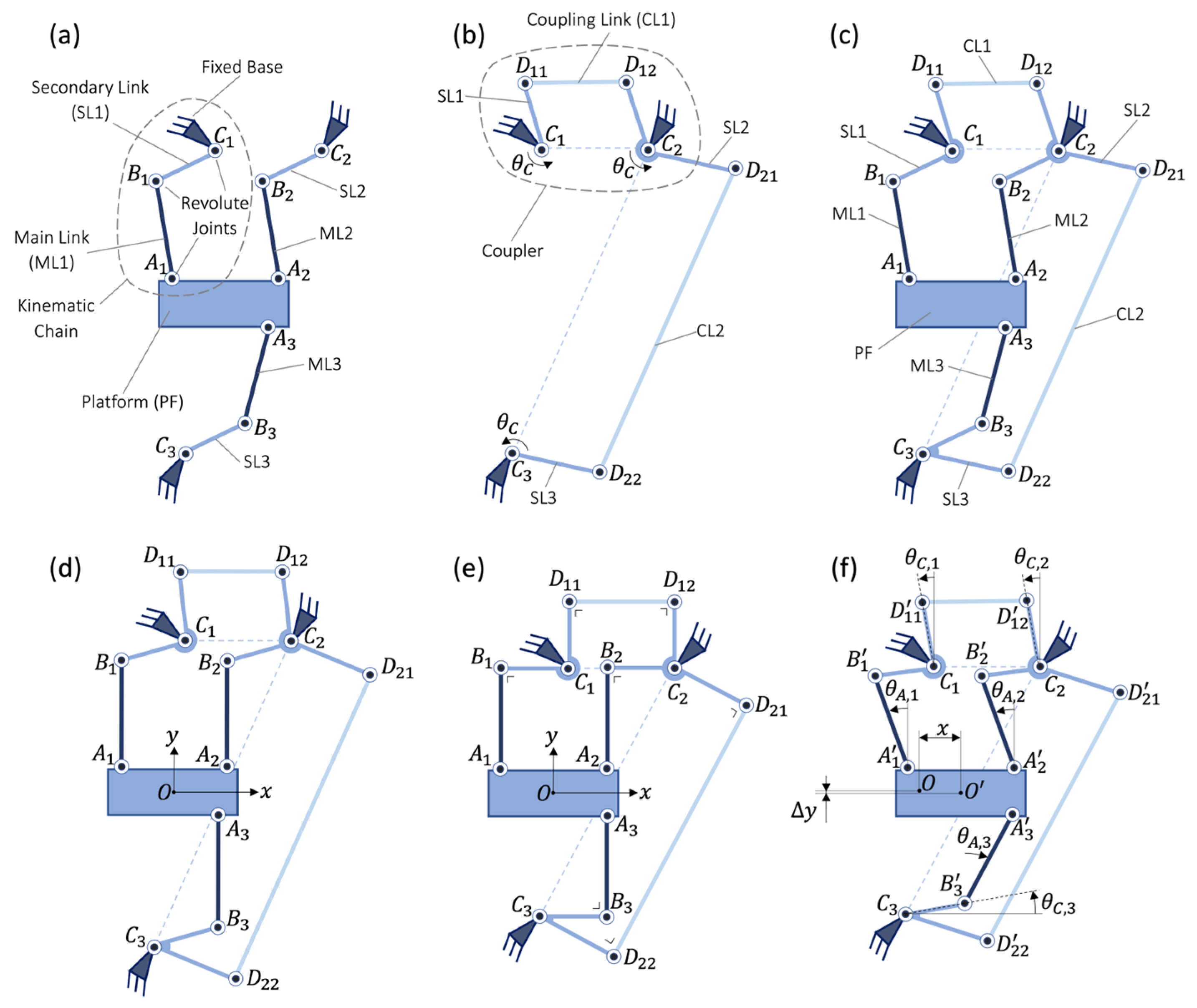
2.1. Generic Type I TRIOSTAGE
2.1.1. Topology
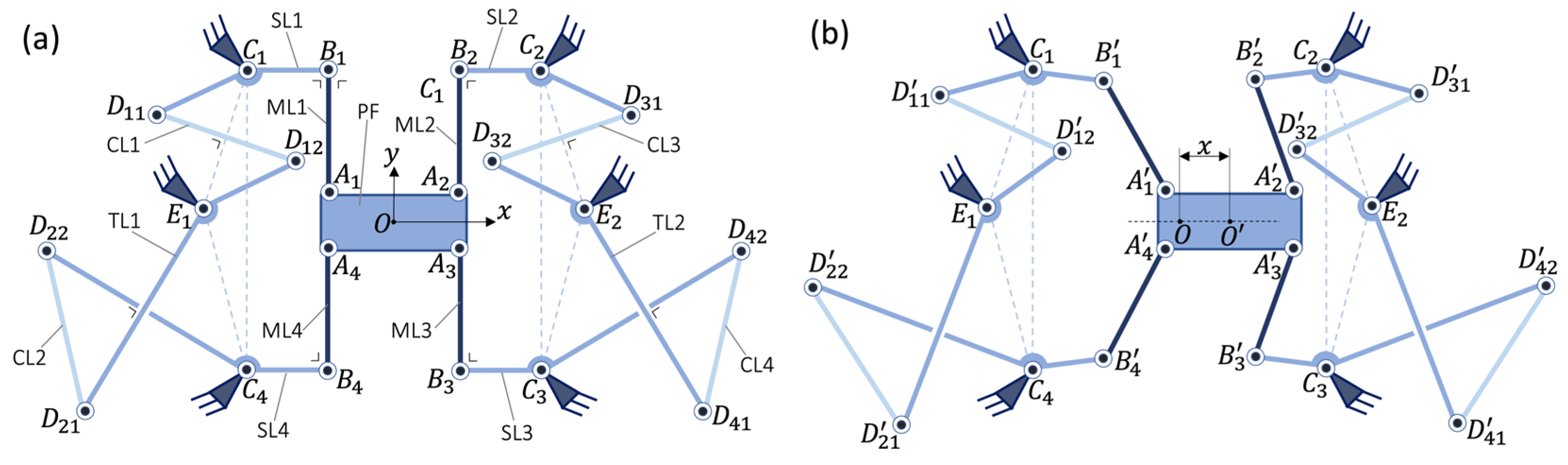
A Type I TRIOSTAGE is presented in
Figure 1. It is composed of a mobile platform (PF) connected via three main revolute joints (
,
and
) to three main rigid links (ML1, ML2, and ML3). These three main links are connected via three intermediate revolute joints (
,
and
) to three secondary rigid links (SL1, SL2, and SL3), respectively. The three secondary links are connected to the fixed base via three secondary revolute joints (
,
and
). The secondary links SL1 and SL2 are connected to each other via a rigid coupling link CL1 and two coupling revolute joints
and
. The secondary links SL2 and SL3 are connected to each other via a rigid coupling link CL2 and two coupling revolute joints
and
.
Remark 1. The mobile platform (PF) and the fixed base are functionally interchangeable parts in all rectilinear stage mechanisms, which means that switching them does not affect the mechanism’s kinematic characteristics.
Remark 2. A Type I TRIOSTAGE has exactly the same topology as a Type I TRIOVOT (described in [24]). However, since the geometric conditions are different (Section 2.1.2), a Type I TRIOSTAGE is a rectilinear stage with near-zero parasitic shift and a Type I TRIOVOT is a pivot with zero parasitic shift. 2.1.2. Geometric Conditions
Type I TRIOSTAGE is defined by the topology given in
Section 2.1.1 complying with the following conditions:
Condition 1. In neutral position, the triangles and are congruent and have the same orientation.
Condition 2. In neutral position, the triangles and are congruent and rotated 180 degrees with respect to each other.
Condition 3. The quadrilaterals and are parallelograms.
2.1.3. Kinematic Properties
The -axis is defined as the axis perpendicular to the line segment that passes by the center of the line segment when the linear stage is in neutral position. The -axis is perpendicular to the -axis and passes by the center of the line segment when the linear stage is in neutral position. The center is the intersection of the axes and . The center is the point lying on the platform where the rectilinear stage is deformed coinciding with in neutral position. The projection of the line segment on the -axis is called the parasitic translation ().
If Conditions 1 to 3 are respected, Type I TRIOSTAGE has a single DOF which is a primary translation of the mobile platform along in addition to a small parasitic translation along . The platform has no in-plane parasitic rotation because remains a translate of , even if the mechanism is deformed, thanks to the coupling of kinematic chains 1 and 2.
It is remarkable to note that, as long as singularities are avoided, the mechanism is isostatic, i.e., not under- or overconstrained. Indeed, when the couplers (
Figure 1b) are attached to the 3-RRR planar parallel mechanism (
Figure 1a), the platform mobility decreases from 3 DOF (all in-plane DOF) to 1 DOF in translation along
(
Figure 1c). Each coupler independently blocks 1 DOF of the platform as follows: CL1 prevents the in-plane rotation and CL2 limits the translation along
. Advantageously, ML1, ML2, and ML3 extend perpendicular to the
-axis when the platform is in a neutral position, which maximizes the in-plane support stiffness of the stage.
2.1.4. Particular Cases
Some auxiliary geometric conditions can be added to improve the performance of Type I TRIOSTAGE as follows:
Condition 4. In neutral position, the lines drawn by and (respectively, and , and and ) are orthogonal. Advantage: When the platform is translated in the vicinity of the neutral position, the rotation amplitude of the secondary links tends to zero. This minimizes the lateral shift and the stiffness constant along of the mechanism when based on flexures.
Condition 5. In neutral position, the line segment is orthogonal to as well as to (respectively, is orthogonal to as well as to ). Advantage: The forces transmitted through the coupling links are minimized. This maximizes the support stiffness along and around the out-of-plane direction of the platform when the mechanism is based on flexures.
Condition 6. In neutral position, the line segment is parallel to , and is parallel to . Advantage: This enables the transmission of forces between ML1, ML2 and ML3 through the platform, with minimized distance.
A Type I TRIOSTAGE satisfying all the listed conditions (1 to 6) is shown in neutral and deformed positions, respectively, in
Figure 1e,f. When the platform is displaced along the
-direction, it causes a rotation of secondary links in an anticlockwise direction about their respective frame hinges with an equal angle
, thanks to the angular coupling of the parallelogram linkages (see
Figure 1b). In that case, there is no parasitic rotation in the
-plane since main links ML1 and ML2 rotate equally (
). However, the platform has a slight parasitic translation of the platform parallel to the
-axis, because ML2 and ML3 do not rotate equally (
). Geometrically, the amplitude of this parasitic translation is of fifth order with respect to the primary displacement
:
where
and
are the lengths of the line segments
and
, respectively, for all kinematic chains
. For comparison, a classic parallel leaf spring stage has a second-order parasitic translation, i.e.,
[
11].
2.2. Design Variants
Design alternatives to Type I TRIOSTAGE, where the topology or Conditions 1 to 3 are modified (e.g., supernumerary kinematic chains or coupling links), are presented for their additional benefits. The considered design variants are listed below, with their respective advantages and potential drawbacks:
Mirrored kinematic chain: Condition 2 is modified such that triangles and are congruent and are mirror symmetric with respect to the -axis.
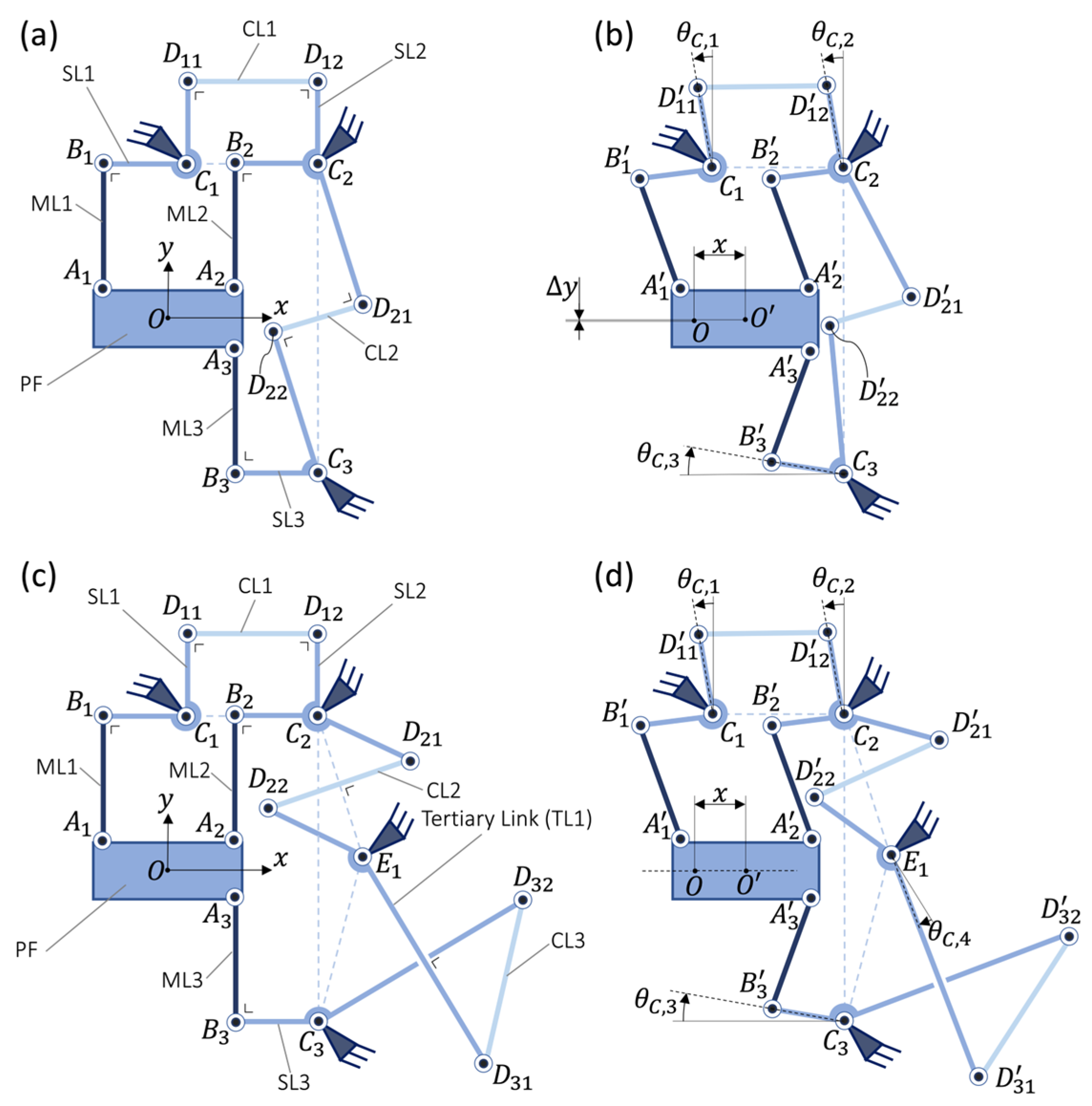
Watt’s linkage coupler (Type II): In order to couple two mirrored kinematic chains, Condition 3 is modified as follows: the coupler formed by
is replaced by a Watt linkage, as shown in
Figure 2a,b. This fulfills the coupling of mirrored secondary links SL2 and SL3, forcing them to rotate with approximately equal angle magnitude but in opposite directions. If Condition 5 is satisfied, a Watt linkage coupler transmits the angular displacement between
and
with a fourth-order error about the neutral position of the mechanism:
where
is the length of the line segments
and
, and
is the length of the line segments
. This transmission defect leads to a lateral shift
of the platform. If, in addition, Condition 4 is respected, this parasitic shift is minimized and of eighth order with respect to
:
It can be seen that the order of is greatly reduced in comparison to a Type I TRIOSTAGE (Equation (1)). Note also that the advantage of transmitting minimized forces through the coupling links is preserved with Condition 5.
Kempe’s linkage coupler (Type III): Instead of using Watt’s linkage (see kinematic variant above), it is possible to employ a linkage called Kempe’s Reversor [
25] to couple two mirrored kinematic chains. This linkage, which is composed of two antiparallelograms
and
(as shown in
Figure 2c,d), can perfectly reverse the angular displacement of two pivot joints. Since
, the platform has no parasitic shift in rotation nor in translation (i.e.,
). This mechanism is thus a novel perfect straight-line rectilinear mechanism. Condition 5 is modified for Kempe’s linkage couplers as follows: in neutral position,
and
form squares in order to minimize the forces transmitted through the coupling links.
Supernumerary kinematic chains: The number of kinematic chains ( in the case of TRIOSTAGE structures) can be increased (e.g., for QUADRISTAGE structures). This can lead to increased load capacity in out-of-plane directions, but also an increased mechanism footprint.
Supernumerary coupling links: The number of coupling links ( in the case of Type I TRIOSTAGE) can be increased. Note that additional coupling links (i.e., ) induce overconstraints but lead to increased load capacity in in-plane directions. In general, at least two couplers must be used, and at least one of these must connect two 180° rotated or two mirrored kinematic chains (in order to block the degree of freedom in the direction).
2.3. Selected n-RRR Rectilinear Stage Architectures
Based on the generic Type I TRIOSTAGE (
Section 2.1) and its kinematic variants (
Section 2.2), we select four
-RRR rectilinear stage structures of interest. The performance will be compared when embodied with flexures (
Section 3).
We first consider a Type I TRIOSTAGE where Conditions 1 to 6 are fulfilled (
Figure 1e,f), which we name PARA-TRIOSTAGE. Then, we design QUADRISTAGE mechanisms (i.e., 4-RRR rectilinear stages) with two symmetrical couplers arranged in pairs. The three different types of couplers are tested, and we call the respective mechanisms as follows: PARA-QUADRISTAGE (based on Type I couplers), WATT-QUADRISTAGE (based on Type II couplers), and KEMPE-QUADRISTAGE (based on Type III couplers). These arrangements enable symmetrical behavior in both translational directions, which is not the case for any TRIOSTAGE. To further reduce the lateral shift
at the platform center
, reflection and central symmetries are selected if coupled kinematic chains involve odd and even orders of lateral shift, respectively. The advantages of such symmetry are discussed for each mechanism in
Section 2.3.1,
Section 2.3.2 and
Section 2.3.3.
In this selection, we do not consider -RRR rectilinear stages with more than = 4 kinematic chains for reasons of compactness.
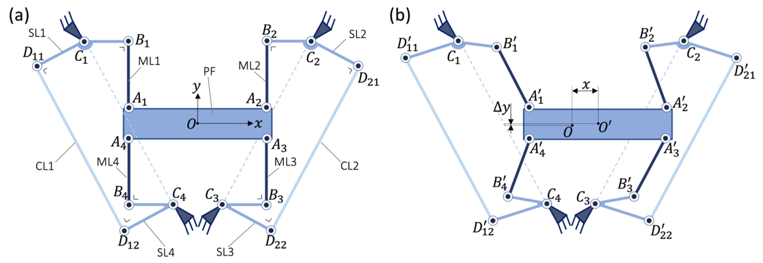
2.3.1. PARA-QUADRISTAGE
The PARA-QUADRISTAGE (
Figure 3) satisfies Conditions 2 to 6 for all its kinematic chains and couplers. Furthermore, its two couplers are arranged with a reflection symmetry around the
-axis in neutral position, see
Figure 3a. This kind of symmetry allows the lateral shift
, which is of fifth order at the center points of
and
(Equation (1)), to be averaged at the center
such that the order of the lateral shift is increased. However, the counterpart is that the platform has a fifth-order parasitic rotation compared to PARA-TRIOSTAGE which has no parasitic rotation.
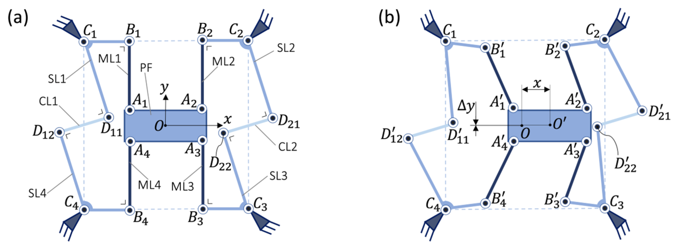
2.3.2. WATT-QUADRISTAGE
Conditions 2 to 6 are respected for all the kinematic chains and couplers of the WATT-QUADRISTAGE (where Condition 3 is changed to comply with Type II couplers). Its two couplers are arranged with a central symmetry around
in neutral position; see
Figure 4. This kind of symmetry allows the lateral shift, which is of eighth order at the center points of
and
(Equation (3)), to be averaged at the center
to increase the order of the lateral shift. However, the platform exhibits an eight-order parasitic rotation in comparison to the hybrid Type I+II TRIOSTAGE (
Figure 2a) which has no parasitic rotation.
2.3.3. KEMPE-QUADRISTAGE
Conditions 2 to 6 are respected for all the kinematic chains and couplers of the KEMPE-QUADRISTAGE (where Condition 3 and 5 are modified to comply with Type III couplers). Since Type III couplers do not result in parasitic shift in the platform, the two couplers can be arranged with either reflection or central symmetries in neutral position, without altering the rectilinear motion. It is chosen that the two couplers are mirror symmetric about the
-axis to reduce the size of the mechanism; see
Figure 5. As for the Type I + III TRIOSTAGE (
Figure 2c), the KEMPE-QUADRISTAGE is a perfect straight-line rectilinear mechanism.
3. Flexure Implementation
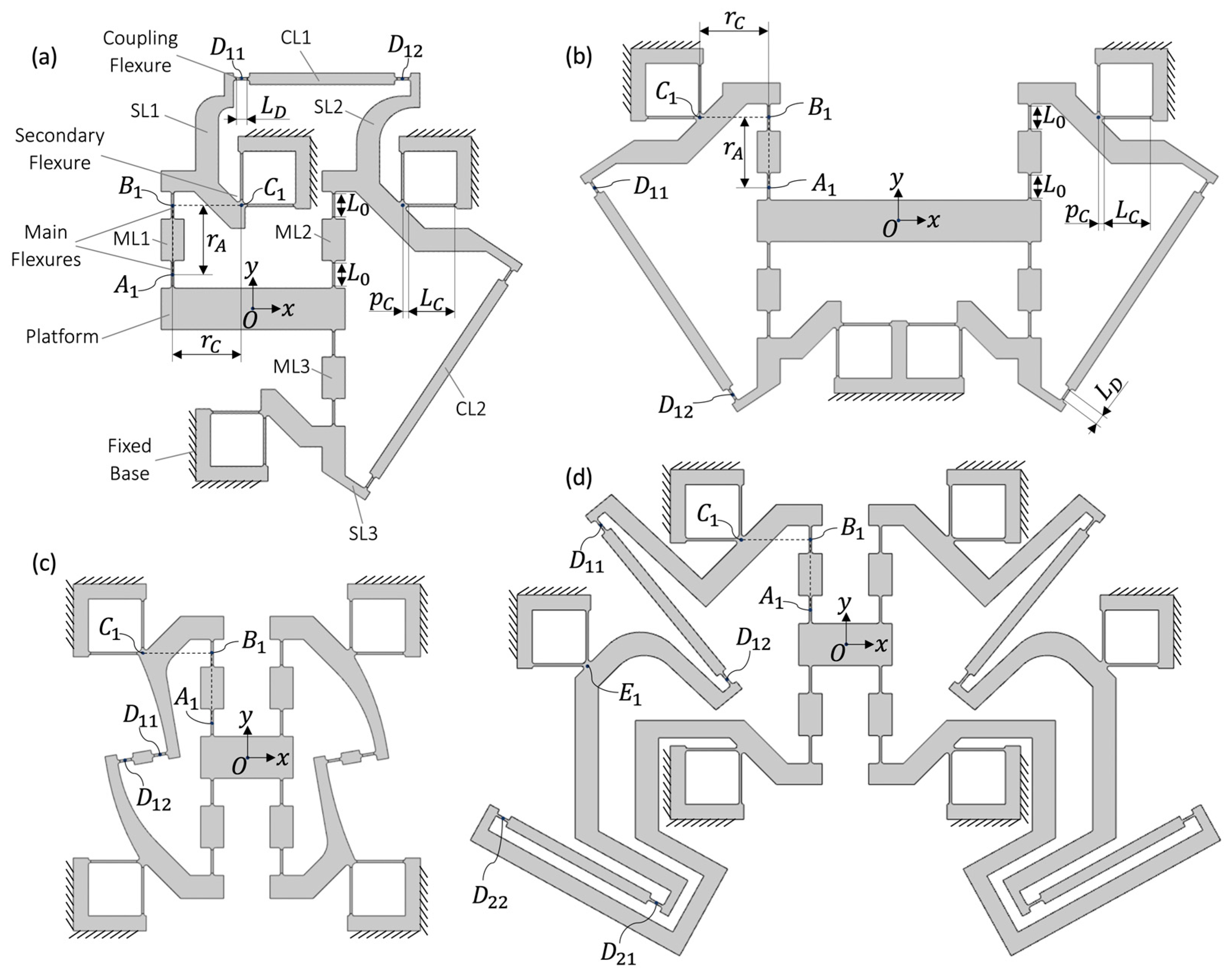
In this section, we provide planar monolithic flexure implementations of the PARA-TRIOSTAGE, PARA-QUADRISTAGE, WATT-QUADRISTAGE, and KEMPE-QUADRISTAGE (
Figure 6). For all these rectilinear stages, the revolute joints at the extremities of the main links are each implemented by leaf springs, called main flexures. The base revolute joints are implemented by Remote Center of Compliance (RCC) pivots, called secondary flexures. The revolute joints at the extremities of the coupling links are replaced by leaf springs, called coupling flexures. The center of each leaf spring and the rotation axis of each RCC pivot coincide with the point location of their respective kinematic revolute joints; see
Figure 6. The distances
,
,
,
, and
all geometrically retain the same definition. The other rigid parts of the flexure pivots keep the same name as their corresponding kinematic architectures illustrated in
Figure 1,
Figure 3,
Figure 4 and
Figure 5. Filets are placed at the extremities of each flexure to mitigate stress concentration.
4. Analytical Model
This section presents models for the flexure-based versions of the selected
-RRR rectilinear stages for the purpose of designing such structures. The models will be validated in
Section 7 by comparing the results with FEM and experimental data. For the calculations, we consider that all the kinematic chains of a given rectilinear stage have the same dimensions. To further simplify the design, the main flexures have the same length
and thickness
. The platform is supposed to move rectilinearly along the
-axis and sufficiently close to its neutral position. In this case, the rotation angle
of the secondary flexures (and conversely the coupling flexures) can be assumed equal for all the kinematic chains. We compute the rotation magnitude
with respect to the displacement
in
Section 4.1. Then the translational stiffness and the admissible stroke of the platform are expressed in
Section 4.2 and
Section 4.3, respectively.
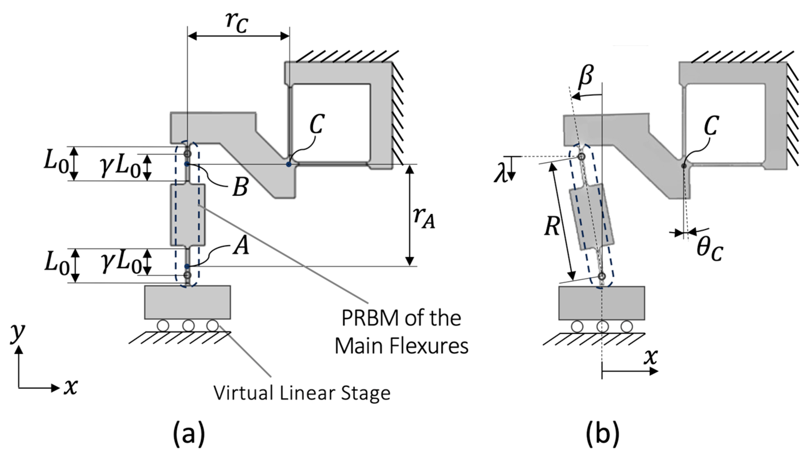
4.1. Deflection of the Secondary and Coupling Flexures
The rotation angle
is related to the axial shortening
(directed along the
-axis) of the main flexures and the main links; see
Figure 7. For small deformations, we have the following approximation:
The value of
is calculated based on a pseudo-rigid-body model (PRBM) [
26] of the main flexures (
Figure 7). As it is assumed that the instant rotation axis of each flexure lies at their center, we select a PRBM radius factor of
[
27], Equation (35.2). The length of the rigid body is
. When the platform deflects by a displacement
(
Figure 7b), the rigid body rotates by an angle
, leading to the following shortening:
4.2. Translational Stiffness
When Condition 4 is respected, the stiffness constant
is independent of the stiffness of the secondary and coupling flexures. Indeed, the latter rotate at second order with respect to the translation displacement
; see Equations (4) and (5). It can then be noticed that the deformation of each main flexure largely matches that of a so-called four prismatic notch hinge stage [
11]. In this case, the translational stiffness of the latter mechanism (derived in [
11], Equation (4.70)) is used to evaluate the
-axis stiffness constant
of an
-RRR rectilinear stage:
where
,
,
is Young’s modulus, and
is the out-of-plane depth of the stage.
4.3. Translational Stroke
Since the deformation of the secondary and coupling flexures is significantly smaller than that of the main flexures, it is assumed that the maximum internal stress
is located in the main flexures. This assumption can be verified analytically (using Equations (4) and (5)), or through FEM modeling (which is carried out in
Section 5). In this case, the admissible stroke also corresponds to that of a four prismatic notch hinge stage, whose formula is provided by [
11], Equation (4.71) as:
where
is the maximum engineering tolerated value of stress that can be applied to the material (e.g., the yield or fatigue strength) while accounting for a safety factor. Likewise, the maximum stress in the mechanism for a given displacement
can be determined by simply inverting Equation (7):
5. Finite Element Models for Performance Comparison
In order to evaluate and compare the performance of the selected flexure rectilinear stages (i.e., the PARA-TRIOSTAGE, the PARA-QUADRISTAGE, the WATT-QUADRISTAGE, and the KEMPE-QUADRISTAGE), we perform FEM simulations. While the optimal design is strongly application-dependent, to provide a basis for comparison of the selected structures, the following parameters are chosen or optimized:
The rectilinear stages are monolithic and made of the same material: polyoxymethylene (POM) having Young’s modulus of 3 GPa.
The out-of-plane width of the mechanisms is 5 mm.
The thickness of all flexures is 1 mm.
All the kinematic chains are identical (the dimensions are given in
Table 1).
The coupling flexures have length = 5 mm.
The length of the coupling links depends on the ideal kinematics of the mechanism.
The platform is a rectangle with a height (along ) equal to 20 mm.
The mechanism size is minimized while avoiding collision between the different parts of the mechanism.
To evaluate the characteristics of the different rectilinear stage mechanisms, three 2D nonlinear static FEM studies were carried out using the Solid Mechanics module of COMSOL Multiphysics 6.2:
Study 1: A displacement is applied along
to the platform while the mechanism base is fixed (
Figure 8). The displacement
is varied from −6 mm to 6 mm with equal steps of 0.5 mm. The stiffness constant
is evaluated as the linear term of a fifth degree polynomial fitted to the force–displacement FEM data along the
-direction. The polynomial degree is selected to avoid over- and underfitting the data. During this study, we also evaluate the maximum von Mises stress
and the parasitic shifts
and
along the lateral axis
and around the out-of-plane axis
, respectively. Note that the reference frame (
,
) corresponds to the center of the platform
at neutral position. This reference frame remains attached to the stationary base of the mechanism, even when the platform moves; see
Figure 8.
Study 2: A lateral displacement of 0.1 mm is applied along to the platform, while its motion is free in the other directions and the mechanism base is fixed. The reaction force is extracted in order to compute the lateral support stiffness .
Study 3: A rotation of 1 deg is applied around to the platform, while its motion is free in the other directions and the mechanism base is fixed. The reaction moment is extracted in order to compute the in-plane rotation support stiffness .
For all the studies, we verify that the structures do not buckle to ensure that the evaluated load−deformation characteristics correspond to the linear deformation of the flexures. The flexures are meshed with quadrilateral solid elements such that 4 elements are distributed over their thickness, and 40, 80, and 20 elements are distributed over the length of the main, secondary, and coupling flexures, respectively. The rigid links are meshed with free triangular elements. Plane stress approximation is selected for simulating the 2D FEM model. The mechanism base is fixed at the hatched boundaries illustrated in
Figure 8. A rigid connector is attached to the left and right sides of the mechanism platform to apply displacements along
,
, or around
. The FEM results are presented in
Section 7.
6. Experimental Validation
In order to validate the performance of the new architectures, an experimental investigation was performed on a mockup of the WATT-QUADRISTAGE. This structure was chosen for its superior motion straightness in comparison to the other selected
-RRR rectilinear structures, as demonstrated by the FEM models (see
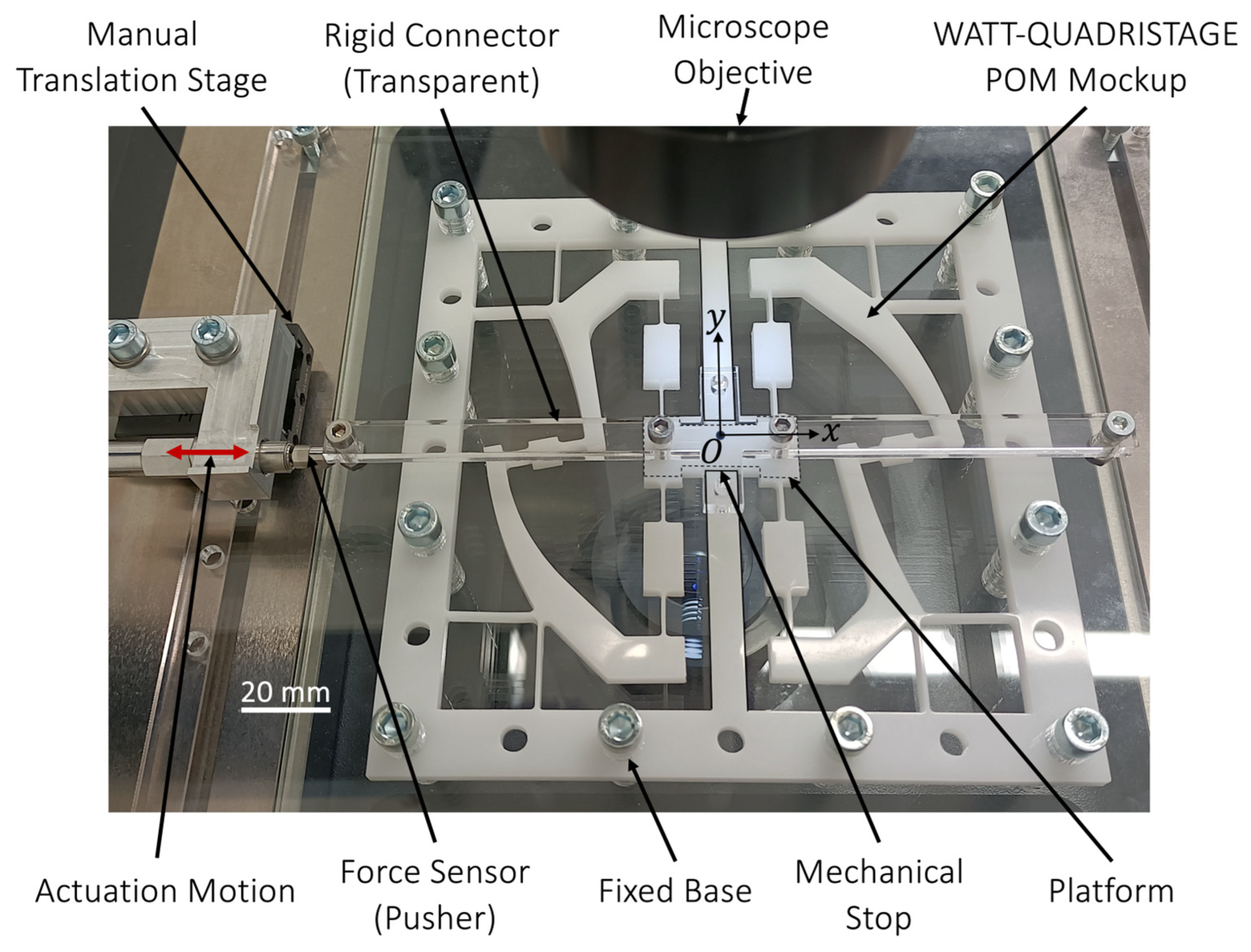
Section 7.4). The mockup of the WATT-QUADRISTAGE was fabricated in POM using a laser cutting machine (manufacturing tolerances of ± 0.1 mm). The dimensions of the demonstrator correspond to the values used in the FEM simulations. A test bench was designed to experimentally evaluate the planar parasitic shifts in the platform and, at the same time, the translational and lateral in-plane stiffnesses.
The setup is composed of a manual translation stage used to push the platform by a specific displacement via a rigid connector. A force sensor (Type 9207, Kistler, Winterthur, Switzerland) measures the mechanism’s elastic restoring force (
Figure 9). The orientation of the mechanism with respect to the setup can be modified in order to measure the restoring force along
or
to evaluate the translational and lateral stiffnesses, respectively. The mockup plane is perpendicular to the direction of gravity to avoid measuring gravity-related forces.
When the mechanism is displaced along the -axis, the parasitic shifts in the platform are assessed via an optical microscope (Opensys 300 MZ, Marcel Aubert, Nidau, Switzerland) located above the setup. Two measuring marks are placed on the mockup platform and on the fixed base (serving as reference), in order to measure its translation displacement , its lateral shift , and its rotation shift .
The translational stiffness and the parasitic shifts are evaluated by incremental displacement of 0.5 mm in both directions along until one of the mechanical stops (located at = ±6 mm) is reached by the platform. Since the parasitic shift may be disturbed by contact with the mechanical stops, the measurements are omitted at = ±6 mm. The support stiffness is measured when the mechanism is translated along by applying a fixed displacement of 0.1 mm. The measurement uncertainty is assumed to be ±0.02 N for the measured forces, ±1 µm for the displacements and , and ±20 µrad for the rotation shift . The measurements are always performed when the system is static. Five repetitions were performed to average the measurements.
7. Results and Discussion
In this section, the FEM performance results of the selected
-RRR rectilinear stage family are compared in terms of translational and support stiffnesses, parasitic translation and rotation shifts, and internal stress. The analytical model is verified by comparing it to the FEM results (
Table 2 and
Table 3). The experimental results of the POM mockup are also presented in this section to physically demonstrate the performance of the new family of rectilinear flexure stages and to validate the models.
7.1. Translational Stiffness
Table 2 shows that the translational stiffness
is nearly equal for the mechanisms having four kinematic chains (i.e., all QUADRISTAGE mechanisms), because their kinematic chains all have identical dimensions. In contrast, the PARA-TRIOSTAGE has a translational stiffness which is 25% lower because it has three kinematic chains instead of four. This rectilinear stage can thus be actuated with less force in comparison to the QUADRISTAGE mechanisms. It can also be noticed that the stiffness constant
is always lower in the FEM models by ~14% with respect to the analytical model. This discrepancy could be attributed to the deformation of the rigid links, including the filets located at the flexure extremities, which are not considered in the analytical model. This assumption was confirmed by an additional FEM simulation of the mechanisms, in which every component that is not a flexure was modeled as a rigid component with infinite stiffness. In that case, the simulated values of
are equal to the ones of the analytical model with less than 0.4% relative variation for all the selected mechanisms.
The stiffness constant predicted by the analytical and FEM models is verified experimentally with the WATT-QUADRISTAGE POM mockup. A stiffness of 0.928 N/mm is obtained by linear regression of its measured force–displacement characteristics. This result is in good agreement with the FEM data, since the relative difference is lower than 1%.
7.2. Support Stiffness
The FEM results show that the mechanism with the maximum values of support stiffnesses along
and around
is the PARA-QUADRISTAGE (
Table 2). This shows that the parallelogram couplers can efficiently transmit forces from one secondary link to another in order to provide higher support stiffness.
The values and of the PARA-TRIOSTAGE are 3.1 and 3.6 times lower in comparison to the PARA-QUADRISTAGE, respectively. This illustrates that, in contrast to a same-orientation coupling (Condition 1), the kinematic chains with a 180-degree relative orientation (Condition 2) can yield larger support stiffnesses.
The WATT-QUADRISTAGE is 1.5 and 20 times less stiff along and around in comparison to the PARA-QUADRISTAGE. It is highly probable that the support stiffness of the WATT-QUADRISTAGE could be increased if the distance and the distance are increased. Indeed, these modifications would imply a reduction in the force transmitted through the coupling links when loads along or around are applied.
The mechanism with the lowest values for
and
is the KEMPE-QUADRISTAGE architecture. This low support stiffness could be explained by the geometry of the relatively large secondary and coupling connections (required to ensure a planar structure) compared with those in the other structures (
Figure 8). The large bodies introduce additional compliance, reducing coupling efficiency and hence support stiffness.
A support stiffness of 196 N/mm is measured on the WATT-QUADRISTAGE prototype. This result is in a large discrepancy with the FEM data, since the measured value is 35% higher than FEM value. This can be explained by the poor manufacturing tolerances of the laser-cut POM mockup which resulted in flexure thickness or length being noticeably greater or lower than anticipated.
Remark 3. Since this paper aims to provide a basic performance comparison of the presented mechanisms, their support stiffness is only evaluated when they are in neutral position (i.e., undeflected). However, it should be understood that the support stiffness of flexure-based mechanisms usually tends to decrease as the mechanism deformation increases, due to geometric stiffness nonlinearities [19,28]. Characterizing the support stiffness of -RRR rectilinear stages in deflected state is one of the future research directions. 7.3. Maximum Stress
The analytical and FEM values of the maximum stress for a range of motion of
±6 mm are reported in
Table 3. In the FEM models, the maximum von Mises stress is situated in the main flexures of the mechanisms (
Figure 8) and is obtained at the maximum amplitude (i.e., at
±6 mm), as expected. Since all mechanisms have identical main flexure dimensions, the analytical model and the FEM model give, respectively, equal and nearly equal maximum stress values (
Table 3). The analytical value is consistently slightly lower than the simulated value. This is primarily due to the stress concentration located near the filets. In addition, the analytical model does not take into account the tension in the main flexures that is produced by the deformation of the secondary and coupling flexures.
Since the simulated maximum stress value never exceeds the yield strength of the material ( 65 MPa), we can predict that the admissible range of motion of the mechanisms is higher than 6 mm. When testing the POM mockup of the WATT-QUADRISTAGE, we observed that the mechanism can indeed be deflected to this stroke and return to its neutral position without noticeable plastic deformation.
7.4. Parasitic Shifts
The parasitic shift in the different mechanisms is shown in
Figure 10 as a function of the displacement
. For the total range of
, the maximum absolute values of the lateral and rotation shifts, i.e.,
and
, are reported in
Table 3. High rectilinear-motion performance is observed across the different mechanisms, although some perform better than others.
In comparison to the other mechanisms having four kinematic chains, the PARA-TRIOSTAGE (with three kinematic chains) shows the lowest rectilinear-motion performance. Indeed, the values of
and
of the latter are approximately one order of magnitude higher than the other mechanisms. The asymmetry of the PARA-TRIOSTAGE (with two kinematic chains on the right side and one on the left side as shown in
Figure 8a) seems to drastically affect the straightness of the stage. This illustrates the advantage of using symmetric configurations based on two pairs of coupled kinematic chains, such as the PARA-QUADRISTAGE, WATT-QUADRISTAGE, and KEMPE-QUADRISTAGE.
The simulations demonstrate lower parasitic shifts for the WATT-QUADRISTAGE in comparison to the PARA-QUADRISTAGE, which is consistent with what is expected from their ideal kinematics (
Section 2). However, the KEMPE-QUADRISTAGE exhibits a higher value for
than the two other 4-RRR rectilinear stages. This FEM result is in contradiction with the ideal kinematics of the KEMPE-QUADRISTAGE having zero parasitic shift. The possible reason for this disparity is that the secondary link rotation is not effectively transmitted throughout the flexure-based Kempe linkage couplers, because the rigid links are not sufficiently stiff. Furthermore, the force transmitted through the coupling links is not aligned with the longitudinal axis of the coupling flexures (due to the modification of Condition 3 for this kind of coupler). These hypotheses are further discussed in
Section 7.5.
The mechanism exhibiting the lowest maximum parasitic shifts
and
, is the WATT-QUADRISTAGE (
Table 3). Advantageously, it is also the mechanism requiring the least amount of space, see
Figure 8. This structure was therefore selected for experimental testing. The measurements of the parasitic shifts carried out on the manufactured WATT-QUADRISTAGE prototype are also plotted in
Figure 10 to be compared with the FEM data. The mean values (points) and the standard deviations (error bars) of the measured lateral platform deviation and rotation are displayed as a function of
. There are noticeable differences in the results between the experiment and the FEM model. Indeed, the measured maximum parasitic translation
is one order of magnitude larger than what the simulations predict (
Table 3). This disparity can be attributed to the manufacturing tolerances of the POM mockup, which may cause flexure deformation that differs significantly from the FEM model. Furthermore, we can observe that the standard deviation is large compared to the mean values, which demonstrates that it is difficult to precisely characterize the parasitic shift in the POM prototype with the proposed test bench. In addition, the FEM model does not consider gravity effects which may affect the actual trajectory of the stage. Nevertheless, this experiment demonstrates some preliminary results of the performance of these rectilinear stages, as it reveals maximum parasitic shifts of 2.82 µm laterally and 50.4 µrad in rotation over a 11 mm translation stroke. Further experimental validation is foreseen by measuring the straightness error of titanium alloy prototypes fabricated by Electrical Discharge Machining (EDM) using high-resolution laser displacement sensors.
7.5. Performance Ranking and Further Optimizations
In summary, the FEM results show that the WATT-QUADRISTAGE performs significantly better than the other selected mechanisms in terms of rectilinearity and space occupation. It exhibits a maximum parasitic translation of = 0.258 µm and a maximum parasitic rotation of = 50.4 µrad for a range of motion of = 12 mm. This leads to a normalized straightness error of = 2.15 × 10⁻⁵. The mechanism with the highest support stiffness is the PARA-QUADRISTAGE, with a lateral stiffness of = 195 N/mm and rotation stiffness = 588 Nm/rad. It leads to an elevated lateral to translational stiffness ratio of = 213. The presented structures have approximately equivalent maximum stresses and thus equivalent admissible strokes.
Using other manufacturing technologies, the
-RRR rectilinear mechanisms could be further optimized by decreasing the thickness ratio between the flexures and the frame parts. This would make the frame parts stiffer relative to the flexures, in such a way that the frame parts deform considerably less and approximate rigid links better. The deflection of the flexure-based stages would then correspond more to their ideal joint kinematics. This could improve rectilinearity as well as increase the support stiffness over translational stiffness ratio. To verify this hypothesis, we simulated the mechanisms in
Figure 8, considering that the frame parts are infinitely stiff and thus do not deform. We observed that the support stiffness and the parasitic shift was, respectively, increased and decreased by approximately one order of magnitude for every mechanism. As such, the performance ranking of the mechanisms remains the same as discussed above. It is surprising that the PARA-QUADRISTAGE and the WATT-QUADRISTAGE, which have theoretically higher parasitic shifts than KEMPE-QUADRISTAGE, still perform better than the latter. For the KEMPE-QUADRISTAGE to improve performance, it is therefore necessary to optimize the location and orientation of flexures. In subsequent studies, it would be worth implementing parametric or topology optimization in order to minimize the parasitic shift and maximize the support stiffness of this mechanism.
8. Application Example: Stiffness-Reduced Silicon Rectilinear Stage
Since the presented
-RRR rectilinear mechanisms can have higher translation stiffness (due to the larger number of kinematic chains) compared to existing flexure linear stages, we investigate a method to reduce the translational stiffness of such mechanisms while maintaining a high support stiffness [
29]. In this section, we test the ability of tuning the translational stiffness of a WATT-QUADRISTAGE rectilinear stage by incorporating buckling beams. To provide applicability at MEMS scale, the mechanism is fabricated in silicon using DRIE (Deep Reactive Ion Etching) and the preloading of the buckling beams is performed by thermal oxidation. Furthermore, Preloading Chevron Mechanisms (PCMs) [
30,
31] are employed to increase the operating stroke of the stage by enhancing the residual stress effects.
8.1. Stiffness Reduction Concept
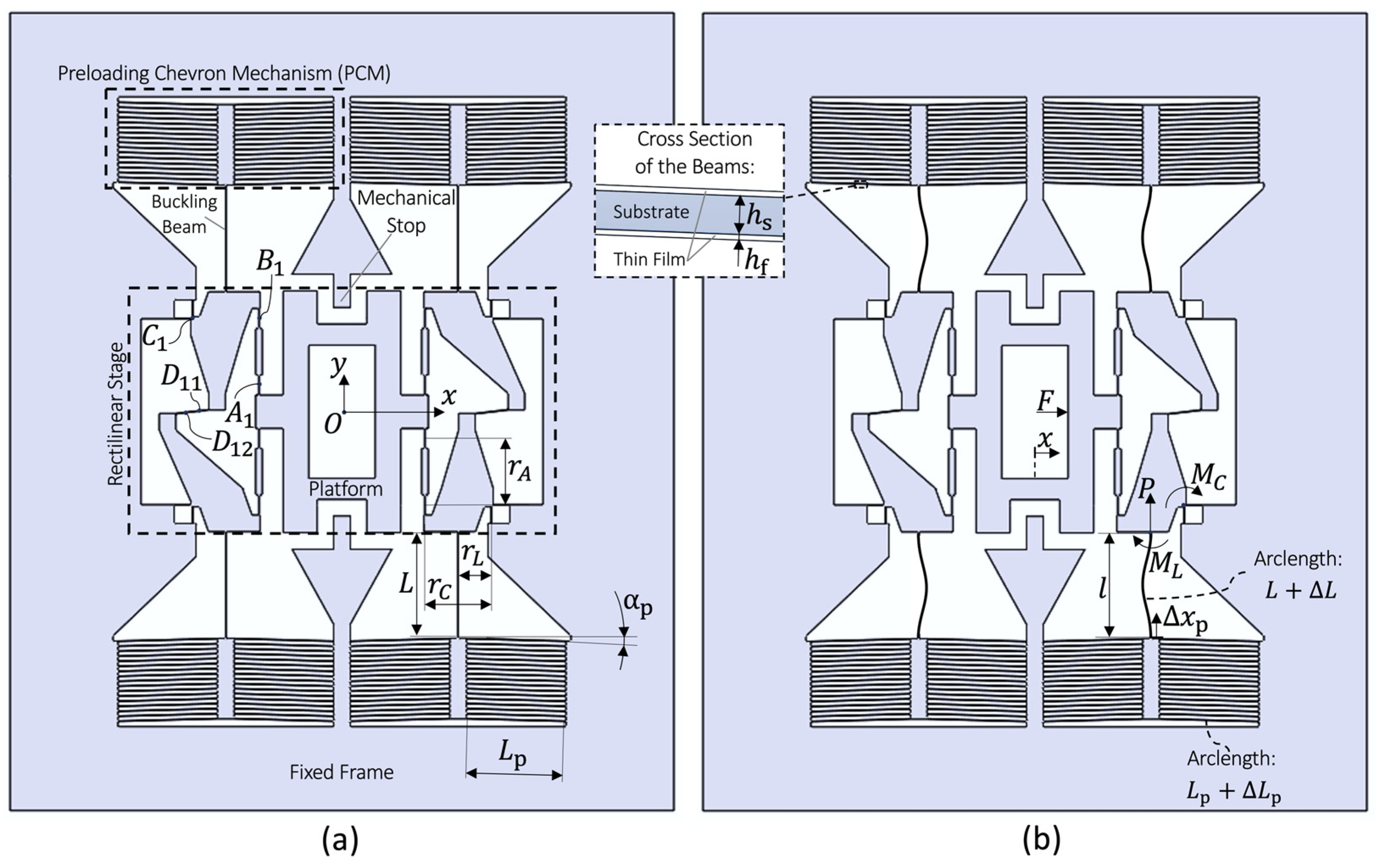
Figure 11 presents the silicon WATT-QUADRISTAGE mechanism preloaded by
PCM-preloaded buckling beams. These buckling beams apply a nearly constant moment
to the secondary links. The potential energy
denotes the energy associated with the preloading introduced by the buckling beams in the flexure mechanism. Since the secondary links, to which the buckled beams are attached, always rotate in the same direction (because
, the energy stored in the buckled beams consistently decreases as the moving stage undergoes rectilinear displacement. This energy reduction with respect to the stage motion can be modeled as an effective negative stiffness, denoted as
, which reduces the positive stiffness
of the stage. The potential energy
can be computed as the work of the moment
applied by the
buckled beams as follows:
where from Equations (4) and (5), the expression for the effective negative stiffness can be derived as:
In the vicinity of the neutral position, the buckled beams have fixed–fixed boundary conditions, leading to the following axial load and reaction moment [
32]:
where
is the total flexural rigidity of the beams, accounting for the flexural rigidities of both the substrate and the thin film (see inset in
Figure 11), and
. It can interestingly be noted that if the buckled beams deflect with an outward buckling direction (as opposed to the inward buckling direction illustrated in
Figure 11b), then the sign of
is reversed. Considering both the positive stiffness of the stage flexures
(Equation (6)) and the negative stiffness provided by the buckling beams (Equation (10)), the total stiffness
is given by:
Note that the total stiffness can either be positive (stiffness adjustment), near-zero (zero-force properties), or negative (bistable behaviors).
8.2. FEM and Experimental Validations
The mechanism is designed, manufactured, and tested experimentally. The FEM and experimental methods are as described in [
30]. The flexures of the rectilinear stage as well as the buckling beams all have the same cross-section. Their silicon core has a thickness
= 20 µm and an out-of-plane depth
= 380 µm. The thickness of the thermal oxide layer deposited all around the silicon core is equal to
= 3 µm. The PCMs each have 50 preloading beams. The beam lengths and other parameter values are provided in
Table 4. The same method as in [
30] is used to extract the residual stress value in the oxide. A residual stress of −290 MPa (compressive) is measured in the fabricated wafer.
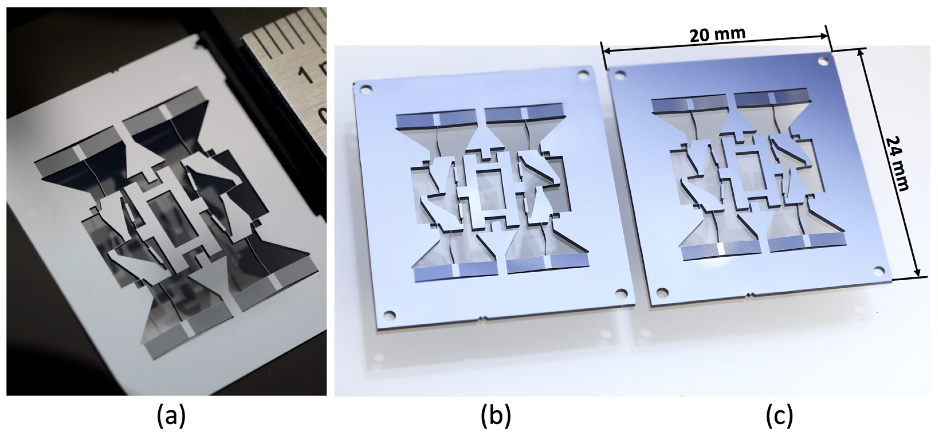
Photographs of the manufactured prototypes are shown in
Figure 12. We can see that the buckling beams of the mechanisms can indeed either buckle inwards or outwards. An equivalent prototype without buckling beams is also tested to assess the stiffness reduction. The measured force–displacement characteristics of the different mechanisms are presented in
Figure 13, along with analytical and FEM data.
The stiffness reduction method is validated since the stiffness is greatly reduced (even to a negative value) when incorporating buckling beams in the WATT-QUADRISTAGE structure. Indeed, the measurements, which are in good agreement with the models, show that the translational stiffness is reduced by 98% (monostable prototype) and 112% (bistable prototype) when buckling beams are incorporated with outward and inward buckling directions, respectively. Stiffness reduction can be very interesting for low-voltage actuators or highly sensitive MEMS devices [
33,
34,
35], whereas bistable properties could be advantageous for MEMS optical switches or energy harvesters [
36,
37].
Technically, the buckling direction is switched by manually pushing the buckling beams with a small needle. In practical systems, MEMS actuators (e.g., comb-drive or thermal actuators) might be integrated to modify the buckling direction of the different buckled beams in situ, if triggering and resetting the mechanism bistability is required. Note that the monostable state of the mechanism is limited to a displacement of ±0.35 mm around the neutral position. Indeed, when this stroke is exceeded, all the buckled beams snap to the inward buckling configuration, making the mechanism bistable. In that case, the mechanism cannot be returned to its monostable configuration without actively changing the buckling direction. Mechanical stops could be employed to limit the translation stroke to mitigate snap-through of the mechanism from monostable to bistable.
Remark 4. It can be seen that the FEM and experimental force–displacement curves exhibit a small nonlinear load-stiffening effect with displacement, whereas the analytical model has a linear curve with constant stiffness (Figure 13). This nonlinearity is considered acceptable, because it is small compared to overconstrained flexure stages with similar dimensions, where the stiffness increases significantly with displacement, strongly reducing the motion range [11].
For both monostable and bistable configurations of the mechanism, FEM simulations show parasitic shifts less than 0.66 nm along
and 6.7 µrad around
for a total stroke of ±0.5 mm. Due to the small scale of these mechanisms, we did not perform any experiment to validate these parasitic shift values. The lateral stiffness of the platform is
= 1086 N/mm, regardless of whether the mechanism is preloaded by buckling beams (inward or outward orientations) or not. This leads to ratios between support and translational stiffness
of 6.0 × 10
3 and 2.6 × 10
5 when the mechanism is, respectively, non-preloaded and preloaded by outward buckling beams. With these values, we can notice the importance of employing stiffness reduction along the primary axis in order to increase the ratio between support and translational stiffness [
19].
9. Conclusions
In this paper, we present a novel family of -RRR planar mechanisms where the kinematic chains are coupled to reduce the mobility of the platform to a 1-DOF rectilinear translation. The following three types of couplers are investigated: parallelogram, Watt, and Kempe linkages, which lead to different orders of parasitic shifts. Based on the ideal-joint kinematics, we select four design variants (named PARA-TRIOSTAGE, PARA-QUADRISTAGE, WATT-QUADRISTAGE, and KEMPE-QUADRISTAGE) and propose flexure-based implementations. We discuss the performance of these novel compliant rectilinear stages having the same geometric constraints and material (POM). The comparison, based on FEM models, covers the parasitic shifts, the maximum internal stress, and the support stiffness. In summary, the WATT-QUADRISTAGE shows the minimum parasitic shift and the lowest space consumption when compared to the other structures. Indeed, its platform exhibits a theoretical straightness inaccuracy of 0.258 µm and a maximum parasitic rotation of 12.6 µrad for a total stroke of 12 mm. An experimental study performed on a POM mockup validated the low parasitic shifts and high support stiffness properties of such rectilinear-motion mechanisms. With such performance, these scalable and easy-to-manufacture rectilinear mechanisms can be used for a large spectrum of applications.
We also demonstrate that the translational stiffness of such rectilinear mechanisms can be greatly reduced by integrating post-buckled beams into the structure. Indeed, fully compliant silicon prototypes of the WATT-QUADRISTAGE were built, thermally oxidized to provide buckling, and tested experimentally. The measurements show that the translational stiffness was reduced by 98% when incorporating buckled beams, while the support stiffness remains the same. The same mechanism becomes bistable if the buckling beams are buckled in the opposite direction (stiffness reduction of 112%).
Further research will include topology optimization to further minimize the parasitic shift and maximize the support stiffness of this new family of kinematics-based flexure rectilinear mechanisms. We will validate the geometric optimization with experiments made on titanium alloy prototypes fabricated by wire-cut EDM.
Author Contributions
Conceptualization, all authors; methodology, L.T.-D., C.V., F.C. and S.H.; software, L.T.-D.; validation, L.T.-D. and C.V.; formal analysis, L.T.-D. and C.V.; investigation, L.T.-D.; resources, S.H.; data curation, S.H.; writing—original draft preparation, L.T.-D.; writing—review and editing, all authors; visualization, L.T.-D., C.V. and S.H.; supervision, S.H.; project administration, S.H.; funding acquisition, S.H. All authors have read and agreed to the published version of the manuscript.
Funding
This research received no external funding.
Data Availability Statement
Data are contained within the article.
Acknowledgments
The authors thank Michel Despont and Yves Pétremand from CSEM for the manufacturing of the silicon parts and the discussions related to the design. We also thank Quentin Gubler for his help in carrying out the design, the FEM modeling, and the experiment of the POM mockups.
Conflicts of Interest
The authors declare no conflicts of interest.
References
- Xu, Q. Design and Development of a Compact Flexure-Based XY Precision Positioning System With Centimeter Range. IEEE Trans. Ind. Electron. 2014, 61, 893–903. [Google Scholar] [CrossRef]
- Zhang, H.; Wu, Z.; Xu, Q. Design of a New XY Flexure Micropositioning Stage With a Large Hollow Platform. Actuators 2020, 9, 65. [Google Scholar] [CrossRef]
- Choi, Y.; Sreenivasan, S.V.; Choi, B.J. Kinematic design of large displacement precision XY positioning stage by using cross strip flexure joints and over-constrained mechanism. Mech. Mach. Theory 2008, 43, 724–737. [Google Scholar] [CrossRef]
- Zhang, Z.; Yan, P.; Hao, G. A Large Range Flexure-Based Servo System Supporting Precision Additive Manufacturing. Engineering 2017, 3, 708–715. [Google Scholar] [CrossRef]
- Algamili, A.S.; Khir, M.H.M.; Dennis, J.O.; Ahmed, A.Y.; Alabsi, S.S.; Hashwan, S.S.B.; Junaid, M.M. A Review of Actuation and Sensing Mechanisms in MEMS-Based Sensor Devices. Nanoscale Res. Lett. 2021, 16, 16. [Google Scholar] [CrossRef]
- Hao, G.; Zhu, J. Design of a Monolithic Double-Slider Based Compliant Gripper with Large Displacement and Anti-Buckling Ability. Micromachines 2019, 10, 665. [Google Scholar] [CrossRef]
- Beroz, J.; Awtar, S.; Bedewy, M.; Tawfick, S.; Hart, A.J. Compliant microgripper with parallel straight-line jaw trajectory for nanostructure manipulation. In Proceedings of the ASPE 2011 Annual Meeting, Denver, CO, USA, 13–18 November 2011. [Google Scholar]
- Cosandier, F.; Eichenberger, A.; Baumann, H.; Jeckelmann, B.; Bonny, M.; Chatagny, V.; Clavel, R. Development and integration of high straightness flexure guiding mechanisms dedicated to the METAS watt balance Mark II. Metrologia 2014, 51, S88–S95. [Google Scholar] [CrossRef]
- Darnieder, M.; Pabst, M.; Wenig, R.; Zentner, L.; Theska, R.; Fröhlich, T. Static behavior of weighing cells. J. Sens. Sens. Syst. 2018, 7, 587–600. [Google Scholar] [CrossRef]
- Rubbert, L.; Bitterli, R.; Ferrier, N.; Fifanski, S.; Vardi, I.; Henein, S. Isotropic springs based on parallel flexure stages. Precis. Eng. 2016, 43, 132–145. [Google Scholar] [CrossRef]
- Cosandier, F.; Henein, S.; Richard, M.; Rubbert, L. The Art of Flexure Mechanism Design; EPFL Press: Lausanne, Switzerland, 2017. [Google Scholar]
- Gräser, P.; Linß, S.; Harfensteller, F.; Torres, M.; Zentner, L.; Theska, R. High-precision and large-stroke XY micropositioning stage based on serially arranged compliant mechanisms with flexure hinges. Precis. Eng. 2021, 72, 469–479. [Google Scholar] [CrossRef]
- Hricko, J. Design of Compliant Micro-Stage Based on Peaucellier–Lipkin Straight-Line Mechanism. In Proceedings of the RAAD 2014 23rd International Conference on Robotics in Alpe-Adria-Danube Region, Smolenice Castle, Slovakia, 3–5 September 2014. [Google Scholar]
- Tissot-Daguette, L.; Schneegans, H.; Gubler, Q.; Baur, C.; Henein, H. Rectilinear translation four-bar flexure mechanism based on four Remote Center Compliance pivots. In Proceedings of the Conference of the European Society for Precision Engineering and Nanotechnology, Geneva, Switzerland, 30 May–3 June 2022. [Google Scholar]
- Zhao, H.; Bi, S.; Yu, J. A novel compliant linear-motion mechanism based on parasitic motion compensation. Mech. Mach. Theory 2012, 50, 15–28. [Google Scholar] [CrossRef]
- Hubbard, N.B.; Wittwer, J.W.; Kennedy, J.A.; Wilcox, D.L.; Howell, L.L. A novel fully compliant planar linear-motion mechanism. In Proceedings of the ASME 2004 International Design Engineering Technical Conferences and Computers and Information in Engineering Conference, Salt Lake City, UT, USA, 28 September–2 October 2004. [Google Scholar]
- Liu, Z.; Zhang, Z.; Yan, P. A self-adjusting stiffness center design for large stroke compliant XY nanomanipulators. Mech. Sci. 2018, 9, 41–50. [Google Scholar] [CrossRef]
- Li, Y.; Xu, Q. Design and Robust Repetitive Control of a New Parallel-Kinematic XY Piezostage for Micro/Nanomanipulation. IEEE/ASME Trans. Mechatron. 2012, 17, 1120–1132. [Google Scholar] [CrossRef]
- Brouwer, D.M.; Meijaard, J.P.; Jonker, J.B. Large deflection stiffness analysis of parallel prismatic leaf-spring flexures. Precis. Eng. 2013, 37, 505–521. [Google Scholar] [CrossRef]
- Vallat, C.; Tissot-Daguette, L.; Cosandier, F.; Henein, S. Rectilinear Flexure-based Translation Stage Family with Minimized Parasitic Shift, High Support Stiffness and Large Range of Motion. 2025. Available online: https://engrxiv.org/preprint/view/4458/version/6077 (accessed on 10 June 2025).
- Tissot-Daguette, L.; Vallat, C.; Cosandier, F.; Henein, S. One Degree of Freedom Linear Stages with Minimised Parasitic Shift. Patent EP24218366.3, 9 December 2024. [Google Scholar]
- Hao, G.; Li, H.; He, X.; Kong, X. Conceptual design of compliant translational joints for high-precision applications. Front. Mech. Eng. 2014, 9, 331–343. [Google Scholar] [CrossRef]
- Xu, Q. Design and Development of a Flexure-Based Dual-Stage Nanopositioning System with Minimum Interference Behavior. IEEE Trans. Autom. Sci. Eng. 2012, 9, 554–563. [Google Scholar] [CrossRef]
- Tissot-Daguette, L.; Cosandier, F.; Thalmann, E.; Henein, S. Near-Zero Parasitic Shift Flexure Pivots Based on Coupled n-RRR Planar Parallel Mechanisms. ASME J. Mech. Robot. 2024, 16, 111006. [Google Scholar] [CrossRef]
- Kempe, A.B. On a General Method of describing Plane Curves of the nth degree by Linkwork. Proc. Lond. Math. Soc. 1875, 1, 213–216. [Google Scholar] [CrossRef]
- Howell, L.L. Compliant Mechanisms; Wiley: New York, NY, USA, 2001. [Google Scholar]
- Pei, X.; Yu, J.; Zong, G.; Bi, S. An effective pseudo-rigid-body method for beam-based compliant mechanisms. Precis. Eng. 2010, 34, 634–639. [Google Scholar] [CrossRef]
- Nijenhuis, M.; Meijaard, J.P.; Mariappan, D.; Herder, J.L.; Brouwer, D.M.; Awtar, S. An Analytical Formulation for the Lateral Support Stiffness of a Spatial Flexure Strip. ASME J. Mech. Des. 2017, 139, 051401. [Google Scholar] [CrossRef]
- de Jong, J.; Theans, S.; Epping, L.; Brouwer, D.M. Improving Support Stiffness of Flexure Mechanisms by Statically Balancing. In Proceedings of the 36th Annual Meeting of the American Society for Precision Engineering, Minneapolis, MN, USA, 1–5 November 2021. [Google Scholar]
- Tissot-Daguette, L.; Cosandier, F.; Gubler, Q.; Petremand, Y.; Despont, M.; Henein, S. Residual Stress Chevron Preloading Amplifier for Large-Stroke Stiffness Reduction of Silicon Flexure Mechanisms. J. Micromech. Microeng. 2025, 35, 025003. [Google Scholar] [CrossRef]
- Tissot-Daguette, L.; Henein, S. Flexure Based Mechanism with Reduced Stiffness. Patent EP24199124.9, 9 September 2024. [Google Scholar]
- Tissot-Daguette, L.; Schneegans, H.; Thalmann, E.; Henein, S. Analytical modeling and experimental validation of rotationally actuated pinned–pinned and fixed–pinned buckled beam bistable mechanisms. Mech. Mach. Theory 2022, 174, 104874. [Google Scholar] [CrossRef]
- de Laat, M.L.C.; Pérez Garza, H.H.; Herder, J.L.; Ghatkesar, M.K. A review on in situ stiffness adjustment methods in MEMS. Micromech. Microeng. 2016, 26, 063001. [Google Scholar] [CrossRef]
- Hussein, H.; Wang, C.; Esteves, R.A.; Kraft, M.; Fariborzi, H. Near-zero stiffness accelerometer with buckling of tunable electrothermal microbeams. Microsyst. Nanoeng. 2024, 10, 43. [Google Scholar] [CrossRef] [PubMed]
- Xiong, R.; Xu, X.; Liu, Y.; Du, S.; Jin, L.; Chen, F.; Wu, T. A miniaturized MEMS accelerometer with anti-spring mechanism for enhancing sensitivity. Microsyst. Nanoeng. 2025, 11, 42. [Google Scholar] [CrossRef]
- Xu, R.; Akay, H.; Kim, S.G. Buckled MEMS Beams for Energy Harvesting from Low Frequency Vibrations. Research 2019, 2019, 2581241. [Google Scholar] [CrossRef]
- Yang, Y.J.; Liao, B.T.; Kuo, W.C. A novel 2 × 2 MEMS optical switch using the split cross-bar design. J. Micromech. Microeng. 2007, 17, 875. [Google Scholar] [CrossRef]
Figure 1.
Type I TRIOSTAGE. (a) 3-RRR sub-mechanism (3-DOF). (b) Coupling sub-mechanism (1-DOF). (c) Type I TRIOSTAGE satisfying exclusively Conditions 1 to 3 in an arbitrary position. (d) Mechanism (c) in neutral position. (e) Type I TRIOSTAGE satisfying all Conditions 1 to 6 in neutral position (named PARA-TRIOSTAGE). (f) Mechanism (e) translated along the -axis.
Figure 2.
Hybrid TRIOSTAGES. Type I + II TRIOSTAGE: TRIOSTAGE based on parallelogram and Watt’s linkage couplers in (a) neutral and (b) deformed position. Type I + III TRIOSTAGE: TRIOSTAGE based on parallelogram and Kempe’s linkage couplers in (c) neutral and (d) deformed position.
Figure 2.
Hybrid TRIOSTAGES. Type I + II TRIOSTAGE: TRIOSTAGE based on parallelogram and Watt’s linkage couplers in (a) neutral and (b) deformed position. Type I + III TRIOSTAGE: TRIOSTAGE based on parallelogram and Kempe’s linkage couplers in (c) neutral and (d) deformed position.
Figure 3.
PARA-QUADRISTAGE: 4-RRR rectilinear stage with two parallelogram linkage couplers (a) in neutral and (b) in deformed position.
Figure 3.
PARA-QUADRISTAGE: 4-RRR rectilinear stage with two parallelogram linkage couplers (a) in neutral and (b) in deformed position.
Figure 4.
WATT-QUADRISTAGE: 4-RRR rectilinear stage with two Watt’s linkage couplers (a) in neutral and (b) in deformed position.
Figure 4.
WATT-QUADRISTAGE: 4-RRR rectilinear stage with two Watt’s linkage couplers (a) in neutral and (b) in deformed position.
Figure 5.
KEMPE-QUADRISTAGE: 4-RRR rectilinear stage with two Kempe’s linkage couplers (a) in neutral and (b) in deformed position.
Figure 5.
KEMPE-QUADRISTAGE: 4-RRR rectilinear stage with two Kempe’s linkage couplers (a) in neutral and (b) in deformed position.
Figure 6.
Flexure implementation of (a) the PARA-TRIOSTAGE, (b) the PARA-QUADRISTAGE, (c) the WATT-QUADRISTAGE, and (d) the KEMPE-QUADRISTAGE. The flexure rectilinear stages are all presented at equilibrium position (i.e., undeformed).
Figure 6.
Flexure implementation of (a) the PARA-TRIOSTAGE, (b) the PARA-QUADRISTAGE, (c) the WATT-QUADRISTAGE, and (d) the KEMPE-QUADRISTAGE. The flexure rectilinear stages are all presented at equilibrium position (i.e., undeformed).
Figure 7.
Pseudo-rigid-body model of one of the kinematic chains of the flexure-based -RRR rectilinear mechanisms in (a) neutral position and (b) translated by a displacement .
Figure 7.
Pseudo-rigid-body model of one of the kinematic chains of the flexure-based -RRR rectilinear mechanisms in (a) neutral position and (b) translated by a displacement .
Figure 8.
FEM simulations of (a) the PARA-TRIOSTAGE, (b) the PARA-QUADRISTAGE, (c) the WATT-QUADRISTAGE, and (d) the KEMPE-QUADRISTAGE, all translated by a displacement of mm.
Figure 8.
FEM simulations of (a) the PARA-TRIOSTAGE, (b) the PARA-QUADRISTAGE, (c) the WATT-QUADRISTAGE, and (d) the KEMPE-QUADRISTAGE, all translated by a displacement of mm.
Figure 9.
Experimental setup to characterize the parasitic shifts and the stiffness of the WATT-QUADRISTAGE POM mockup.
Figure 9.
Experimental setup to characterize the parasitic shifts and the stiffness of the WATT-QUADRISTAGE POM mockup.
Figure 10.
FEM and experimental results of the selected rectilinear stages: (a) lateral and (b) rotational parasitic shifts as a function of the translational displacement .
Figure 10.
FEM and experimental results of the selected rectilinear stages: (a) lateral and (b) rotational parasitic shifts as a function of the translational displacement .
Figure 11.
WATT-QUADRISTAGE rectilinear stage shown in neutral position (a) before and (b) after thermal oxidation.
Figure 11.
WATT-QUADRISTAGE rectilinear stage shown in neutral position (a) before and (b) after thermal oxidation.
Figure 12.
Photographs of preloaded silicon WATT-QUADRISTAGE. (a) Close-up view of one of the prototypes. The scale on the upper-right corner displays millimetric graduations. (b) If the buckling beams are buckled outwards, the mechanism is monostable. (c) If they are buckled inwards, the mechanism is bistable.
Figure 13.
Force–displacement characteristics of the WATT-QUADRISTAGE silicon mechanisms.
Figure 13.
Force–displacement characteristics of the WATT-QUADRISTAGE silicon mechanisms.
Table 1.
Design parameters of the selected flexure rectilinear stages (see
Figure 6).
Table 1.
Design parameters of the selected flexure rectilinear stages (see
Figure 6).
| | Parameter | Value (mm) |
|---|
| Main Flexures | | 10 |
| 30 |
| Secondary Flexures | | 2.5 |
| 20 |
| 30 |
| Coupling Flexures | | 5 |
Table 2.
Translational and support stiffnesses of the selected flexure rectilinear stages, obtained from the analytical model (AM), the simulations (FEM), and the experiment (EXP).
Table 2.
Translational and support stiffnesses of the selected flexure rectilinear stages, obtained from the analytical model (AM), the simulations (FEM), and the experiment (EXP).
| | Translational Stiffness | Support Stiffness |
|---|
| |
(N/mm) |
(N/mm) | (Nm/rad) |
|---|
| | AM | FEM | EXP | FEM | EXP | FEM |
|---|
| PARA-TRIOSTAGE | 0.804 | 0.692 | - | 62.2 | - | 164 |
| PARA-QUADRISTAGE | 1.07 | 0.917 | - | 195 | - | 588 |
| WATT-QUADRISTAGE | 1.07 | 0.922 | 0.928 | 127 | 196 | 29.5 |
| KEMPE-QUADRISTAGE | 1.07 | 0.921 | - | 49.7 | - | 12.0 |
Table 3.
Maximum stress and maximum parasitic shift magnitude of the selected flexure rectilinear stages, obtained from the analytical model (AM), the simulations (FEM), and the experiment (EXP).
Table 3.
Maximum stress and maximum parasitic shift magnitude of the selected flexure rectilinear stages, obtained from the analytical model (AM), the simulations (FEM), and the experiment (EXP).
| | Maximum Stress | Maximum Parasitic Shift |
|---|
| |
(MPa) |
(µm) |
(µrad) |
|---|
| | AM | FEM | FEM | EXP | FEM | EXP |
|---|
| PARA-TRIOSTAGE | 38.6 | 41.7 | 36.5 | - | 742 | - |
| PARA-QUADRISTAGE | 38.6 | 41.7 | 2.04 | - | 221 | - |
| WATT-QUADRISTAGE | 38.6 | 43.3 | 0.258 | 2.82 | 12.6 | 50.4 |
| KEMPE-QUADRISTAGE | 38.6 | 42.6 | 8.78 | - | 74.8 | - |
Table 4.
Design parameters of the silicon WATT-QUADRISTAGE mechanism (see
Figure 11).
Table 4.
Design parameters of the silicon WATT-QUADRISTAGE mechanism (see
Figure 11).
| | Parameter | Value |
|---|
| Main Flexures | | 0.6 mm |
| 2 mm |
| Secondary Flexures | | 50 µm |
| 0.5 mm |
| 2 mm |
| Coupling Flexures | | 0.5 mm |
| Buckling Beams | | 3.2 mm |
| 1 mm |
| Preloading Chevron Mechanism | | 3 mm |
| 1.5 deg |
| Disclaimer/Publisher’s Note: The statements, opinions and data contained in all publications are solely those of the individual author(s) and contributor(s) and not of MDPI and/or the editor(s). MDPI and/or the editor(s) disclaim responsibility for any injury to people or property resulting from any ideas, methods, instructions or products referred to in the content. |
© 2025 by the authors. Licensee MDPI, Basel, Switzerland. This article is an open access article distributed under the terms and conditions of the Creative Commons Attribution (CC BY) license (https://creativecommons.org/licenses/by/4.0/).


 ,
, 


