1. Introduction
Robotics plays a pivotal role in contemporary space missions. The development of specialized robots has enabled humans to explore and operate in previously inaccessible environments. Of these applications, one of the most significant is the field of manipulators. These are robotic arms that are employed primarily for space activity, docking [
1], close-proximity operations [
2], assembly, and maintenance in both orbital and planetary surface environments, allowing for the performance of tasks that are infeasible or excessively risky for humans. [
3]
Among the various types of manipulators employed in the context of different space missions, it is necessary to highlight the first robotic arm deployed in space: the Remote Manipulator System (RMS) designed specifically for the Space Shuttle, also known as Canadarm-1. This system made its inaugural flight aboard the Space Shuttle Columbia (STS-2) in November 1981. The RMS was primarily designed for the capture and manoeuvring of cargo in free flight. However, it has been employed in a wide variety of other applications as well, including the assembly of the International Space Station, support for extra-vehicular activities, and orbital inspections. Its versatility has made it an experimental platform for materials studies and enabled the performance of unique tasks, including ice removal during shuttle re-entry missions [
4]. It is also worth mentioning the manipulators developed for the assembly, maintenance, and scientific research activities of the International Space Station (ISS). These include the Mobile Servicing System (MSS), which comprises the Space Station Remote Manipulator System (SSRMS), Special Purpose Dextrous Manipulator (SPDM), and Mobile Base System (MBS); the Japanese Experiment Module Remote Manipulator System (JEMRMS); and the European Robotic Arm (ERA) [
5].
The use of robotic arms in satellites has a more recent history. In particular, the first example of a satellite equipped with a manipulator was the Engineering Test Satellite (ETS-VII), which was launched on 27 November 1997 to conduct automated rendezvous docking and space robot technology experiments [
6]. Other pertinent missions involving large satellites equipped with robotic manipulators include the Orbital Express mission developed by the Defense Advanced Research Projects Agency (DARPA) [
7]. In this mission, the first autonomous transfer of an additional battery and backup computer to a target spacecraft was successfully executed. Another notable mission is the Spacecraft for the Universal Modification of Orbits (SUMO), which aims to combine stereo-photogrammetry with robotic manipulators in order to facilitate the retrieval of objects from a spacecraft [
8].
Although manipulators are a common feature of large satellites, their extension to microsatellites has been slower. For example, we can take a case application on CubeSat-type satellites. These are small satellites based on standard units (commonly referred to as ’U’) with dimensions of 10 × 10 × 10 cm [
9,
10]. The applications of CubeSats extend to a range of disciplines, including earth monitoring, astrophysics, remote sensing, technology demonstration, and space science [
11]. The development of manipulators for these types of satellites currently remains in the planning stage due to the limited space in which this complex technology must be implemented.
Among the most relevant applications are those proposed by Silva et al. [
12], who suggested a robotic arm solution integrated into the payload of a CubeSat 2U. This 3-DoF (Degrees of Freedom) manipulator was designed with the objective of assisting or replacing astronauts during Extra-Vehicular Activities (EVA) on the International Space Station. Liu et al. [
13] proposed an innovative concept for a deployable robotic arm, designated Cubot. The manipulator is designed for on-orbit servicing, with a particular focus on removal of space debris and maintenance of the space station. The robotic arm, which folds into a space of 1U, comprises three active and three passive joints that lock when the arm is deployed, reducing the effective degrees of freedom from six to three. Örger et al. [
14] presented a concept for a CubeSat equipped with two robotic arms, each with 5 degrees of freedom. Their design is intended for on-orbit servicing, with a particular focus on inspection and control of spacecraft through cameras mounted on the arms. In [
15], McCormick et al. presented the REMORA project, which aims to implement a robotic arm that can be adapted to CubeSats with 6/12 U configurations. Their article presents an interesting case study of a satellite equipped with a 5-DoF robotic arm that can be folded into a 2U configuration. The objective of the satellite is to mitigate the risk of collisions with large debris in Low-Earth Orbit (LEO). The article describes the mission design phases, starting with the launch of the satellite and ending with the docking of the debris object. It also presents the robotic payload and the design of the arm in order to illustrate the choice of end-effector type. In [
16], McCormick et al. illustrate the feasibility study of a small satellite platform with Cluster-Forming On-Board Robotic Manipulators (CFORM), i.e., a robotic arm designed for docking. This study is of particular interest due to the high packing capacity of the system, which can fit into a 0.5 U CubeSat. Zeis et al. [
17] presented a very interesting modular robotic arm for small satellites called the Little Inspection and Servicing Arm (LISA). This prototype is equipped with 24 degrees of freedom and takes up only 1U when folded. The most significant scientific outcome in the field of CubeSats with manipulators is represented by the RSat project [
18]. This work is of particular interest; it differs from those previously discussed in that it was successfully launched into orbit in 2018 as part of NASA’s Educational Launch of Nanosatellites (ELaNa) Mission 19. The RSat is a 3U CubeSat equipped with two robotic manipulators for on-orbit servicing. The RSat project is part of the larger Intelligent Space Assembly Robot (ISAR) project, which aims to advance in-orbit assembly technology to the point where a constellation of satellites can perform semi-autonomous or autonomous assembly operations in space [
19].
The current technological landscape demonstrates growing interest in the development of miniaturised robotic systems for CubeSats, as evidenced by the numerous design solutions presented in the scientific literature. Though mostly still in the on-orbit testing phase, these prototypes demonstrate the ability to perform a range of operations, including component maintenance and repair, sample collection, and establishing links between multiple satellites. Their applications are primarily focused on tasks such as in-orbit servicing, assembly, or inspection.
To date, however, no dedicated applications have been developed leveraging a robotic arm to control the attitude of CubeSat satellites, a function that is typically managed by standard attitude control systems [
20,
21,
22]. Specifically, the innovative concept of utilizing a robotic manipulator as an integrated passive component for spacecraft attitude stabilization remains largely unexplored in the scientific literature.
Our study addresses this research gap by investigating the feasibility of employing a robotic manipulator for passive attitude stabilization, specifically, a C-arm designed for a 1U CubeSat. We propose a novel approach in which the C-arm is initially utilized as a gravity gradient boom and subsequently enhanced with a permanent magnet at its extremity to function as a passive magnetic control device. The primary objective is to ascertain the viability and performance of the C-arm in these unconventional roles, particularly for nanosatellite missions where mission constraints often favour simplicity and power efficiency. To achieve this, a simplified multibody model of the entire CubeSat system, including the C-arm, is developed and analysed using numerical simulations to quantify key attitude parameters such as oscillation amplitudes (e.g., maximum angular deviations) and frequencies/periods under various initial conditions. This preliminary investigation aims to lay the foundation for more detailed and complex analyses assessing the coupled dynamics of the C-arm and the CubeSat in an orbital environment.
To effectively achieve the objectives outlined in this study, this paper is meticulously structured as follows.
Section 2 lays the groundwork by detailing the comprehensive design and seamless integration of the C-arm. Moving forward,
Section 3 thoroughly describes the critical satellite and environmental models, including a clear explanation of the simplified multibody representation used in our analysis. The core of our initial findings is presented in
Section 4, which delves into the analysis and compelling results of passive attitude stabilization via gravity gradient. Building on this,
Section 5 introduces and rigorously evaluates the significant effect of Earth’s magnetic field on attitude control. Finally,
Section 6 provides a concise summary of the key conclusions, candidly discusses the inherent limitations of this preliminary study, and outlines promising directions for future research.
2. C-Arm System Design and Integration
The deployable C-arm serves as the primary payload of a 1U CubeSat. It can operate independently as a stand-alone satellite; alternatively, it can be integrated as a module into satellites with larger form factors such as 3U or 6U, with the potential for further expansion. Depending on the type of end-effector, the C-arm can be adapted to perform various on-orbit activities such as spacecraft maintenance, on-orbit assembly, deployment of CubeSat clusters in formation, and berthing. Regardless of its primary function, the robotic arm is also used unconventionally as a tool for passive attitude control. It is worth clarifying that even though the robotic arm is an active device (i.e., it requires electric power for motion), it is not moved when used as an attitude control device (i.e., it is preset in its extended position); hence, the resulting attitude control strategy is passive. First, we evaluate its effectiveness as a boom for gravity gradient control. Later, we additionally evaluate the use of passive magnetic attitude control.
2.1. Design Requirements and Goals
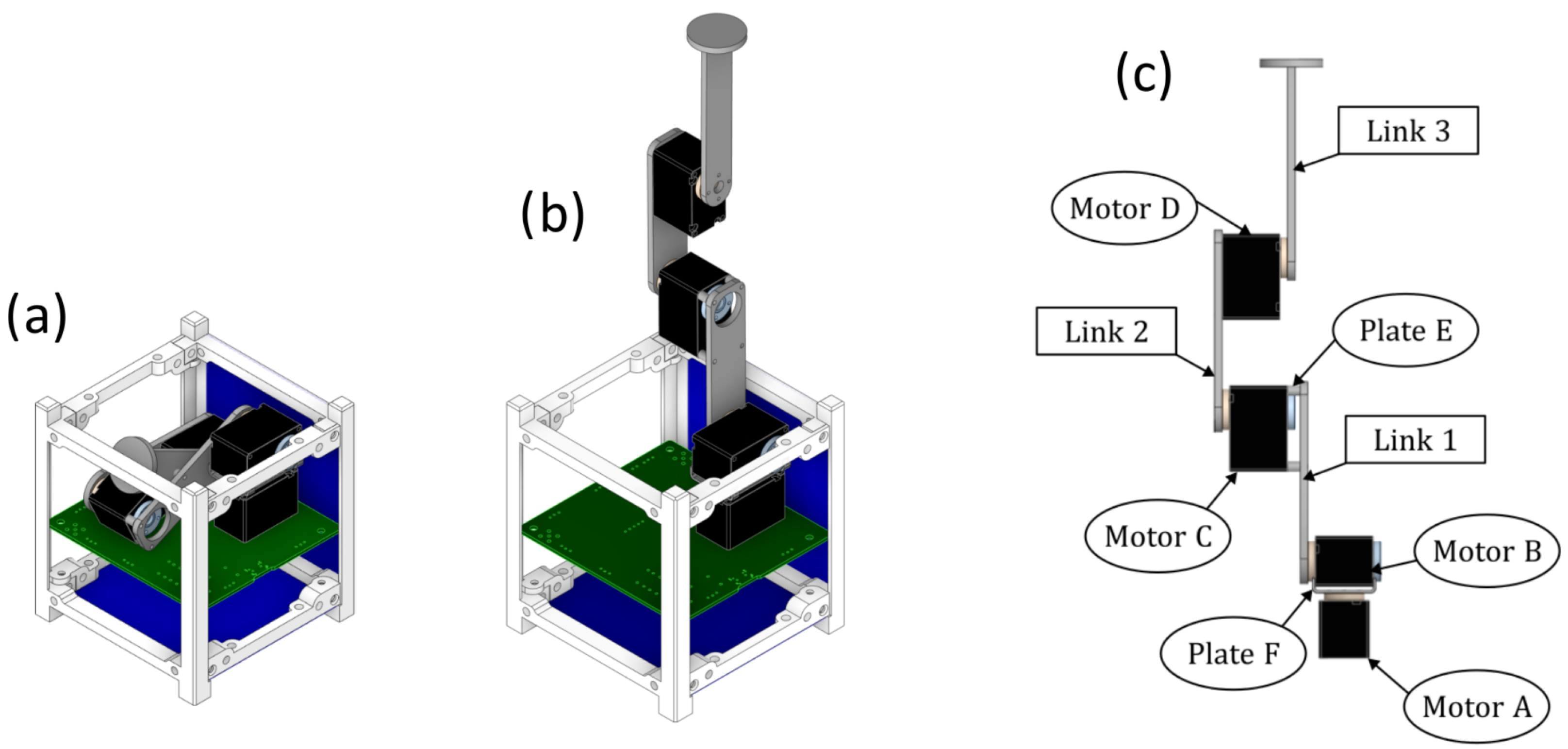
Due to the fundamental physical constraints associated with the arm, which has a maximum storage volume of
cm (corresponding to 0.5 U (half of a CubeSat unit), one of the principal objectives for the manipulator is to be compatible with the 1U form factor of a CubeSat [
23]. This is depicted in
Figure 1a. Another crucial limitation is the mass, which must be less than 0.7 kg. Furthermore, the manipulator design is oriented towards maximizing extension within the given geometric constraints. The precision of the end-effector is contingent upon the motor characteristics and the selected control law, which is determined by the mission requirements of the arm. The arm can extend to a length of approximately
cm and is estimated to weigh around 200 g.
The mechanical design of the C-arm is presented in
Figure 1b. The shoulder joint comprises two motors designated A and B. Motor A serves as the rotating base of the arm, enabling angular rotation. The two motors are connected by a specially designed small aluminium plate, designated as F. Motor B is connected to link 1 by plate E, which has been designed to minimise the volume of the arm when it is stowed. Motor D is integrated into link 2 and drives the movement of link 3, as presented in
Figure 1c. Link 3 is not equipped with a dedicated end-effector, although it is capable of accommodating a variety of elements, including a gripper for a more conventional utilisation of the manipulator or other features such as sensors or small permanent magnets.
2.2. Component and Material Selection
The motors selected to drive the joints were chosen based on a preference for using flight heritage components. The primary challenge was to find a compact motor that could enable dexterous and precise movements for the robotic arm at a low cost. To meet these requirements, Commercial Off-The-Shelf (COTS) elements were used. The chosen motor type was the XC330-M288-T from the ROBOTIS Dynamixel-X series that is part of the Dynamixel-X series produced by ROBOTIS, Seoul, South Korea.
These servomotors are frequently used in robotic manipulators due to their integrated features, which include a DC motor, encoder, microcontroller, sensors, gear reduction, and network connection in every model.
This motor type is a coreless DC motor known for its improved efficiency, reduced weight and size, low inertia, precise motion, and reduced power consumption. The motor type is equipped with a full metal spur gear that provides a gear ratio of 288.35:1. It also incorporates an integrated position sensor, specifically the ams AS5601 from ams AG, Premstätten, Austria, contactless absolute encoder, which provides steps of positioning accuracy.
The microcontroller used is the ARM CORTEX-M0+ from STMicroelectronics, Geneva, Switzerland, which is controlled by a PID controller. The use of a servomotor is advantageous, as it eliminates the need for a separate brake mechanism to hold the joints in place.
3. Satellite and Environmental Model
The conventional approach to modelling satellite orbital and attitude dynamics is to solve the equations of motion while accounting for a range of environmental effects. The dominant force acting on a satellite orbiting in LEO is the gravitational attraction of the Earth. Minor effects are those associated with atmospheric drag, solar radiation pressure, and the luni-solar perturbation. A comprehensive overview of these factors can be found in [
24]. Attitude dynamics for a microsatellite can be conveniently modeled assuming that the spacecraft is a rigid body that follows the Euler dynamic equations of motion [
25]. Environmental factors exerting influence on the satellite’s attitude include gravity gradient, aerodynamic, magnetic, and solar radiation pressure torques. Wertz et al. (2012) provided a comprehensive analysis of the modelling, mitigation, and management of these factors to ensure precise attitude determination and control [
26].
By solving these equations with the inclusion of environmental effects, it is possible to accurately predict and manage the behavior of satellites in space, ensuring their successful operation and fulfillment of the assigned mission. Mathematical models are typically implemented in software such as Matlab version R2025a or Python version 3.13.0 for the purpose of studying the motion of satellites and developing control techniques. In this context, a CubeSat is represented as a 6-DoF rigid body with the capacity to rotate about its principal axes of inertia.
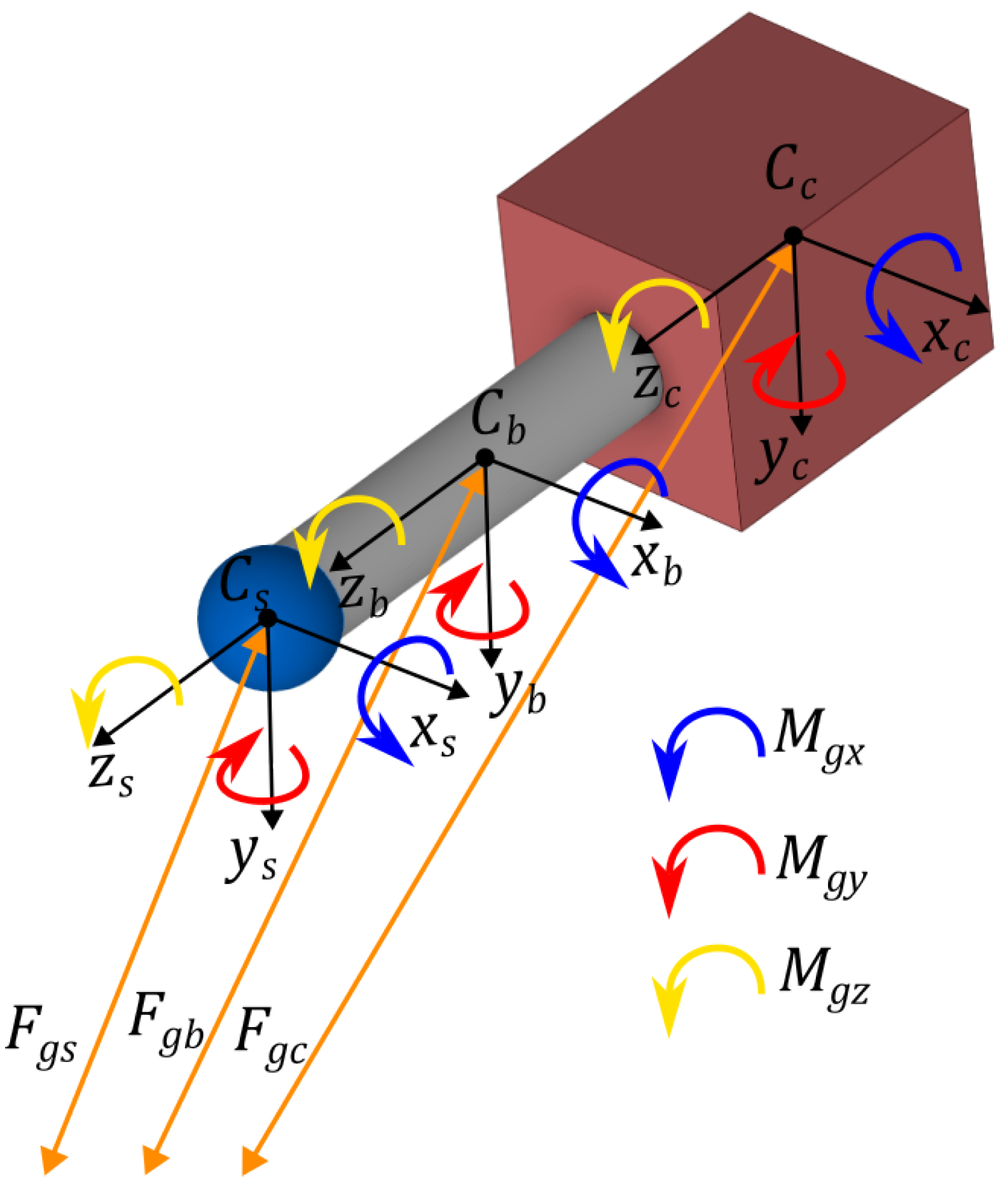
In order to describe the satellite orbit and attitude, three commonly used reference frames are employed. The first reference frame is the Earth-Centered Inertial (ECI, ) frame, which is an inertial frame with the origin set at the center of the Earth with the x-axis pointing towards the vernal equinox, the z-axis parallel to the Earth’s spin axis, and the y-axis completing the orthogonal frame.
In order to define the attitude propagation of the satellite, it is necessary to introduce two reference systems. The first of these is integral with the satellite but fixed with respect to the orbit, while the second describes the satellite’s current behaviour. The former is designated as the Orbit (
) frame, centered at the spacecraft’s center of mass with the z-axis pointing towards the Earth’s center, the y-axis parallel and opposite to the orbit’s angular momentum vector, and the x-axis completing the left-handed triplet. It is worth noting that for a circular orbit the x-axis is always parallel to the orbital speed. The remaining reference frame is designated the Body (
) frame. This frame is situated at the spacecraft’s center of mass, and its axes are aligned with the primary inertial axes of the satellite. The various reference frames are illustrated in
Figure 2.
The orbit is determined by orbital mechanics, while the rotation can be described in an inertial frame centered on the center of mass, as shown in (
2). Here,
represents the total angular momentum, while its derivative with respect to time is the sum of the external perturbation torques and control torques
. This work exclusively models perturbative effects arising from the action of gravity, specifically the gravity gradient torque (
) and the effects of the Earth’s magnetic field that generate the magnetic disturbance torque (
):
Only these disturbance effects were modelled, as our simulations were carried out at an altitude where drag effects can be ignored.
Recalling the classical expression of the time derivative of angular momentum
Euler’s equation, designated as Equation (
3), is formulated with respect to the
reference frame. The angular velocity of the
frame with respect to
is as follows:
where
is the angular velocity of the satellite body axis
with respect to the
reference frame and
is the angular velocity of
with respect to
.
The angular displacement of the satellite (
) from the desired attitude, represented here by (
), can be expressed in terms of the three Euler angles: roll (
), pitch (
) and yaw (
), as in
Figure 2.
3.1. CubeSat and C-Arm Multibody Model
In addition to the utilisation of precise mathematical models to characterize the dynamics of the satellite and evaluate the performance of the orbit control system, multibody simulation can be a valuable tool for investigating the coupled evolution of the satellite’s orbit and attitude without the necessity for a two-phase approach, including the execution of complex tasks such as robotic manipulator movements. The equations of motion are solved directly, and any kind of perturbation can be readily implemented. In this context, the complex system comprising the CubeSat satellite and C-arm is modelled in ADAMS/View and depicted in
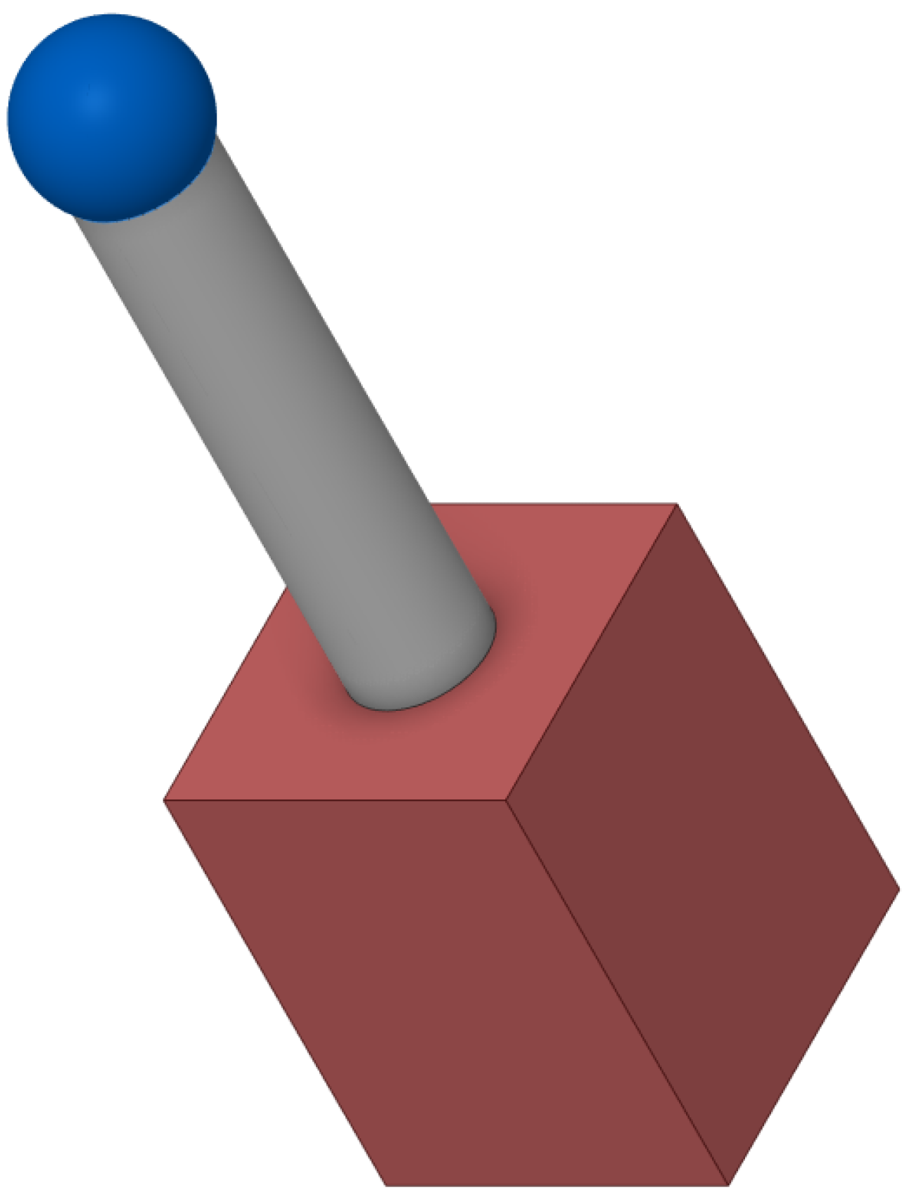
Figure 1. As illustrated in
Figure 1, the satellite and C-arm were decomposed into three rigidly constrained bodies. These bodies serve to identify the three main components depicted in
Figure 3. The cube represents the structure of the 1U CubeSat, the cylinder simplifies the C-arm in full extension, and the final sphere represents the potential end-effector of the C-arm.
The three rigid bodies depicted in
Figure 3 are constrained from moving independently with a fixed joint. This configuration results in a system that behaves as a rigid body with a total of six degrees of freedom. To ensure that the mass properties of the real system are accurately represented, the mass and inertia moments synthesized in
Table 1 were respectively assigned to each body at the corresponding center of mass.
It is important to note that this multibody model represents a preliminary simplification to assess the fundamental feasibility of the C-arm’s influence on attitude dynamics. While it accurately captures the overall mass and inertia properties, it intentionally simplifies the internal complexities of the robotic arm, including individual joint flexibilities and detailed kinematic constraints beyond fixed connections. This approach allows us to obtain a foundational understanding of the coupled system’s behavior under the influence of environmental torques before proceeding to more intricate and computationally demanding models.
3.2. Orbit Description and Initial Condition of Motion
This paper presents a case study that evaluates the evolution in time of a satellite’s attitude in the presence of a gravity gradient. The presented simulations are based on the orbital parameters described in
Table 2. To guarantee the satellite’s movement along the prescribed orbit in the multibody simulation, the gravitational attraction force between the CubeSat and the Earth was incorporated into the ADAMS/View model. Equation (
5) illustrates the translational equation of motion, with the solution referred to as the classical solution to the two-body problem:
where
m
3 kg
−1 s
−2 is the gravitational constant,
M and
are the respective masses of the Earth and the satellite,
is the satellite’s position in
and the double dot indicates the double derivative in time. As previously stated in
Section 3, the satellite’s orbit is subject to environmental disturbances; however, for the sake of simplicity these are not considered in this particular case study.
The CubeSat attitude is employed as the study parameter, which is fully delineated by the Euler angles of roll (
), pitch (
), and yaw (
) describing the deviation of the
with respect to the
. Furthermore, we work under the hypothesis that the initial angular rates reported in
Table 3 are equal to zero. The initial velocity conditions are presented in
Table 3.
Table 2 illustrates that a circular posigrade orbit has been selected, with randomly generated values for the Right Ascension of the Ascending Node (RAAN) and the argument of the perigee.
5. Implementing the Action of the Earth’s Magnetic Field on Attitude
The outcomes of the investigation conducted in
Section 4.2 employing passive gravity gradient control demonstrates that the robotic manipulator is unable to orient the CubeSat to the predefined target using only this tool.
This subsequent step ascertains whether the incorporation of a magnetic passive control system can enhance the satellite’s attitude. The objective is to utilize the manipulator to orient permanent magnets in accordance with the CubeSat’s desired orientation. The magnets are positioned in a slot specifically designed for this purpose and located in link 3 of the robotic manipulator, as illustrated in
Figure 9.
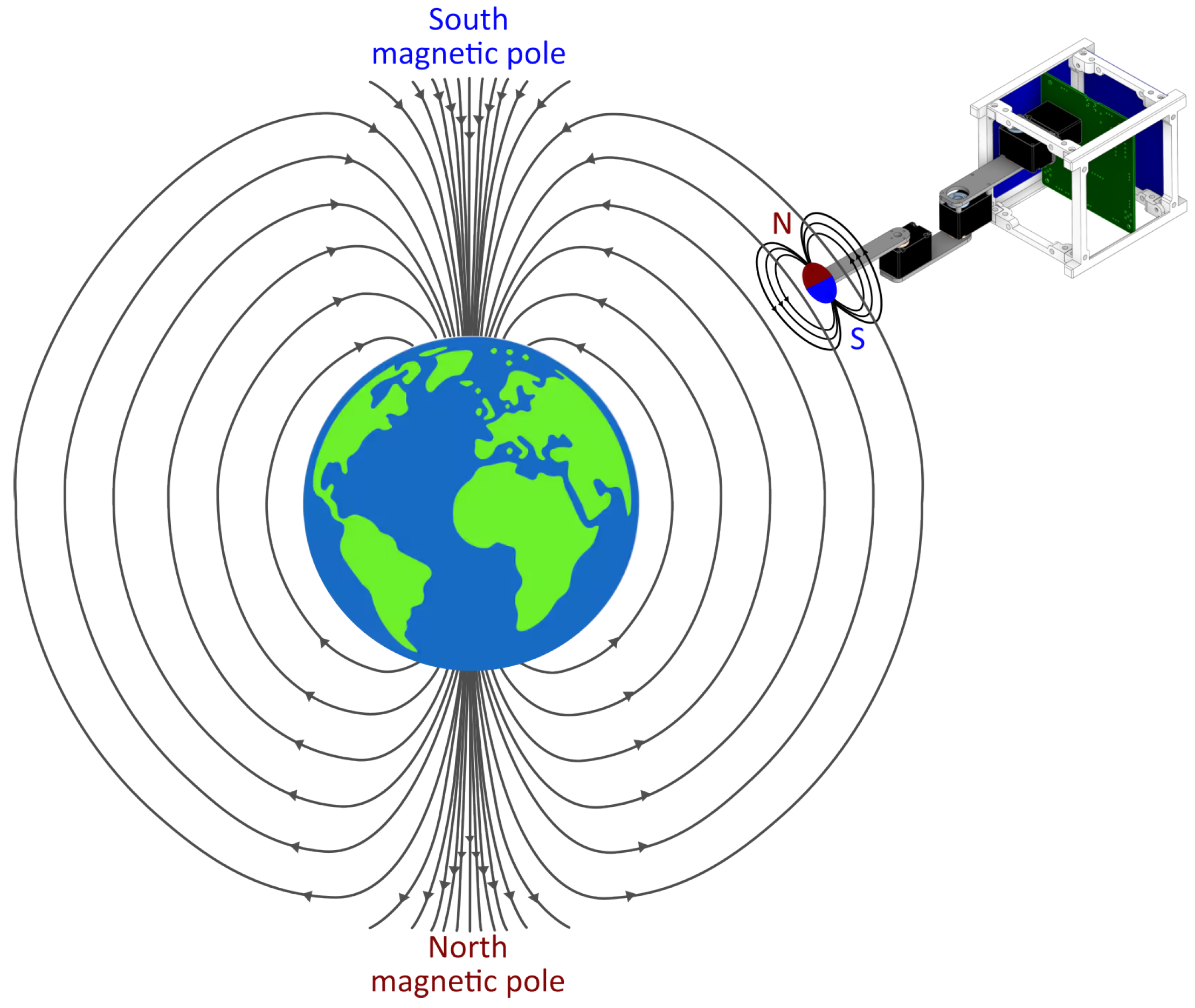
The selection of permanent magnets was based on their reliability in maintaining uniaxial attitude control. This is due to their high magnetic moment, which aligns the satellite with the tangent of the Earth’s magnetic field. For communication purposes, uniaxial orientation is sufficient.
Based on previous research [
28], four cylindrical neodymium magnets with external and internal diameters of 7 mm and 3.4 mm, respectively, and a height of 11.5 mm are placed on the corresponding plate to create a magnetic field in link 3 of the C-arm. Each magnet has a dipole moment of
0.3095 Am
2 along the axis of symmetry, while the radial component is negligible.
The magnetic torque is a consequence of the interaction between the Earth’s magnetic field and the satellite’s magnetic dipole moment.
In addition to the dipole moment of the permanent magnet, the effect of residual magnetic disturbances in the CubeSat must be considered. The effect of all these magnetic moments is denoted as
in Equation (
7).
The Earth’s magnetic field, designated as
in Equation (
7), is represented by the International Geomagnetic Reference Field-13 (IGRF-13) model. It was necessary to recreate the model in the ADAMS multibody software, although the geomagnetic field model is fully defined in [
29] and there are numerous programs and software that implement it.
The IGRF describes the main geomagnetic field
as the gradient of a scalar potential
and the potential (
8) as a finite series expansion in terms of spherical harmonic coefficients
,
, also known as Gauss coefficients:
where
refer to coordinates in a geocentric spherical coordinate system (
), with
r as the radial distance from the Earth’s center and
respectively representing the geocentric latitude and longitude. A reference radius
6371.2 km is chosen to approximate the mean radius of the Earth. Here,
are Schmidt semi-normalised associated Legendre functions of degree n and order m. The parameter N indicates the maximum degree of spherical harmonic expansion. For the objectives predicted for this work, the series expansion was stopped at the first order, obtaining the potential of the dipole model of the geomagnetic field (Equation (
9)):
The components of
B are provided in Equation (
10) with respect to a geocentric non-inertial coordinate system. The Gauss coefficients for the year 2023 are shown in
Table 8.
Equation (
10) expresses the Earth’s magnetic field in a non-inertial geocentric frame of reference. It should be noted for the sake of completeness that to calculate the magnetic external torque it is first necessary to transform the
B component to the body reference frame
. The magnetic moment of the magnets is designated as
, as illustrated in
Figure 10, and calculated in accordance with the methodology outlined in Equation (
7).
5.1. Multibody Implementation
To incorporate the resulting moment caused by the interaction between the Earth’s magnetic field and the satellite’s dipole moment, an update to the model presented in
Section 4.1 is required. In an initial step, we assessed the magnitude of the magnetic perturbations acting on the satellite. The satellite is equipped with electronic components, including circuit boards, robotic arm motors, and batteries, which are sources of magnetic perturbations and are modelled as a dipole moment. The study parameter we employed was the dipole moment (
), with the reference values provided in
Table 9. The parameters were selected with a degree of conservatism, using values generally in excess of the actual order of magnitude of the CubeSat’s dipole moments. The moment acting on the body due to this perturbation, denoted as
, is applied to the center of mass (CoM) of the CubeSat and calculated in a manner analogous to that described in Equation (
7).
It was anticipated that the simulations presented in
Section 5.2 would be illustrated only with the perturbation defined in Test 2, since the effect of the magnet is stronger than that of the residual dipole effects. Therefore, the results of every test of
Table 9 are very similar. After defining the action of the magnetic perturbation torque and the action of the permanent magnet torque, we integrated these torques into the multibody model, as illustrated in
Figure 10.
Simulations were performed using the orbit described in
Section 4.1, as previously; however, the initial conditions of the attitude (provided in
Table 10) differed from those used in the case of gravitational control. In this case, we assumed ideal initial conditions of motion at equilibrium.
In this way, the magnetic moment effect was incorporated into the simplified multibody model. At this stage, the model incorporates the effects of both the gravity gradient torque and the magnetic moment.
5.2. Final Results
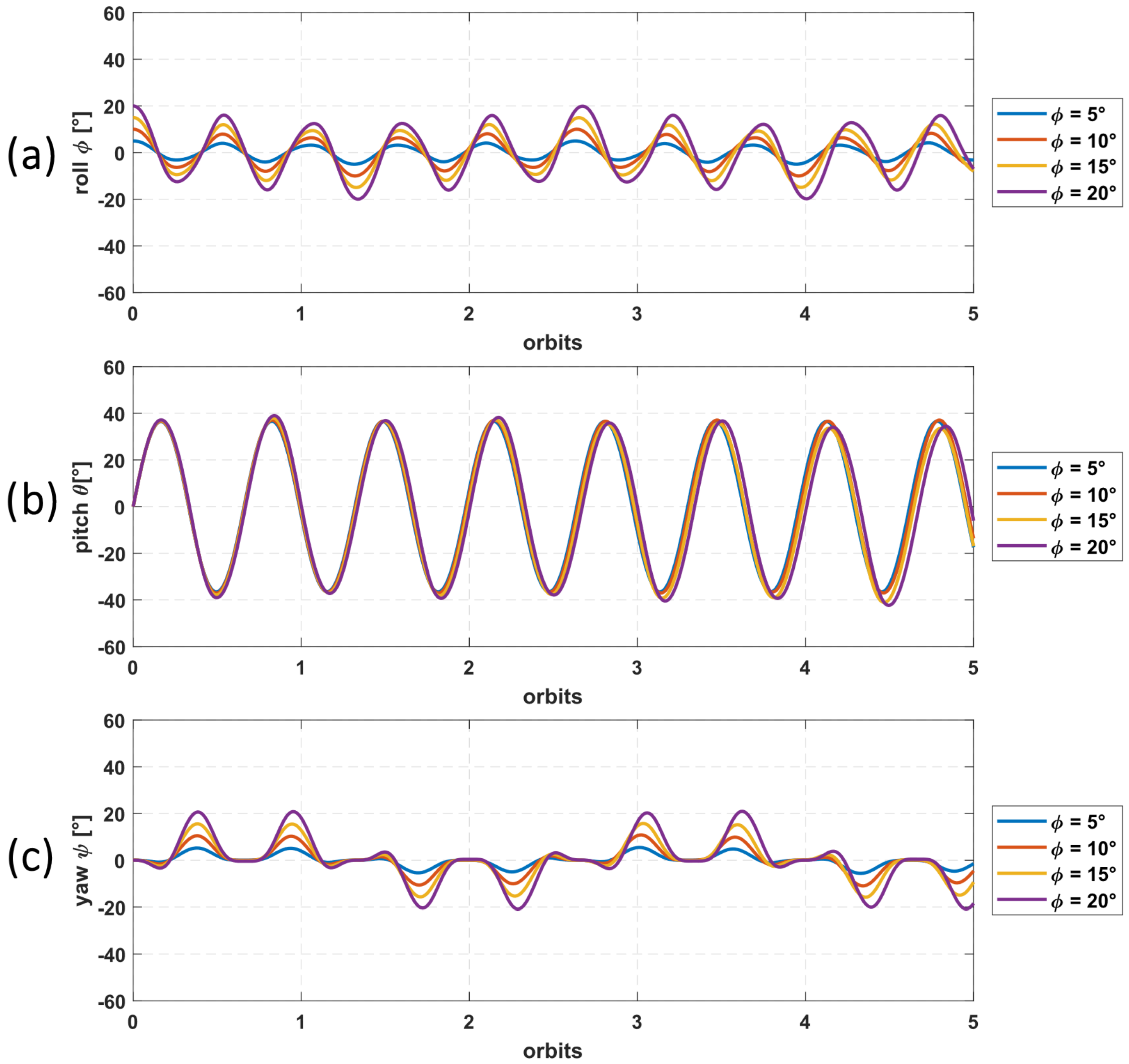
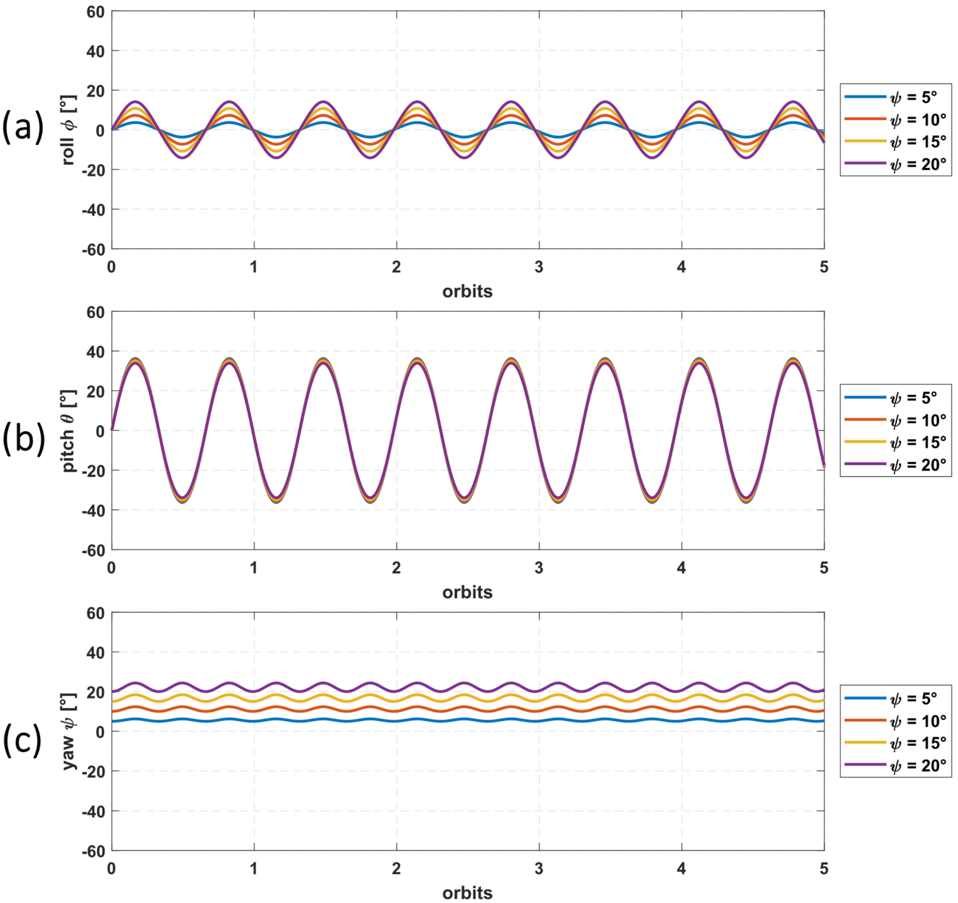
The simulations utilizing a permanent magnet revealed a complex and predominantly unstable attitude behaviour. While the magnet is intended to provide a pointing mechanism, the results (particularly those shown in
Figure 11c) indicate the induction of unstable rotation around the z-axis (yaw angle
). Quantitatively, yaw oscillations frequently exceeded
. Similarly, pitch oscillations continued to exhibit amplitudes in the range of
and roll oscillations frequently exceeded
, as is visible in
Figure 11a,b. This widespread instability across multiple axes stems from the tight coupling of rotations inherent in the Euler equations (Equation (
3)). Consequently, instability originating or amplified in any one axis is propagated, causing the pitch and roll angles to exceed the desired limits.
A critical and distinct quantitative observation from these simulations is the emergence of significantly higher-frequency oscillations superimposed on the underlying low-frequency gravity gradient motion, which is particularly noticeable in
Figure 11a,c. These rapid oscillations, with periods observed to be on the order of a few tens of seconds (markedly shorter than the orbital period of approximately 90 min), are a direct consequence of the permanent magnet’s continuous and rapid attempt to align with the dynamic local geomagnetic field. This active interaction introduces additional kinetic energy into the system, emphasizing the critical need for robust damping mechanisms that can dissipate this induced energy and achieve stable pointing.
6. Conclusions and Future Work
The objective of this study was to evaluate the effectiveness of utilising a robotic arm as a passive device to control the attitude of a microsatellite. In particular, a robotic arm that is compatible with a 1U CubeSat, designated the C-arm, was developed in this study. The compact dimensions of the robotic arm imposed notable constraints in terms of size and weight (the latter reaching 200 g). This was particularly evident in the maximum extension length of the arm, which when retracted occupied 0.5 U. Subsequently, simulations of attitude propagation conducted using a simplified multibody satellite model demonstrated the efficacy of this innovative approach as a tool for achieving the objectives of this research activity. The effectiveness of two passive actions on the satellite’s attitude control was evaluated: the gravitational effect produced by the extended arm, and the action of the Earth’s magnetic field when a permanent magnet was introduced at the end of the C-arm.
The results of simulations that exclusively considered the gravitational effect demonstrated that despite the small size of the robotic arm, its influence on the temporal evolution of the satellite’s attitude motion as a consequence of the torque exerted by the gravitational gradient is not negligible. Our results showed that even though the effects of this external torque are negligible for a 1U CubeSat (and for compact microsatellites in general), this is not the case when the C-arm linked with the satellite is completely deployed. In particular, we found that when the initial conditions vary, the pitch angle always oscillates at a low frequency around . The roll and yaw angles exhibit a more variable trend but always at low frequency, with maximum values lower than the pitch angle at and . These results, while significant for a 1U CubeSat, suggest that a purely passive gravity gradient approach with this C-arm configuration may be suitable for missions with less demanding pointing accuracy requirements, as is typical of many nanosatellite applications.
In a subsequent step, we incorporated the effect of the Earth’s magnetic field on the satellite’s attitude. This was achieved by exploiting a permanent magnet to reduce the pitch angle and achieve improved pointing. The interaction provides a magnetic dipole moment parallel to the longitudinal axis of the robotic arm (in an extended position), ensuring a three-dimensional attitude motion even when the initial value of the Euler angles and angular rates are null. The pitch, roll, and yaw angles do not exhibit significant maximum value variations; however, the magnetic interaction results in high-frequency oscillations of all the Euler angles, which overlap with the low-frequency oscillations associated with the gravity gradient torque. Consequently, the aforementioned desired attitude is established in a shorter time frame. Notably, we observed a temporary reduction in pitch oscillations with the use of magnets.
In conclusion, the results of this study prove that integration of a robotic arm into a CubeSat has a strong influence on the attitude motion of the satellite, and as such can be considered as a valid and effective tool to passively control the attitude of the CubeSat with medium/high accuracy of the pitch angle.
Limitations and Future Developments of the Study
This preliminary study offers valuable insights into using a robotic arm for passive CubeSat attitude control. However, it is essential to acknowledge several inherent simplifications which define its current scope. Our multibody model of the C-arm simplifies its structure (representing it as a rigid cylinder and sphere) and neglects detailed joint flexibilities. Crucially, the model also excludes significant dissipative forces such as atmospheric drag, solar radiation pressure, and internal damping, which are vital for achieving stable and settled attitudes in real-world scenarios. In addition, this work focused exclusively on passive control and explored a limited range of initial conditions and scenarios.
These limitations highlight the foundational nature of this research. Future work will directly address these aspects. We plan to refine our multibody models to incorporate more detailed CubeSat and arm characteristics, including joint flexibilities. In addition, we will introduce mechanisms such as soft magnetic devices for dissipating rotational kinetic energy in order to achieve stable oscillations. Further research will expand the analysis in this paper to include other environmental disturbances such as atmospheric drag and solar radiation pressure as well as to explore active control strategies using the robotic arm, potentially integrating magnetic coils or controlled movements for precise pointing and disturbance rejection. Lastly, we aim to investigate a wider range of orbital conditions and C-arm configurations in order to assess its robustness and adaptability.


 ,
, 


