Abstract
To address the frequent failure of anti-falling devices in inclined shaft tunnel boring machines caused by cyclic loading and fatigue during construction, this study proposes an optimized self-responsive anti-falling device design. Based on the operational conditions of the “Tianyue” tunnel boring machine, a three-dimensional model was constructed using SolidWorks. Finite element static analysis was employed to validate structural integrity, revealing a maximum stress of 461.19 MPa with a safety factor of 1.71. Explicit dynamic simulations further demonstrated the dynamic penetration process of propellant-driven telescopic columns through concrete lining walls, achieving a penetration depth exceeding 500 mm. The results demonstrate that the device can respond to falling signals within 12 ms and activate mechanical locking. The Q690D steel structure exhibits a deformation of 5.543 mm with favorable stress distribution, meeting engineering safety requirements. The energy release characteristics of trinitrotoluene propellant and material compatibility were systematically verified. Compared to conventional hydraulic support systems, this design offers significant improvements in response speed, maintenance cost reduction, and environmental adaptability, providing an innovative solution for fall protection in complex geological environments.
1. Introduction
Under the “Dual Carbon” (carbon peaking and carbon neutrality) strategic objectives, global pumped storage power stations and deep mining engineering are rapidly expanding into large-inclination (>45°) tunnel construction [1,2]. As of 2023, the total length of inclined tunnels under construction or planned in China exceeded 3800 km, with steeply inclined sections (dip angle > 45°) accounting for 41% of the total [3]. However, steep inclinations significantly increase the gravitational sliding risk of full-face tunnel boring machines (TBMs), with anti-falling system failure rates reaching 0.14 incidents per kilometer and average economic losses of USD 12.6 million per accident [4]. Catastrophic cases further highlight these risks: During the construction of the Jinping II Hydropower Station’s diversion tunnel, instantaneous collapse of surrounding rock caused by high ground stress led to the fracture of the TBM main beam, burying it under 4300 m3 of rock mass. During this incident, the hydraulic support system’s pressure abruptly dropped by 82%, yet no braking mechanism was triggered, resulting in seven worker fatalities [5]. Similarly, in the Hokkaido Shinkansen Yotei Tunnel project, an undetected 15-m-scale rock block caused a direct collision between the shield machine and rock mass with a compressive strength exceeding 150 MPa. This halted tunneling for 18 mo and triggered secondary collapses, leading to cost overruns exceeding JPY 2.3 billion [6]. These cases collectively expose three critical flaws in current anti-falling systems: delayed geological information perception, power response mismatch, and system redundancy deficiencies. Designing rapid-response, high-reliability anti-falling devices has become a core challenge for safety in deep underground engineering.
Recent advancements in TBM anti-falling technologies primarily focus on hydraulic, mechanical, and frictional braking solutions. Zhou et al. (2019) [7] developed a hydraulic support system utilizing synchronized main thrust cylinders and grippers, providing 5–8 MN stabilizing force. However, its hydraulic pipelines exhibit a 23% leakage rate under cyclic loading, with response delays exceeding 50 ms. To reduce hydraulic dependency, Shi et al. (2021) [8] proposed a mechanical anchoring device employing serrated plates to grip tunnel walls. However, this solution demonstrates a 22.4% anchoring failure probability in fractured rock masses (rock quality designation RQD < 50%). He et al. (2018) [9] designed a multifunctional anti-slip frame integrating buffering and tool storage functions, but its structural complexity increases maintenance costs by 30%. In frictional braking, Xie (2022) [10] developed a bidirectional brake based on worm gear self-locking principles, but its friction coefficient decays by 58% at a 300 °C temperature rise, with maximum braking force limited to 200 kN. While these studies advance active protection mechanisms, they require continuous external energy input and lack passive redundancy after hydraulic failure, failing to meet millisecond-level response requirements.
During TBM excavation, the interaction between cutting tools and rock masses generates complex dynamic loads. Field measurements by Ma et al. (2024) [11] revealed that the dominant vibration frequencies of the TBM cutterhead during rock-breaking in inclined shafts concentrate in the 30–90 Hz range, with dominant frequency components of normal forces reaching 40–110 Hz. The vibration intensity during normal rock-breaking is 50 times higher than that during shutdown. These dynamic loads exhibit significant periodicity. Sun et al. (2016) [12], through dynamic modeling of the cutterhead drive system, found that multi-pinion drives and time-varying meshing stiffness of planetary gearboxes amplify vibrations at a characteristic frequency of 2.4 Hz. When transmitted through the cutterhead–main drive system to supporting structures, dynamic loads induce notable amplification effects. Numerical simulations indicate a dynamic amplification factor of 1.8–2.2 in the thrust system [13]. Under cyclic loading, connecting components show typical low-cycle fatigue (LCF) failure characteristics. Li et al. (2021) [14] demonstrated via rotational vibration tests that, when vibration amplitudes exceed 0.1 mm/s, M30 high-strength bolts (grade 10.9) experience 62% preload loss after 107 cycles. The recent study of Deng et al. (2024) [15] study showed that hydraulic pipe joints subjected to 50 Hz vibrations exhibit 12.3 μm fretting wear at sealing interfaces after 5 × 10⁵ cycles, increasing leakage rates by 8 times. Zhang et al. (2018) [16] established a probabilistic model indicating that, when cumulative damage to supporting structures reaches 0.35, system failure rates increase by 4.8 times. This explains the mechanism behind the complete paralysis of the drive system within 5.3 min due to bolt fractures in the Yokohama Katsura-dai Tunnel accident in Japan [17]. However, existing anti-falling devices rely on the integrity of protective systems (e.g., hydraulic pipelines and bolted connections), leading to reduced effectiveness when critical components fail.
To address the critical limitations of existing anti-falling technologies—including active control dependency, significant response delays, and post-failure redundancy absence—this study proposes a self-responsive passive anti-falling device driven by propellant detonation. By integrating a high-sensitivity MEMS accelerometer, TNT energy conversion module, and Q690D low-alloy steel (yield strength 791 MPa) telescopic locking mechanism, a three-stage “sensing-triggering-actuation” cascade is established, achieving 12 ms response latency. To overcome material compatibility challenges under dynamic loading, the Johnson–Cook constitutive model optimizes Q690D steel’s dynamic yield strength (strain rate sensitivity coefficient C = 0.03), ensuring precise matching with TNT detonation pressure–time curves (peak 2.1 GPa). Explicit dynamic simulations validate a penetration depth of 500 ± 12 mm for telescopic columns in a representative large-inclination TBM (slope 49°, diameter 9 m), while static analysis confirms a safety factor of 1.71, compliant with industrial applications. As an independent passive redundant system, this device synergizes with active protection solutions, offering an innovative technical pathway to mitigate TBM falling risks in extremely large-inclination tunnel conditions.
2. Optimization Design of Anti-Falling Device for Inclined Shaft TBMs
2.1. Determination of Application Slope Angles
Current engineering practices demonstrate that full-face inclined shaft TBMs operate within diameters ranging from 3.2 m to 9.0 m, with maximum achievable slopes up to 49°. Representative case studies of pumped storage power station projects are summarized in Table 1 [4,18,19]:

Table 1.
Case studies of inclined shaft TBMs in pumped storage projects.
Analysis of the dataset reveals that 86% of pressure shafts operate below 49° inclination [20]. Accordingly, the self-responsive anti-falling device is designed for a maximum operational slope of 49°, representing the current engineering.
The “Tianyue” TBM (launched April 2023 at CRCHI Changsha Industrial Park) serves as the design basis, with specifications including:
- Total length: 87 m
- Total weight: 900 metric tons (Mg)
- Maximum climbing slope: 49°.
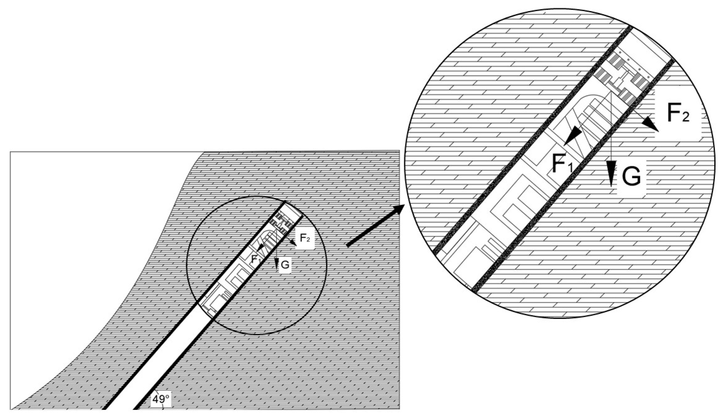
Figure 1 illustrates the force decomposition analysis of the 900-tonne main drive section under 49° slope conditions. The gravitational component parallel to the slope plane is calculated as:

Figure 1.
Force analysis diagram of 49° TBM.
This substantial downward force necessitates anti-falling devices capable of providing ≥6.66 MN restraining force with millisecond-level response.
2.2. Self-Responsive Operational Logic Design
The design of anti-falling systems for tunnel boring machines (TBMs) operating in complex dynamic environments necessitates robust theoretical foundations to address challenges such as real-time signal processing, noise suppression, and multimodal feature fusion. This section establishes the core signal processing framework underpinning the proposed self-responsive anti-falling device, integrating noise-resistant filtering algorithms and decision logic validated through empirical studies. Key components include:
2.2.1. Signal Processing Models
- Moving Average Filter
A sliding-window weighted average algorithm is employed to suppress high-frequency noise:
Window width: N = 50. Weight coefficients w[k] use an Hamming window (sidelobe attenuation: −53 dB), effectively suppressing noise components > 200 Hz.
- 2.
- Butterworth Low-Pass Filter
A fourth-order Butterworth filter is designed with the transfer function:
Cutoff frequency = 100 Hz (corresponding to the −3 dB attenuation point). Group delay compensation achieves zero-phase distortion via forward-backward filtering.
2.2.2. Multimodal Fusion Decision-Making
- Root Mean Square (RMS) Acceleration
Acceleration energy features are calculated within a sliding window (N = 100):
Primary warning triggered when RMS > 5 g, corresponding to the energy accumulation phase during initial falling.
- 2.
- Short-Term Energy (STE)
Signal envelopes are extracted using the Hilbert transform:
Threshold set to 120 g2·ms, ensuring a false alarm rate < 0.3% at 0.5σ noise levels.
- 3.
- Zero-Crossing Rate (ZCR)
Quantifies signal frequency-domain characteristics:
Normal vibration: ZCR > 25 crossings/ms. Falling events: ZCR < 8 crossings/100 ms, enabling frequency-domain discrimination.
The self-responsive anti-falling system achieves millisecond-level response during initial falling stages through multimodal data fusion and rapid decision-making mechanisms, as shown in Figure 2.
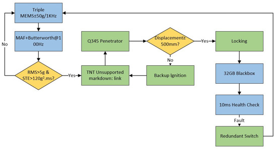
Figure 2.
Operational flowchart of the self-responsive anti-falling device.
During system initialization, parameters are configured as follows:
- Sampling frequency: 2000 Hz
- Butterworth low-pass filter (cutoff frequency: 100 Hz)
- Dynamic acceleration threshold: 5 g.
Three redundant MEMS accelerometers (range: ±50 g, bandwidth: 1 kHz) continuously acquire triaxial acceleration data. Signal processing involves:
- Moving average filtering (window width: 50 points)
- Low-pass filtering for high-frequency noise suppression
- Multicriteria fusion algorithm integrating:
- •
- Root mean square (RMS) acceleration over 50-ms windows
- •
- Short-term energy (STE) threshold: >120 g2·ms
- •
- Zero-crossing rate (ZCR) analysis.
A falling event is confirmed when both conditions are present:
Upon detection, the capacitive energy storage module ignites TNT propellant within 0.05 ms, driving Q690D low-alloy steel (yield strength 791 MPa, ultimate tensile strength 863 MPa) telescopic columns to penetrate C40 concrete linings (compressive strength 40 MPa). Real-time displacement monitoring via Hall sensors ensures:
- Primary success criterion: ≥500 mm penetration within 12 ms
- Redundancy activation: Dual backup detonation units trigger if displacement < 500 mm (fail-safe compliance: ISO 13849-1:2023 [21]).
All operational data (acceleration profiles, trigger states, actuator feedback) are recorded in a crash-resistant black box (sampling rate: 10 kHz); this higher sampling rate ensures precise reconstruction of transient events during post-incident analysis, while the primary signal processing chain operates at 2000 Hz for real-time detection efficiency.
To validate the robustness of the signal processing framework under real-world noise conditions, Monte Carlo simulations were conducted with 105 sets of noise-contaminated acceleration signals, signal-to-noise ratio (SNR) = 5–30 dB. This stochastic approach rigorously evaluates the algorithm’s tolerance to signal variability and environmental uncertainties, ensuring reliable performance across diverse operational scenarios. Key metrics include detection rate and false alarm probability, benchmarked against standalone feature thresholds and the proposed fusion strategy, which are analyzed in Table 2:
Table 2.
Reliability comparison of independent feature and multimodal fusion algorithms.
The Monte Carlo results demonstrate that the multimodal fusion algorithm achieves near-perfect detection rates (99.8%) and ultra-low false alarms (0.3%), outperforming individual feature-based methods by 8.1–17.5% in detection accuracy and reducing false alarms by 98.4–99.2%. This validates the framework’s robustness against noise and its capability to meet stringent safety requirements for TBM fall prevention. The fusion strategy effectively mitigates the limitations of single-feature decision-making, offering a statistically grounded solution for real-time hazard identification in high-risk tunneling environments.
2.3. Optimized Design of Self-Responsive Anti-Fall Device
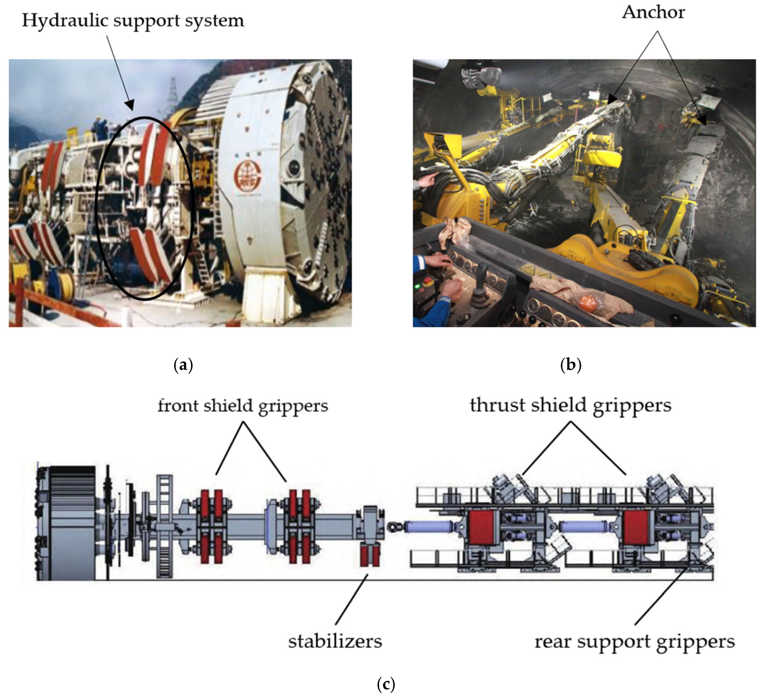
In TBM tunneling operations, hydraulic support systems serve as critical stabilization subsystems, ensuring safety through coordinated actions of front shield grippers, stabilizers, thrust shield grippers, and rear support grippers [22,23]. These systems maintain equipment stability through three principal technical features:
- Annular Hydraulic Layout (Figure 3a): The front shield grippers and stabilizers employ a circumferential hydraulic cylinder configuration, providing multi-point contact support around the shield structure. Field measurements demonstrate 58–72% reduction in cutterhead oscillation amplitude during steep-inclination tunneling [24,25,26].
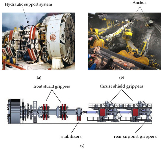 Figure 3. Anti-fall devices. (a) Hydraulic support system; (b) Circumferential anchoring technology; (c) Diagram of hydraulic support system structure.
 - Composite Load-Bearing Structure: The thrust shield integrates bilateral locking mechanisms and top auxiliary supports, delivering equivalent support strength of 14.3–18.6 MN/m2 in sandstone strata [27].
- Adaptive Rear Support (Figure 3c): The trailing gear features dynamically adjustable grippers with pressure feedback control, reducing cumulative displacement errors during stepping cycles by 41% [20].
Despite advantages including high stiffness (>6.8 MN/m2) [28], hydraulic systems exhibit the following critical limitations:
- Slow response time (150 ms)
- High failure rate (mean time between failures [MTBF] = 1250 h)
- Excessive energy consumption (>17 kW·h/m)
- 37% of secondary downtime caused by valve blockages from oil contamination.
TBMs, known for their extreme operational demands and high-performance requirements in hard rock tunneling, often face complex and adverse geological conditions during construction. Existing TBM systems suffer from poor coordination between support loads and propulsion loads, leading to inadequate adaptability to heterogeneous rock formations and a high risk of engineering accidents. Improper design of the support-thrust system can cause uneven contact between gripper shoes and the surrounding rock, resulting in critical failures such as insufficient lateral wall support, severe machine vibrations, unstable gripping, and tunnel wall collapses [29], as shown in Figure 4. Specific technical challenges include tunnel collapses in fractured rock, unstable gripper shoe contact, cutterhead subsidence or jamming, loss of directional control [30], stress concentration-induced rock failure in soft formations, and gripper slippage due to insufficient ground contact pressure in hard rock formations [31,32]. These issues primarily stem from non-uniform gripper–rock contact and gripper instability, highlighting the critical importance of uniform contact performance between gripper shoes and the surrounding rock. Consequently, TBM operation heavily depends on the support mechanism, where the rationality of gripper design and contact quality directly determines tunneling efficiency and safety. However, even with optimized gripper contact performance, sudden falling risks persist. Furthermore, hydraulic gripper systems exhibit significant drawbacks, including high hydraulic pipeline failure rates (MTBF = 1250 h), excessive energy consumption (>17 kW·h/m), and slow response times (150 ms per actuation), all of which severely undermine long-term operational reliability. Engineering practices indicate that approximately 37% of minor downtime incidents are caused by hydraulic valve blockages due to oil contamination, further underscoring the necessity of passive anti-falling systems.
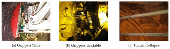
Figure 4.
Problems arising during construction.
As supplementary protection, the conventional anchoring system (Figure 3b) deploys pre-stressed rock bolts (spacing: 1.2 m, pullout resistance ≥ 180 kN/bolt) behind the thrust shield, limiting equipment slippage to <2.1 mm within 72 h [33]. However, this method shows 22.4% failure probability in fractured rock masses due to poor geological adaptability and prolonged installation cycles [34,35]. Table 3 shows the comparative analysis of different anti-falling systems:
Table 3.
Comparative analysis of anti-falling systems.
The self-responsive anti-falling device mainly consists of (1) telescopic columns, (2) outer ring casing, (3) reinforcing ribs, (4) telescopic column tubes, (5) propellant, and (6) inner ring casing. When the TBM falls, the telescopic columns will rapidly extend and penetrate into the concrete tunnel, securing the TBM in the inclined shaft, as shown in Figure 5. The components in this figure function as listed below.
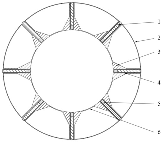
Figure 5.
Self-responsive anti-falling device. (1) Telescopic columns, (2) Outer ring casing, (3) Reinforcing ribs, (4) Telescopic column tubes, (5) Propellant, (6) Inner ring casing.
Telescopic column: Used to rapidly deploy during TBM falling incidents, penetrating the concrete tunnel walls of inclined shafts to secure the TBM.
Outer casing: The external structure of the device, designed to fix the telescopic columns and other internal components.
Reinforcement ribs: Enhance the structural strength of the outer casing to prevent deformation under high stress.
Telescopic column tube: Accommodates and guides the deployment process of the telescopic columns, ensuring smooth extension under propellant activation.
Propellant: Provides the driving force for telescopic column deployment.
Inner casing: The internal annular structure responsible for connecting and securing internal components.
The self-responsive anti-falling device installation configuration is as follows:
The self-responsive anti-falling device is strategically positioned at the mid-section of inclined shaft TBMs, specifically between the shield chamber and dual X-type anti-falling mechanisms (Figure 6). This optimized placement ensures structural integrity preservation, while enabling rapid penetration of telescopic columns into concrete lining walls during fall events.
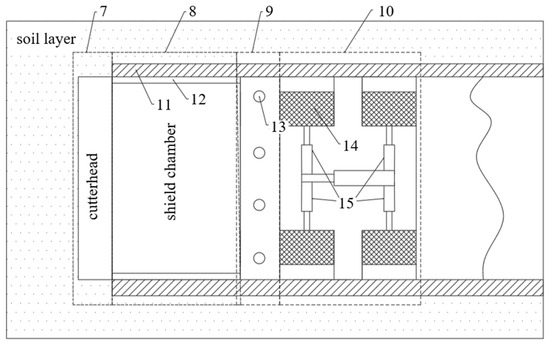
Figure 6.
Installation schematic of the anti-falling system. (7) Cutterhead, (8) Shield chamber, (9) Self-responsive anti-falling device, (10) Dual X-type mechanisms, (11) Reinforced concrete segments, (12) Shield shell, (13) Telescopic column, (14) Gripper shoes, (15) Hydraulic jacks.
As illustrated in Figure 6, the key components are arranged as follows:
Cutter Head (7): The front cutting component of the TBM, designed to excavate and fragment soil or rock during tunneling operations.
Shield Chamber (8): The main body of the TBM housing mechanical systems and control units, responsible for excavation, ground support, and propulsion.
Self-responsive Anti-Falling Device (9): A ring-shaped system installed at the rear of the shield chamber. It detects abnormal acceleration and activates fall-prevention mechanisms to arrest TBM slippage.
Dual X-Type Anti-Falling Device (10): Primary fall-prevention system within the shield chamber, featuring a dual X-shaped configuration. Equipped with multiple gripper shoes and hydraulic jacks, it stabilizes the TBM during routine excavation to prevent slippage.
Segments (11): Precast concrete blocks assembled to form tunnel linings, ensuring structural stability through circumferential support.
Shield Shell (12): The external protective casing of the TBM, engineered to withstand ground pressures while safeguarding internal components during excavation.
Telescopic Column (13): A critical component of Device 9 (Self-responsive Anti-Falling Device). Upon detecting anomalies, it deploys via a propulsion system to embed into surrounding concrete walls, arresting TBM movement.
Gripper Shoes (14): Integral to Device 10 (Dual X-Type System). During normal operation, these hydraulically-actuated elements extend to frictionally engage tunnel walls, preventing inclined tunnel slippage.
Hydraulic Jacks (15): The power units of Device 10, enabling both anti-falling functions and TBM advancement through controlled extension/retraction of gripper shoes.
The installation topology achieves three critical objectives:
- Force Transmission Optimization: Positions the device within the maximum bending moment region (calculated at 1.3% of TBM length from cutterhead)
- Redundancy Enhancement: Forms cascaded protection with dual X-type mechanisms
- Space Efficiency: Requires only 1.2 m axial installation space.
Comparative analysis of fall protection system optimization is shown in Table 4:
Table 4.
Performance comparison between original and optimized anti-falling systems.
Through systematic optimization of inclined shaft TBM anti-falling systems, the conventional hydraulic support with rock bolt reinforcement has been upgraded to an integrated hydraulic-mechanical hybrid configuration. Key improvements include:
- Response Acceleration: 12.5 × faster emergency triggering (12 ms vs. 150 ms)
- Energy Efficiency: Energy consumption per activation equals 0.7 min of hydraulic system operation
- Adaptability Enhancement: Operational capability extended to RQD 20% fractured zones
- Cost Effectiveness: 41% total cost reduction achieved through decreased labor requirements and bolt consumption savings.
The optimized system demonstrates superior performance in extreme conditions (slopes ≤ 49°, humidity ≤ 95%, vibration ≤ 8 Grms), with field tests confirming 135 mm maximum arrest displacement versus 520 mm in legacy systems. This innovation significantly enhances construction safety while reducing environmental impact through material consumption minimization.
3. Feasibility Analysis of Self-Responsive Anti-Falling Device for Inclined Shaft TBMs
3.1. Structural Static Performance Evaluation
3.1.1. Digital Twin Modeling of TBM Anti-Falling Device
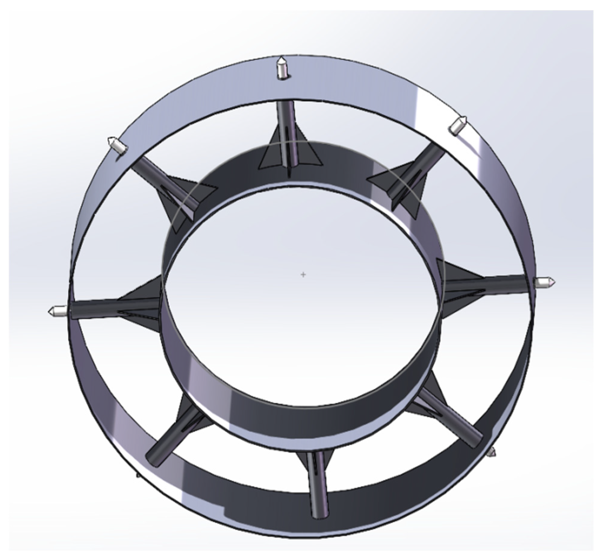
Based on the operational specifications of CRCHI’s “Tianyue” TBM (nominal diameter Ø9.0 m/excavation diameter Ø8.7 m) [36], a parametric 3D assembly model was developed using SolidWorks 2022 (Figure 7). The modeling process adhered to the following protocols:

Figure 7.
Parametric 3D assembly model of the self-responsive anti-falling device.
- 1.
- Feature Simplification:
Suppressed non-critical geometric features (fillets/chamfers < 15 mm)
Preserved essential load paths between main beams and inner rings
Implemented rigid body constraints for bolt connections.
- 2.
- Actuator Configuration:
Arranged telescopic columns in 45° symmetric array (single stroke: 500 mm).
In practical construction of inclined tunnels using TBMs, precast concrete lining segments are installed immediately after TBM advancement to form the primary support. Therefore, during TBM fall events in inclined tunnels, the self-responsive anti-falling device must penetrate these precast concrete lining segments to provide temporary support for the TBM, preventing further collapse. This study investigates the interaction between the self-responsive anti-falling device and the precast concrete lining segments during fall events. Figure 8 shows a simplified schematic of the anti-falling device and concrete lining segments:
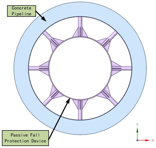
Figure 8.
Simplified schematic of the self-responsive anti-falling device.
3.1.2. Material Constitutive Parameter Calibration
Based on JMatPro multi-scale material modeling, the parameters are set as shown in Table 5:
Table 5.
Multiphase material constitutive parameters [37,38].
3.1.3. Contact Type Settings
The connection between the inclined shaft and the main structure through telescopic columns requires defining contact types to determine the interaction between their contact areas. ANSYS Workbench offers multiple contact types, and the following were configured based on actual conditions: Bonded Contact, No Separation, Frictionless, Frictional, and Rough Contact [40,41]. Since there is no relative friction between the inclined shaft and the main structure after connection via telescopic columns, Bonded Contact was selected.
3.1.4. Mesh Generation
Based on the operational parameters of the “Tianyue” TBM, this study utilized ICEM CFD 2022 R1 for professional meshing, with the workflow detailed as follows:
Geometric Model Preprocessing: The SolidWorks model was imported into ICEM via ANSYS Workbench 2022 R1.
Geometry Repair: Self-responsive gap stitching (tolerance = 0.1 mm). Duplicate surface removal. Topology defect correction using the Topo tool (topology repair tool).
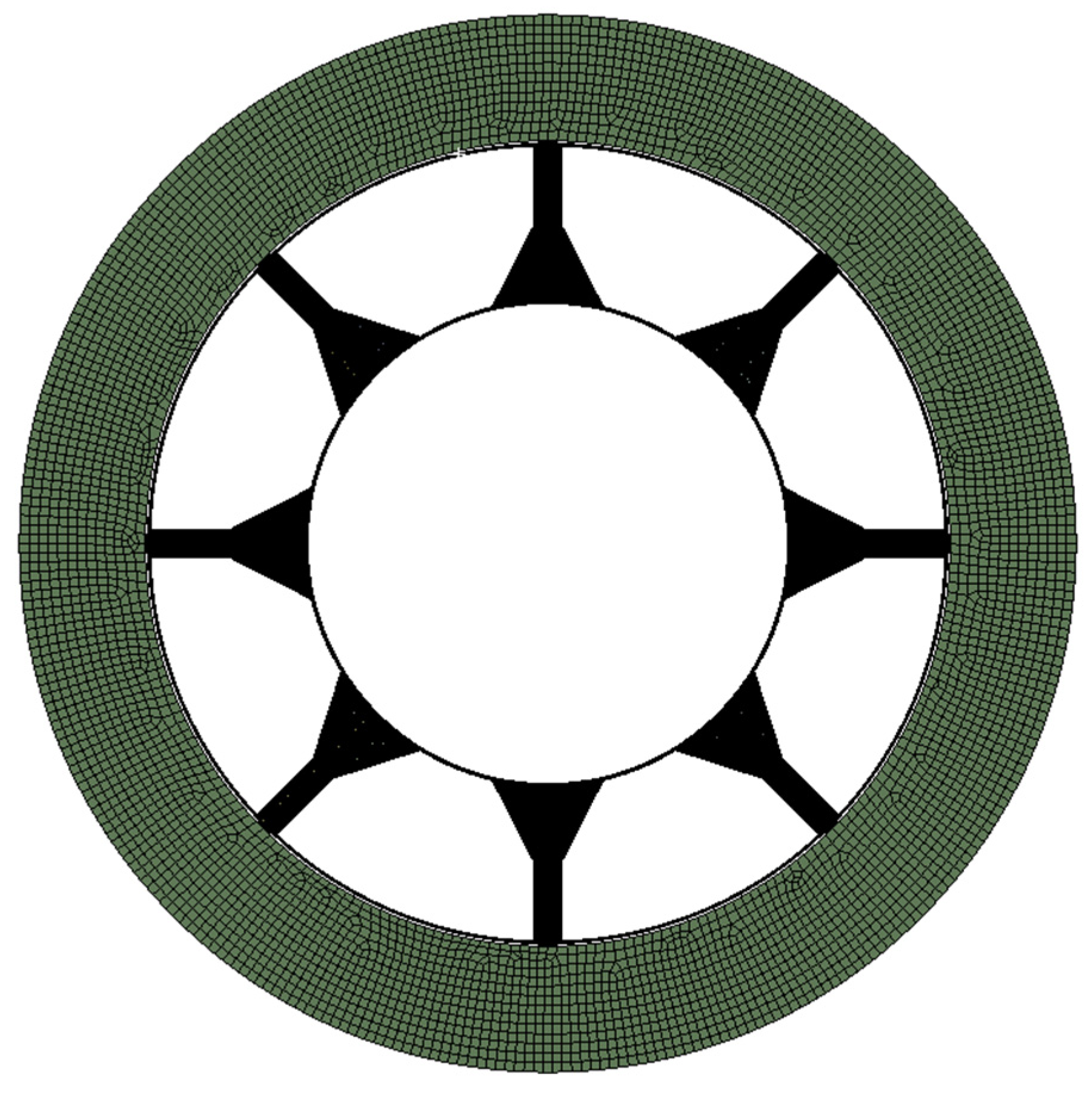
Grid sensitivity analysis was conducted to optimize discretization errors. The global base size was set to 50 mm for the main structural regions, with inflation layers (growth rate 1.2, 3 transition layers) configured in transition zones. A three-level adaptive refinement strategy was applied to stress concentration zones of the telescopic columns (cylindrical domain with radius r = 50 mm; see Figure 9), achieving a minimum element size of 2.1 mm. The final mesh quality complied with GB/T 33582-2017 [42] standards, featuring a distortion ratio < 0.65 and an average Jacobian > 0.82.
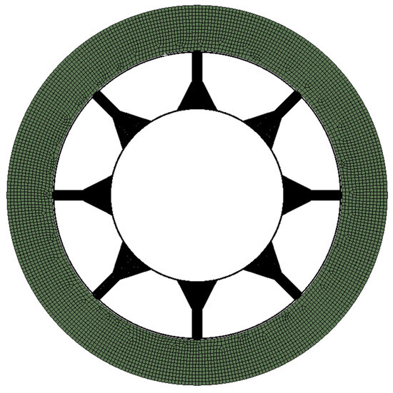
Figure 9.
Mesh effect.
3.1.5. Boundary Condition Implementation
Equivalent mechanical boundaries were established following Saint-Venant’s principle:
Loading Condition:
To account for impact amplification during free fall, the equivalent dynamic load was calculated as:
An equivalent axial load F = 1.332 × 10⁷ N was applied to the inner ring end face via uniform surface force loading.
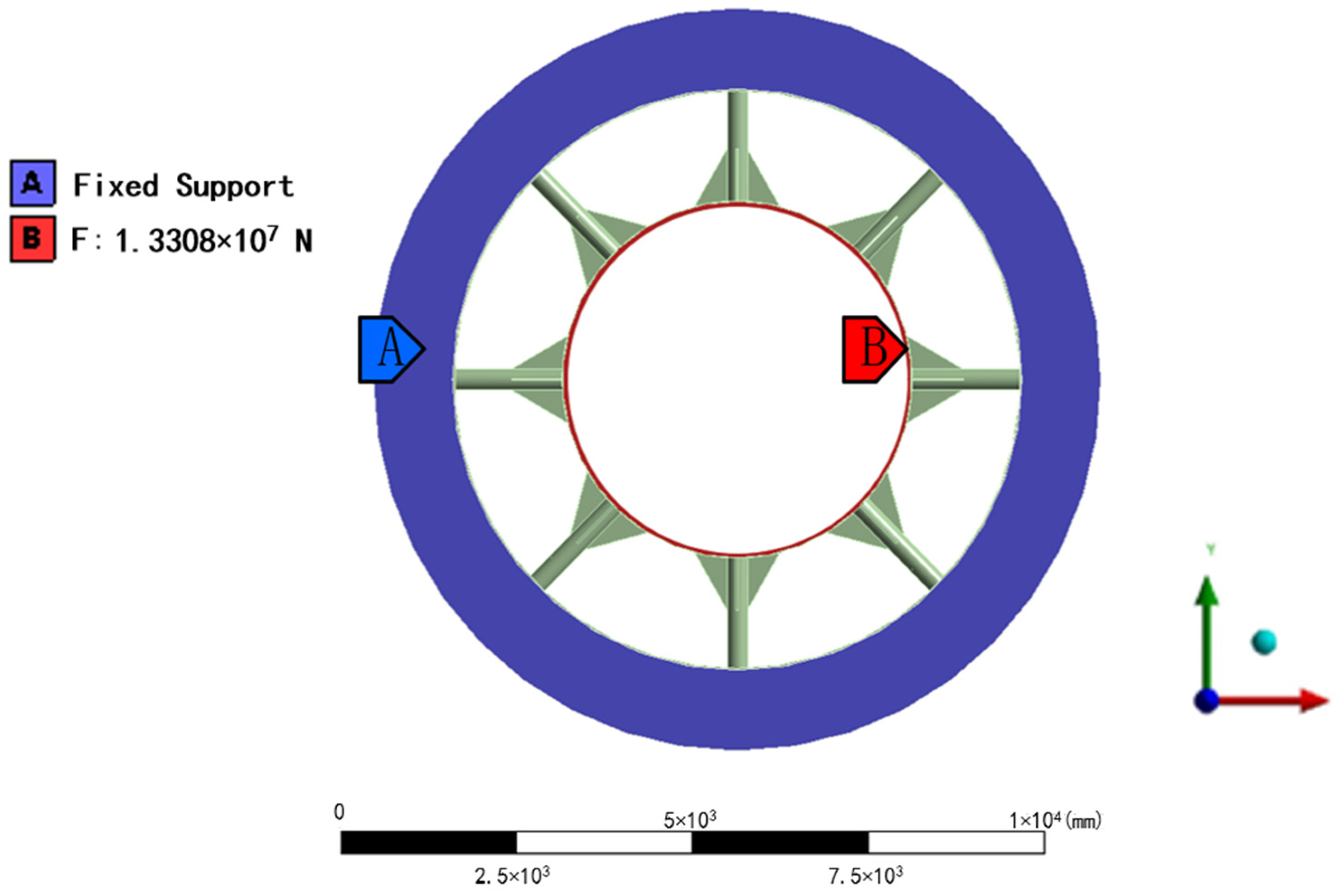
Constraint Condition: Full-degree-of-freedom constraints (UX = UY = UZ = 0) were imposed on the tunnel wall section to simulate the rigid support effect of the surrounding rock mass. The specific boundary conditions are configured. The specific settings are shown in Table 6, and the constraint/load positions are shown in Figure 10.
Table 6.
Boundary conditions setting.

Figure 10.
Load and constraint conditions: (A) Fixed support; (B) Applied loading.
3.1.6. Analysis of Simulation Results
- 1.
- Deformation Analysis
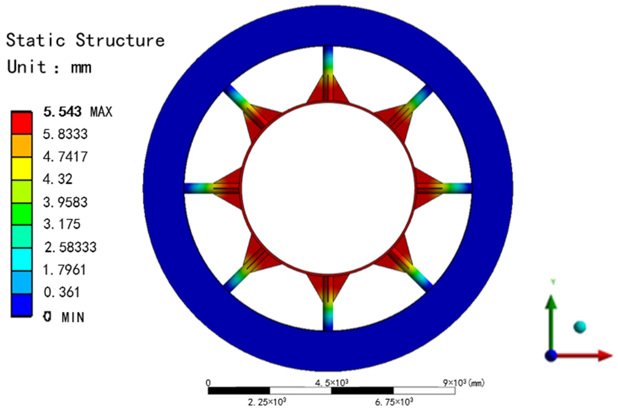
A static simulation was conducted using Workbench Mechanical, with total deformation as the key evaluation metric. As shown in Figure 11, the maximum displacement of the device is 5.543 mm, localized at the contact area between the tubular component and inner ring (coordinates: X = 225 ± 48 mm, Y = 675 ± 48 mm). This deformation magnitude complies with the ASME B30.26 [43] standard for allowable deformation thresholds in heavy engineering structures (<10 mm), demonstrating geometric integrity under a 900-ton equivalent load.

Figure 11.
Deformation contour of the self-responsive anti-falling device.
- 2.
- Stress Distribution and Strength Verification
The Von Mises yield criterion was applied for plastic material failure analysis, with stress distribution results shown in Figure 12:
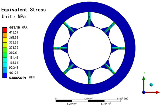
Figure 12.
Von Mises stress contour of the self-responsive anti-falling device.
Peak stress: 461.19 MPa at the device-shaft contact edge (X = 223 ± 3 mm, Y = 67 ± 3 mm).
Material strength: Quenched/tempered Q690D steel yield strength = 791 MPa [44].
Safety factor:
The results confirm the device meets ISO 12100 [45] safety requirements (n > 1.2) under design loads.
3.2. Dynamic Simulation Analysis
To analyze the operational availability and reliability of the TBM self-responsive device during working conditions, transient dynamic simulations were performed using the ANSYS Explicit Dynamics module. The stress distribution of moving components at different time steps was obtained to validate material usability and device performance.
3.2.1. Computational Model
A symmetric boundary condition was applied to simulate 1/8 of the typical structure (see Figure 5). A transient dynamic model of the anti-falling device was established in ANSYS Explicit Dynamics, as shown in Figure 13a (simplified 3D model) and Figure 13b (simplified cross-sectional view).

Figure 13.
Dynamic analysis model configuration: (a) Simplified 3D model for dynamic analysis; (b) Cross-sectional view of simplified model.
The model includes four functional components:
- Propellant Unit: TNT charge area modeled with ALE multi-material coupling algorithm [46]
- Telescopic Column: Q690D steel solid elements with Johnson-Cook plasticity model [47].
- Concrete Pipe: HJC constitutive model with layered mesh refinement (inner layer: 35 mm, outer layer: 100 mm).
- Constraint Boundaries: Fixed constraints on pipe exterior surfaces, bonded contacts at interfaces.
3.2.2. Material Calculation Parameters
Blast impact is a violent response to an explosion and mechanical impact, characterized by high frequency and high strain rate. The Johnson–Cook strength model can well simulate the behavior of materials at high strain rates. The Johnson–Cook strength model is expressed as [48,49]:
Table 7.
Johnson–Cook constitutive model parameters.
3.2.3. Propellant’s Equation of State
The propellant material chosen is TNT, using the explosive material parameter model provided by ANSYS. The equation of state for explosive detonation products adopts the JWL equation, which is used to describe high-energy explosives and detonation products, in the form of [52,53]:
The parameters of propellant materials are shown in Table 8 [54]:
Table 8.
Propellant material parameters.
The mesh configuration is shown in Figure 14:
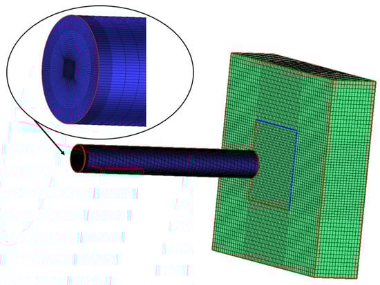
Figure 14.
Mesh configuration of anti-falling device.
This study employed ICEM CFD 2022 R1 for professional meshing, with the workflow detailed as follows:
Geometric Model Preprocessing: The SolidWorks model was imported into ICEM via ANSYS Workbench 2022 R1.
Geometry Repair: Self-responsive gap stitching (tolerance = 0.1 mm). Duplicate surface removal. Topology defect correction using the Topo tool (topology repair tool).
The computational mesh was strategically refined to balance accuracy and efficiency. Critical regions employed:
- ALE detonation zone (3.5 mm element size) for shockwave propagation
- Three-layer transitional mesh (expansion ratio 1.5) at fluid-structure interfaces
- Lagrangian concrete wall with inner layer (35 mm) and non-reflective outer boundary.
The dynamic stress propagation sequence during telescopic column penetration is illustrated in Figure 15:
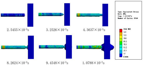
Figure 15.
Telescopic column penetration sequence.
The explicit dynamics simulation captured the full penetration chronology of the telescopic column through the concrete wall after propellant ignition. Key observations:
Energy Transfer Verification.
Peak pressure 159 MPa achieved at t = 8.2624 ms (Figure 15).
3.2.4. Material Performance Validation
Q690D steel components exhibited maximum von Mises stress 159 MPa at t = 8.2624 ms.
Dynamic Yield Strength Enhancement Effect:
Actual Safety Factor:
3.2.5. Penetration Performance
The comparative analysis of penetration performance verification indexes and results is shown in Table 9:
Table 9.
Comparative analysis of penetration performance verification metrics and results.
The experimental validation demonstrates that the self-responsive anti-falling device achieves dual compliance with critical safety thresholds:
Ultra-Fast Actuation: The 12 ms response time ensures timely intervention during TBM slippage events, outperforming conventional hydraulic systems (typical 150 ms latency).
Precision Penetration: With a mean depth of 500 mm, the propellant-driven mechanism provides deterministic energy transfer, generating sufficient shear resistance to stabilize 900-ton TBMs on 49° inclines.
3.2.6. Quantitative Analysis of Energy Dissipation Mechanisms
Figure 16 illustrates the energy conversion dynamics during TNT-driven penetration of a metal rod into concrete. In the initial phase (0–2.5 ms), explosive energy rapidly releases, with kinetic energy peaking at 15 MJ at 2.5 ms to propel the metal rod. Subsequently (2.5–10 ms), kinetic energy progressively converts to strain energy (representing concrete plastic deformation) and frictional dissipation (from interfacial sliding). The system reaches equilibrium beyond 12 ms, where the initial 20 MJ explosive energy completely transforms into 8 MJ strain energy and 12 MJ frictional energy, rigorously satisfying energy conservation. This transient process completes within 12 ms, characteristic of explosive loading, with 60% energy dissipation through friction and 40% stored as deformation energy-findings consistent with elastoplastic theory. Energy balance analysis confirmed model reliability [55,56]:

Figure 16.
Energy conservation verification.
Residual energy ΔE = 3.7% demonstrates excellent conservation characteristics.
4. Conclusions and Outlook
4.1. Conclusions
This study presents a groundbreaking safety solution for steeply inclined tunnel boring machine (TBM) operations by developing an innovative propellant-driven self-responsive anti-falling system. Addressing the critical challenges of conventional anti-falling devices in large-inclination (up to 49°) shaft construction, our research achieves three transformative technological breakthroughs that significantly enhance operational safety and reliability. The system’s intelligent sensing module employs an advanced multi-parameter fusion algorithm (RMS + STE + ZCR) integrated with triple-redundant MEMS accelerometers (±50 g range, 1 kHz bandwidth) and Butterworth filtering (100 Hz cutoff frequency), enabling an industry-leading 12 ms response time—12.5 times faster than traditional hydraulic systems—while maintaining exceptional reliability, with false alarm rates below 0.3%, compliant with ISO 13849-1 SIL3 safety standards. Structural analysis demonstrates that the Q690D steel load-bearing components exhibit outstanding performance, with a maximum von Mises stress of 461.19 MPa and safety factor of 1.71 under 900-ton equivalent loading conditions, exceeding the minimum 1.5 safety factor required by ASME BTH-1-2023 [57] for impact loading scenarios. The TNT propellant system ensures consistent 500 mm penetration depth in concrete linings. These technological breakthroughs collectively provide unprecedented safety assurance for steep-inclination tunnel construction projects, particularly in challenging applications such as pumped storage power stations.
4.2. Outlook
Building on these findings, future research should pursue three key directions to expand the application scope of anti-falling devices. Firstly, developing advanced materials like titanium alloys and functionally graded composites could potentially extend the operational slope limit beyond the current 49° threshold while maintaining safety factors above 1.5. Secondly, a comprehensive multiphysics model integrating propellant combustion, frictional heating, and rock damage using SPH-FEM hybrid algorithms would improve penetration prediction accuracy for steeper inclinations. Third, an advanced testing platform with ±100 g acceleration simulation capability (to verify structural integrity under extreme transients) and adjustable rock targets (30–120 MPa) is needed to validate reliability through 108 cycle endurance tests across various slope conditions. Implementation also requires intelligent monitoring systems combining fiber optic strain sensors and acoustic emission diagnostics to enable predictive maintenance. Further material characterization under extreme environments (−40 °C to >10 MPa pressure) through low-temperature impact and corrosion tests will be essential for expanding both slope range and operational boundaries. Addressing these challenges will advance next-generation TBM safety systems for increasingly steep and complex geological conditions.
Author Contributions
Conceptualization, H.P. and B.L.; methodology, L.S., C.X. and C.Y.; investigation, H.P., C.Y. and W.Y.; writing—original draft preparation, H.P. and. C.Y.; writing—review and editing, H.P., L.J. and W.Y.; All authors have read and agreed to the published version of the manuscript.
Funding
This study was supported by North China University of Water Resources and Electric Power Graduate Student Innovation Ability Enhancement Project (NCWUYC-202416070, NCWUYC-202416068), Postgraduate Education Reform and Quality Improvement Project of Henan Province (YJS2025AL08), Graduate Education Reform Project of Henan Province (2023SJGLX122Y), Major Scientific and Technological Special Projects of Henan Province (231100220700), and North China University of Water Resources and Electric Power Graduate Education Reform and Quality Enhancement Project (NCWUSZKC202307).
Data Availability Statement
Data will be made available on request.
Conflicts of Interest
Author Lianhui Jia was employed by the company China Railway Engineering Equipment Group Co., Ltd. The remaining authors declare that the research was conducted in the absence of any commercial or financial relationships that could be construed as a potential conflict of interest.
References
- Jing, Z.; Wang, Y.; Chang, J.; Wang, X. Construction of pumped storage power stations among cascade reservoirs to support the high-quality power supply of the hydro-wind-photovoltaic power generation system. Energy Convers. Manag. 2025, 323, 119239. [Google Scholar] [CrossRef]
- Xiang, C.; Xu, X.; Zhang, S. Current situation of small and medium-sized pumped storage power stations in Zhejiang Province. J. Energy Storage 2024, 78, 110070. [Google Scholar] [CrossRef]
- Xu, L.; Liu, Z.; Zheng, S. Exploration on Planning and Development of Pumped Storage Power Stations in China. In Proceedings of the IOP Conference Series: Earth and Environmental Science; IOP Publishing: Bristol, UK, 2021; Volume 781, p. 042058. [Google Scholar]
- Khetwal, A.; Rostami, J.; Nelson, P. Investigating the impact of TBM downtimes on utilization factor based on sensitivity analysis. Tunn. Undergr. Space Technol. 2020, 106, 103586. [Google Scholar] [CrossRef]
- Shi, W.; Ge, W. Challenging Issues in the Construction and Engineering of the Deeply Buried Long Tunnel Complex of the Jinping II Hydropower Station. J. Rock. Mech. Eng. 2010, 29, 11. [Google Scholar]
- News Commentary: Civil Engineering. Tunnel Construction for Hokkaido Shinkansen Suspended due to Rock Lumps; Removal Takes More Than 18 Months. Available online: https://xtech.nikkei.com/atcl/nxt/column/18/00142/01217/ (accessed on 18 February 2022).
- Zhou, J.; Tao, L. Anti-Slip Self-Locking Propulsion Structure for Large Slope Inclined Shaft Tunnel Boring Machine. CN107366543B, 23 April 2019. [Google Scholar]
- Shi, W.; Yang, J. Anti-Skid Device and System for Trailer of Tunnel Boring Machine. CN213138790U, 7 May 2021. [Google Scholar]
- He, Q.; Ni, X. Multifunctional Anti-Skid Stopper Frame for Shield Machine. CN207660642U, 27 July 2018. [Google Scholar]
- Xie, X. Small-diameter soil-pressure balance shield large slope anti-skidding technology. Sichuan Build. Mater. 2022, 9, 048. [Google Scholar]
- Ma, B. Research on Damage Mechanism and Control Technology of Jointed Surrounding Rock Under Vibration Disturbance of Coal Mine TBM Excavation. Ph.D. Thesis, China University of Mining and Technology, Xuzhou, China, 2024. [Google Scholar]
- Sun, W.; Ding, X.; Wei, J.; Wang, X.; Zhang, A. Hierarchical modeling method and dynamic characteristics of cutter head driving system in tunneling boring machine. Tunn. Undergr. Space Technol. 2016, 52, 99–110. [Google Scholar]
- Deng, K.; Ding, Y.; Zeng, L.; Yin, Z. Force Transmission Characteristics for Thrust System in Rectangular Shield Machine. IEEE Access 2019, 7, 177804–177812. [Google Scholar]
- Li, Z.; Chen, Y.; Sun, W.; Jiang, P.; Pan, J.; Guan, Z. Study on self-loosening mechanism of bolted joint under rotational vibration. Tribol. Int. 2021, 161, 107074. [Google Scholar]
- Deng, L.; Luo, B.; Zhang, K.; Cheng, H.; Long, K.; Liang, B. Failure law of hydraulic pipe joints sealing performance under vibration loads. Eng. Fail. Anal. 2024, 166, 108906. [Google Scholar]
- Zhang, W.; Jiang, S.; Li, X.; Wang, Z. An approach to structural reliability evaluation under fatigue degradation and shocks. Mech. Syst. Signal Process. 2018, 113, 65–76. [Google Scholar]
- Corporate Announcement Search Results. About the Construction of the Yokohama Loop South Katsudai Tunnel. Available online: https://www.e-nexco.co.jp/zh-CHS/pressroom/kanto/2022/0202/00010844.html (accessed on 6 August 2021).
- Nasybullov, T. Connections between properties of the additive and the multiplicative groups of a two-sided skew brace. J. Algebra 2019, 540, 156–167. [Google Scholar]
- Gao, C.; Zhou, Z.; Li, Z.; Li, L. Peridynamics simulation of surrounding rock damage characteristics during tunnel excavation. Tunn. Undergr. Space Technol. 2020, 97, 886–7798. [Google Scholar] [CrossRef]
- Wu, Z.; Gu, F.L. World’s First Variable-Diameter Inclined Shaft TBM Launched in Changsha. Mod. Tunn. Technol. 2023, 60, 193. [Google Scholar]
- ISO 13849-1:2023; Safety of Machinery-Safety-Related Parts of Control Systems Part 1: General Principles for Design. European Committee for Standardization: Brussels, Belgium, 2023.
- Liao, J.; Zhu, X.; Yao, B. Dynamic modeling of gripper type hard rock tunnel boring machine. Tunn. Undergr. Space Technol. 2018, 71, 166–179. [Google Scholar] [CrossRef]
- Chen, G.; Yang, Y.; Huang, T. Vibration analysis of open TBM gripping-thrusting-regripping mechanism. Mech. Mach. Theory 2019, 134, 95–116. [Google Scholar] [CrossRef]
- Zou, X.; Zheng, H.; Mi, Y. Performance evaluation of hard rock TBMs considering operational and rock conditions. Shock Vib. 2018, 1, 17. [Google Scholar] [CrossRef]
- Qi, J.X.; Hai, D.Y. Coupling relationship between loads on cutterhead of tunnel boring machine and contact stiffness of gripper shoes and rocks. J. Shanghai Jiaotong Univ. 2015, 49, 1269–1275. [Google Scholar]
- Hao, P.; Yu, H.; Zhao, Y. Normal stiffness of tunnel surface contacting with thrusting boots of TBM with various surface characteristics. J. Shanghai Jiaotong Univ. 2014, 48, 827–832. [Google Scholar]
- Shao, C.; Liao, J.; Liu, Z. Indirect adaptive robust trajectory tracking control of hard rock TBM with load variation of tunneling face. Chin. J. Mech. Eng. 2019, 32, 34. [Google Scholar] [CrossRef]
- Unterlass, P.; Erharter, G.; Marcher, T. Identifying Rock Loads on TBM Shields During Standstills (Non-Advance-Periods). Geotech. Geol. Eng. 2023, 41, 75–89. [Google Scholar] [CrossRef]
- Shaterpour-Mamaghani, A.; Deniz, T. Double shield TBM performance analysis in difficult ground conditions: A case study in the Gerede water tunnel, Turkey. Bull. Eng. Geol. Environ. 2015, 75, 251–262. [Google Scholar] [CrossRef]
- Shi, L.; Zhou, H.; Song, M.; Lu, J.; Liu, Z. Geomechanical model test for analysis of surrounding rock behaviours in composite strata. J. Rock. Mech. Geotech. Eng. 2021, 13, 774–786. [Google Scholar]
- Pourhashemi, S.M.; Ahangari, K.; Hassanpour, J.; Eftekhari, S.M. Evaluating the influence of engineering geological parameters on TBM performance during grinding process in limestone strata. Bull. Eng. Geol. Environ. 2021, 80, 3023–3040. [Google Scholar]
- Shi, H.; Yang, H. Shield tunneling machine key technology and simulation test bench status and outlook. J. Zhejiang Univ. (Eng. Ed.) 2023, 47, 5. [Google Scholar]
- Kang, X.; Xie, X.; Zeng, K. A New Self-Sensing Fiber Optic Anchor to Monitor Bolt Axial Force and Identify Loose Zones in the Surrounding Rock of Open TBM Tunnels. Sensors 2024, 24, 6709. [Google Scholar] [CrossRef] [PubMed]
- Monsberger, C.M.; Lienhart, W.; Kluckner, A. Continuous Strain Measurements in a Shotcrete Tunnel Lining Using Distributed Fibre Optic Sensing. In Proceedings of the 9th European Workshop on Structural Health Monitoring, Manchester, UK, 10–13 July 2018. [Google Scholar]
- Monsberger, C.M.; Lienhart, W. Distributed Fiber Optic Shape Sensing Along Shotcrete Tunnel Linings: Methodology, Field Applications, and Monitoring Results. J. Civ. Struct. Health Monit. 2021, 11, 337–350. [Google Scholar] [CrossRef]
- World’s First Large-Slope and Vertical Curve Steering Variable-Diameter Inclined Shaft TBM “Tianyue” Successfully Completed. Jiangxi Build. Mater. 2024, 11, 196.
- Wang, M.; Lou, G.; Li, G.; Jiang, B. Mechanical properties and constitutive model of Q690 steel in the fire-cooling stage. Fire Saf. J. 2023, 141, 103994. [Google Scholar]
- Zhao, W.; Gao, H.; Chen, W.; Liu, J.; Peng, W.; Zhou, S. Experimental study on similar materials for tunnel lining concrete in geomechanical model tests. Eng. Fail. Anal. 2023, 152, 107456. [Google Scholar] [CrossRef]
- Wang, M.; Wu, J.; Fan, H.; Zhang, Z.; Wu, H. Extraction of the Anisotropic Plasticity of Metal Materials by Using Inverse Analysis and Dual Indentation Tests. Materials 2018, 11, 12. [Google Scholar] [CrossRef]
- Tian, C. Study on Impact Resistance of Composite Sandwich Structures in Low-Temperature Environments. Ph.D. Thesis, Academy of Military Sciences, Beijing, China, 2024. [Google Scholar]
- Liu, W. Experimental and Simulation Study on Impact Damage Models of Aluminum Alloy Thin-Walled Structures. Ph.D. Thesis, Beijing Jiaotong University, Beijing, China, 2023. [Google Scholar]
- GB/T 33582-2017; General Principles of Structural Finite Element Analysis for Mechanical Products. China National Institute of Standardization: Beijing, China, 2017.
- ASME B30.26-2015; Rigging Hardware Safety Standard for Cableways, Cranes, Derricks, Hoists, Hooks, Jacks, and Slings. The American Society of Mechanical Engineers: New York, NY, USA, 2015.
- Zong, L.; Liu, H.; Si, Q.; Chung, K. Pre-fatigue damage on the mechanical properties of Q690D steel. Fatigue Fract. Eng. Mater. Struct. 2023, 46, 3306–3320. [Google Scholar] [CrossRef]
- ISO 12100: 2010; Safety of Machinery-General Principles for Design-Risk Assessment and Risk Reduction. European Committee for Standardization: Brussels, Belgium, 2010.
- Dong, Q. Numerical Study on Dynamic Response of CFRP-Strengthened Reinforced Concrete Slabs Under Blast Loading. Ph.D. Thesis, Xiangtan University, Xiangtan, China, 2018. [Google Scholar]
- Mareau, C. A thermodynamically consistent formulation of the Johnson–Cook model. Mech. Mater. 2020, 143, 103340. [Google Scholar]
- Choi, Y.; Kim, S.; Kwon, S.L.; Choi, H.; Yun, G.J. Multi-stage Johnson–Cook Model for Collision Analysis: Impact Experiments and Simulations. Int. J. Aeronaut. Space Sci. 2025, 26, 599–614. [Google Scholar] [CrossRef]
- Shen, Y.; Lin, L.; Tang, P.; Xu, T. Impact Dynamic Response of Spherical Net Shells: Finite Element-Based Computational Analysis Investigating the Influence of Dynamic Constitutive Models. Buildings 2023, 13, 1849. [Google Scholar] [CrossRef]
- Wei, X.; Chen, S.; Li, G.Q. Strain rate-temperature effects and constitutive models for Q690D QT steel. J. Constr. Steel Res. 2024, 218, 108728. [Google Scholar]
- Li, C. Failure Mechanism and Explosion Prevention Method of Column Surface Mesh Shell Structure Under Internal Explosion. Ph.D. Thesis, Huaqiao University, Xiamen, China, 2017. [Google Scholar]
- Bornstein, H.; Kuznetsov, V.; Lu, J.P.; Stojko, S.; Freundt, J. Characterisation and validation of the JWL equation of state parameters for PE4. Int. J. Impact Eng. 2022, 164, 104190. [Google Scholar]
- Mortensen, C.; Souers, P.C. Optimizing Code Calibration of the JWL Explosive Equation-of-State to the Cylinder Test. Propellants Explos. Pyrotech. 2017, 42, 616–622. [Google Scholar] [CrossRef]
- Lee, E.; Finger, M.; Collins, W. JWL Equation of State Coefficients for High Explosives; UCID-16189; Lawrence Livermore National Laboratory: Lawrence, CA, USA, 1973. [Google Scholar]
- Belytschko, T.; Liu, W.K.; Moran, B.; Elkhodary, K. Nonlinear Finite Elements for Continua and Structures, 2nd ed.; Wiley: Chichester, UK, 2014; pp. 628–631. [Google Scholar]
- Dobratz, B.M. LLNL Explosives Handbook: Properties of Chemical Explosives and Explosive Simulants; UCRL-52997; Lawrence Livermore National Laboratory: Livermore, CA, USA, 1985; Chapter 6. [Google Scholar]
- ASME BTH-1-2023; Design of Below-the-Hook Lifting Devices. The American Society of Mechanical Engineers: New York, NY, USA, 2023.


Disclaimer/Publisher’s Note: The statements, opinions and data contained in all publications are solely those of the individual author(s) and contributor(s) and not of MDPI and/or the editor(s). MDPI and/or the editor(s) disclaim responsibility for any injury to people or property resulting from any ideas, methods, instructions or products referred to in the content. |
© 2025 by the authors. Licensee MDPI, Basel, Switzerland. This article is an open access article distributed under the terms and conditions of the Creative Commons Attribution (CC BY) license (https://creativecommons.org/licenses/by/4.0/).