1. Introduction
Friction stir welding (FSW) has demonstrated its capability to join high-strength aluminum alloys, which are highly desirable for the aerospace industry, particularly the AA2024 alloy. Welds subjected to static and cyclic loads often represent the weakest points in a structure, determining the overall mechanical properties of components in service. As is well known, the gradient thermo-mechanical conditions inherent in the FSW process create significant variations along the weld in terms of microstructure, residual stress fields, and crystallographic texture, ultimately influencing fracture location and mechanical performance. As a result, a large and growing body of literature has extensively examined the factors contributing to the premature failure of friction stir-welded 2000-series aluminum alloys. Provided that the weldment is sound, these factors are as follows:
Since Al-Cu-(Mg) alloys (2000 series) belong to the category of heat-treatable aluminum alloys, precipitation phenomena have a profound influence on the mechanical properties of FSW joints. Previous research findings have shown that softening due to the overaging of precipitates in the thermo-mechanically affected zone (TMAZ) or the heat-affected zone (HAZ), depending on the temperature distribution, often leads to fracture, Shukla and Baeslack [
1], Zhang et al. [
2], Morita and Yamanaka [
3] and Genevois et al. [
4].
The oxide layer captured from the sheet surface, fractured, and redistributed within the stir zone (SZ) can form a defect known as a remnant oxide line (ROL), joint line remnant, zigzag line, or lazy S. Studies investigating the relationship between ROL characteristics and the mechanical integrity of FSW joints in Al-Cu-(Mg) alloys indicate that oxide films can initiate failure due to their continuous, concentrated distribution and/or insufficient fragmentation. Consequently, they degrade tensile strength, elongation, and fatigue life, Zhou et al. [
5], Chen et al. [
6] and Niu et al. [
7]. Even when the ROL does not affect joint performance in the as-welded condition, it deteriorates the mechanical properties of the heat-treated joint, Liu et al. [
8]. It is worth noting that a kissing bond, which is sometimes mistakenly attributed to ROL in certain sources, has been found to deteriorate the fatigue life of 2024 friction stir welds once its critical size at the weld root is reached, Růžek et al. [
9].
The FSW process introduces residual stresses that are nonuniformly distributed across different weld regions, Laska et al. [
10]. It has been reported that although low tensile residual stresses are induced in the FSW welds of heat-treatable aluminum alloys, they can still promote fatigue crack initiation and growth, Bussu and Irving [
11], John et al. [
12] and Altenkirch et al. [
13]. Interestingly, Bussu and Irving [
11] primarily attributed crack growth behavior to residual stresses rather than grain structure or hardness, i.e., the precipitation state.
Constituent particles, also referred to as intermetallic particles, present in the base material (BM) are severely fragmented and re-distributed in the SZ and TMAZ. These changes have been reported to affect hardness along the weld, as by Salem [
14] and Sutton et al. [
15], as well as failure location and the corresponding tensile and fatigue properties of 2000-series alloys, Zhang et al. [
2], Sutton et al. [
15], Mishra and Mahoney [
16] and Booth et al. [
17]. A series of studies conducted by Sutton and Yang on friction stir welded 2024-T3 alloy, Yang et al. [
18], Sutton et al. [
19,
20], established that the discontinuous distribution of constituent particles within the SZ initiated the fracture. This occurred because cracks tended to propagate along bands of higher particle density due to stresses at the particle–matrix boundary. The agglomeration of particles has been associated with the “onion ring” structure both in these studies and elsewhere, Booth et al. [
17], Norman et al. [
21], Aydin et al. [
22], Chen et al. [
23] and Sutton et al. [
24]. It has been shown that variations in the density of fragmented particles within the “onion ring” layers contribute to failure along them. Furthermore, Zhang et al. [
2] reported that linear segregation of constituent particles at the SZ/TMAZ interface or within the SZ was critical, causing the fracture location to shift away from the region of lowest hardness.
Recently, the Taylor factor has been gaining more attention as an indicator for predicting fracture locations based on crystallographic orientations across FSW joints in aluminum alloys. Fonda et al. [
25] reported that the Taylor factor did not correlate with the tensile failure behavior of 2519 joints. In contrast, several studies suggest that weld regions with the smallest Taylor factor are more prone to crack initiation and propagation, ultimately leading to joint rupture, Tayon et al. [
26], Xu et al. [
27] and Tao et al. [
28]. In some cases, the failure of welded heat-treatable aluminum alloys even shifted from the TMAZ/HAZ region, where fracture typically occurs due to precipitate overaging, to the SZ, indicating that the Taylor factor can have a greater influence than precipitation phenomena, Xu et al. [
27] and Tao et al. [
28]. Studies from Sato [
29] and Sato and Kokawa [
30] emphasized that the Taylor factor determines fracture location only when a homogeneous hardness profile exists across the weld. However, in cases where hardness varies, the region of lowest hardness remains the weakest point of the joint.
These studies clearly indicate that the fracture behavior of FSW joints in heat-treatable aluminum alloys is complex, as multiple factors contribute to failure. Understanding the relationship between the macro- and microstructural characteristics of the weld and its mechanical performance is essential for effective control. It should be noted that the precipitation phenomena of the studied AA2024-T351 alloy were previously reported in Ref. Morozova et al. [
31]. The current research focuses on investigating other factors to assess their influence on tensile and fatigue properties and to evaluate their role in the overall mechanical performance of the joints.
2. Materials and Experimental Procedure
The aluminum alloy AA2024-T351 used in this study had a nominal chemical composition of Al–4.94Cu–1.28Mg–0.41Mn–0.08Fe–0.11Si–0.07Ti–0.11Sn (wt.%).
Sheets with dimensions of 110 × 400 × 1.9 (W × L × T, in mm) were butt-welded using both conventional friction stir welding (FSW) and impulse friction stir welding (IFSW) techniques, utilizing a five-axis FSW machine, Matec 40P (Matec GmbH, Köngen, Germany). This machine is equipped with a direct axial force control system, consisting of an orbital control force spindle and a coaxial sensor. The sensor measures the axial force during welding. Simultaneously, the axial electrical actuator adjusts the tool position to maintain the axial force according to the previously set value. Therefore, it is possible to monitor, control, and record the actual force during welding.
To implement impulse-based processing, the machine was modified by adding an additional Z2 axis equipped with an electric drive. In IFSW, the principle of impulse application is based on the concept that the constant force used in conventional FSW corresponds to the average force of the impulses, as demonstrated in Ref. Morozova et al. [
31]. The axial position of the tool is controlled to maintain the pre-defined downforce. The system allows for programmable control of impulse parameters, including their form, force, and frequency. In the present study, a sinusoidal waveform was used for the impulses. This resulted in a periodic variation in the contact area between the tool and the workpiece.
The tool used for both FSW and IFSW was made of H13 tool steel and featured a smooth concave shoulder with a diameter of 15 mm and a smooth cylindrical probe with a diameter of 4 mm and a length of 1.8 mm. The tilt angle was set to 2°. The applied welding parameters are summarized in
Table 1.
It is essential to note that the welds were tested after six months of natural aging (NA) so that all precipitation reactions were completed. Samples for optical microscopy were cut using a slow-speed diamond saw under water cooling, cold-mounted in acrylic resin, and polished to a 0.05 μm finish. For etching, Beraha II reagent was applied by immersing the polished specimens for 5 s.
Polished, unetched specimens were examined using a scanning electron microscope (SEM), specifically the TESCAN MIRA II (Brno, Czech Republic), equipped with an INCA Oxford detector for energy-dispersive X-ray spectroscopy (EDS) to characterize the chemical composition of constituent particles. The particle size was automatically estimated with a detection limit of 0.5 μm. The SEM was also used to examine fracture surfaces after tensile and fatigue tests, with specimens sonicated for 30 s before observation.
Electron backscatter diffraction (EBSD) samples were mounted in epoxy resin, mirror-polished, and then subjected to surface preparation using a VibroMet 2 vibratory polisher (Buehler, Uzwil, Switzerland) in a Leco solution at room temperature for 60 min. EBSD analysis was performed using an EDAX EBSD system (AMETEK Materials Analysis Division, Mahwah, NJ, USA) with a step size of 0.2 µm.
The grain-specific Taylor factor was computed according to the EBSD results using a family of active slip systems for FCC structures ({111}<110>) and a deformation gradient for uniaxial tension in the transverse direction, i.e., parallel to the tensile and fatigue load:
The Vickers microhardness was measured along the centerline of the transverse weld section using a load of 0.980 N (HV 0.1) for 10 s.
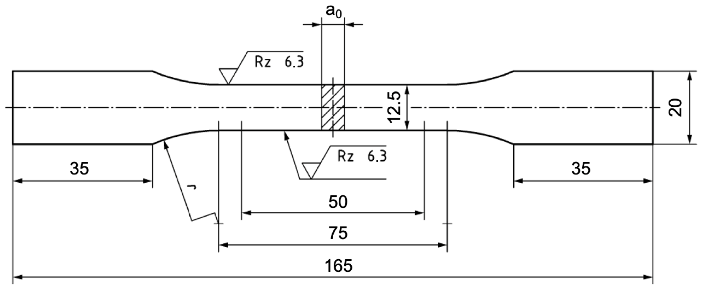
Tensile testing was conducted on flat specimens extracted by laser cutting, ensuring that the center of the gauge section corresponded to the welding line and that the loading direction was perpendicular to the welding direction. The tensile specimen geometry is shown in
Figure 1. Tensile tests were performed at room temperature with a crosshead speed of 10 mm/min. Each test was carried out until specimen rupture. The ultimate tensile strength, yield strength, and elongation of the joint were determined based on tests conducted on ten tensile specimens.
Fatigue testing was conducted to determine the number of cycles to failure based on the applied load. The fatigue specimen geometry was identical to that of the tensile specimens (
Figure 1). The specimen surfaces were not mechanically machined before testing to account for the influence of surface defects. Fatigue tests were performed at a loading frequency of 10 Hz and a stress ratio of R = 0.1 in laboratory air. The fatigue test target was set to 1 × 10
7 cycles.
3. Results
3.1. Microhardness Distribution
Figure 2 presents the microhardness profiles across the studied FSW and IFSW joints. The microhardness of the base material (BM) was 145 ± 5 HV
0.1. The hardness in the SZ increased above the BM level, reaching approximately 150 HV
0.1. The hardness values were similar across all welds.
The minimum hardness of 130 HV was observed in the FSW joint on both the advancing side (AS) and the retreating side (RS). In the IFSW joints, however, the hardness minimum was higher on both sides and shifted closer to the SZ compared to FSW. Specifically, in the IFSW 2 kN 2 Hz joint, the maximum softening occurred at a distance of ~5 mm from the weld center, whereas in the FSW joint, it was ~6.5 mm. This indicates that IFSW resulted in a narrower temperature field, leading to a more localized softened region compared to FSW.
A distinctive feature of IFSW was observed in the HAZ adjacent to the BM. The IFSW joints exhibited a significant hardness increase, with a maximum value of 162 HV for the 2 kN 2 Hz weld at a distance of ~8.5 mm from the weld center. As the impulse force increased, the maximum hardness decreased. This behavior is explained by the precipitation changes and reported in Ref. Morozova et al. [
31].
3.2. Tensile Properties
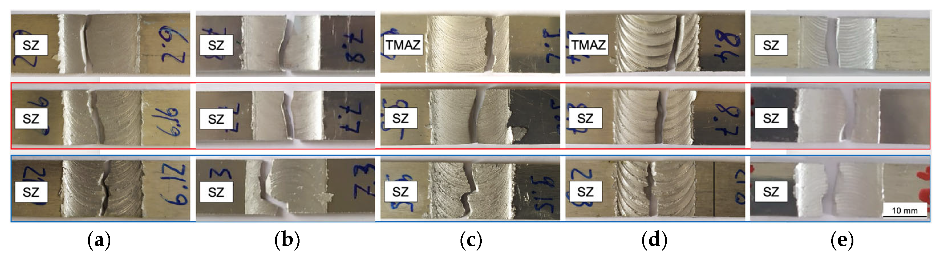
Table 2 provides the tensile characteristics of the studied joints in connection to the fracture location. Furthermore,
Figure 3 shows a closed inspection of the fractured cross-sections of the etched specimens. The AS and RS are located on the right and left side of all macrographs, respectively. The zones where the rupture of the tensile specimen took place are denoted in the pictures.
All FSW welds fractured in the SZ, close to the SZ/TMAZ boundary on the AS. Note that this location did not correspond to the hardness minimum.
The samples from the IFSW 2 kN 2 Hz and IFSW 6 kN 2 Hz joints broke up either in the SZ or in the TMAZ (70% vs. 30% of the specimens, respectively). The fracture line in the TMAZ was typically inclined at 45°. Since this location coincided with the hardness minimum, it can be concluded that it was caused by the precipitation overaging. Interestingly, the TMAZ was the weakest region of the IFSW 6 kN 2 Hz joint even though the crack propagated from the weld bottom in the transition region between the SZ and TMAZ on the AS (designated by the red arrow in
Figure 3). The material in the TMAZ possessed higher mechanical properties, especially the elongation values, compared to the material fractured in the SZ.
All specimens welded at 2 kN 6 Hz fractured in the SZ, having a zigzag fracture line. The 6 kN 6 Hz specimens failed in the transition region at the AS. Here it is important to note that the mechanical values varied in a wide range, depending on the specimen. For instance, the elongation values varied between 3 and 7% despite the fact that the fracture occurred in one zone.
A significant enhancement in the tensile strength (over 20%) was achieved by IFSW compared to FSW. What is striking about the data in the table is that the yield strength was almost the same for all welds, although it was higher in the TMAZ. Therefore, shifting the fracture location from the SZ to the TMAZ with IFSW marginally increased the overall yield strength of the joints. The elongation in both the SZ and the TMAZ of impulse welds was significantly higher than in the SZ of the conventional FSW weld. When comparing the elongation in the SZ between FSW and IFSW welds, the following trend can be distinguished. At a lower impulse frequency, the elongation increased by a factor of three compared with the FSW weld, and at a higher impulse frequency of 6 Hz, it reached a fivefold increase.
3.3. Fatigue Test
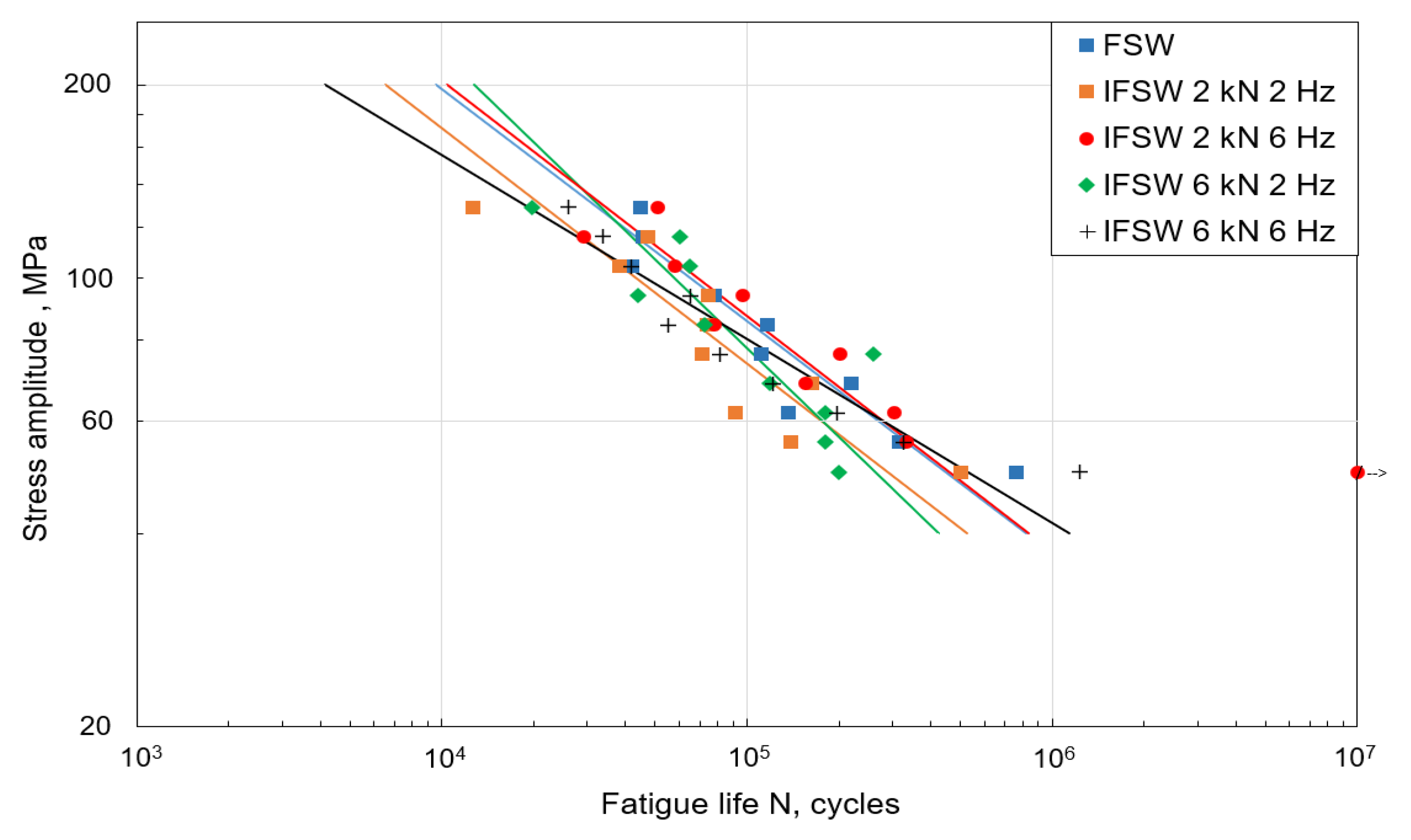
Figure 4 summarizes the results of the fatigue test for the studied welds. The fatigue limit is defined as the fatigue strength at N = 10
7 cycles. Overall, all values of the fatigue life were tightly packed at all stress amplitudes. The IFSW 2 kN 6 Hz joint demonstrated better results among all joints, so the fatigue limit was not reached at the lowest stress amplitude. The stress amplitude values of other impulse welds were slightly lower compared to the FSW welds; however, an improvement in fatigue life was recognized for a higher impulse frequency of 6 Hz (black and red lines in
Figure 4) at lower stress amplitudes. For instance, the number of cycles at a stress amplitude of 49.9 MPa increased from ~7 × 10
5 cycles for FSW to ~1.2 × 10
6 cycles for IFSW 6 kN 6 Hz.
Most of the FSW and IFSW specimens ruptured within the SZ. Only a small number of IFSW specimens failed on the SZ/TMAZ interface (~10% for IFSW 2 kN 6 Hz, 6 kN 2 Hz, and 6 kN 6 Hz).
Figure 5 exhibits a top view of the FSW and IFSW weld surfaces showing the crack path propagating through different weld regions. The failure line appeared in various forms, e.g., smooth (marked with a red frame in
Figure 5) or ragged with pronounced deflections (marked with a blue frame in
Figure 5). The propagation of a deflected crack is indicative of the influence of surface defects such as contiguous lamellas or the defects identified in the SZ (
Figure 5). The specimens fractured in the SZ were used for analyzing the exact reason for fatigue failure. The detailed observation of the crack initiation was carried out on the fracture surfaces by SEM, and the corresponding results are described in the corresponding section. In addition, crystallographic texture was evaluated as one of the factors affecting the properties of the FSW joints.
3.4. Microstructural Studies
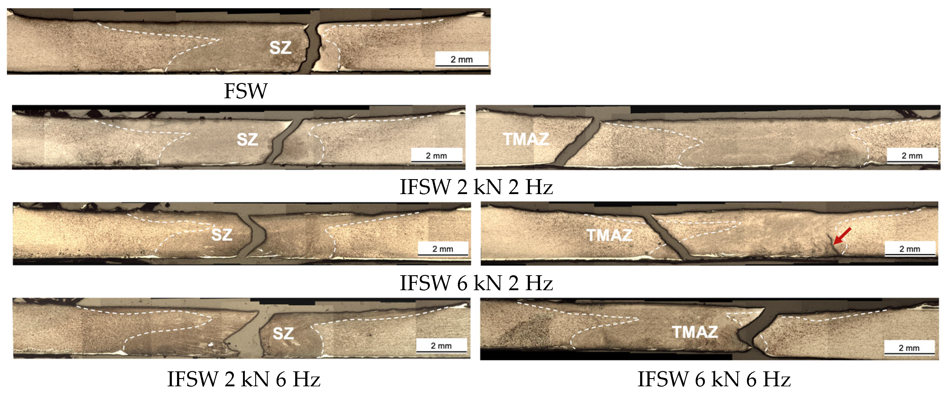
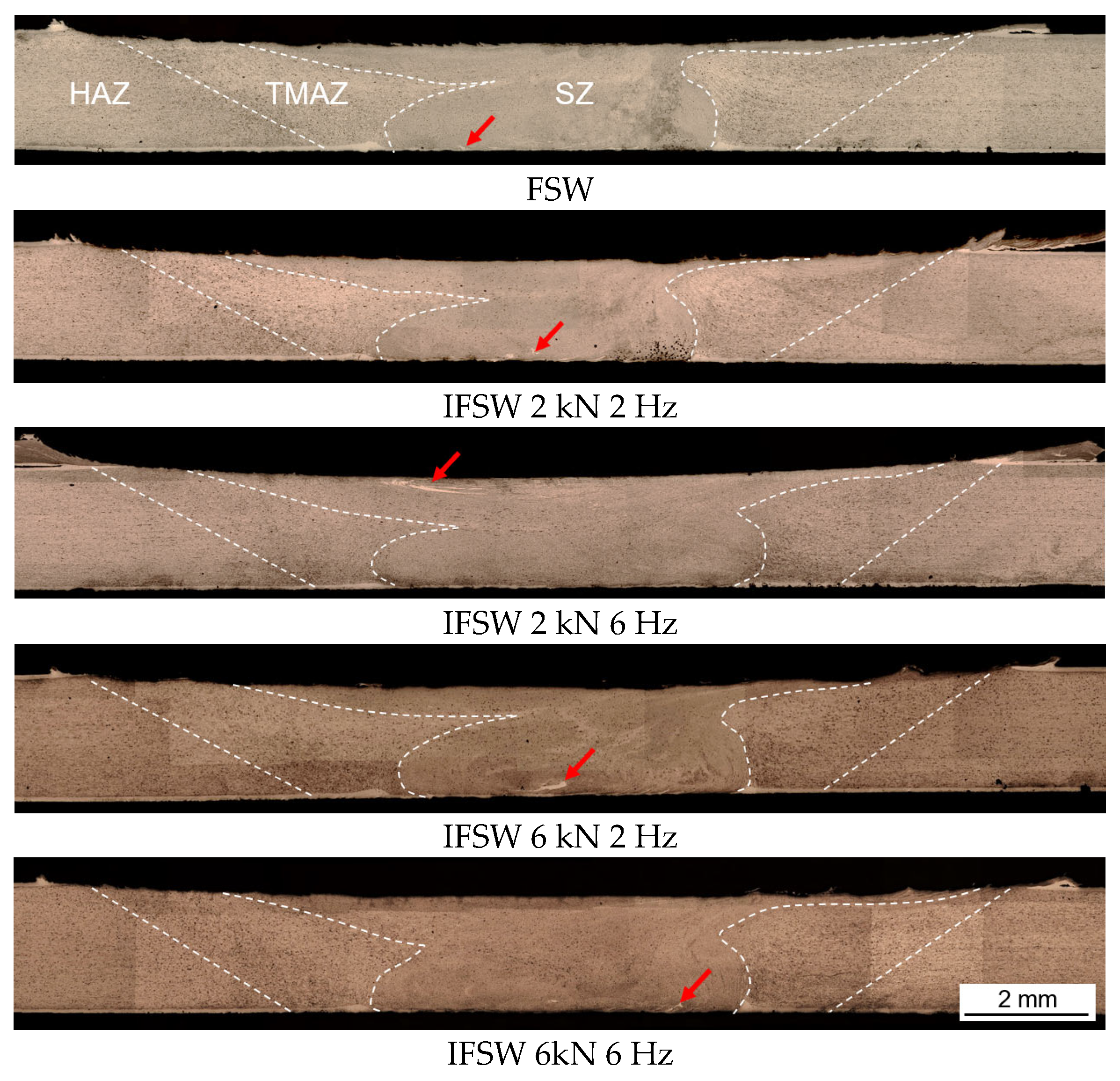
Figure 6 presents etched cross-sectional macrographs of the fabricated FSW and IFSW joints, with the boundaries between the distinct zones delineated by dotted white lines. The RS and AS are located on the left and right, respectively. A closer examination revealed fragments of the parent material embedded within the SZ, indicated by red arrows. Apart from this, no macroscopic defects such as lack of penetration, voids, or weld collapse were observed. Notably, root oxide lines (ROLs) were absent in all welds, likely due to their extensive fragmentation and uniform redistribution throughout the SZ.
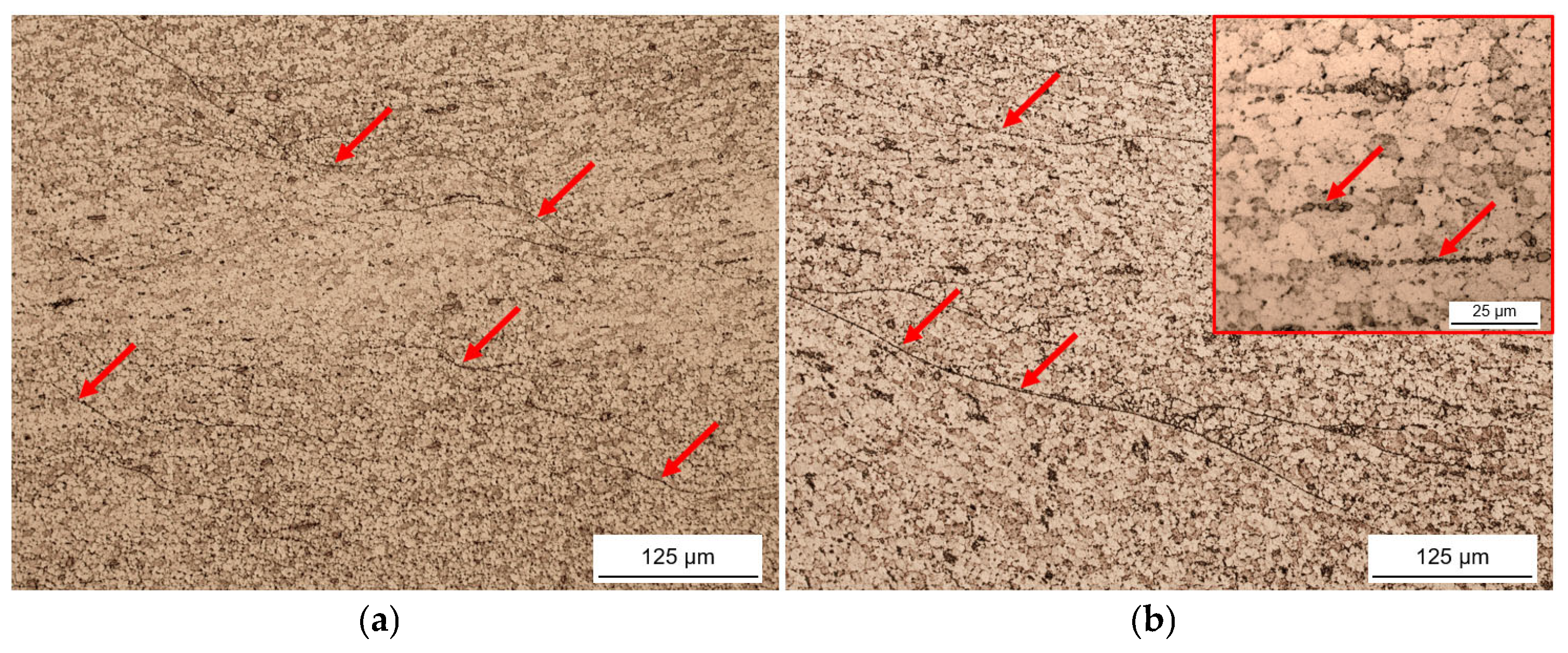
Within the SZ, linear segregation bands were observed, primarily concentrated in the upper region of all welds. They are highlighted by red arrows in
Figure 7. Higher-magnification imaging (inset in
Figure 7b) revealed that these bands consisted of agglomerated fine constituent particles, approximately 2 µm in size. Energy-dispersive X-ray spectroscopy (EDS) analysis confirmed that these particles originated from the parent material. In the base material, two distinct types of complex intermetallic compounds rich in Al, Fe, Mn, Si, and Cu were identified. The first type, primarily composed of Fe, Mn, and Si, is likely Al
12(Fe,Mn)
3Si, Wang and Starink [
32], while the second type exhibited a more complex composition of Al(Cu,Fe,Si)Mn.
Additionally, constituent particles approximately 0.5 µm in size were dispersed along grain boundaries, presumably contributing a pinning effect that inhibited grain growth. All evidence suggests that these particles underwent significant refinement—up to fivefold compared to their original state—and were uniformly redistributed through the stirring action during welding.
It remains challenging to definitively assess differences in the size and distribution of constituent particles between the FSW and IFSW joints due to their fine scale. However, the reciprocating motion of the IFSW tool likely modifies material flow, potentially enhancing particle redistribution and promoting further fragmentation.
3.5. Taylor Factor
It is well known that in FCC metals, atoms slip most easily along the {111} planes and <110> directions due to their dense atomic packing. Slip occurs when the shear stress in a slip system, caused by external loading, reaches a critical value. To quantify a material’s ability to deform plastically, the Taylor factor (
M) was introduced [
33]. It is defined as the ratio of flow stress under uniaxial loading (
σ) to the critical resolved shear stress (
τc) in the active slip system:
A lower Taylor factor means that less stress is required to activate slip, indicating that the grain orientation is more favorable for deformation. Conversely, a higher M value implies greater resistance to slip and is often associated with higher yield strength. In this context, M is used to predict the fracture location in FSW welds.
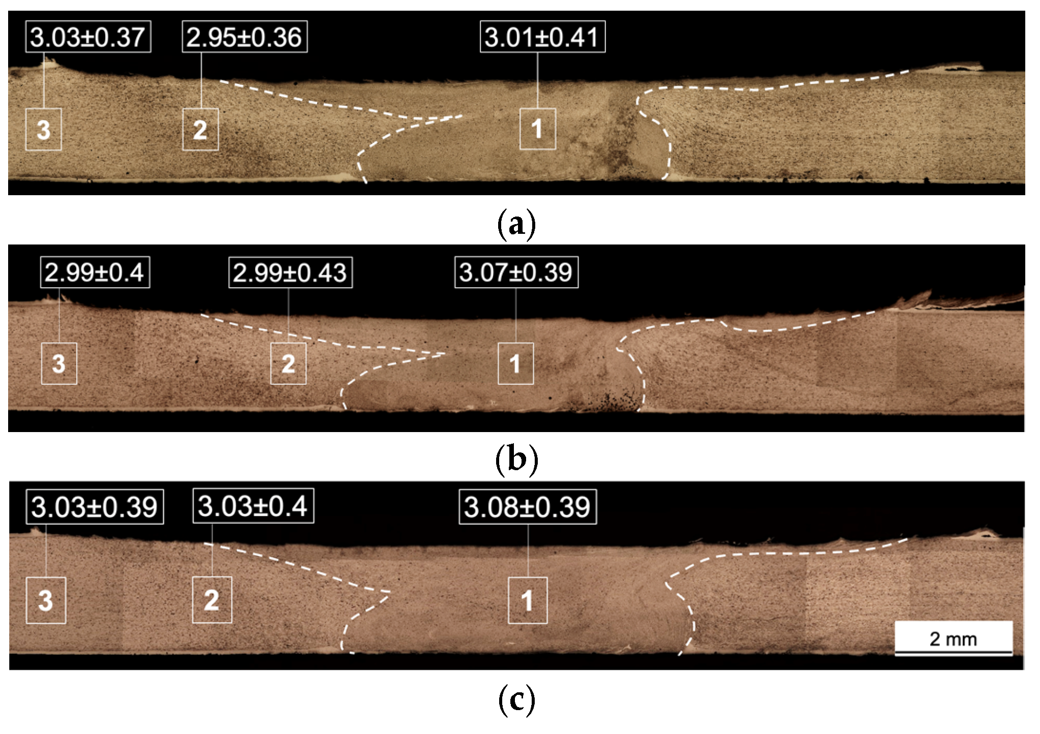
The average Taylor factor (
Mav) was calculated at selected locations in the FSW weld and in two IFSW welds with the lowest and highest impulse parameters. These values, along with standard deviations, are shown on the corresponding macrographs in
Figure 8. Although the standard deviation was relatively large, it was consistent across all measured locations.
In general, for all welds, Mav values gradually decreased from the stir zone (SZ) toward the base material (BM). This trend suggests that recrystallization in the SZ increased resistance to deformation, i.e., grain orientations became less favorable for slip compared to the BM. Additionally, the IFSW weld with higher impulse force and frequency exhibited consistently higher Mav values across all zones. This indicates that IFSW alters the crystallographic texture in the SZ, producing grains more resistant to plastic deformation compared to FSW.
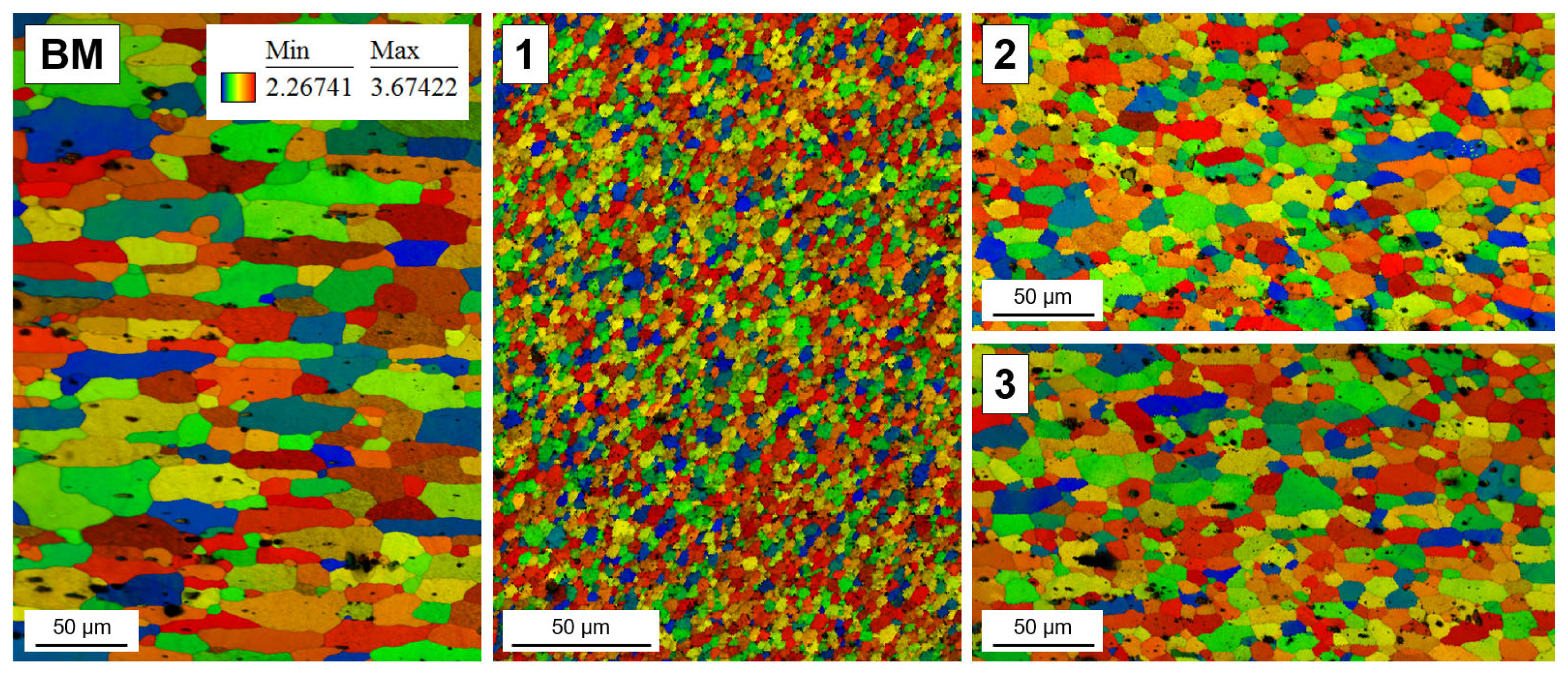
Taylor factor distribution maps (
Figure 9) were generated for the IFSW weld produced at 6 kN 6 Hz. It was chosen since all tensile specimens fractured in the TMAZ. These maps, unlike single
Mav values, highlight spatial distributions of M and can reveal concentrated bands that may indicate potential crack initiation zones. However, no such bands with low M values were found in any region. The SZ had a higher fraction of grains with large M values than the TMAZ and HAZ, which exhibited nearly identical distributions. This suggests that under transverse tensile loading, plastic deformation is more likely to initiate in the TMAZ or HAZ, explaining the preferential fracture in these regions. However, the exact failure location cannot be predicted solely based on M distribution.
The key conclusion is that there is no direct correlation between local Taylor factor values and fracture location in these welds. These findings align with those of Sato [
29,
30], who reported that strengthening precipitates dominate over Taylor factor effects in determining fracture behavior, particularly when a heterogeneous microhardness profile develops, as seen in non-heat-treatable aluminum alloys.
4. Discussion
4.1. Impact of the Metallurgical Evolution on the Tensile Behavior
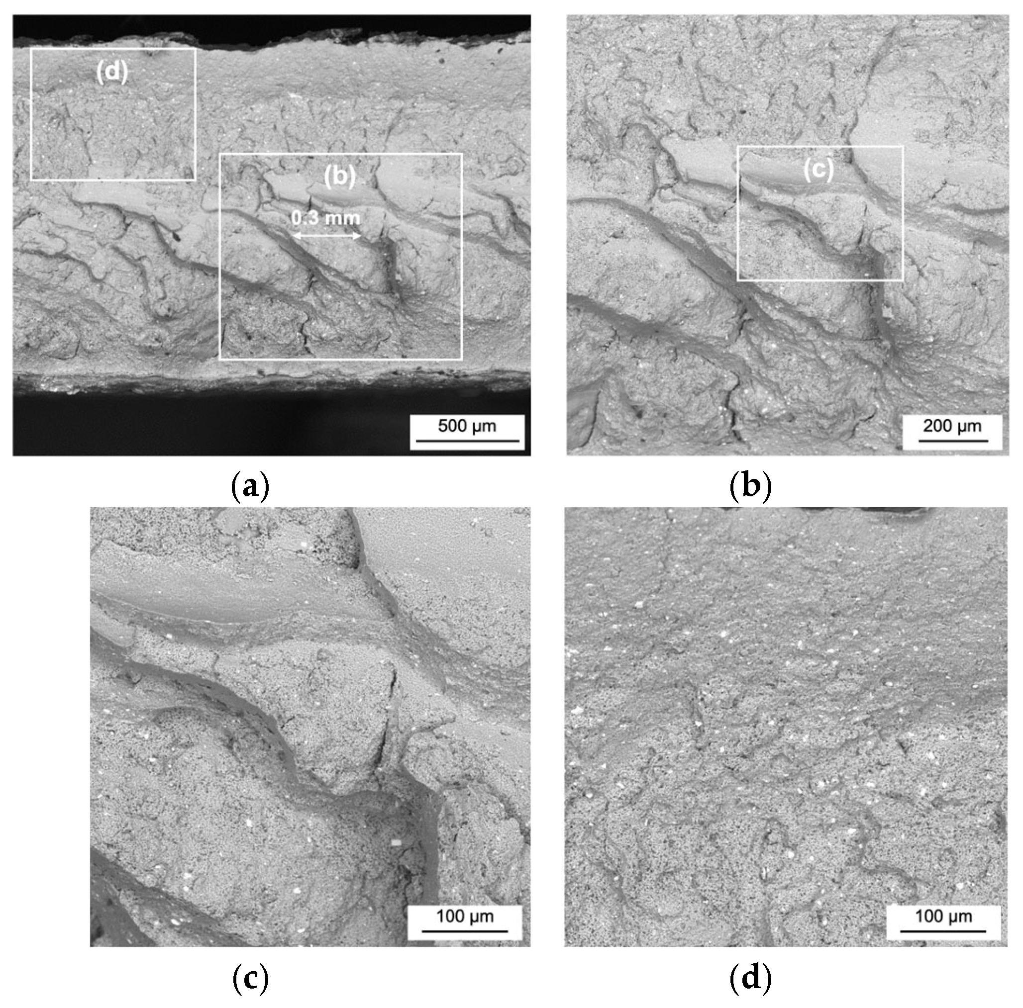
The fracture surfaces of tensile specimens were examined using SEM.
Figure 10 shows the fracture surface of the FSW weld that failed in the SZ. Sharp-edged grooves, 0.3–0.5 mm wide, were visible on the surface (
Figure 10a). At higher magnification, cracks were seen between the grooves (
Figure 10b). Fractured constituent particles visible as white dots appeared to be unevenly distributed. Boxes (c) and (d) highlight the analyzed areas. Notably, the fraction of intermetallic inclusions in the delaminated region, especially near the groove edges (
Figure 10c), was lower than in the upper weld area (
Figure 10d).
Although the upper weld region exhibited ductile fracture, the severe layering within the SZ likely caused fracture. This layering is attributed to the “weld pitch” (WP), defined as the ratio of welding speed (v, mm/min) to tool rotation speed (N, rpm), expressed in mm/rev. WP reflects the thickness of material deposited in one revolution and is often linked to the “onion ring” structure observed in SZ [
19,
24]. In this case, WP was 0.3 mm/rev (300 mm/min/1000 rpm), matching the observed layer thickness (
Figure 10a). This suggests insufficient stirring during welding, which compromised both strength and ductility.
Furthermore, uneven distribution of fragmented constituent particles likely weakened the material of the SZ. Their lower concentration in the delaminated region contrasts with the upper weld, where dense, fine particles formed deep dimples that enhanced ductility. In contrast, random particle distribution and low content contributed to brittle fracture along with severe layering. Interestingly, the previously discussed bands of intermetallic particles had no apparent effect on tensile properties.
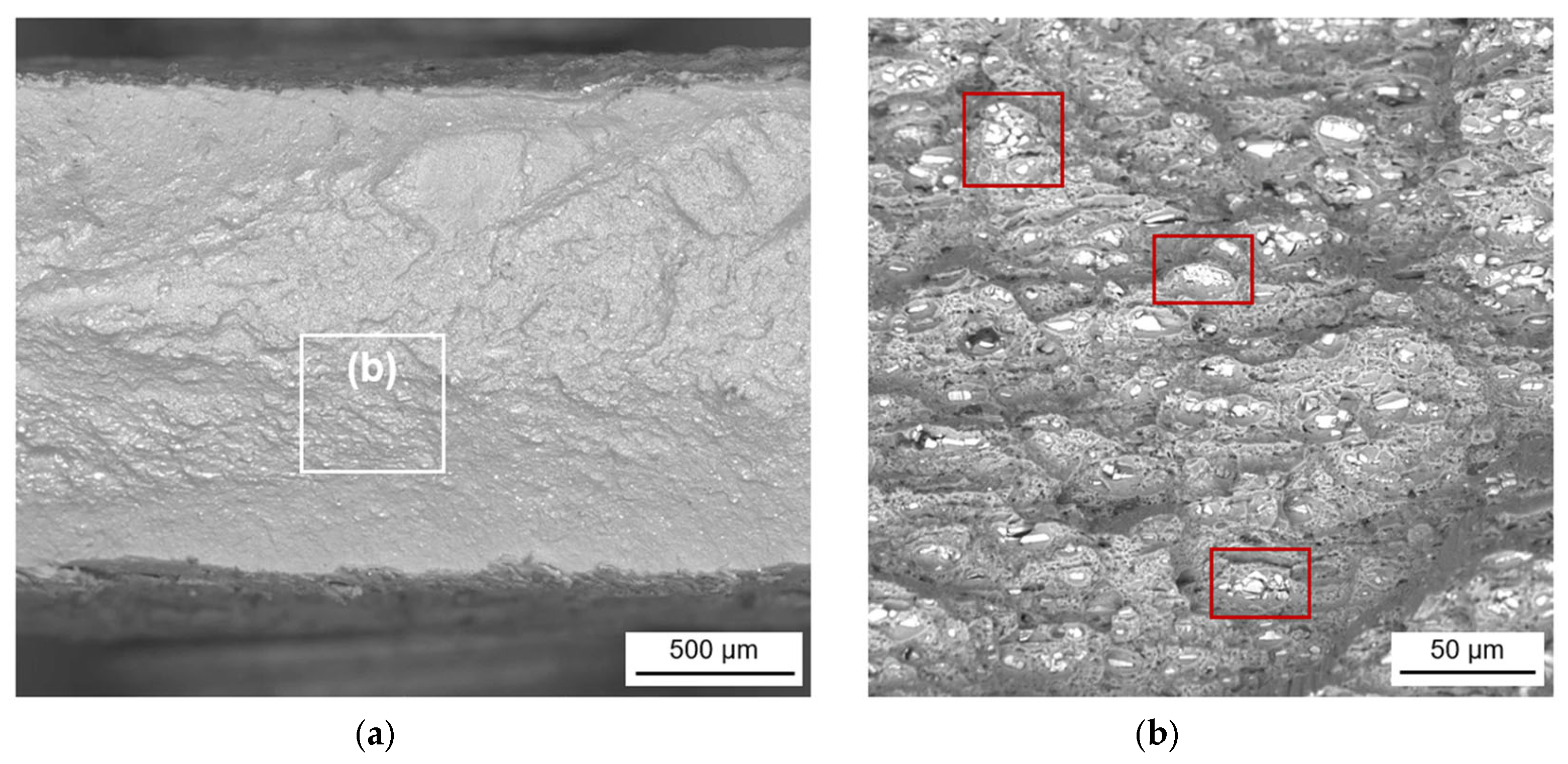
Since all IFSW joints fractured in the SZ displayed similar fracture features, only the 2 kN 2 Hz weld is presented in
Figure 11. Its fracture surface primarily showed numerous shallow dimples, indicating ductile behavior, indicated by red boxes. Unlike FSW, the constituent particles in IFSW were evenly distributed, and no severe delamination was observed. Despite identical welding and rotation speeds, and thus the same calculated WP, the reciprocating tool motion in IFSW likely enhanced the material mixing process.
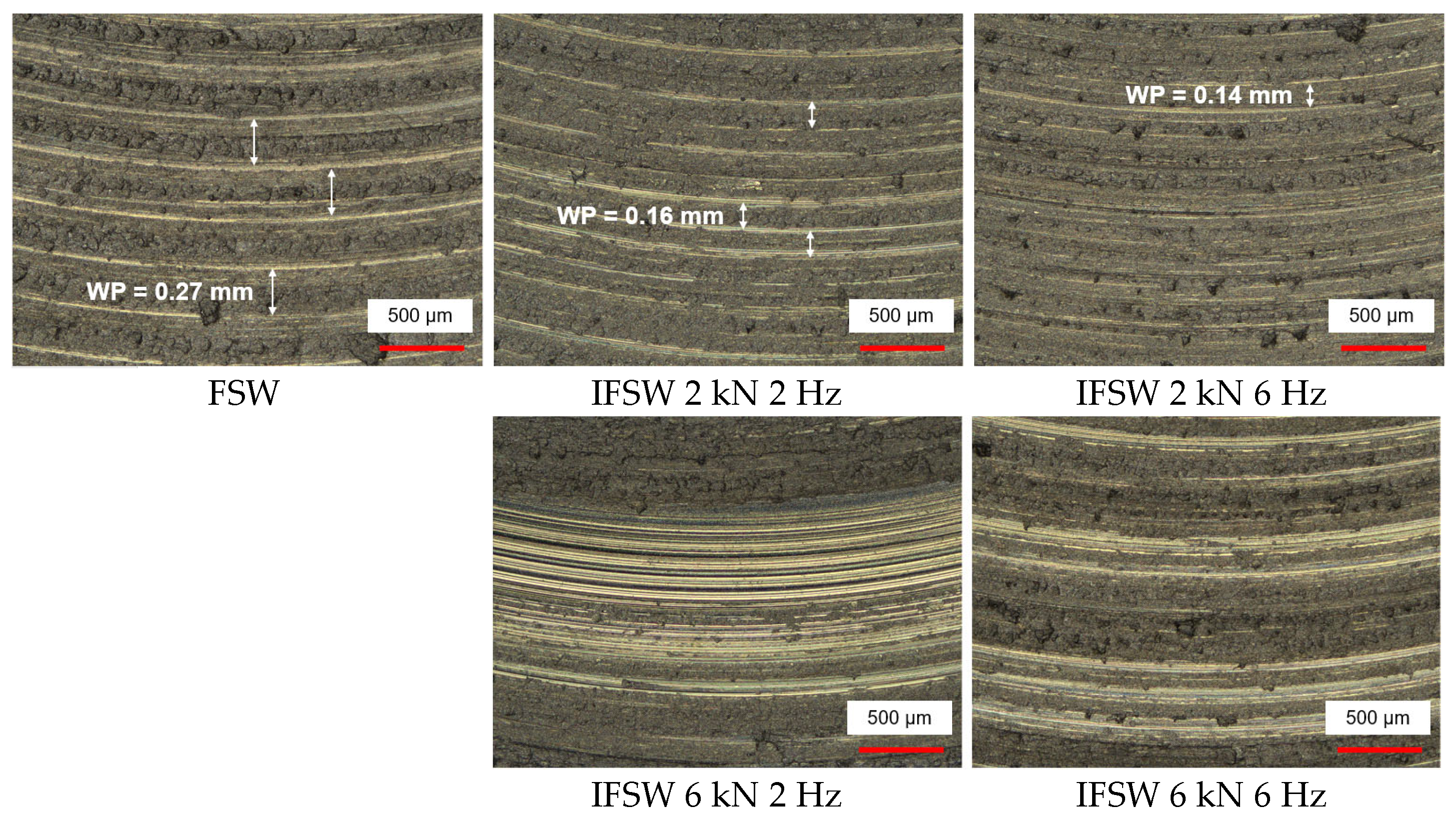
WP can also be estimated by measuring the distance between adjacent lamellas on the weld surface.
Figure 12 presents these measurements for FSW and IFSW joints. The WP in FSW was 0.27 mm, matching the theoretical value. In IFSW, this distance significantly decreased, especially with higher impulse frequencies. At the highest impulse settings, the WP became nearly immeasurable due to the extremely fine structure. This indicates that lower WP promotes more effective mixing and stronger bonding between layers.
Table 2 shows that with increasing impulse parameters, the fracture location shifted toward the TMAZ. This trend supports the idea that improved mixing from a reduced WP enhances joint performance. Still, some IFSW specimens fractured in the SZ, likely due to uneven mixing along the weld length.
Constituent particle bands remained concentrated in the upper weld zone, visible as clustered regions on the fracture surface (highlighted in
Figure 11b). However, no cracks initiated around these clusters, suggesting they did not directly influence fracture initiation.
In summary, the enhanced material mixing achieved by IFSW improved UTS and elongation compared to FSW. Additionally, the crystallographic texture in the SZ became more deformation-resistant, and particles were more evenly distributed. Both factors further contributed to increased strength and ductility.
4.2. Impact of the Metallurgical Evolution on the Fatigue Behaviour
Fatigue fractures in most FSW and IFSW joints occurred in the stir zone (SZ), though a few specimens failed in the TMAZ near the SZ/TMAZ interface. Previous studies suggest that crack initiation in the SZ significantly reduces fatigue life in FSW joints. In contrast, failure in the TMAZ or HAZ is typically attributed to decohesion of large S-phase particles [
34] or hard intermetallic and dispersoid inclusions [
35]. Therefore, fractographic analysis focused on the SZ to investigate the root causes of fatigue degradation.
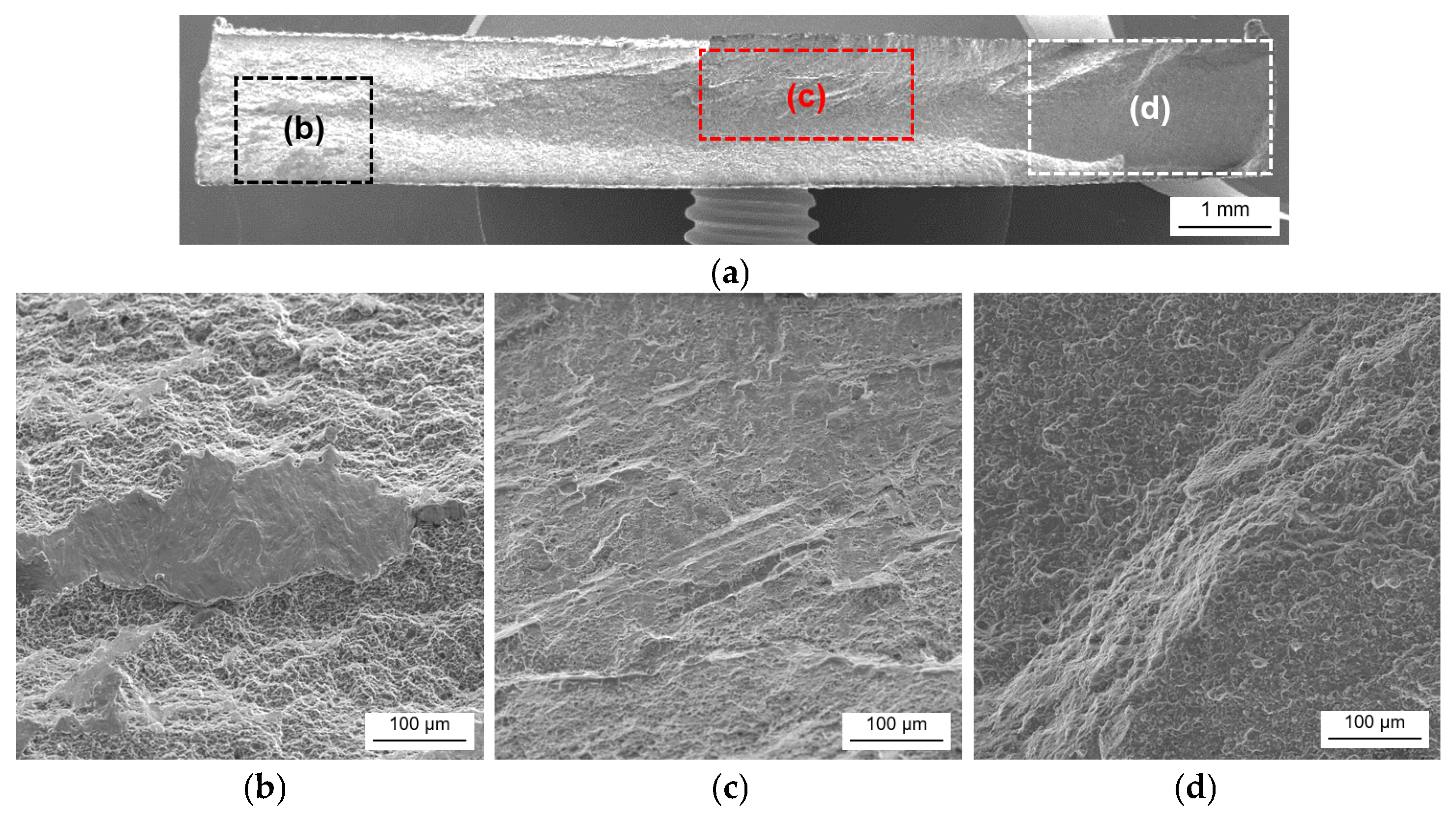
Fatigue fracture typically proceeds through three stages: crack initiation (I), crack growth (II), and final fracture (III).
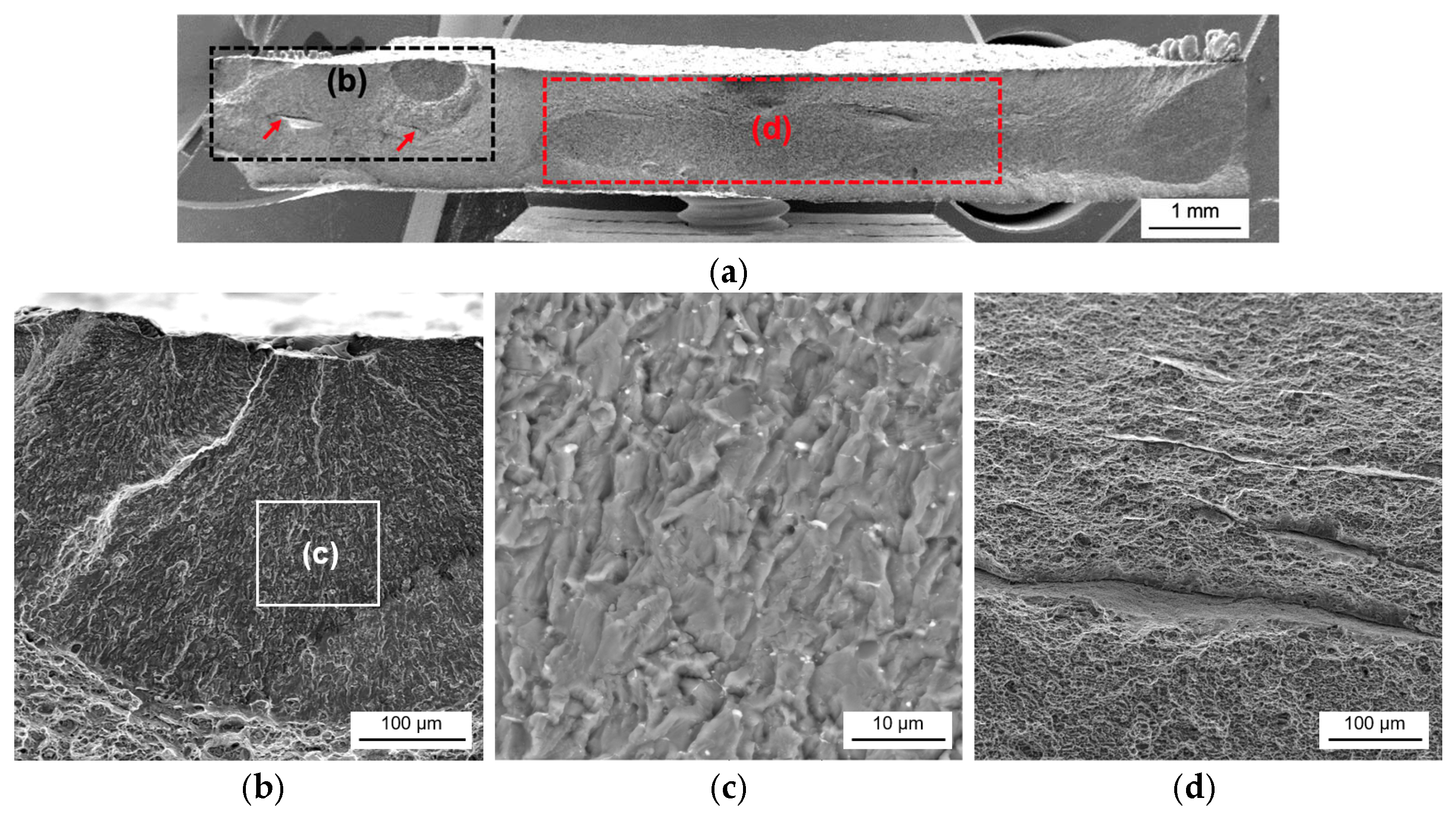
Figure 13a presents an overview of a fractured FSW specimen, with all stages labeled. In the initiation zone (I), islands of fatigue striations were observed (
Figure 13b). These islands were unplasticized metal fragments embedded in the weld, previously identified at the bottom of the weld in macrographs (
Figure 6). Their cleavage-like fracture surfaces suggest that failure initiated at the boundary between the ductile matrix and these brittle particles. Delamination was also found in the initiation regions of other FSW specimens, confirming that SZ imperfections were a key trigger for fatigue failure. The crack then propagated through the weld center (II), showing a brittle fracture surface (
Figure 13c). The final fracture zone (III) was rough, indicative of shear failure under rapid loading (
Figure 13d).
Interestingly, impulse welds produced at 2 Hz exhibited similar fracture features, including brittle islands in the crack initiation zone, also visible in the corresponding macrographs (
Figure 6). Thus, in both FSW and IFSW (2 Hz) joints, fatigue failure was primarily initiated by metallic inclusions in the SZ, resulting in premature failure and reduced fatigue resistance.
Figure 14a shows the fracture surface of the IFSW 2 kN 6 Hz joint, which demonstrated the best fatigue performance among the studied welds. The three-stage fracture designation remained the same.
In crack initiation zone (I), a round surface chip was observed, with deep cracks extending along the weld (highlighted by red arrows in
Figure 14a).
Figure 14b, a close-up of the chip, reveals cracks propagating from its surface to its base before splitting. The chip’s surface displayed clear fatigue striations (
Figure 14c). Its formation is likely linked to delamination between surface lamellas, supported by the curved crack line seen in
Figure 5. These cracks are believed to originate from non-plasticized metal strips, as seen in the 2 kN 6 Hz macrograph.
Crack growth in stage II (
Figure 14d) occurred along the weld center, again related to trapped metal strips. Aside from these features, the rest of the fracture surface showed fine dimples, typical of ductile behavior. The final fracture zone resembled that of FSW but was smaller, suggesting a longer ductile propagation phase.
The IFSW 6 kN 6 Hz joint, showing superior fatigue life at higher stress amplitudes, displayed a similar fracture pattern with surface chips but no initiation cracks. This suggests that high-frequency impulses promote efficient material mixing, mitigating the negative effects of defects. However, residual metal strips in the SZ can still limit fatigue strength, indicating that further optimization of impulse parameters is needed. The increased ductility in the SZ of IFSW joints also supports extended crack propagation and overall fatigue endurance.
Defects like voids, inclusions, and surface cracks have long been recognized as critical to fatigue performance in FSW aluminum alloys. For example, root flaws [
36] and surface roughness [
37] have been cited as detrimental. Interestingly, surface roughness in this study did not correlate with fatigue stress. Booth and Sinclair [
34] attributed crack deflection in the SZ to hardness variations caused by flow pattern discontinuities, linked to differences in second-phase particle concentrations. In the present work, linear intermetallic segregations had no observable effect on tensile or fatigue properties, as no signs of these bands appeared on the fracture surfaces. Thus, fatigue damage in both FSW and IFSW welds was not associated with intermetallic segregations.
5. Conclusions
In this study, AA2024-T351 aluminum alloy sheets were butt-welded using both conventional friction stir welding (FSW) and impulse friction stir welding (IFSW) methods to investigate the influence of process parameters on tensile and fatigue behavior as well as on fracture mechanisms.
Impulse friction stir welding (IFSW) significantly improved the tensile properties of AA2024-T351 welds compared to conventional FSW, with tensile strength increases exceeding 20% and elongation values up to five times higher depending on impulse parameters.
Fracture location under tensile load was influenced by both microstructural and mechanical factors. FSW joints consistently failed in the SZ, while IFSW joints exhibited failure in either the SZ or the TMAZ, depending on the impulse settings. Weld pitch (WP) analysis confirmed that reduced WP achieved through higher impulse frequency enhanced material mixing and interlayer bonding, contributing to better mechanical performance. Uneven distribution of constituent particles along the weld is believed to strengthen this effect. However, intermetallic bands in the SZ were not directly responsible for mechanical degradation.
Taylor factor (M) analysis indicated higher values in IFSW joints, suggesting improved resistance to deformation. However, no direct correlation was found between M distribution and fracture location, emphasizing the overriding influence of other metallurgical factors.
Fatigue performance improved with IFSW, particularly at higher impulse frequencies. The IFSW 2 kN 6 Hz joint showed the best fatigue behavior, delaying the onset of failure even under prolonged cyclic loading. Crack initiation in both FSW and IFSW was associated with unplasticized metal inclusions and surface defects in the SZ. However, high-frequency impulses are believed to promote efficient material mixing, mitigating the negative effects of defects.
The results demonstrate that IFSW offers superior control over weld quality, enabling tailored mechanical properties through adjustment of impulse parameters—making it a promising technique for aerospace-grade aluminum alloys under demanding mechanical loads. It is recommended to use lower force and higher frequency during welding to achieve improved mechanical performance.
Author Contributions
Conceptualization, I.M., A.O. and N.D.; methodology, I.M. and A.N.; software, I.M.; validation, A.O., A.N., N.D. and V.M.; formal analysis, I.M. and A.O.; investigation, I.M., A.O. and A.N.; resources, V.M.; data curation, I.M. and A.O.; writing—original draft preparation, I.M.; writing—review and editing, I.M., A.O. and N.D.; visualization, I.M.; supervision, A.N. and N.D.; project administration, I.M. and V.M. All authors have read and agreed to the published version of the manuscript.
Funding
This research received no external funding.
Data Availability Statement
The data can be provided upon request by the authors.
Conflicts of Interest
The authors declare no conflicts of interest.
Abbreviations
The following abbreviations are used in this manuscript:
| AS | advancing side |
| BM | base material |
| EBSD | electron backscatter diffraction |
| EDS | energy-dispersive X-ray spectroscopy |
| FSW | friction stir welding |
| HAZ | heat-affected zone |
| IFSW | impulse friction stir welding |
| NA | natural aging |
| ROL | remnant oxide line |
| RS | retreating side |
| SEM | scanning electron microscope |
| SZ | stir zone |
| TMAZ | thermo-mechanically affected zone |
| WP | weld pitch |
References
- Shukla, A.K.; Baeslack, W.A. Effect of process conditions on microstructure evolution and mechanical properties of friction stir welded thin sheet 2024-T3. In Proceedings of the 6th International Symposium on Friction Stir Welding, Saint Sauveur, QC, Canada, 10–13 October 2006. [Google Scholar]
- Zhang, Z.; Xiao, B.L.; Ma, Z.Y. Hardness recovery mechanism in the heat-affected zone during long-term natural aging and its influence on the mechanical properties and fracture behavior of friction stir welded 2024Al-T351 joints. Acta Mater. 2014, 73, 227–239. [Google Scholar] [CrossRef]
- Morita, T.; Yamanaka, M. Microstructural evolution and mechanical properties of friction-stir-welded Al-Mg-Si joint. Mater. Sci. Eng. A 2014, 595, 196–204. [Google Scholar] [CrossRef]
- Genevois, C.; Deschamps, A.; Denquin, A.; Doisneau-Cottignies, B. Quantitative investigation of precipitation and mechanical behaviour for AA2024 friction stir welds. Acta Mater. 2005, 53, 2447–2458. [Google Scholar] [CrossRef]
- Zhou, C.; Yang, X.; Luan, G. Effect of oxide array on the fatigue property of friction stir welds. Scr. Mater. 2006, 54, 1515–1520. [Google Scholar] [CrossRef]
- Chen, H.B.; Wang, J.F.; Zhen, G.D.; Chen, S.B.; Lin, T. Effects of initial oxide on microstructural and mechanical properties of friction stir welded AA2219 alloy. Mater. Des. 2015, 86, 49–54. [Google Scholar] [CrossRef]
- Niu, P.; Li, W.; Zhang, Z.; Wang, F.; Feng, Y.; Fu, M. Significant effect of oxide on mechanical properties of friction-stir-welded AA2024 joints. Sci. Technol. Weld. Join. 2016, 22, 66–70. [Google Scholar] [CrossRef]
- Liu, H.J.; Chen, Y.C.; Feng, J.C. Effect of zigzag line on the mechanical properties of friction stir welded joints of an Al-Cu alloy. Scr. Mater. 2006, 55, 231–234. [Google Scholar] [CrossRef]
- Růžek, R.; Kadlec, M.; Nováková, L. Influence of the kissing bond defect on the fatigue life in friction stir welds of 2024 aluminium alloy. Cienc. Tecnol. Mater. 2015, 27, 92–99. [Google Scholar] [CrossRef]
- Laska, A.; Szkodo, M.; Cavaliere, P.; Moszczyńska, D.; Mizera, J. Analysis of residual stresses and dislocation density of AA6082 butt welds produced by friction stir welding. Metall. Mater. Trans. A 2022, 54, 211–225. [Google Scholar] [CrossRef]
- Bussu, G.; Irving, P.E. The role of residual stress and heat affected zone properties on fatigue crack propagation in friction stir welded 2024-T351 aluminium joints. Int. J. Fatigue 2002, 25, 77–88. [Google Scholar] [CrossRef]
- John, R.; Jata, K.V.; Sadananda, K. Residual stress effects on near-threshold fatigue crack growth in friction stir welds in aerospace alloys. Int. J. Fatigue 2003, 25, 939–948. [Google Scholar] [CrossRef]
- Altenkirch, J.; Steuwer, A.; Peel, M.J.; Withers, P.J.; Williams, S.W.; Poad, M. Mechanical tensioning of high-strength aluminum alloy friction stir welds. Metall. Mater. Trans. A 2008, 39, 3246–3259. [Google Scholar] [CrossRef]
- Salem, H.G. Friction stir weld evolution of dynamically recrystallized AA 2095 weldments. Scr. Mater. 2003, 49, 1103–1110. [Google Scholar] [CrossRef]
- Sutton, M.A.; Yang, B.; Reynolds, A.P.; Taylor, R. Microstructural studies of friction stir welds in 2024-T3 aluminum. Mater. Sci. Eng. A 2002, 323, 160–166. [Google Scholar] [CrossRef]
- Mishra, R.S.; Mahoney, M.W. Friction Stir Welding and Processing; ASM International: Materials Park, OH, USA, 2007; p. 368. [Google Scholar]
- Booth, D.P.P.; Starink, M.J.; Sinclair, I. Analysis of local microstructure and hardness of 13 mm gauge 2024-T351 AA friction stir welds. Mater. Sci. Technol. 2007, 23, 276–284. [Google Scholar] [CrossRef]
- Yang, B.; Yan, J.; Sutton, M.A.; Reynolds, A.P. Banded microstructure in AA2024-T351 and AA2524-T351 aluminum friction stir welds. Part I. Metallurgical studies. Mater. Sci. Eng. A 2004, 364, 55–65. [Google Scholar] [CrossRef]
- Sutton, M.A.; Reynolds, A.P.; Yang, B.; Taylor, R. Mixed mode I/II fracture of 2024-T3 friction stir welds. Eng. Fract. Mech. 2003, 70, 2215–2234. [Google Scholar] [CrossRef]
- Sutton, M.A.; Reynolds, A.P.; Yang, B.; Yan, J. Banded microstructure in 2024-T351 and 2524-T351 aluminum friction stir welds. Part II. Mechanical characterization. Mater. Sci. Eng. A 2004, 364, 66–74. [Google Scholar] [CrossRef]
- Norman, A.F.; Brough, I.; Prangnell, P.B. High resolution EBSD analysis of the grain structure in an AA2024 friction stir weld. Mater. Sci. Forum 2000, 331, 1713–1718. [Google Scholar] [CrossRef]
- Aydin, H.; Bayram, A.; Uǧuz, A.; Akay, K.S. Tensile properties of friction stir welded joints of 2024 aluminum alloys in different heat-treated-state. Mater. Des. 2009, 30, 2211–2221. [Google Scholar] [CrossRef]
- Chen, Y.; Liu, H.; Feng, J. Friction stir welding characteristics of different heat-treated-state 2219 aluminum alloy plates. Mater. Sci. Eng. A 2006, 420, 21–25. [Google Scholar] [CrossRef]
- Sutton, M.A.; Reynolds, A.P.; Yang, B.; Taylor, R. Mode I fracture and microstructure for 2024-T3 friction stir welds. Mater. Sci. Eng. A 2003, 354, 6–16. [Google Scholar] [CrossRef]
- Fonda, R.W.; Bingert, J.F. Microstructural evolution in the heat-affected zone of a friction stir weld. Metall. Mater. Trans. A 2004, 35, 1487–1499. [Google Scholar] [CrossRef]
- Tayon, W.A.; Domack, M.S.; Hoffman, E.K.; Hales, S.J. Texture evolution within the thermomechanically affected zone of an Al-Li alloy 2195 friction stir weld. Metall. Mater. Trans. A 2013, 44, 4906–4913. [Google Scholar] [CrossRef]
- Xu, W.F.; Wu, X.K.; Ma, J.; Lu, H.J.; Luo, Y.X. Abnormal fracture of 7085 high strength aluminum alloy thick plate joint via friction stir welding. J. Mater. Res. Technol. 2019, 8, 6029–6040. [Google Scholar] [CrossRef]
- Tao, Y.; Ni, D.R.; Xiao, B.L.; Ma, Z.Y.; Wu, W.; Zhang, R.X.; Zeng, Y.S. Origin of unusual fracture in stirred zone for friction stir welded 2198-T8 Al-Li alloy joints. Mater. Sci. Eng. A 2017, 693, 1–13. [Google Scholar] [CrossRef]
- Sato, Y. Relationship between mechanical properties and microstructure in friction stir welded Al alloys. Weld. Int. 2003, 17, 706–709. [Google Scholar] [CrossRef]
- Sato, Y.S.; Kokawa, H. Distribution of tensile property and microstructure in friction stir weld of 6063 aluminum. Metall. Mater. Trans. A 2001, 32, 3023–3031. [Google Scholar] [CrossRef]
- Morozova, I.; Królicka, A.; Obrosov, A.; Yang, Y.; Doynov, N.; Weiß, S.; Michailov, V. Precipitation phenomena in impulse friction stir welded 2024 aluminium alloy. Mater. Sci. Eng. A 2022, 852, 143617. [Google Scholar] [CrossRef]
- Wang, S.C.; Starink, M.J. Precipitates and intermetallic phases in precipitation hardening Al-Cu-Mg-(Li) based alloys. Int. Mater. Rev. 2005, 50, 193–215. [Google Scholar] [CrossRef]
- Taylor, G.I. Strains in crystalline aggregate. In Verformung und Fliessen des Festkörpers/Deformation and Flow of Solids; Grammel, R., Ed.; Springer: Berlin/Heidelberg, Germany, 1956; pp. 3–12. [Google Scholar]
- Booth, D.; Sinclair, I. Fatigue of friction stir welded 2024-T351 aluminium alloy. Mater. Sci. Forum 2002, 396–402, 1671–1676. [Google Scholar] [CrossRef]
- Feng, A.H.; Chen, D.L.; Ma, Z.Y. Microstructure and low-cycle fatigue of a friction-stir-welded 6061 aluminum alloy. Metall. Mater. Trans. A 2010, 41, 2626–2641. [Google Scholar] [CrossRef]
- Zhou, C.; Yang, X.; Luan, G. Effect of root flaws on the fatigue property of friction stir welds in 2024-T3 aluminum alloys. Mater. Sci. Eng. A 2006, 418, 155–160. [Google Scholar] [CrossRef]
- Lomolino, S.; Tovo, R.; dos Santos, J. On the fatigue behaviour and design curves of friction stir butt-welded Al alloys. Int. J. Fatigue 2005, 27, 305–316. [Google Scholar] [CrossRef]
| Disclaimer/Publisher’s Note: The statements, opinions and data contained in all publications are solely those of the individual author(s) and contributor(s) and not of MDPI and/or the editor(s). MDPI and/or the editor(s) disclaim responsibility for any injury to people or property resulting from any ideas, methods, instructions or products referred to in the content. |
© 2025 by the authors. Licensee MDPI, Basel, Switzerland. This article is an open access article distributed under the terms and conditions of the Creative Commons Attribution (CC BY) license (https://creativecommons.org/licenses/by/4.0/).


 ,
, 

