Article

Advanced Control Strategy for Induction Motors Using Dual SVM-PWM Inverters and MVT-Based Observer

1
Laboratory of Applied Automation and Industrial Diagnostics (LAADI), Department of Electrical Engineering, Faculty of Science and Technology, Ziane Achour University, Djelfa 17000, Algeria
2
Electrical Engineering Department, Laboratory of New Technologies and Local Development (LNTDL), Hamma Lakhdar University of El Oued, El Oued 39000, Algeria
3
Center for Energy Transition, Universidad San Sebastián, Santiago 8420524, Chile
4
Department of Electrical Engineering, Faculty of Engineering, Assiut University, Assiut 71516, Egypt
5
Chair of High-Power Converter Systems, Technical University of Munich, 80333 Munich, Germany
*
Authors to whom correspondence should be addressed.
Machines 2025, 13(6), 520; https://doi.org/10.3390/machines13060520
Submission received: 8 April 2025 / Revised: 30 May 2025 / Accepted: 11 June 2025 / Published: 14 June 2025
(This article belongs to the Section Electromechanical Energy Conversion Systems)

Abstract

This paper introduces a novel field-oriented control (FOC) strategy for an open-end stator three-phase winding induction motor (OEW-TP-IM) using dual space vector modulation-pulse width modulation (SVM-PWM) inverters. This configuration reduces common mode voltage at the motor’s terminals, enhancing efficiency and reliability. The study presents a backstepping control approach combined with a mean value theorem (MVT)-based observer to improve control accuracy and stability. Stability analysis of the backstepping controller for key control loops, including flux, speed, and currents, is conducted, achieving asymptotic stability as confirmed through Lyapunov’s methods. An advanced observer using sector nonlinearity (SNL) and time-varying parameters from convex theory is developed to manage state observer error dynamics effectively. Stability conditions, defined as linear matrix inequalities (LMIs), are solved using MATLAB R2016b to optimize the observer’s estimator gains. This approach simplifies system complexity by measuring only two line currents, enhancing responsiveness. Comprehensive simulations validate the system’s performance under various conditions, confirming its robustness and effectiveness. This strategy improves the operational dynamics of OEW-TP-IM machine and offers potential for broad industrial applications requiring precise and reliable motor control.

1. Introduction

This research paper explores advanced control strategies for a three-phase induction machine with open-end winding (OEW-TP-IM), which is tailored for applications requiring reduced global power per phase and heightened overall system security [1,2]. The OEW-TP-IM’s complexity is elevated by its nonlinear nature and time-varying parameters, particularly in speed variation applications where rotor variable states are not readily accessible. This complexity complicates real-time control, demanding precise information on the rotor’s position [3], speed and flux [4,5,6], and parameters [7,8,9,10] to effectively segment the machine into subsystems for torque and flux management within a field-oriented control framework. Traditional research in this area has predominantly utilized linear models.
However, the dynamic nature of these systems and their wide operational conditions necessitate the use of non-linear models for an accurate depiction. Despite their detailed representation, non-linear models generally lack the ability to provide unified solutions for system regulation and estimation. This limitation has prompted researchers to transform these complex, coupled systems into more standardized forms such as bilinear or Lipschitz configurations facilitating the application of multiple advanced control and estimation techniques [11,12,13]. A significant aspect of this study is addressing critical system faults, such as short circuits and parameter variations, using robust backstepping control techniques [7,9]. This approach substantially reduces both internal and external disturbances, thus preventing system instability and enhancing performance. The effectiveness of these control techniques in maintaining system stability under both normal and fault conditions is empirically supported and theoretically validated through Lyapunov’s theory. In addition to conventional control mechanisms, advanced control strategies for induction motors, specifically focusing on methods like backstepping control, sliding mode control, and model reference adaptive systems (MRAS). These methods are crucial for applications requiring precise control, reduced power per phase, and increased system security. The research primarily addresses the challenges posed by the nonlinear nature and time-varying parameters of induction motors, especially in speed variation applications where rotor states are not easily accessible.
This paper explores sensorless control techniques to circumvent the drawbacks associated with traditional sensors. These sensors, often plagued by placement issues, reduce control accuracy and system reliability [9]. Sensorless approaches have been proposed and widely implemented, aiming to reduce hardware complexity and increase the robustness and reliability of the system.
This research also reviews various observer-based control methods that have been explored in technical studies. Notably, it examines backstepping controller designs incorporating high-gain observers to manage the complex dynamics of induction motors [14]. This approach improves the accuracy of rotor flux and speed estimation, providing a more precise control system. A novel adaptive control method for induction motors based on the backstepping approach, treated in [7,15], ensures robust performance against parameter variations and external disturbances. Furthermore, a sensorless speed control technique utilizing model reference adaptive systems (MRAS) in conjunction with a flux sliding mode observer was introduced in [4]. This technique enhances the estimation accuracy of rotor flux and speed without relying on physical sensors, thereby increasing the system’s reliability and performance.
Overall, these advanced observer-based control methods significantly contribute to the robustness and precision of induction motor control systems, addressing key challenges posed by nonlinear dynamics and varying operational conditions. By integrating these techniques, the research aims to develop more reliable and efficient control strategies for complex induction motor systems, facilitating their broader application in various industrial contexts.
Other techniques aim to provide robust and adaptive control and estimation, addressing the precise estimation of machine states and parameters but facing significant computational challenges. In [5], an adaptive sliding-mode speed observer for induction motors under backstepping control was explored, enhancing speed estimation accuracy and system robustness. In [3], an adaptive backstepping observer for online rotor resistance adaptation was studied, focusing on maintaining performance despite parameter variations. In [16], sensorless backstepping control employing an adaptive Luenberger observer with a three-level NPC inverter was explored, eliminating the necessity for physical sensors and enhancing system efficiency. Ref. [17] explored sensorless predictive control techniques, providing a proactive approach to system management. Finally, ref. [18] discussed a robust extended H∞ observer, while [19] addressed a robust H∞ controller using the MVT approach. These studies highlight the ongoing efforts to develop advanced control methods that balance accuracy, robustness, and computational feasibility, contributing to the broader application and reliability of induction motor systems in various industrial contexts.
In [20], the authors presented a fuzzy logic (FLC)-based speed control of indirect field oriented (IFOC) for the control of doubly star open-end winding induction motor (DS-OEWIM) is presented. The authors in [21] focused on the application of a model predictive control approach for open-end winding induction motors with common DC link-fed inverters to ensure the suppression of the zero-sequence current component. A discontinuous pulse width modulation (DPWM) scheme was applied to reduce the switching loss of a single DC-link dual two-level inverter fed an open-end winding (OW) induction motor (IM) under motor control was presented [22]. In [23], the stability problem of adaptive full-order observer (AFO) for speed-sensorless direct torque control (DTC) of an open-end winding five-phase induction motor was discussed and analyzed. The same authors presented an advanced field-oriented control (FOC) for an open-end stator winding six-phase induction motor (SPIM-OESW) with fuzzy logic (FL) speed controller [24]. In [25], the authors proposed a new advanced sliding mode control (SMC) based on backstepping approach for an open-end stator windings dual-stator induction motor (DSIM-OESW) under low speed condition based on sensorless approach. a new control scheme for the extension of the speed range of dual-inverter-fed induction motor drives with open-end stator windings was proposed. In this proposal, the two inverters connected to the two winding sides were powered by a DC power source and a capacitor, respectively [26]. The authors of [27] presented different control strategies involving the open-end winding induction motor configuration fed by dual two-level inverters based on achieving controllable power sharing between two isolated power sources without using the DC/DC converter. A torque estimator based on Luenberger observer applied to an EV driven by an open-end winding induction motor (OEWIM) fed by two inverters was developed and experimentally implemented and validated [28]. Recently, an improved artificial neural network (ANN)-based direct torque control (DTC) algorithm was applied for open-end winding induction motor (OEWIM) sensorless drives. This proposed ANN-based DTC was tested by simulation and validated through experimental tests [29]. The authors of [9] proposed a sensorless field-oriented control (FOC) of an open-end stator winding five-phase induction motor (OESW-FPIM) where the FOC technique was associated with dual space vector modulation (SVM) to provide a constant switching frequency and to ensure lower harmonics mitigation. Indeed, the authors further proposed a simple hybrid observer by combining a model reference adaptive system (MRAS) and a sliding mode (SM) observer, whereas the effectiveness of the proposed control was validated in real-time based on a hardware-in-the-loop (HIL) platform. Furthermore, ref. [30] provided a literature review on open-end winding induction machine drives (OEWIMD) using two 2-level inverters; the main advantages of this topology are presented under different control approaches that were all thoroughly explored.
On the other side, the mean value theory (MVT) approach recently proved that it allows removing not only the mismatching terms in the estimation error dynamics but also streamlines the factorization of the estimation error dynamics by ensuring the direct proportionality with the estimation error [31]. The authors in [32] studied the stability problem of a nonlinear system described by a Takagi–Sugeno fuzzy (TSF) model with unmeasurable premise variables using a robust controller. Indeed, they applied sector nonlinearity techniques, which can represent the nonlinear system by a decoupled fuzzy model. Based on this idea, the authors designed a robust observer-based controller for the obtained fuzzy system based on the differential mean value approach. It worth mentioning that the study presented in the present paper integrated this concept with the investigated backstepping approach.
In the present paper, the authors introduce a novel approach involving a precise controller design that integrates a novel extended-state observer based on the mean value theorem (MVT). This design is significant for its potential to transform the nonlinear dynamic system into a format where observer gains are determined offline. This process simplifies the computational burden and aligns with strategies used in linear feedback control systems, such as classical Luenberger observers. The designed controller and observer system were applied to the OEW-TP-IM machine powered by dual parallel SVM-inverters so that observer’s error dynamics were engineered to converge rapidly to zero within a finite time, ensuring the system’s asymptotic stability. The observer matrix gains were computed after solving the linear matrix inequalities that model the dynamics of the observer’s errors. This methodological innovation is crucial because it utilizes the mean value theorem to calculate observer gains independently of the dynamic states of the system (velocity, current, and flux). This offline calculation is a significant enhancement over traditional estimation techniques and is expected to offer substantial improvements in practical industrial applications.
The structure of this paper is carefully designed to provide a comprehensive exploration of the proposed methods. Initially, it introduces the dynamic model of the induction machine. Subsequent sections discuss the development of the observer-based backstepping controller, utilizing the mean value theorem and confirming the theoretical stability of the closed-loop system. Detailed simulations using MATLAB are presented to demonstrate the efficacy of the proposed approach in handling load variations, parametric uncertainties, and single-phase short circuits. The paper concludes with a summary of findings and the practical implications of the advanced control strategies on the operational efficiency and reliability of the OEW-TP induction machine. By bridging theoretical concepts with empirical testing and simulation, this research significantly contributes to the field of industrial automation and control systems, specifically in the context of complex induction machines with open-end winding.

2. Model of Induction Motor and Power Driver

The equivalent two-phase model of the three-phase induction motor (TP-IM) in d−q reference frame based on state space model is important in representing the motor’s dynamic behavior, which is crucial in investigating the theoretical analyses and the practical applications of its control. The overall model of the TP-IM in d−q frame, taking into account the load torque as separated input, can be expressed as follows [33]:
x ˙ t = f x t + g x t u t + D w w t y = C 0 x ( t )
where
f x t = γ i s d   + w s i s q   + k s   τ r   Ψ r d + k s n p   w r Ψ r q w s i s d   γ i s q k s n p   w r Ψ r d + k s   τ r   Ψ r q M τ r   i s d 1 τ r   Ψ r d + w s n p   w r Ψ r q M τ r   i s q w s n p   w r Ψ r d 1 τ r   Ψ r q n p   M J   L r   Ψ r d i s q Ψ r q i s d f J w r
g x t = 1 σ L s 0 0 0 0 0 1 σ L s 0 0 0 T ;   C 0 = 1 0 0 0 0 0 1 0 0 0
x ( t ) = i s d i s q Ψ r d Ψ r q ω r T ,   y ( t ) = i s d   i s q T
u t = U d s U q s ; w t = T L ;   D w = 0 0 0 0 1 J T
where i s d and i s q are the stator current components; U d s and U q s are the voltage components; Ψ r d and Ψ r q are the rotor flux components. Furthermore,
γ = 1 σ τ s + 1 σ σ τ r ,   k s = M σ L s L r   ,   τ r = L r R r ,   τ s = L s R s ,   σ = 1 M 2 L s L r
Figure 1 represents the open-end winding three-phase induction motor (OEW-TP-IM) fed by dual two-level three-phase inverters controlled by space vector modulation–pulse width modulation (SVM-PWM) where the shift phase between the two used inverter is taken into account [7]. Indeed, using the SVM-PWM technique enhances the profitability of the DC supply voltage, effectively reduces the input motor voltage harmonic distortion, and improves the overall motor performance and efficiency. On the other hand, in this configuration, the two inverters are powered by a single DC power supply, which streamlines the power supply configuration, ensures greater control flexibility of the two inverters, and potentially reduces costs by simplifying system complexity. Additionally, the stator phase voltages are derived by calculating the differences between the outputs of the two inverters, which are time-shifted by 120 degrees to ensure a balanced and continuous three-phase supply. Based on the aforementioned advantages, the use of this configuration can be advantageous in many industries such as robotics, aerospace, and high-performance industrial drives, especially in avoiding the impact of the common mode voltage.
It is worth clarifying that the two-level dual-inverter topology includes more switching devices, with twice number of switches included in the conventional the two-level single inverter. It appears that using two inverters increases the number of power switches, which could exacerbate electromagnetic interference (EMI). However, the use of a dual inverter does not necessarily result in higher EMI due to the fact that EMI is not solely a function of the number of switches but is mainly related to other factors:
  • The switching frequency;
  • The voltage slew rate ( d v d t );
  • The layout and grounding of the power stage;
  • The common mode voltage (CMV);
  • The cable lengths and shielding;
  • The parasitic components.
Indeed, the two-level dual-inverter used for an open-end winding induction machine ensures an applied voltage to each independent stator phase winding, similar to a three level inverter. Hence, each inverter in the dual-inverter topology operates under reduced switching frequency per inverter and generates smoother output voltage waveforms with lower THD, reduced ( d v d t ) stress, and a reduced common-mode voltage (CMV). Furthermore, the dual-inverters topology often allows distributed power electronics, which ensures a reduction in parasitic inductance and EMI coupling paths, especially when designed carefully.
This will actually lead to reduced EMI emissions, especially when using appropriate modulation techniques such as space vector modulation, which is used in the present paper. Indeed, in the worst case of inadequate modulation technique, the resulting EMI can be comparable to or even lower than that of a conventional single-inverter system. This finding is supported by several previous studies on open-end winding drive systems that provide solid evidence highlighting the improved waveform quality and EMI performance in the case of a dual-inverter powering an open-end winding induction motor [34,35,36,37].

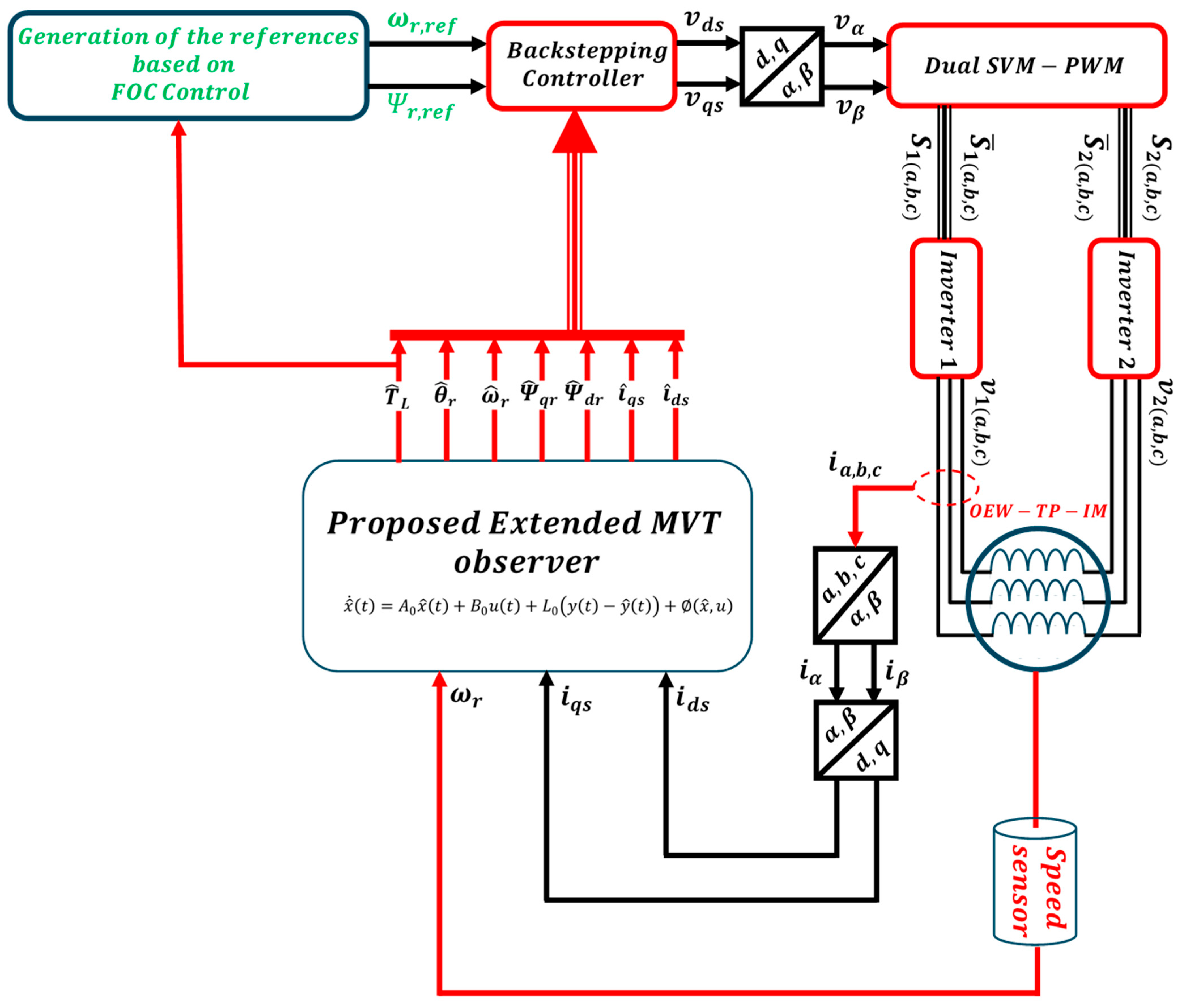
3. Backstepping Control Design Based on a MVT Observer

The control approach proposed in this paper aims to enhance the control of a nonlinear system represented by an OEW-TP-IM by combining the backstepping technique with the mean value theorem. Indeed, with the systematic and recursive properties of this proposed approach, it adeptly handles at the same time the parametric uncertainties and nonlinearities of the controlled motor. It worth clarifying that the introduction of the mean value theorem (MVT) ensures determining the matrix gains based on integrating the concept of a new extended observer. This developed approach transforms the dynamic equations of the observer state errors into suitable forms that allow establishing the stability criteria by solving the obtained linear matrix inequalities (LMIs) to ensure the use of the observer’s optimal gains.

3.1. Backstepping Control of OEW-IM Machine

Feedback control of nonlinear systems using the backstepping technique represents a very methodical and recursive design approach compared to other design concepts. It has been proven that taking into account parametric uncertainties and non-linearities by employing the backstepping technique during design can avoid unnecessary compensations, which provide multiple choices of design laws. The concept of the backstepping technique is based on an adequate choice of auxiliary or virtual functions depending on the state of the system, which will be considered as inputs for the lower-degree subsystem so that this subsystem is asymptotically stable based on the Lyapunov concept. Indeed, the designs for the next phase involve evaluating the remainder of the virtual controls that will be obtained after each previous design phase. The final phase includes the feedback control for the determination of the actual inputs to guarantee the main objective of initial design through a final choice of a Lyapunov function, which are brought together by the addition of all the elementary Lyapunov functions associated with each individual design. The nonlinear system design procedure is applied for a nonlinear system using Equation (1) in two steps.
In this study, the mechanical speed and the rotor flux were selected to be the first and the second output, respectively. These output are included in the control steps representing the main objectives of the overall control proposed approach:
  y x = h 1 x e h 2 x e = w r Ψ r e f

3.2. Speed and Flux Control

To ensure the control of the both outputs, namely the rotor speed and the rotor flux, the following steps have to be achieved.
Step 1
In the initial phase, the identification of the external loop errors is paramount to ensure accurate determination of the virtual controls. This involves selecting a suitable Lyapunov function, which enables dynamic control of the rotor speed and flux errors to asymptotically converge to zero. Typically, it is selected as a positive definite function, often quadratic in form. This approach allows building a fundamental framework for ensuring the stability and the accuracy of the control system performance by addressing the following errors:
e 1 = w r e f   ( t ) w ( t ) e 2 = Ψ r e f ( t ) Ψ r d t
The derivative of the error can be obtained as follows:
e 1 ˙ t = w ˙ r e f t n p   M J   L r   Ψ r d i s q f J w r + T L J e 2 ˙ t = ( Ψ ˙ r e f ( t ) M τ r   i s d + 1 τ r   Ψ r d )  
The first selected Lyapunov candidate function V 1 e 1 , e 2 , which is defined as positive, is expressed as
V 1 e 1 , e 2 = 1 / 2 ( e 1 2 + e 2 2 )
Based on Equation (6), its derivative can be obtained:
V ˙ 1 = e 1 w ˙ r e f t n p M J L r Ψ r d i s q f J w r + T L J + e 2 ( Ψ ˙ r e f ( t ) M τ r i s d + 1 τ r Ψ r d )
To ensure the asymptotic convergence of the errors towards zero in the closed-loop dynamic system, the reference currents should be chosen as follows:
i s q r e f = ( n p M J L r Ψ r d i s q ) 1 ( K 1 e 1 + w ˙ r e f t f J w r + T L J   ) i s d r e f = ( M τ r ) 1 ( Ψ ˙ r e f ( t ) + 1 τ r Ψ r d + K 2 e 2 )  
where the gains K 1 and K 2 are positive. Following this selection of the reference currents, Expression (6) can be rewritten accordingly:
e 1 ˙ t = K 1 e 1 e 2 ˙ t = K 2 e 2
Hence, the Lyapunov stability criterion is satisfied:
V ˙ 1 = K 1 e 1 2 K 2 e 2 2 0
So, the control of the currents i s q and i s d following the selected reference currents i s q r e f and i s d r e f presented in (9) allows ensuring the asymptotic stability based on the Lyapunov concept.
Step 2
The second step is dedicated to the accomplishment of the internal and final loop of current errors, which involves comparing the reference currents generated by the first loop with the actual current values. This comparison forms the basis for the required adjustment and control action to ensure that the real currents will accurately track their desired references, where the resulting difference can be expressed by the following errors:
e 3 t = i s q r e f i s q e 4 t = i s d r e f i s d
The second proposed Lyapunov candidate function, which takes into accounts the fourth error, is presented in (13), and it presents the overall final Lyapunov candidate function. This function is crucial for verifying the stability and effectiveness of the control system, as it demonstrates a decrease in the total system energy over time:
V 2 e 1 , e 2 , e 3 , e 4 = 1 / 2 ( e 1 2 + e 2 2 + e 3 2 + e 4 2 )
The derivative of V 2 ( e 1 , e 2 , e 3 , e 4 ) can be obtained:
V ˙ 2 = K 1 e 1 2 K 2 e 2 2 K 3 e 3 2 K 4 e 4 2 0
To ensure the Lyapunov asymptotic stability, the condition V ˙ 2 0 should be satisfied, which means that the control input should obey to the following expression:
U s d = σ L s ( i s d   r e f + K 3 e 3 δ 3 ) U s q = σ L s i s q   r e f + K 4 e 4 δ 4
where
δ 4 = γ i s q   w s i s d   k s   τ r   Ψ r d M   τ r i s d i s q   δ 3 = γ i s d   + w s i s d   + k s   τ r   Ψ r d M   τ r i s q i s q / Ψ r d
Additionally, the constants K 3 and K 4 must be positively defined and judiciously selected to ensure quick responsiveness in tracking the desired trajectories. These constants are crucial for achieving asymptotic convergence of current errors, even in case of parameter variations, load condition changes, and the occurrence of faults such as a single-phase short circuit within a closed-loop system.

4. Mean Value Theorem Observer Design

To design the extended observer with the augmented state x e t , a powerful method is presented for ensuring the accurate control of the following dynamic and nonlinear systems, which is based on the class of nonlinear systems described by the following nonlinear state equations system:
x e ˙ t = f e x e t + g e x e t u t y t = C x e t  
with
x e = i s d i s q Ψ r d Ψ r q ω r T L θ r T
y t = Ψ r q ω r T
where, in the present study, f e x e t : R 7 R 7 and g e x e t : R 7 x R 2 R 7 are nonlinear, and f e x e t is assumed to be differentiable.
Equation (17) can be further presented in the Lipschitzian form based on the model presented in [12,13]:
x e ˙ t = A 0 x e t + B 0 u t + x e t , u y = C x e t
where x e ( t ) R 7 is the state vector, u ( t ) R 2 is the input vector, and y ( t ) R 2 is the output vector. A 0 , B 0 , and C are constant matrices of appropriate dimensions. The matrices A 0 and B 0 are the nominal matrices, and
x e t , u = f e x e t A 0 x e t g e x e t = B 0
The state equation of the observer to be designed can be presented as follows:
x ^ ˙ t = A 0 x ^ t + B 0 u t + L 0 y t y ^ t + x ^ , u
Hence, the dynamics of the state estimation state that illustrates how the deviation from the actual state evolves is based on the error derivative as follows:
e ˙ t = A 0 L 0 C e ( t ) + ( x e t , u x ^ , u )
where
e t = x e t x ^ e t
The stability synthesis of the model presented in Equation (21) cannot be achieved directly in its current form. Therefore, the main focus in the following sub-section involves applying the mean value theorem and the concept of sector linearity to determine the appropriate matrix gain L 0 of Equation (20), which ensures the stability of the state estimation of Equation (21). This approach helps refine the stability analysis and enhance the effectiveness of the control system.

4.1. Mean Value Theorem

The concept of the mean value theorem, thoroughly detailed in references [12,13], will be utilized to determine the matrix gain of the estimator. Indeed, the dynamic equation of observer state error presented in (21) is transformed into a more suitable form based on the application of the mean value theorem as discussed deeply in [13]. This transformation is crucial for identifying the stability criteria in solving the linear matrix inequalities (LMIs), thereby allowing a clearer path for ensuring the stability of the system. To obtain the error global formulation, the following definition and proposition were used in this study.
Definition 1. 
Let us consider the nonlinear vector function  φ x :
φ x :   R n R n
where
φ x = φ 1 , φ 2 , φ 3 , . . φ n , with each component function  φ i : R n R
In addition, let us define a set  E r , consisting of canonical basis vectors in  R r , given by
E r = { e r i | e r i = 0 , , 0,1 , 0 , . . , 0 T ,   i = 1 , . r }
Using the definition of  φ x , the function can be rewritten in the form
φ x = j = 1 r e r i φ i ( x )
This definition is used in the following proposition.
Proposition 1. 
([12]). Let  φ : R n R n , and let  a , b R r . We assume that  φ  is differentiable on  C O ( a , b ) . Then, there are constant vectors  ξ 1 , ξ 2 , . . ξ i , ξ r C O ( a , b ) ,  ξ i a , and  ξ i b  for  i = 1 , . n  such that
φ a φ b = i = 1 n j = 1 n e n i e n j T φ i x j ξ i ( a b )
This proposition is applied to obtain the error global formulation used in this study as follows:
e ˙ t = A 0 L 0 C + i = 1 n j = 1 n e n i e n T j φ i x j ξ i e ( t )
As explained previously,  ξ i  is any convex combination of  x e t  and  x ^ e t  that can be expressed as  ξ i C O ( x e t , x ^ e t ) ; this means that  ξ i  lies on the line segment connecting  x e t  and  x ^ e t  for all  i = 1 , n e n i  is a vector of the canonical basis of the vectorial space  R n , and  e n T j  is the transpose vector of  e n i .

4.2. Nonlinear Sector Concept

At this stage, it is necessary to apply the nonlinear sector concept to transform the nonlinear terms in Equation (26) into a series of matrices. This approach allows a structural and analytical treatment of the nonlinearities, facilitating the application of linear control techniques to manage the system dynamics effectively.
Using nonlinear sector transformations, each nonlinearity φ i x j ξ j can be represented as
φ i x j ξ j = l = 1 2 w i j l ξ j a i j l
where
a i j 1 = a i j and a i j 2 = b i j ; l = 1,2 .
a i j and b i j are, respectively, the minimum and the maximum of φ i x j ξ j .
w i j 1 ξ j and w i j 2 ξ j are the activation functions based on the fuzzy model defined by T-S (Takagi–Sugeno). Hence, l = 1 2 w i j l ξ j = 1 , and 0 w i j l ξ j 1 .
By using this nonlinear sector transformation, the last term in (26) can be rewritten as follows:
i = 1 n j = 1 n e n i e n T j φ i x j ξ i = r = 1 r μ i ξ t A i *
Finally, from Equations (27) and (28) and the appropriate assumption on φ i , the dynamic state estimation error can be represented as
e ˙ t = r = 1 r μ i ξ t A 0 L 0 C + A i * e ( t )
where r 2 n 2 and ξ t x e t , x ^ ( t ) .

4.3. Stability Design

Based on the obtained equation of the state estimation error, the analyses of the stability can be carried out using the main criteria of the Lyapunov concept. To achieve this, an appropriate quadratic Lyapunov function is selected, which provides a systematic approach for determining whether the system maintains stability under various operating conditions; this function is expressed as follows:
V e t = e T t P e t   a n d   P = P T > 0
It is obvious from the stability theory that to ensure the stability of the system, the state estimation error has to converge asymptotically towards zero if there exists a matrix P = P T > 0 . As a result, the conditions of stability can be established through a theorem that is based on a specific matrix inequality, which is called linear matrix inequalities (LMIs). These LMIs must be satisfied to confirm the conditional stability of the system, thereby providing a robust framework for assessing and enhancing system performance:
A 0 T P + P A 0 + A i * T P + P A i * M C M T C T + α P < 0
For i = 1 , , r 2 n 2 , the matrix gain L 0 can be expressed as follows:
L 0 = P 1 M
The dynamic state estimation error is presented in Equation (29), where the matrices   A i * are derived from the following expression:
f e x ξ = γ f e 1 x 2 ( ξ ) k s τ r f e 1 x 4 ( ξ ) f e 1 x 5 ξ 0 0 f e 2 x 1 ( ξ ) f e 2 x 2 ( ξ ) f e 2 x 3 ( ξ ) k s τ r f e 2 x 5 ( ξ ) 0 0 M τ r f e 3 x 2 ( ξ ) 1 τ r f e 3 x 4 ( ξ ) 0 0 0 0 f e 4 x 2 ( ξ ) f e 4 x 3 ( ξ ) 1 τ r 0 0 0 f e 5 x 1 ( ξ ) f e 5 x 2 ( ξ ) f e 5 x 3 ( ξ ) f e 5 x 4 ( ξ ) f J 1 J 0 0 0 0 0 0 0 0 0 0 0 0 1 0 0
where
f e 1 x 2 ξ = n p . ξ 5 + 2 . k 1 . ξ 2 ; f e 1 x 4 ξ = f e 2 x 3 ξ = k s n p . ξ 5 ; f e 1 x 5 ξ = k s . n p . ξ 4 + n p . ξ 2 f e 2 x 1 ξ = n p . ξ 5 k 1 . ξ 2 ; f e 2 x 2 ξ = γ + k 2 f e 5 x 4 ξ = γ k 1 . ξ 1 f e 2 x 5 ξ = k s . n p . ξ 3 n p . ξ 1 ; f e 4 x 2 ξ = M τ r k 2 f e 5 x 2 ξ = M ( Ψ r d + 1 ) τ r Ψ r d . ξ 3 f e 3 x 4 ξ = f e 4 x 3 ξ = k 2 f e 5 x 3 ξ = k 1 . ξ 2 ; f e 3 x 2 ξ = k 2 f e 5 x 1 ξ = k 1 . ξ 4
Figure 2 illustrates the functional diagram of the control scheme, which presents the overall layout of the proposed control system through main blocks. These blocks include backstepping controllers that are designated to ensure two tasks: the first one manages the motor speed and flux, while the second one controls the currents. Additionally, the diagram incorporates an extended mean value theorem (MVT) observer, which is strategically placed in a feedback loop. This observer plays a crucial role in enhancing the accuracy and responsiveness of the control system by continuously monitoring and adjusting the system’s performance based on real-time feedback.

5. Simulation Results

The proposed backstepping control strategy, which incorporates an extended mean value theorem (MVT) observer as part of the global control scheme depicted in Figure 2, was implemented and evaluated through simulation in the MATLAB/Simulink environment. This advanced control technique was applied to an open-end winding three-phase induction machine (OEW-TP-IM) equipped with dual space vector modulation–pulse width modulation (SVM-PWM) parallel inverters operating under field-oriented control (FOC). This setup is specifically chosen for its ability to enhance the precision and efficiency of motor control.
The parameters of the OEW-TP-IM and its control system are critical for understanding its operation and the effectiveness of the backstepping control approach. These parameters, which typically include motor specifications like resistance, inductance, and rated power and inverter characteristics such as voltage and frequency ranges, play a significant role in determining the system’s performance under various load conditions and operational environments. Detailed simulation results from MATLAB/Simulink provide valuable insights into the obtained performance of the control strategy, specifically in managing the motor dynamics, including response time, stability, and error minimization, that are thoroughly analyzed, underscoring the effectiveness and robustness of the proposed approach. These outcomes highlight the potential improvements in motor control systems facilitated by integrating advanced observers and control methodologies based on the parameters presented in Table 1 [19].
The observer gain L 0 is determined from Equation (28) by solving a linear matrix inequality (LMI) problem to ensure the asymptotic stability of the extended mean value theorem (MVT) estimator. This is achieved using the YALMIP toolbox, a popular MATLAB tool for optimization and modelling of complex systems:
L 0 = 1.782 × 10 7 3.141 × 10 4 2.572 × 10 4 1.627 × 10 7 2.671 × 10 6 7.504 × 10 3 721.931 2.152 × 10 6 2.658 × 10 3 3.575 × 10 5 6.041 × 10 4 1.136 × 10 8 2.727 × 10 5 9.419 × 10 4

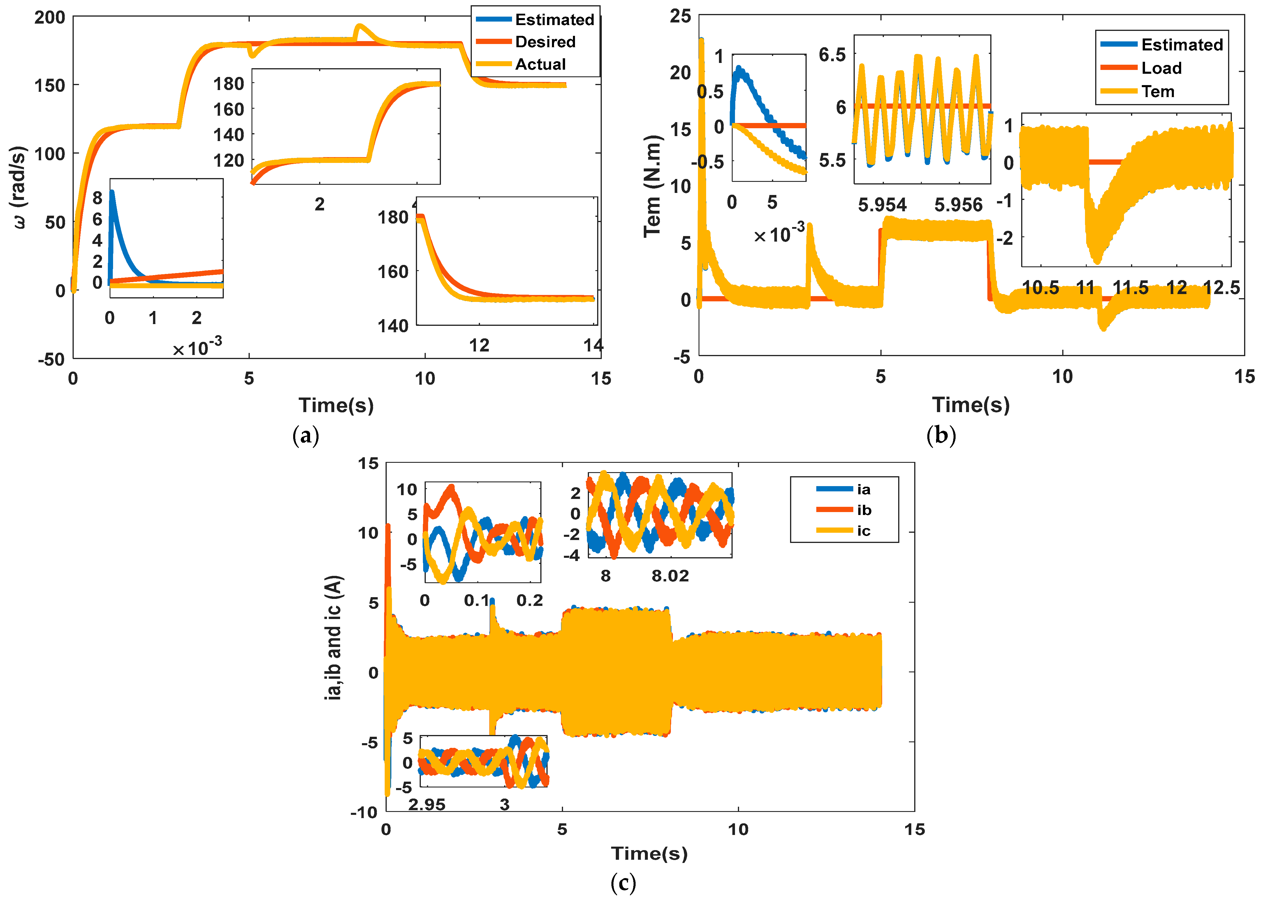
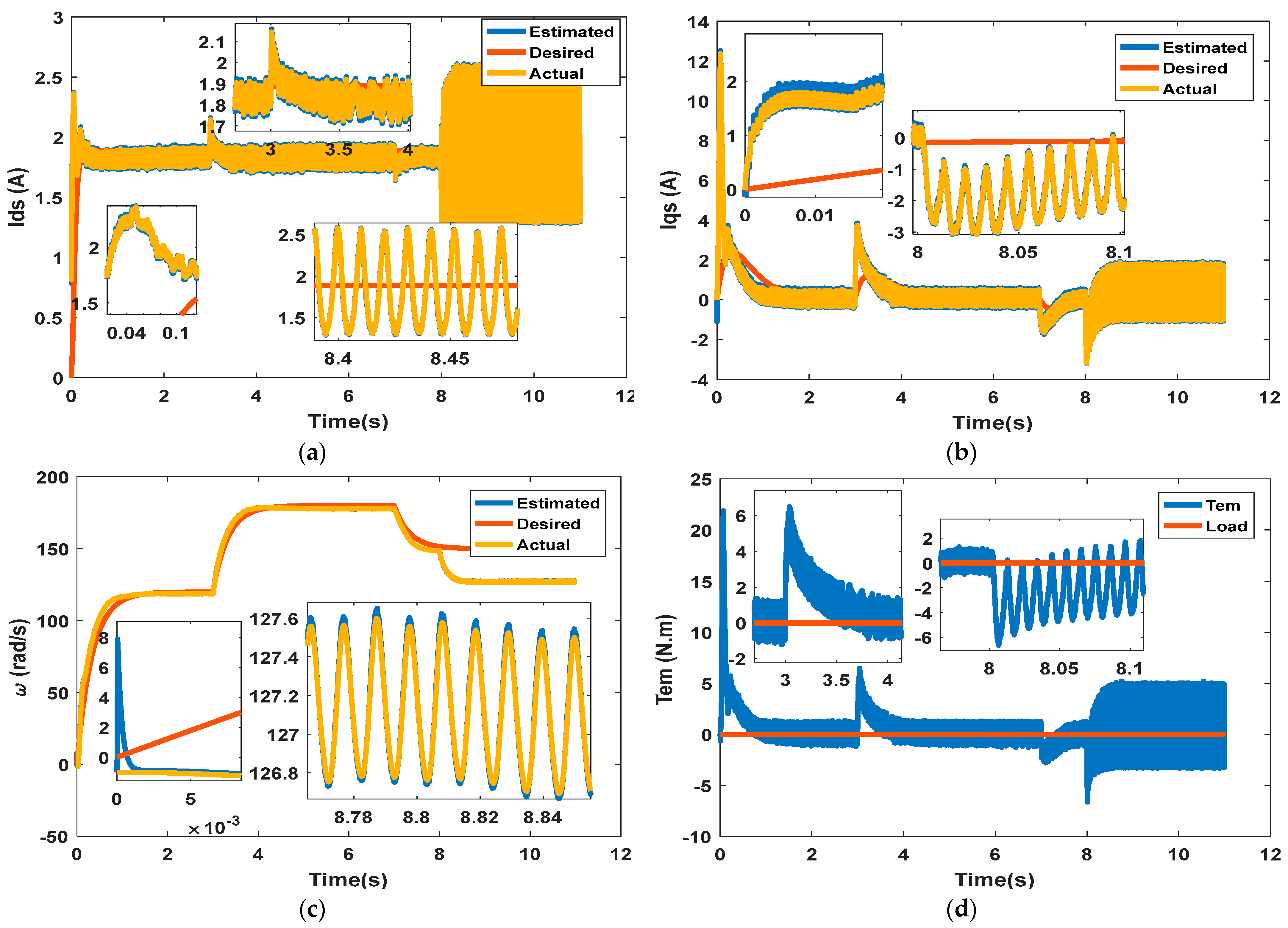
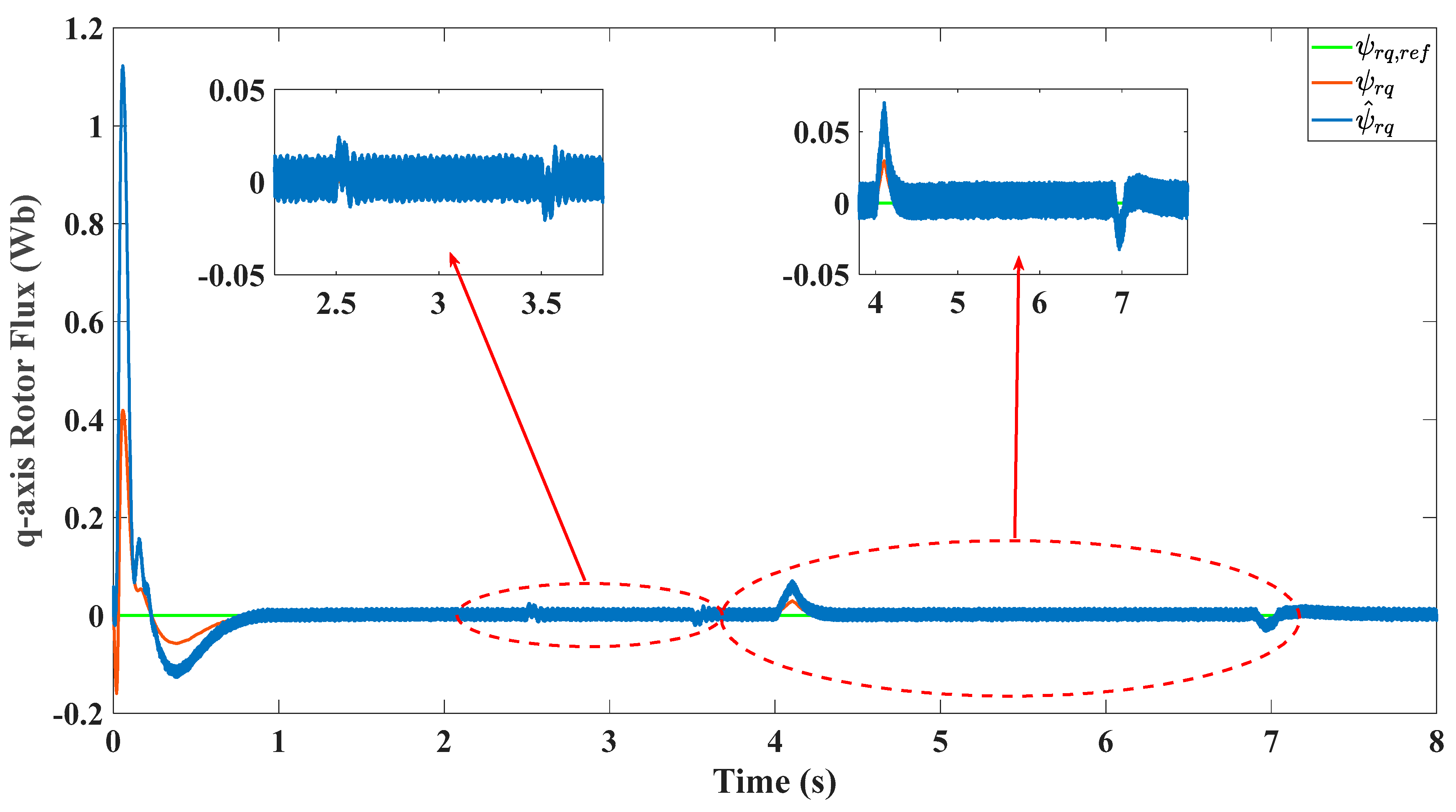
5.1. Assessment of Performance Under Normal Operating Conditions

The extended observer-based backstepping controller utilizing mean value theorem (MVT) is specifically engineered to achieve precise control over flux trajectories with targets set at Ψ r d = 0.854   W b and Ψ r q = 0   W b , as shown in Figure 3a,b. Additionally, it aims to particularly manage the rotor speed in tracking the desired profile, as shown in Figure 4a. Indeed, the obtained results depicted in Figure 3 and Figure 4 represent the desired, estimated, and actual dynamics of the rotor flux and the developed torque, clearly demonstrating the accuracy of the proposed control, which is confirmed also by the rotor state flux trajectory as shown in Figure 5.
Initially, the motor operates without a load until t = 5 s. Subsequently, a load ranging from 0 to 6 Nm is gradually applied until t = 8 s. A critical observation from these simulations is the remarkable alignment between the desired and actual speeds, as shown in Figure 4a, which showcases the controller’s capability to maintain a low error margin across varying operational conditions. The simulated results indicate a near-perfect superposition of estimated trajectories on the desired speed, highlighting the controller’s precision. The estimated speed by the observer tracks closely with the actual speed, following a particularly defined trajectory with minimal difference or error. During transient phases or when adjustments are made to reference speed, significant differences or errors are initially observed but rapidly diminish to near zero. In scenarios involving load adjustments, transient error peaks are noticeable but are resolved swiftly, underscoring the effectiveness of the implemented control strategies.
Furthermore, when compared with other studies, such as those cited in references [3,29], which explore various approaches to designing state observers, it is evident that the MVT observer significantly reduces errors, providing quick adaptations to transient conditions and delivering more accurate estimates. This comparison not only highlights the superior performance of the MVT observer in dynamic environments but also validates the robustness and precision of this advanced control system.

5.2. Performance Under Short Circuit and Parameter Variations

In comprehensive study, we examined the effects of a complete short circuit in the A-phase, occurring between t = 8 s and 11 s and under no load torque, where it is clear that within this range of time, the speed changes its value from 150 rad/s to 120 rad/s. Indeed, the backstepping algorithm controller using the MVT (mean value theorem) observer demonstrates robust control capabilities comparable to those in the healthy state, especially in tracking the reference speed, as shown in Figure 6a. It is obvious that the real, estimated, and desired states of speed show minor oscillations, which are negligible, amounting to less than 0.9%. Hence, their impact on the produced noise and mechanical vibrations are neglected. Upon the sudden onset of the fault, there are very small fluctuations in the electromagnetic torque with a ripples of 8 Nm (peak to peak); this leads to slightly unbalanced currents in each phase, rising from 2.2 A in normal conditions to 5.3 A in phases b and c and falling to 1.8 in phase a during the fault. This variation underscores the significant, effective role of the control system in maintaining efficient and reliable speed and flux regulation of the induction motor (IM) under field-oriented control (FOC) commands, as illustrated in Figure 7, with small fluctuations in the speed around 0.8 rd/s, 0.02 Wb in Q-rotor flux, and (+0.5 to −0.5 A) in both currents I d s and I q s . Moreover, throughout the simulation, both the estimated and actual speeds consistently track the desired speed despite the changes in predetermined trajectories and even at very low speeds. This demonstrates that the MVT observer, integrated with the backstepping controller, delivers high-performance results, maintaining desired references effectively even in the event of failures, where the error between the estimated speed and flux components and their current values is nearly negligible, leading to FOC decoupling control conditions and validating the overall effectiveness of the control strategy.
In the second simulation test, the effects of parameters variation and uncertainties on the performance and robustness of a system using mean value theorem (MVT) observer combined with a backstepping controller were investigated, as depicted in Figure 6 and Figure 7. This test aims to demonstrate the control design’s effectiveness by initially setting the stator’s nominal resistance at R s = 10.5 Ω from the starting time of 3.5 to 4.5 s. Subsequently, the resistance values of the induction motor (IM) are adjusted, ranging from R s to 1.4 R s , and the rotor resistance shifts from R r to 1.4 R r at the precise moment of t = 5 s until 6.5 s, intentionally overlooking the thermal effects on the machine’s parameters.
Figure 6 and Figure 7 display the estimated flux and speed of the rotor for this scenario, replicating previous tests using identical speed references. The results indicate a substantial reduction in the estimation error between the actual and estimated speeds, showcasing the precise dynamic capabilities of the speed controller and estimator.
Additionally, the backstepping control mechanism effectively maintains the rotor flux close to its desired value, demonstrating resilience against resistance variations within the IM motor, as shown in Figure 7b. These results closely align with those previously observed in Figure 6, confirming that the system’s stability remains intact even with 40% variations in Rs and Rr occurring at different times. This stability is attributable to the adeptly chosen control strategy that robustly counters these adverse operational conditions.
This obtained stability is due to the effectiveness of the selected combined control strategy, which effectively mitigates the unfavorable operating conditions.
The impressive performance characteristics observed with this control technique on the open-winding three-phase induction motor (TP-IM) encourage its application across a range of industrial processes. By adopting this control setup, it is possible to address and surmount common challenges faced in practical applications, offering superior performance and operational advantages over other existing techniques. This makes the system particularly valuable for enhancing reliability and efficiency in industrial settings where parameter fluctuations are commonplace.

5.3. Performance Metrics Evaluation of the Proposed Extended MVT Observer

In this sub-section, only two cases were taken for the demonstration of the performance merits of the proposed combined controller based on extended MVT observer, such as the speed dynamics and the q-axis rotor flux dynamics under severe conditions, such as internal and external disturbances, as follows:
  • Variation of R s by 30% of its initial value, which is considered an internal parameter uncertainty;
  • Load torque T L variation, which is considered an external perturbation.
In this analysis, the main aim is to evaluate the dynamic tracking performance and the robustness performance of the proposed approach based on metric indicators.
The first analysis involves the computation of the errors between the reference speed w r e f = 180   red / s and the two speeds, namely the actual speed w r obtained based on the proposed combined control and the estimated speed w ^ r obtained from the proposed extended MVT observer. These two errors are expressed, respectively, as follows:
e 1 = w r w r e f e 2 = w ^ r w r e f
Indeed, based on these errors, it is possible to evaluate the transient response metrics (rise time, settling time, and overshoot) for the speed dynamic and the global performance metrics for tracking both speeds. The performance metrics that are also used for the assessment of the q-axis rotor flux include:
  • RMSE: root mean square error;
  • IAE: integral of absolute error;
  • ITAE: integral of time-weighted absolute error;
  • ISE: integral of squared error.
The three speeds are shown in Figure 8, namely as the desired speed w r e f , the actual speed w r , and the estimated speed w ^ r . It is clear from the increase of the transient response at start-up that the actual speed and the estimated speed track nearly in the same way as the reference speed.
Based on Table 2, which presents the transient response metrics for the actual rotor speed w r and the estimated rotor speed w ^ r , it can be said that that the proposed extended MVT observer provides accurate estimation of the system dynamics. The rise time for the estimated speed is slightly higher (0.2698 s) compared to the actual value (0.2461 s), which indicates a minimal delay in reaching the desired or reference speed. Similarly, the settling time of the estimated speed (2.6271 s) remains close to that of the actual speed (2.5164 s), which proves the capability of the proposed observer to accurately track the desired speed dynamic behavior with less mismatch. On the other side, the overshoot is nearly identical for both speeds: the actual and estimated speeds have values of 7.5142% and 7.4145%, respectively. This confirms that the proposed extended MVT observer guarantees the transient characteristics of the controlled open-end winding induction motor. These obtained results confirm the effectiveness of the proposed observer in issuing accurate estimations of the variables that are close to the real system variables, and hence, this proposed observer can be suitable for robust and accurate speed and rotor flux estimation of the motor under study.
On the other hand, the two increases are depicted in Figure 8, presenting the two speeds w r and w ^ r during the intervals [2.5–3.5 s] and [3.8–7.8 s], respectively. The first interval is related to the occurrence of the stator resistance variation R s , and the second interval is related to the occurrence of the load torque variation T L .
The performance metrics of the actual and estimated speeds for both intervals are calculated and presented in Table 3. It can be seen that the proposed combined nonlinear controller demonstrates favorable accuracy and robustness in tracking the reference speed and the actual speed. It is also noted that the internal disturbance related to R s does not have any influence on the dynamics of the estimated speed and the actual speed, which confirms the robustness of the proposed control and the proposed extended MVT observer. Although the transient response is relatively slower under external disturbance, as shown in the interval [3.8–7.8 s], the global error performance metrics are very acceptable, indicating the precise tracking capabilities of the proposed observer. Indeed, the lower RMSE proves the accuracy of the observer: a lower IAE means the observer consistently maintains a small error, a lower ISE implies improved robustness and control quality, and a lower ITAE indicates fast deviation correctness and stability capabilities.
In this analysis, the robustness performances were evaluated further under the presence of the external disturbances presented by the load torque variation T L . This anlysis of the performance metrics is based on the errors recorded between the reference rotor flux ( Ψ r q , r e f = 0 ) and the two fluxes: the actual rotor flux Ψ r q and the estimated rotor flux Ψ ^ r q obtained from the proposed extended MVT observer. It is worth clarifying that only the global performance metrics (RMSE, IAE, ITAE, and ISE) were considered for both errors. The first error and the second error are denoted, respectively, by e Ψ r q 1 and e Ψ r q 2 and expressed as follows:
e Ψ r q 1 = Ψ r q Ψ r q , r e f = Ψ r q e Ψ r q 2 = Ψ ^ r q Ψ r q , r e f = Ψ ^ r q
The obtained global performance metrics are presented in Table 4, and they are based on the results presented in Figure 9.
From Figure 9, it can be observed that the estimated rotor flux Ψ ^ r q shows perfect alignment with the actual flux Ψ r q under internal parameter uncertainty and external distrbance. On the other hand, all the adopted metrics, such as RMSE, IAE, ISE, and ITAE, for the estimated rotor flux Ψ ^ r q confirm superior alignment compared to the actual rotor flux Ψ r q , as shown in Table 4, which indicates the excellent estimation accuracy and robustness of the designed observer and confirms the neglected sensitivity to parameter variation (stator resistance) and external perturbation (load torque).
Furthermore, from Figure 5, it can be noted that the estimated speed is aligned with the estimated speed w ^ r in tracking the desired speed within the steady-state regions. Indeed, Table 5 records a bit of difference between the performance metrics corresponding from one side to the estimated speed w ^ r compared to the actual speed w r and on the other side between the estimated q-axis rotor flux and the actual q-axis rotor flux. This outcome is both expected and reasonable due to the fundamental nature of observer-based control systems, which is inherently affected by the assumption taken into consideration, leading to model uncertainty while modeling the open-end winding induction motor, where in fact the R s is affected by this assumption, which is considered an internal parameter. However, its impact is very minimal, as can be clearly noted in Figure 8.
It is worth clarifying that the design of the proposed extended MVT observer is optimized for robustness and convergence rather than exact matching at every instant of the actual value within the acceptable range, which does not affect the dynamic control. This trade-off ensures that even under degrading conditions, the estimated speed converges closely to the actual value, albeit with slight difference in the error metrics. On the other side, the proposed observer under examination is an inherent internal part of the control loop to ensure the control objective, which is achieved similarly to the actual motor speed. Hence, the enhanced performance metrics on the actual speed demonstrate the effectiveness of the control strategy in achieving its goal. Furthermore, the observed difference, though slightly lower, remains within acceptable range and does not degrade overall control stability or accuracy.
Indeed, the overall performance metrics under load torque variation and stator resistance variation show consistency and convergence of the observer, where the recorded values of the fourth metrics are acceptable, clearly confirming that the proposed observer is robust against internal and external constraints. It is reasonable to say that the metric indicators of observed speed and flux remain within a controlled range, where the presented results demonstrate that the proposed nonlinear observer provides better accuracy in both flux and speed estimation, maintains dynamic performance under internal parameter variation and external perturbation, preserves the effectiveness of vector control by maintaining the rotor flux orientation, and outperforms other existing conventional approaches under lower global performance metrics of the errors recorded for the rotor flux and developed speed. These outcomes clearly confirm the superiority and reliability of the proposed extended MVT observer in ensuring the control of the three-phase open-end winding induction motor in practical applications facing internal parameter uncertainty and external perturbations.

5.4. Discussion

The analysis of the simulated results reveals that the performance characteristics for estimating rotor fluxes in quadrature (zero for the d-axis and 0.85 for the q-axis) and rotation speed reach nominal values, aligning well with the desired speeds. This control technique ensures good decoupling for field-oriented control (FOC) across different desired rotation speeds, from high to medium levels.
Notably, the load and developed torque exhibit precise continuity in tracking the form of the applied torque, and the phase currents approach sinusoidal forms with low approximate ripple rates, with a maximum value of 0.25 A even across a varying speed profile. The estimation errors remain very low and quickly become negligible in steady-state conditions.
The obtained results demonstrate the excellent performance of the MVT observer based on a backstepping controller for the complex nonlinear system of an induction motor (IM) powered by dual SVM-PWM inverters. It can be said that with the accelerated development of modern microprocessors, digital calculation is required in controllers, and estimation algorithms must be very fast and cost-effective, making the implementation of this MVT observer easier compared to other approaches, where only the numerical values calculated offline need to be introduced to the processors. Furthermore, for electrical machines, fault diagnosis and fault-tolerant control techniques are hot topics in the research community [38,39,40]. Power electronics also play a critical role in the electric motor drive systems [41,42,43].

6. Conclusions

The study presents the concept of sensorless backstepping control applied to the OEW-TP-IM motor drive. This innovative control scheme employs an MVT (mean value theorem) nonlinear observer using a nonlinear sector approach to estimate the states of the OEW-TP-IM machine, which is powered by dual SVM-PWM inverters operating under field-oriented control (FOC).
The implementation of the MVT observer-based backstepping controller in the MATLAB/Simulink environment demonstrated remarkable robustness against various parameter variations, uncertainties, and even a complete one-phase short circuit. The simulated results underscore the performance and efficiency of the proposed backstepping control when associated with an extended observer.
A critical objective of this research was to ensure the accurate tracking and convergence of both states—the estimated speed and q-flux error—towards zero. This accomplishment signifies a successful decoupling of rotor flux components from low to high programmed speed trajectories in FOC control. To mitigate the influence of load variations, the estimation of the load torque was integrally included in the overall control scheme. This inclusion is essential for backstepping control computation, ensuring accurate tracking and maintaining precise load torque values consistently.
Moreover, the system’s robustness was confirmed under various degrading operating conditions, including complete short circuits and parameter variations. The results demonstrated successful speed tracking and maintained decoupling between flux and torque, showcasing the control strategy’s resilience and adaptability.
The next step involves implementing and testing the control and estimation algorithms using modern microprocessor chips, which are both affordable and readily available. This practical validation will further solidify the theoretical findings and demonstrate the real-world applicability of the proposed control scheme.
In conclusion, the advantages of this control strategy make it a promising candidate for complex industrial drive applications that demand precise and accurate tracking of speed and flux. The sensorless backstepping control, combined with the MVT observer, presents a robust and efficient solution, ensuring high performance even under challenging conditions. The integration of modern microprocessors will enhance the feasibility and scalability of this approach, making it a viable option for a wide range of industrial applications.

Author Contributions

Conceptualization, O.A., A.K. and M.A. (Meriem Allag); methodology, O.A., A.K., M.A. (Meriem Allag), A.H., J.R. and M.A. (Meriem Allag); software, O.A. and M.A. (Meriem Allag); validation, O.A., A.K., M.A. (Meriem Allag) and A.H.; formal analysis, O.A., A.K., M.A. (Meriem Allag) and M.A. (Mohamed Abdelrahem); investigation, O.A., A.K. and M.A. (Meriem Allag); resources, A.K., A.H., J.R. and M.A. (Mohamed Abdelrahem); data curation, O.A., A.K. and M.A. (Meriem Allag); writing—original draft preparation, O.A., A.K., M.A. (Meriem Allag), A.H., J.R. and M.A. (Mohamed Abdelrahem); writing—review and editing, A.K., J.R. and M.A. (Mohamed Abdelrahem); visualization, O.A., A.K., M.A. (Meriem Allag) and A.H., supervision, A.K., J.R. and M.A. (Mohamed Abdelrahem); project administration, A.K., M.A. (Mohamed Abdelrahem) and J.R.; funding acquisition, M.A. (Mohamed Abdelrahem) and J.R. All authors have read and agreed to the published version of the manuscript.

Funding

J. Rodriguez acknowledges the support provided by ANID through projects FB0008, 1210208, and 1221293.

Data Availability Statement

All data used in this study are provided within the paper and its referenced sources.

Conflicts of Interest

The authors declare no conflicts of interest.

References

  1. Mavila, P.C.; Rajeevan, P.P. A New Direct Torque Control Scheme for Five Phase Open-end Winding Induction Motor Drives with Reduced DC Voltage Requirement. In Proceedings of the IEEE International Conference on Power Electronics, Smart Grid and Renewable Energy, Cochin, India, 2–4 January 2020. [Google Scholar]
  2. Levi, E.; Nyoman, I.; Wahyu, N.; Nandor, B.; Martin, J. A Space-Vector Modulation Scheme for Multilevel Open-End Winding Five-Phase Drives. IEEE Trans. Energy Convers. 2012, 27, 1–10. [Google Scholar]
  3. Trabelsi, R.; Khedher, A.; Mimouni, F.M.; M’Sahli, F. An Adaptive Backstepping Observer for On-Line Rotor Resistance Adaptation. Int. J. Sci. Tech. Autom. Control Comput. Eng. 2010, 4, 1246–1267. [Google Scholar]
  4. Moutchou, M.; Abbou, A.; Mahmoudi, H. MRAS-Based Sensorless Speed Backstepping Control for Induction Machine, Using a Flux Sliding Mode Observer. Turk. J. Electr. Eng. Comput. Sci. 2015, 23, 187–200. [Google Scholar] [CrossRef]
  5. Regaya, C.B.; Farhani, F.; Zaafouri, A.; Chaari, A. An Adaptive Sliding-Mode Speed Observer for Induction Motor under Backstepping Control. ICIC Express Lett. 2017, 11, 763–771. [Google Scholar]
  6. Zhonggang, Y.; Guoyin, L.; Yanqing, Z.; Jing, L.; Xiangdong, S.; Yanru, Z. A Speed and Flux Observer of Induction Motor Based on Extended Kalman Filter and Markov Chain. IEEE Trans. Power Electron. 2017, 32, 7096–7117. [Google Scholar]
  7. Khadar, S.; Kouzou, A.; Hafaifa, A.; Iqbal, A. Investigation on SVM Backstepping Sensorless Control of Five-Phase Open-End Winding Induction Motor Based on Model Reference Adaptive System and Parameter Estimation. Eng. Sci. Technol. Int. J. 2019, 22, 1013–1026. [Google Scholar]
  8. Khadar, S.; Kouzou, A.; Rezaoui, M.M.; Hafaifa, A. Fault Tolerant Sensorless Sliding Mode Control by Parameters Estimation of an Open-End Winding Five-Phase Induction Motor. Model. Meas. Control A 2019, 92, 6–15. [Google Scholar] [CrossRef]
  9. Khadar, S.; Abu-Rub, H.; Kouzou, A. Sensorless Field-Oriented Control for Open-End Winding Five-Phase Induction Motor with Parameters Estimation. IEEE Open J. Ind. Electron. Soc. 2021, 2, 266–279. [Google Scholar] [CrossRef]
  10. Meziane, S.; Toufouti, R.; Benalla, H. Nonlinear Control of Induction Machines Using an Extended Kalman Filter. Acta Polytech. Hung. 2008, 5, 41–58. [Google Scholar]
  11. Pourgholi, M.; Majd, V.J. A Nonlinear Adaptive Resilient Observer Design for a Class of Lipschitz Systems Using LMI. Circ. Syst. Signal Process 2011, 30, 1401–1415. [Google Scholar] [CrossRef]
  12. Zemouche, A.; Boutayeb, M.; Bara, G.I. Observer Design for Nonlinear Systems: An Approach Based on the Differential Mean Value Theorem. In Proceedings of the IEEE Conference on Decision and Control, Cancun, Mexico, 9–11 December 2008; pp. 6353–6358. [Google Scholar]
  13. Hammoudi, M.Y.; Allag, A.; Becherif, M.; Benbouzid, M.; Alloui, H. Observer Design for Induction Motor: An Approach Based on the Mean Value Theorem. Front. Energy 2014, 8, 426–433. [Google Scholar] [CrossRef]
  14. Imen, H.B.; Hajji, S.; Chaari, A. Backstepping Controller Design Using a High Gain Observer for Induction Motor. Int. J. Comput. Appl. 2011, 23, 1–6. [Google Scholar]
  15. Regaya, C.B.; Farhani, F.; Zaafouri, A.; Chaari, A. A Novel Adaptive Control Method for Induction Motor Based on Backstepping Approach Using dSpace DS1104 Control Board. Mech. Syst. Signal Process 2018, 100, 466–481. [Google Scholar]
  16. Bennassar, A.; Abbou, A.; Akherraz, M.; Barara, M. Sensorless Backstepping Control Using an Adaptive Luenberger Observer with Three Levels NPC Inverter. Int. J. Comput. Electr. Autom. Control Inf. Eng. 2013, 7, 1171–1177. [Google Scholar]
  17. Aziz, A.G.M.A.; Rez, H.; Diab, A.A.Z. Robust Sensorless Model-Predictive Torque Flux Control for High-Performance Induction Motor Drives. Mathematics 2021, 9, 403. [Google Scholar] [CrossRef]
  18. Zeghib, O.; Allag, A.; Allag, M.; Hamidani, B. A Robust Extended H∞ Observer Based on the Mean Value Theorem Designed for Induction Motor Drives. Int. J. Syst. Assur. Eng. Manag. 2019, 10, 533–542. [Google Scholar] [CrossRef]
  19. Allag, M.; Allag, A.; Zeghib, O.; Hamidani, B. Robust H∞ Control Based on the Mean Value Theorem for Induction Motor Drive. J. Control Autom. Electr. Syst. 2019, 30, 657–665. [Google Scholar] [CrossRef]
  20. Hamidatou, T.; Kouzou, A.; Kaddouri, A.M.; Mida, A. Fuzzy logic based speed control of indirect field oriented controlled doubly star open-end winding induction motor. In Proceedings of the 2023 Second International Conference on Energy Transition and Security (ICETS), Adrar, Algeria, 12–14 December 2023; pp. 1–6. [Google Scholar]
  21. Guzmán, J.; Silva, C.A.; Carvajal, G.; Agüero, J.C. Model Predictive Control for Suppression of Zero-Sequence Current in Open-End Winding Induction Motors. In Proceedings of the 2023 IEEE International Future Energy Electronics Conference (IFEEC), Sydney, Australia, 20–23 November 2023; pp. 251–256. [Google Scholar]
  22. Lee, K.; Han, Y. Discontinuous PWM Scheme for an Open-end Winding Induction Motor Drives Fed by Dual Inverter. In Proceedings of the 2022 IEEE Energy Conversion Congress and Exposition (ECCE), Detroit, MI, USA, 9–13 October 2022; pp. 1–6. [Google Scholar]
  23. Khadar, S.; Kouzou, A.; Mohamed-Seghir, M. “Stability Analysis of Adaptive Full-Order Observer for Open-End Winding Five-Phase Induction Motor. In Proceedings of the 2021 IEEE Southern Power Electronics Conference (SPEC), Kigali, Rwanda, 6–9 December 2021; pp. 1–5. [Google Scholar]
  24. Khadar, S.; Abu-Rub, H.; Kouzou, A. MRAS-Based Sensorless Control Scheme for Open- End Stator Winding Six-Phase Induction Motor with Fuzzy Logic Speed Controller: Real-Time Simulation. In Proceedings of the 2021 IEEE 30th International Symposium on Industrial Electronics (ISIE), Kyoto, Japan, 20–23 June 2021; pp. 1–6. [Google Scholar]
  25. Khadar, S.; Abu-Rub, H.; Kouzou, A. Sensorless Sliding Mode Control of Open-End Dual-Stator Induction Motor using Extended Kalman Filter. In Proceedings of the 2021 18th International Multi-Conference on Systems, Signals Devices (SSD), Monastir, Tunisia, 22–25 March 2021; pp. 1136–1141. [Google Scholar]
  26. Mohan, L.; Pant, K.; Rajeevan, P.P. A Speed Range Extension Scheme for Scalar-Controlled Open-End Winding Induction Motor Drives. IEEE Trans. Ind. Appl. 2022, 58, 2055–2062. [Google Scholar] [CrossRef]
  27. Jia, Y.F.; Xu, N.; Chu, L.; Zhang, Y.; Xu, Z.; Li, Y.K.; Yang, Z.H. Control Strategy for an Open-End Winding Induction Motor Drive System for Dual-Power Electric Vehicles. IEEE Access 2020, 8, 8844–8860. [Google Scholar] [CrossRef]
  28. Younes, D.; El Mehdi, A.S.A.; Houcine, C.; Mouloud, D. Sensorless Torque Control of an Electric Vehicle Driven by an Open End Winding Induction Motor: An Experimental Study. In Proceedings of the 2023 Second International Conference on Energy Transition and Security (ICETS), Adrar, Algeria, 12–14 December 2023. [Google Scholar]
  29. Lodi, K.A.; Beig, A.R.; Al Jaafari, K.A.; Aung, Z. ANN-Based Improved Direct Torque Control of Open-End Winding Induction Motor. IEEE Trans. Ind. Electron. 2024, 71, 12030–12040. [Google Scholar] [CrossRef]
  30. Reddy, K.S.; Baskar, S. A Literature Review on Open End Windings Induction Motor Drives. In Proceedings of the 2021 5th International Conference on Electrical, Electronics, Communication, Computer Technologies and Optimization Techniques (ICEECCOT), Mysuru, India, 10–11 December 2021; pp. 395–398. [Google Scholar]
  31. Hamdi, W.; Hammoudi, M.Y.; Boukhlouf, A. Observer Design for Takagi–Sugeno Fuzzy Systems with Unmeasurable Premise Variables Based on Differential Mean Value Theorem. Eng. Proc. 2023, 58, 28. [Google Scholar] [CrossRef]
  32. Houili, R.; Hammoudi, M.Y.; Benbouzid, M.; Titaouine, A. Observer-Based Controller Using Line Integral Lyapunov Fuzzy Function for TS Fuzzy Systems: Application to Induction Motors. Machines 2023, 11, 374. [Google Scholar] [CrossRef]
  33. Krzemiński, Z. Nonlinear Control of Induction Motor. IFAC Proc. Vol. 1987, 20, 357–362. [Google Scholar] [CrossRef]
  34. Ranjit, M.; Reddy, T.B.; Suryakalavathi, M. Performance Improvements in Open End Winding Induction Motor Drive Using Decoupled PWM Techniques. Energy Procedia 2017, 117, 810–817. [Google Scholar] [CrossRef]
  35. Zerdani, M.; Chafouk, H.; Ardjoun, S.A.E.M. Performance Analysis of a Dual-Inverter-Fed Open-End Winding Induction Machine under Asymmetrical Control: Theoretical Approach and Experimental Validation. Symmetry 2024, 16, 395. [Google Scholar] [CrossRef]
  36. Kiadehi, A.D.; Drissi, K.E.K.; Pasquier, C. Voltage THD Reduction for Dual-Inverter Fed Open-End Load With Isolated DC Sources. IEEE Trans. Ind. Electron. 2017, 64, 2102–2111. [Google Scholar] [CrossRef]
  37. Kalaiselvi, J.; Srinivas, S. Bearing Currents and Shaft Voltage Reduction in Dual-Inverter-Fed Open-End Winding Induction Motor with Reduced CMV PWM Methods. IEEE Trans. Ind. Electron. 2015, 62, 144–152. [Google Scholar] [CrossRef]
  38. Hang, J.; Wang, X.; Li, W.; Ding, S. Interturn Short-Circuit Fault Diagnosis and Fault-Tolerant Control of DTP-PMSM Based on Subspace Current Residuals. IEEE Trans. Power Electron. 2025, 40, 3395–3404. [Google Scholar] [CrossRef]
  39. Hang, J.; Qiu, G.; Hao, M.; Ding, S. Improved Fault Diagnosis Method for Permanent Magnet Synchronous Machine System Based on Lightweight Multisource Information Data Layer Fusion. IEEE Trans. Power Electron. 2024, 39, 13808–13817. [Google Scholar] [CrossRef]
  40. He, W.; Hang, J.; Ding, S.; Sun, L.; Hua, W. Robust Diagnosis of Partial Demagnetization Fault in PMSMs Using Radial Air-Gap Flux Density Under Complex Working Conditions. IEEE Trans. Ind. Electron. 2024, 71, 12001–12010. [Google Scholar] [CrossRef]
  41. Zeng, Z.; Zhu, C.; Goetz, S.M. Fault-Tolerant Multiparallel Three-Phase Two-Level Converters with Adaptive Hardware Reconfiguration. IEEE Trans. Power Electron. 2024, 39, 3925–3930. [Google Scholar] [CrossRef]
  42. Zhang, R.; Wang, S.; Ma, J.; Jiang, Y.; Wang, P.; Liu, T.; Yang, Y. An Asymmetric Hybrid Phase-Leg Modular Multilevel Converter with Small Volume, Low Cost, and DC Fault-Blocking Capability. IEEE Trans. Power Electron. 2025, 40, 5336–5351. [Google Scholar] [CrossRef]
  43. Li, S.; Zhou, J.; Zhou, F.; Niu, F.; Deng, W. A Reduced Current Ripple Overmodulation Strategy for Indirect Matrix Converter. IEEE Trans. Ind. Electron. 2025, 72, 3768–3777. [Google Scholar] [CrossRef]
Figure 1. Dual SVM-PWM Inverters Powering OEW-TP-IM Configuration.
Machines 13 00520 g001
Figure 2. FOC Implementation on OEW-TP-IM Using Dual SVM-PWM Inverters and MVT-Based Backstepping Controller Scheme.
Machines 13 00520 g002
Figure 3. The d and q axis rotor flux under torque variations: (a) d-Rotor Flux; (b) q-Rotor Flux.
Machines 13 00520 g003
Figure 4. Normal Operating Conditions Under Torque and speed Variations: (a) Rotor Speed; (b) Torque; (c) Currents.
Machines 13 00520 g004
Figure 5. Normal Operating Conditions Under Torque and speed Variations: (a) I d s current; (b) I q s current; (c) SVM-PWM Switching Times.
Machines 13 00520 g005
Figure 6. Short-Circuit Test and Parameter Variations (Rs and Rr with 40%): (a) Line Currents; (b) q-Axis Rotor Flux.
Machines 13 00520 g006
Figure 7. Short-Circuit Test and Parameter Variations (Rs and Rr with 40%): (a) I d s current; (b)   I q s current; (c) Speed; (d) Torque.
Machines 13 00520 g007
Figure 8. The actual speed tracking and the estimated speed under the proposed control.
Machines 13 00520 g008
Figure 9. The rotor flux tracking following q-axis under the proposed control.
Machines 13 00520 g009
Table 1. The paymasters of the Induction Machine under study.
ParametersSymbolValuesUnit
Pole pair numbernp2-
Rotor inductanceLr0.4718H
Stator inductanceLs0.4718H
Rotor resistanceRr4.30Ω
Stator resistanceRs10.5Ω
Mutual inductanceM0.4475H
Moment of inertiaJ0.0293Kg·m−2
Table 2. Speed transient response metrics.
w r w ^ r
Rise Time (s)0.24610.2698
Settling Time (s)2.51642.6271
Overshoot (%)7.51427.4145
Table 3. The performance metrics of the actual speed and the estimated speed under internal and external disturbances.
IntervalParameter R M S E I A E I T A E I S E
w r 2.5–3.5 s R s variation 1.10331.01733.05671.2172
3.8–7.8 s T L variation2.29256.344837.43121.242
w ^ r 2.5–3.5 s R s variation 1.30611.23983.72411.7059
3.8–7.8 s T L variation2.31426.948341.24721.423
Table 4. The performance metrics of the actual and the estimated q-axis rotor fluxes under internal and external disturbances.
IntervalParameter R M S E I A E I T A E I S E
Ψ r q 2.5–3.5 s R s variation 0.000960.00080.00249.19 × 10−7
3.8–7.8 s T L variation0.00450.00820.04440.00008
Ψ ^ r q 2.5–3.5 s R s variation 0.0060.0050.01493.56 × 10−5
3.8–7.8 s T L variation0.01050.026690.14760.00043
Table 5. Speed and rotor flux performance metrics under steady state.
R M S E I A E I T A E I S E
w r 1.0861.0015.51371.1794
w ^ r 1.28791.22256.73221.1794
Ψ r q 0.000920.000770.00443.04 × 10−5
Ψ ^ r q 0.00550.00470.0268.4 × 10−7
Disclaimer/Publisher’s Note: The statements, opinions and data contained in all publications are solely those of the individual author(s) and contributor(s) and not of MDPI and/or the editor(s). MDPI and/or the editor(s) disclaim responsibility for any injury to people or property resulting from any ideas, methods, instructions or products referred to in the content.

