Review

Current Status and Trends of Wall-Climbing Robots Research

by
Shengjie Lou
1,
Zhong Wei
1,*,
Jinlin Guo
1,
Yu Ding
1,
Jia Liu
1 and
Aiguo Song
2
1
The School of Automation, Nanjing University of Information Science and Technology, Nanjing 210096, China
2
The School of Instrumentation Science and Engineering, Southeast University, Nanjing 210096, China
*
Author to whom correspondence should be addressed.
Machines 2025, 13(6), 521; https://doi.org/10.3390/machines13060521
Submission received: 9 May 2025 / Revised: 12 June 2025 / Accepted: 13 June 2025 / Published: 15 June 2025
(This article belongs to the Section Robotics, Mechatronics and Intelligent Machines)

Abstract

:
A wall-climbing robot is an electromechanical device capable of autonomous or semi-autonomous movement on intricate vertical surfaces (e.g., walls, glass facades, pipelines, ceilings, etc.), typically incorporating sensing and adaptive control systems to enhance task performance. It is designed to perform tasks such as inspection, cleaning, maintenance, and rescue while maintaining stable adhesion to the surface. Its applications span various sectors, including industrial maintenance, marine engineering, and aerospace manufacturing. This paper provides a systematic review of the physical principles and scalability of various attachment methods used in wall-climbing robots, with a focus on the applicability and limitations of different attachment mechanisms in relation to robot size and structural design. For specific attachment methods, the design and compatibility of motion and attachment mechanisms are analyzed to offer design guidance for wall-climbing robots tailored to different operational tasks. Additionally, this paper reviews localization and path planning methods for wall-climbing robots, comparing graph search, sampling-based, and feedback-based algorithms to guide strategy selection across varying environments and tasks. Finally, this paper outlines future development trends in wall-climbing robots, including the diversification of locomotion mechanisms, hybridization of attachment systems, and advancements in intelligent localization and path planning. This work provides a comprehensive theoretical foundation and practical reference for the design and application of wall-climbing robots.

1. Introduction

A wall-climbing robot is an electromechanical system designed to move flexibly in three-dimensional space. Current wall-climbing robots often integrate perception, control, and limited decision-making capabilities to adapt to complex surface environments. Their core technologies focus on achieving reliable surface adhesion and multi-dimensional mobility, making them an important solution for industrial automation and high-risk operational tasks.
Based on the degree of application, wall-climbing robots have been used in multiple vertical fields. In industrial maintenance, it can perform tasks such as non-destructive flaw detection of oil storage tanks and crack detection of pressure vessels [1]; in the field of marine engineering and shipping, it can replace manual labor to complete automated cleaning and maintenance operations of ships [2,3]; in the aerospace manufacturing industry, it is able to realize non-destructive overhaul of aircraft skins and coating processing [4]. Wall-climbing robots offer a cost-effective alternative to traditional high-altitude operations that rely on expensive auxiliary equipment such as scaffolding. Through human–robot collaboration, they also help mitigate occupational hazards, including high temperatures, radiation exposure, and fall risks. These advantages are especially valuable in high-risk industries such as petrochemicals, energy, and nuclear power. Despite these obvious advantages, the research and wide application of wall-climbing robots still face challenges in terms of physical limitations of attachment methods, excessive robot loads, and poor flexibility of motion mechanisms.
According to different attachment methods, wall-climbing robots can be categorized into negative pressure suction [5], magnetic adhesion [6], electrostatic adhesion [7], dry adhesion [8,9,10], wet adhesion [11], and claw-based adhesion [12]. In addition to these mainstream approaches, other variants such as hybrid bio-inspired adhesion systems have also been explored in recent studies [13]. However, each adhesion method has physical limitations and is generally suitable only for specific types of surfaces—for instance, magnetic adhesion is limited to ferrous or ferromagnetic surfaces, and negative pressure suction is typically applicable to smooth, airtight surfaces. These constraints limit the robot’s applicability in environments involving diverse or irregular wall surfaces. To address this issue, many recent designs have focused on integrating multiple attachment methods within a single platform [14].
To operate stably on vertical or inverted surfaces, wall-climbing robots need to have sufficient structural strength to support their own weight and the sensors they carry. The choice of materials influences not only the robot’s mechanical strength, but also its weight, which in turn impacts the adhesion quality and the overall stability of the robot. While high-strength alloys and composites are commonly used for ensuring structural strength, they can lead to an increased mass load, which may reduce adhesion efficiency. Thus, current research focuses on optimizing mechanical structures by streamlining components and employing materials like carbon fiber, titanium alloy, and high-strength resins that offer both low weight and high strength [15]. In addition, recent studies have attempted to address the issue of excessive payload from the perspective of robotic kinematic structure design. Compared to traditional serial mechanisms, parallel kinematic structures offer a superior stiffness-to-weight ratio, enabling the robot to maintain a lower overall mass while withstanding higher operational loads. By distributing loads and driving forces across multiple kinematic chains, parallel structures not only enhance structural rigidity and resistance to deformation, but also improve adhesion stability on vertical or inclined surfaces [16].
There is a trade-off between dynamic motion and adhesion force in wall-climbing robots. Strong adhesion is necessary to support the robot’s weight and payload, but excessive adhesion can hinder detachment, reducing movement efficiency and flexibility. Robot miniaturization can enhance locomotor flexibility, but if the materials are not lightweight in parallel, the adhesion force may not be able to support its own weight if the high mass per unit volume loaded leads to a high density of adhesion energy. At the same time, miniaturized wall-climbing robots are often limited by their size to accommodate complex joints and actuators, thus affecting their flexibility. Deficiencies in the decision-making and planning capabilities of wall-climbing robots similarly limit locomotion flexibility. Current solutions are to improve the attachment capacity per unit volume of adsorbent material [17] and the autonomous planning capability of the robot [18].
Although existing review articles have provided relatively detailed and in-depth studies on the attachment methods of wall-climbing robots, they generally lack a systematic comparison of the advantages and disadvantages of mechanism designs under different attachment principles. The main contributions of this paper are as follows:
  • The physical principles, scalability, and implementation mechanisms of various attachment methods used in wall-climbing robots are examined. Their applicability and limitations are evaluated in relation to robot size and structural design.
  • The design of motion and attachment mechanisms under specific attachment methods is systematically analyzed. The compatibility between motion styles and attachment methods is discussed, offering practical guidance for mechanism design in both inspection-oriented and operation-oriented task scenarios.
  • Common localization and path planning methods for wall-climbing robots are summarized and categorized. A comparative analysis of graph search-based algorithms, sampling/randomized algorithms, and feedback-based planning methods is conducted to clarify strategy selection under different environmental complexities and task requirements.
  • Future development trends of wall-climbing robots are outlined, including the diversification of motion mechanisms, the hybridization of attachment systems, and advancements in intelligent localization and path planning in complex and dynamic environments.
The remainder of this paper is organized as follows: Section 2 reviews the fundamental attachment methods and their classifications and analyzes the compatibility between typical motion and attachment mechanisms. Section 3 summarizes localization and path planning algorithms for wall-climbing robots and discusses the advantages and limitations of various approaches. Section 4 explores future development directions, including the diversification of motion mechanisms, the hybridization of attachment systems, and the advancement of intelligent localization and navigation. Finally, Section 5 presents the conclusions of this paper.

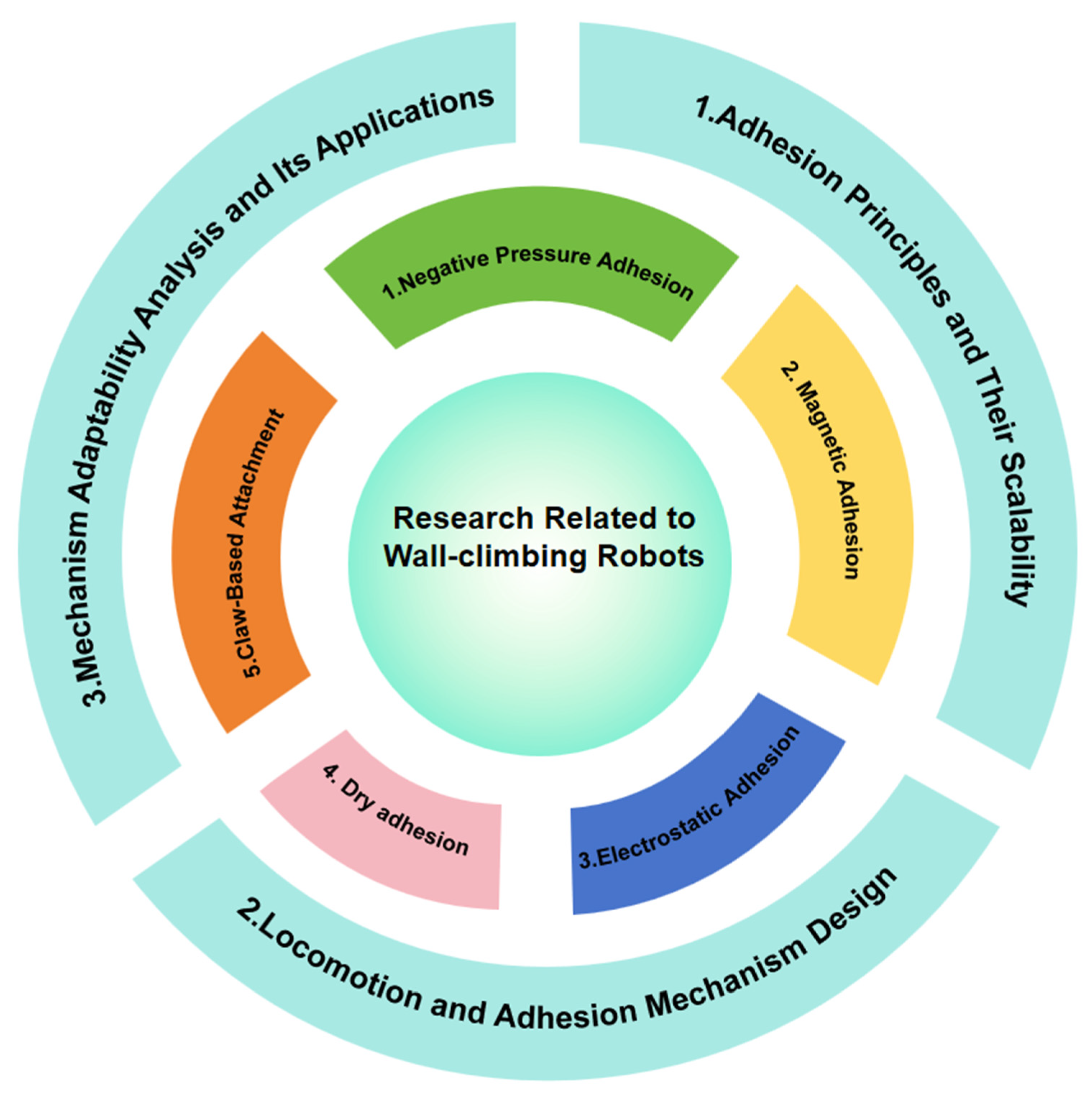
2. Research Related to Wall-Climbing Robots

Different attachment strategies of wall-climbing robots are one of the major topics of investigation. The efficiency of attachment is the key to the flexible mobility and operation of wall-climbing robots in varied contexts. Due to varying working situations and requirements, wall-climbing robots generally employ alternative attachment methods and motion strategies. So far, the basic motion strategies of wall-climbing robots include wheeled, legged, tracked, etc. The following will classify them according to the adhesion principles and their scalability, introduce the movement and attachment mechanism under different attachment methods, and examine the key and novel features of the mechanism design under this attachment method. Figure 1 shows the circular mind map of Section 2.

2.1. Negative Pressure Adhesion

2.1.1. Adhesion Principles and Their Scalability

Negative pressure adhesion is a relatively mature and widely used technology. Wall-climbing robots use negative pressure adhesion to achieve stable motion on vertical or inclined surfaces. This technique relies heavily on creating a localized low-pressure region inside the suction cup, which allows the atmospheric pressure outside the suction cup to push the robot towards the surface, resulting in a solid adsorption. Different pressure-generating devices such as vacuum pumps, centrifugal fans, and propellers are usually available.
Early wall-climbing robots mainly used suction cups as the adsorption device, which relied on a vacuum pump or a vacuum generator (vacuum ejector) to extract the air inside the suction cups and the wall surface, enabling quick and effective adhesion to the wall surface. The adhesion principle is shown in Figure 2a. The suction cup is made of an elastic material with a cup-like structure, which can fit the wall and form a seal when negative pressure is applied. The following equation can be used to calculate the adsorption force provided by the suction cup [19].
F s u c t i o n   c u p s = ( P o u t s i d e P i n s i d e ) × S
where F s u c t i o n   c u p s is the adhesion force (unit: N), P o u t s i d e is the pressure outside the suction cup (unit: Pa), P i n s i d e is the pressure inside the suction cup (unit: Pa), and S is the effective contact area of the suction cup in contact with the wall (unit: m2).
It is not difficult to derive from the formula that, in order to improve the adhesion stability of the wall-climbing robots, the desired effect can be achieved by increasing the effective area of the contact and by employing a larger number of suction cups with a larger area [20,21]. Therefore, according to Equation (1), it is clear that suction cup adhesion exhibits good scalability. By enlarging the suction cup size, enhancing sealing performance, and increasing the power of the vacuum pump, greater load capacity can be achieved, making it suitable for medium-sized and large-sized robots. However, for small-sized micro robots, the smaller the suction cup, the more significantly surface micro-roughness (such as fine bumps, particles, or textures) increases the likelihood of leakage at the suction cup edge. Additionally, the short edge length of small suction cups makes it difficult to generate sufficient pressing force to ensure full contact with the wall surface, leading to a sharp increase in sealing difficulty. At the same time, vacuum pumps are hard to miniaturize, making it difficult to maintain sufficient negative pressure adhesion. As a result, the application of this method on small-scale platforms is limited.
The centrifugal fan generates a pressure difference by rotating, which makes the wall-climbing robot adhere to the wall surface, which mainly involves Bernoulli’s equation and the law of conservation of momentum in fluid dynamics, and the adhesion principle is shown in Figure 2b.
P + 1 2 ρ V 2 + ρ g h = C
where P is the pressure at a point in the fluid (unit: Pa), V is the flow velocity of the fluid at that point (unit: m/s), ρ is the fluid density (unit: kg/m3), g is the acceleration due to gravity (unit: m/s2), h is the height of the point above a reference level (unit: m), and C is a constant representing the total mechanical energy per unit volume (unit: Pa).
The centrifugal fan of Figure 2b creates a localized low pressure in the robot adsorption region by rotating at high speeds, drawing air in from the inlet and accelerating it out of the outlet. Assuming that the airflow velocity generated by the centrifugal fan is and the velocity of the surrounding stationary air is =0, the pressure difference ΔP can be expressed according to Bernoulli’s equation as
Δ P = P o u t P i n = 1 2 ρ ( V i n 2 V o u t 2 )
Since V o u t = 0 , this simplifies to
Δ P = 1 2 ρ V i n 2
Assuming that the effective adsorption area is S, the difference between the internal and external atmospheric pressure produces an adsorption force F of
F N = Δ P · S = 1 2 ρ V i n 2 S
If the wall-climbing robot can be stably attached to the wall, the mass of the robot is m, with the coefficient of wall friction, then there is
F = F N μ = 1 2 ρ V i n 2 S μ m g
Therefore, the minimum required airflow velocity is:
V i n 2 m g ρ S μ
where V i n is the minimum required airflow velocity (unit: m/s), m is the mass of the robot body (unit: kg), g is the acceleration due to gravity (unit: m/s2), ρ is the air density (unit: kg/m3), S is the effective area (unit: m2), and μ is the coefficient of friction between the wall and the contact surface (dimensionless).
For centrifugal fan-based negative pressure adhesion, as indicated by the derived fan speed (Equation (7)), this method also demonstrates good scalability. In medium- and large-sized climbing robots, the adhesion capacity can be enhanced by increasing the fan speed, enlarging the fan diameter, or expanding the effective low-pressure area, thereby achieving greater load capacity and improved adaptability to wall surfaces. However, for microrobots, limitations in motor output power and the physical size of the fan significantly weaken the airflow driving capability and the resulting pressure differential, leading to insufficient adhesion force. Additionally, at the microscale, high-speed airflow tends to induce flow disturbances, which further restricts the applicability of this technique in microrobotic platforms.
Propeller thrust adhesion utilizes the airflow thrust and pressure difference generated by the propeller to create a positive pressure, allowing the wall-climbing robot to adhere to the surface. As shown in Figure 2c, the thrust F of the propeller can be derived from the momentum theorem:
F p r o p e l l e r = m ˙ ( V o u t V i n )
Let m ˙ be the mass flow rate:
m ˙ = ρ A V a v g
Let V a v e r a g e be the average velocity across the propeller disc area:
V a v g V o u t + V i n 2
Then the expression for the propeller thrust F p r o p e l l e r is:
F p r o p e l l e r = 1 2 ρ A V o u t 2 V i n 2
where F   p r o p e l l e r is the propeller thrust (unit: N), ρ is the air density (unit: kg/m3), A is the effective area of the propeller (unit: m2), V o u t is the airflow exit velocity (unit: m/s), and V i n is the airflow inlet velocity (unit: m/s).
According to the thrust expression F   p r o p e l l e r derived from Equation (11), the positive pressure can be significantly increased by enlarging the propeller diameter, increasing the rotational speed, or optimizing the airflow guidance structure. These measures enhance the normal force between the robot and the wall surface, thereby improving attachment stability. However, for micro-scale robots, the downsizing of the propeller leads to a significant reduction in the mass of air propelled per unit time, resulting in insufficient thrust to counteract the robot’s own weight or to achieve effective adhesion. Moreover, the energy efficiency of miniaturized motors is often inadequate to meet the demands of high rotational speeds and high thrust output. As a result, the application of propeller-based thrust adhesion is limited in micro-scale robotic platforms.

2.1.2. Locomotion and Adhesion Mechanism Design

  • Negative Pressure Adhesion with Suction Cups
Negative pressure adhesion wall-climbing robots usually use suction cups as the attachment mechanism, and most of the robots adopt legged locomotion [22,23,24,25,26,27]. From the perspective of kinematic topology, legged climbing robots can be broadly categorized into serial, tree-like, and parallel mechanisms. Serial mechanisms are typically seen in bipedal robots, tree-like mechanisms are common in multi-legged robots, and parallel mechanisms are increasingly being applied for precise control of suction feet or posture adjustment platforms, offering high stiffness and fast response.
For the serial mechanism, Shi and Xu proposed a 6-degree-of-freedom humanoid wall-climbing robot based on the principle of negative pressure adhesion (Figure 3a). This robot consists of suction motors, fixed motor frames, turbo wheels, and flexible soles on its legs. It features flexible adhesive feet, strong adaptability, excellent anti-tipping performance, and high friction against the wall surface [24]. However, when a bipedal wall-climbing robot ascends a vertical surface or transitions between walls, the relative pose between its two feet cannot be arbitrary. This reduces the required degrees of freedom while still demanding sufficient flexibility. The W-Climbot addresses this challenge with a symmetric 5-degree-of-freedom configuration (Figure 3b). It is composed of three T-joint modules, two I-joint modules, and two suction cup modules, all connected in series. Even if the robot cannot reach the target configuration in a single climbing step, a feasible intermediate configuration can be planned along the trajectory to ensure continuous movement [25].
For the tree-like mechanism. Japanese scholars Kazuyuki developed a multipedal robot that can climb uneven walls, corner walls, large pipes, and small pipes in parallel (shown in Figure 3c), and flexible mechanisms were applied to various parts of the robot so that the stiffness of the robot decreases gradually from the torso to the suction cups. Thus, the suction cups are able to adapt to small depressions and protrusions on uneven surfaces, while the flexible torso is able to adapt to the curves of the wall. With the help of different flexibility, the robot is able to passively adapt to the unevenness and curvature of the wall surface [26]. Meanwhile, compared to the bipedal wall-climbing robot, the multi-legged structure provides a larger support area and a more uniform distribution of the center of gravity, which enables the robot to have higher resistance to tipping on vertical walls or other complex surfaces. The multi-legged robot designed by Shang further innovates the kinematic architecture (shown in Figure 3d) by configuring each leg with 3 active degrees of freedom and one passive ankle joint. The design of the adsorption mechanism abandons a single large-area suction cup and adopts a multi-point support structure, which is combined with a distributed adsorption mechanism based on the principle of a three-point fixed surface to circumvent the risk of vacuum leakage through discrete adsorption points and significantly enhance the robustness of the motion in unstructured environments [27].
Parallel mechanisms offer superior rigidity, load capacity, and positioning accuracy compared to serial or tree-like legged robots. In recent years, Rosyid et al. developed a series of climbing robots based on 3PRRR mechanisms, showing clear technical progression. In 2022, they proposed a reconfigurable parallel climbing robot for on-structure machining [28]. The design featured a modular 3PRPR or 3PRRR structure (Figure 3e), allowing flexible DOF configurations (5 or 6 DOF). Adhesion pads—vacuum or magnetic—enabled motion on curved surfaces via coordinated gaits. In 2023, a walking parallel robot was introduced [29]. It used a symmetric 3PRRR mechanism with three actuated prismatic joints. The robot achieved both manipulation and locomotion using only three actuators. It supported two walking gaits—rotational and translational—based on alternating suction of base and end-effector pads. Dynamics were modeled and experimentally verified. In 2024, they presented a large-scale suction-based robot for wall painting [30]. As shown in Figure 3f, it employed a similar 3PRRR mechanism. Three base-mounted and three end-effector suction cups allowed stable step-by-step vertical climbing. The robot demonstrated safe, repeatable motion on large vertical surfaces.
Figure 3. Suction-based legged wall-climbing robot. (a) 6 DOF humanoid biped robot [24]. (b) W-Climbot biped robot [25]. (c) Flexible multi-legged robot [26]. (d) Multi-legged robot with distributed suction-based adhesion [27]. (e) Reconfigurable parallel wall-climbing robot [28]. (f) Large-scale suction-based parallel climbing robot [30].
Machines 13 00521 g003
Some wall-climbing robots employing negative pressure adhesion via suction cups use crawlers as their locomotion method [31,32]. For example, Ge et al. proposed a tracked wall-climbing robot based on passive suction cups (Figure 4a). Its kinematic mechanism enables the dynamic redistribution of suction forces through a specially designed guideway. This guideway, developed based on experimental data of passive suction cup behavior, ensures that the front suction cups consistently maintain sufficient normal reaction force during climbing while coordinating the load distribution among multiple cups. The adhesion system adopts a mechanically coupled design of passive suction cups and guide rails, achieving optimization of suction force without active control, thereby significantly reducing system complexity [31].
In contrast, the MultiTrack robot developed by Lee et al. integrates multi-chain tracks with pneumatic adhesion technology in an innovative manner (Figure 4b). Its motion system consists of five independently driven modules, two connecting links, and six active joints, forming a multi-degree-of-freedom serial mechanism. Center-mounted steering suction pads provide transitional assist torque, enabling the robot to flexibly traverse corners and narrow surfaces (e.g., wall widths > 130 mm). The adhesion mechanism comprises distributed pneumatic suction cup arrays, with six cups integrated into each track. Mechanical valves and guideways autonomously switch the suction state: suction cups open and close according to their contact phase as the tracks rotate. Combined with kinematic optimization and stability analysis under extreme conditions, this design supports a high load capacity (70 kg body weight with 15 kg payload), while enabling seamless transitions from the ground to vertical surfaces, showcasing the unique advantages of crawler mechanisms in continuous motion and adaptability to complex environments [32].
2.
Centrifugal Fan Negative Pressure Adhesion
Centrifugal fans create negative pressure zones mainly by generating centrifugal force through rotating blades. Regarding the design of mobile mechanisms for robots, wheeled [33,34,35], tracked [36], and hybrid configurations [37] have become the mainstream solutions to achieve fast and smooth motion.
Among wheeled robots, Huang’s bridge inspection robot (Figure 5a) adopts a classical wheel-driven architecture. In this design, gas in the negative pressure chamber is continuously evacuated by a high-speed motor-driven impeller, enabling the robot to generate adsorption force. The key structural elements in this type of centrifugal fan robot are the negative pressure chamber and the impeller. To ensure stable adsorption during rapid wheel movement, a backward-closed impeller with excellent aerodynamic performance, large air volume, and high efficiency was selected and optimized, including impeller parameters and chamber structure [33]. Yang’s team further developed a wheeled robot (Figure 5c) featuring an innovative “low-mounted wheel body + flexible skirt” structure. By embedding the driving wheels inside a bottom ring frame combined with adaptive deformation of flexible sealing materials, the robot maintains high-speed mobility while adapting to various wall curvatures and overcoming shallow trench obstacles [34].
For tracked robots, Jilin University conducted optimization based on a tracked platform (Figure 5b). They established a functional relationship among impeller blade exit angle, impeller inlet diameter, and blade number as design variables, with negative pressure as the dependent variable, using the Kriging surrogate model. The impeller parameters were optimized via a genetic algorithm (GA), resulting in a 27.06% increase in negative pressure compared to the original design [35].
Regarding hybrid solutions, the Institute of Robotics and Intelligent Manufacturing, Chinese Academy of Sciences, developed a wheel-track composite robot (Figure 5d). This robot employs an omni-directional belt-wheel mechanism, combining the continuous surface contact advantages of tracks with the independent drive of wheels. The hybrid drive achieves circumferential and axial composite motion on cylindrical surfaces through the coordinated action of multiple pulley units, overcoming the limitation of traditional wheeled robots which can only steer along straight paths [37].
In underwater applications, centrifugal fan-based negative pressure suction technology is also employed to address challenges such as high pressure, high humidity, and rough surface conditions. For instance, Zhao et al.’s underwater cleaning robot (Figure 6a) uses a wheeled drive system combined with multiple vortex-based negative pressure suction units [38]. Each suction unit generates stable negative pressure at the center of a sealed cylindrical cavity via a high-speed backward-curved impeller, creating swirling water flow for non-contact adhesion. The four suction units are symmetrically arranged beneath the robot, providing both adhesion and enhanced postural stability, enabling efficient, stable locomotion on vertical underwater surfaces. Similarly, Tang et al.’s underwater inspection robot (Figure 6b) also adopts a centrifugal fan-style negative pressure suction mechanism [39]. Two electrically driven vortex suction cups are symmetrically mounted on the robot’s sides, each powered by an independently driven high-speed impeller producing swirling water flow and negative pressure for wall adhesion. The robot integrates a four-wheel independent drive and steering system with a deformable body adjustment mechanism, allowing flexible adaptation to complex underwater structures like platform columns and curved surfaces.
3.
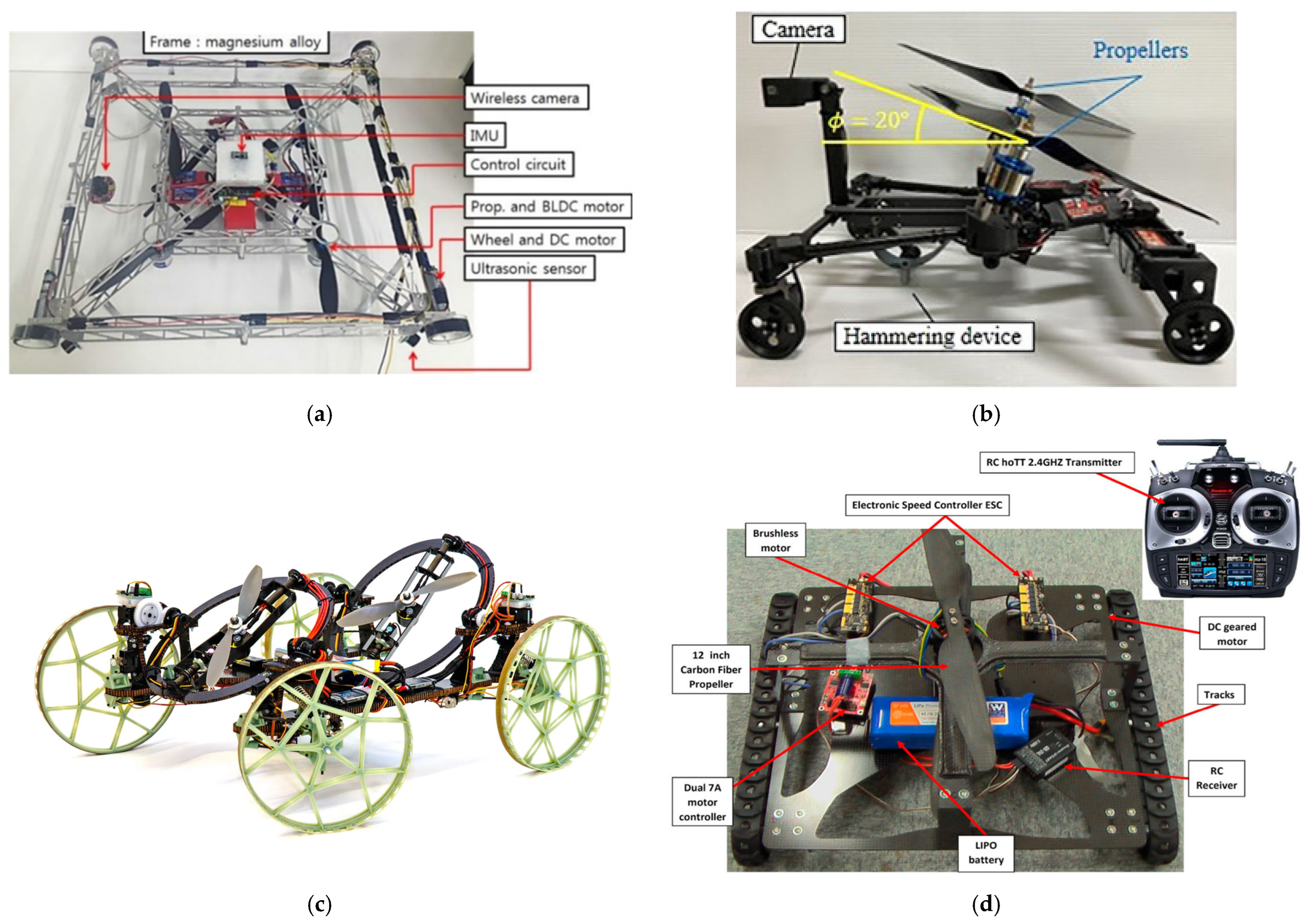
Propeller Thrust Adhesion
The motion mechanism design of wall-climbing robots utilizing propeller thrust adhesion is typically based on traditional mobile platforms, enhanced by the dynamic modulation of propeller-generated thrust. These systems are primarily divided into wheeled [40,41,42] and tracked [43] configurations, with wheeled types being the more prevalent approach.
For instance, the quadrotor-based wall-climbing robot shown in Figure 7a adopts a thrust-assisted wheeled design, where vectored rotor thrust enables wall adhesion, while wheel-driven locomotion ensures high-speed traversal on vertical surfaces. This design also supports smooth switching between flight and wall-climbing modes, offering high maneuverability and operational safety [40]. Another example is a human-designed robot that employs a dual-propeller wheeled mechanism (Figure 7b), featuring two symmetrically arranged propellers for counter-thrust generation. Compared with the quadrotor configuration in Figure 7a, this design eliminates the need for external cables, thereby avoiding issues related to weight and bulk. By adjusting the tilt angle of the propellers relative to the robot body, a downward airflow is created between the robot and the wall, enhancing adhesion and maintaining stable attachment to vertical surfaces [41]. The Beijing Institute of Technology (BIT) further proposed a wheeled robot equipped with a differential steering mechanism and a front–rear split propeller layout (Figure 7c). By rotating the front and rear propellers in an anisotropic manner, this configuration suppresses airflow interference and improves both locomotion accuracy and disturbance rejection [42].
As for tracked robots, a representative example is the EJBot II, developed by the University of Surrey (Figure 7d). It combines a large-diameter front track wheel with a tiltable propeller system to generate upward thrust. This propulsion, coupled with track traction, enables the robot to seamlessly transition from ground to vertical surfaces, achieving air–ground versatility. However, EJBot II faces challenges such as control complexity and limited navigational stability that warrant further optimization [43].

2.1.3. Mechanism Adaptability Analysis and Its Applications

As the core component of negative pressure adhesion, suction cups have natural mechanical adaptability with legged locomotion mechanisms. Legged robots realize bionic gait through discrete foot contact points, while the suction cups can build a local vacuum sealing cavity in the foot touching area, providing continuous and stable adsorption force to make up for the defects of discrete contact surfaces that are prone to pressure loss. At the control level, the fast adsorption-release characteristics of the suction cups are highly compatible with the needs of foot stripping and posture adjustment in legged gait, and support dynamic wall transition. Structurally, the suction cups are easily miniaturized and integrated into the foot end, avoiding the spatial conflicts caused by complex joints in legged locomotion mechanisms. In contrast, propellers and centrifugal fans, which are continuous airflow adsorption mechanisms, require stabilized airflow channels, resulting in poor adsorption effects, and are difficult to adapt to the intermittent contact pattern of legged locomotion.
The centrifugal fan generates a continuous negative pressure zone by means of a high-speed impeller and is suitable for wheeled/tracked motion. Its uninterrupted adsorption characteristics cover a large contact area between the wheel/track and the wall, and its continuous high flow rate quickly compensates for localized leakage due to wall bumps or gaps, significantly improving the anti-disturbance capability in high-speed motion. The centrifugal fan can be embedded inside the wheel/track chassis, which saves axial space compared with the external propeller mechanism, and is more conducive to lightweight design. While the traditional suction cup relies on the vacuum pump for active pumping, which is susceptible to interruption of the adsorption due to the sealing failure during the high-speed rolling of the wheel/track, the passive negative pressure mechanism of the centrifugal fan is thus more robust [44].
The propeller mechanism can be adjusted by the tilt angle to generate both positive pressure on the vertical wall and tangential driving force, which is suitable for continuous wheel/track motion. The positive pressure provided by the propeller mechanism can be converted into effective friction between the wheel/track and the wall surface to support high-speed movement. Meanwhile, the axial thrust of the propeller mechanism gives the robot the ability to cross recessed obstacles or realize land–air multimodal transition, which expands the motion dimensions of wheeled/tracked robots [45]. Meanwhile, propeller thrust has difficulty matching the discrete gait requirements of legged mechanisms, but can be combined with wheeled/tracked mechanisms to form a hybrid drive system, which realizes complex terrain adaptation through dynamic distribution of thrust.
Therefore, the compatibility between different adhesion methods and locomotion mechanisms should be systematically considered in accordance with specific task scenarios. For “sensing-only” tasks—such as monitoring, inspection, or environmental perception—robot design should prioritize mobility and adaptability to wall surfaces, with relatively low requirements for payload. In such cases, lightweight and responsive adhesion mechanisms, such as miniaturized suction cups and centrifugal fan-based negative pressure systems, are more appropriate. These can be effectively combined with wheeled or tracked locomotion to achieve wide-area coverage. In contrast, for “sensing-and-acting” tasks—such as spraying, cleaning, non-destructive testing, or assembly—the robot must achieve strong positioning and reaction support on the surface. Therefore, designs should favor stronger and more structurally stable adhesion schemes, such as multi-suction-cup arrays or hybrid adhesion structures, together with legged locomotion systems to enable multi-point contact and adjustable working postures.

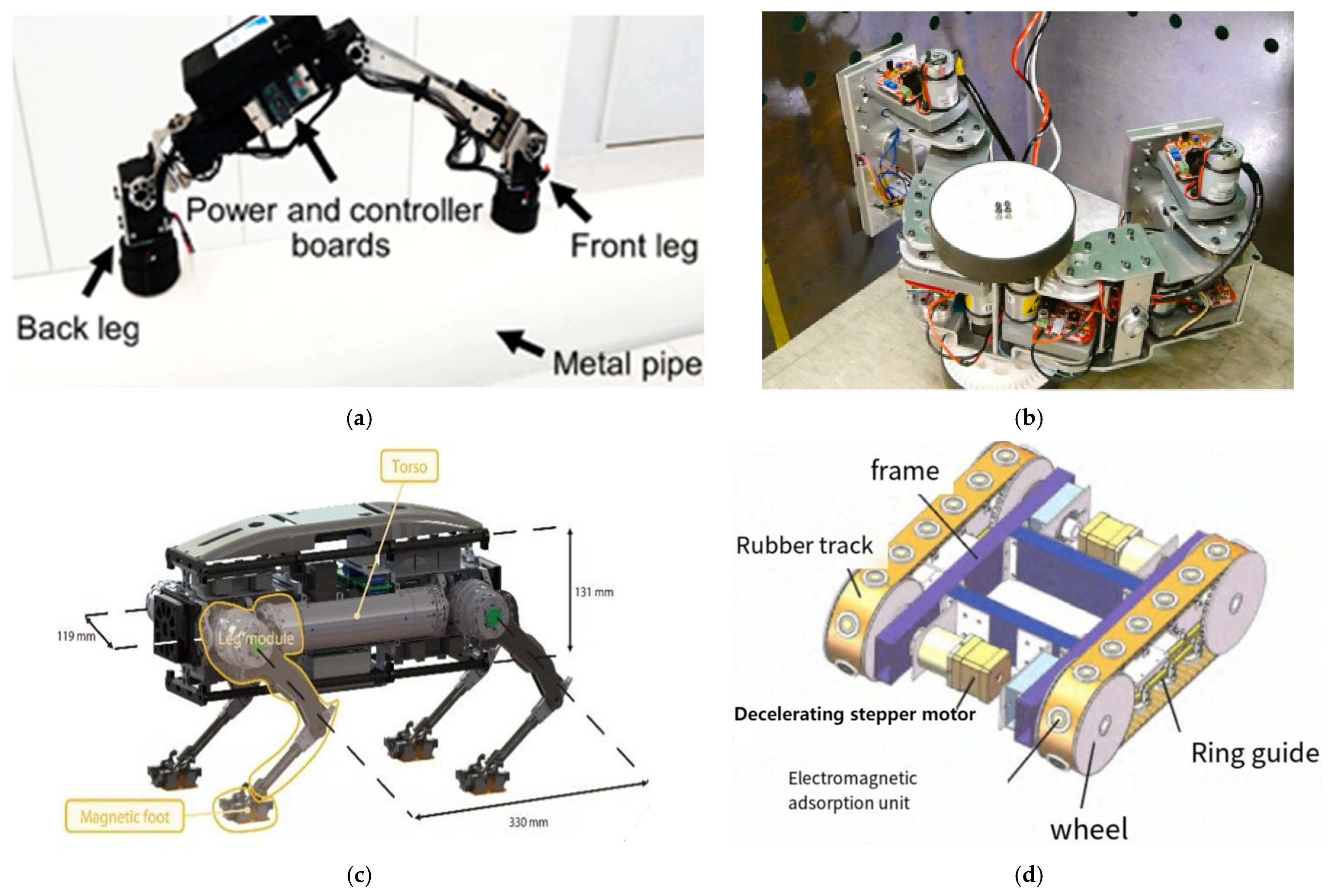
2.2. Magnetic Adhesion

2.2.1. Adhesion Principles and Their Scalability

The principle of magnetic adhesion is based on the interaction between a magnetic field and ferromagnetic materials (such as iron, nickel, cobalt, etc.). When a magnet approaches these materials, it induces magnetization within them, generating an attractive force that causes the object to adhere to the surface of the magnet. According to the working principle and design characteristics of the adhesion device, the wall-climbing robot’s adhesion system can be categorized into permanent magnetic adhesion devices and electromagnetic adhesion devices, and hybrid magnetic systems that combine both types to balance energy efficiency and controllability.
A permanent magnetic adhesion device uses permanent magnets (such as neodymium-iron-boron or samarium-cobalt) to generate a constant magnetic field that adheres to ferromagnetic materials. When a permanent magnet approaches a ferromagnetic surface, it induces magnetization within the material, forming a closed magnetic circuit. Magnetic flux lines enter the ferromagnetic material from one pole of the magnet and return to the magnet through the other pole, thus creating an attractive force between the two. When a closed magnetic circuit is established between the permanent magnet and the ferromagnetic surface, and the magnetic flux density is evenly distributed, the adhesion force F P e r m a n e n t can be approximated as:
F P e r m a n e n t = B 2 · A 2 μ 0
where F P e r m a n e n t is the magnetic adhesion force (unit: N), B is the magnetic flux density (unit: T), A is the effective adhesion area (unit: m2), and μ 0 is the permeability of free space (unit: H/m).
Therefore, as indicated by Equation (12), permanent magnet adhesion demonstrates good scalability for medium- and large-sized robots. Enhanced adhesion force can be achieved by increasing the magnet’s cross-sectional area A, selecting materials with higher magnetic energy products to improve B, and optimizing the magnetic circuit design. However, for small-scale microrobots, as the magnet size decreases, the closed-loop efficiency of the magnetic circuit deteriorates, leading to a nonlinear increase in magnetic leakage. This significantly reduces the effective utilization of both the adhesion area A and the magnetic flux density B. Additionally, the steep magnetic field gradient at the edges of micro-magnets tends to generate large localized air gaps δ when facing surface irregularities (such as micro-protrusions, pits, or rust spots), causing a sharp decline in adhesion force. As a result, the reliable application of permanent magnet adhesion in harsh micro-scale environments is greatly limited [46].
An electromagnetic adhesion device is a system that utilizes electric current to generate a magnetic field for attracting ferromagnetic materials. Its core principle is based on electromagnetic induction and magnetic adhesion. When current flows through a coil wound around the iron core of the adhesion device, it generates a magnetic field encircling the coil, magnetizing the wall surface and forming a closed magnetic circuit. For an electromagnet with a soft magnetic core, where the air gap is assumed to be the dominant magnetic reluctance, the adhesion force F e l e c t r o m a g n e t i c can be derived based on the magnetic circuit law as follows:
F e l e c t r o m a g n e t i c = ( N I ) 2 · μ 0 · A 2 δ 0
where F e l e c t r o m a g n e t i c is the adhesion force (unit: N), N is the number of coil turns, I is the electric current (unit: A), μ 0 is the permeability of free space (unit: H/m), A is the effective adhesion area (unit: m2), and δ 0 is the air gap length (unit: m).
The core design of electromagnetic adhesion devices lies in the number of coil turns, while the strength of the current, the shape and size of the magnetic core, and the arrangement of the coils also significantly affect the final adhesion performance. A well-designed system can make the most of limited space and resources to achieve optimal adhesion. Although electromagnetic adhesion allows continuous adjustment of adhesion force via current control, the generated magnetic field strength is inherently limited, and prolonged current flow causes significant heat generation. This imposes strict requirements on the robot’s endurance and energy storage.
According to Equation (13), in medium- and large-sized robots, stronger dynamic adhesion can be achieved by increasing the core cross-sectional area A, improving the ampere-turns NI, and optimizing heat dissipation design. However, for small-sized microrobots, the limited body volume results in reduced space for coils, which constrains the maximum achievable ampere-turns NI within physical boundaries, making it difficult to meet the minimum adhesion force requirement. In addition, high-power miniature switching power supplies are difficult to implement. Under continuous current, Joule heating cannot be effectively dissipated in a confined volume, and temperature rise beyond material limits may lead to adhesion failure. Currently, this issue shows promise of being addressed by MEMS-fabricated 3D coils, which can increase the turn density [47,48].

2.2.2. Locomotion and Adhesion Mechanism Design

  • Permanent Magnetic Adhesion
Wall-climbing robots with permanent magnetic adhesion are more closely integrated with continuous motion mechanisms such as wheeled [49,50,51,52,53] and tracked [54,55,56,57] systems in both technological development and practical applications. In wheeled mechanisms, magnetic wheels serve as the core component. By optimizing magnetic circuit design and material selection, these wheels can deliver strong adhesion while maintaining a lightweight structure [49]. For instance, Xu, from Southwest University of Science and Technology, developed a wall-climbing robot with magnetic wheels and an obstacle-crossing mechanism based on permanent magnet blocks fixed along a track (Figure 8a). A Halbach array configuration was used to significantly enhance the magnetic field strength and unidirectional adhesion force, thereby improving overall wheel performance [50].
In typical designs, permanent magnets are placed on the outer surface of the wheel to maintain direct contact with the wall, which, however, can scratch surfaces and make detachment difficult. Addressing this issue, Zhang from Hebei University of Technology proposed an embedded magnet configuration inside the wheel structure to reduce surface damage (Figure 8b) [51].
Beyond magnet arrangement, some researchers have explored novel wheel designs to enhance terrain adaptability. Eto and Asada from MIT proposed a structure (Figure 8c) featuring a pair of rocker arms with magnetic spherical wheels. Each wheel integrates a 2-degree-of-freedom rotating magnetic adhesion unit, allowing the magnetic force to remain perpendicular to the contact surface at all times. Through an inelastic suspension system, the robot autonomously adjusts each wheel’s contact point, enabling motion over arbitrarily curved surfaces [52]. OmniClimbers, a well-known climbing robot (Figure 8d), employs three symmetrically arranged omnidirectional wheels spaced 120° apart. Each wheel surface is equipped with cylindrical magnet arrays whose spacing can be adjusted. This design not only offers high maneuverability, but also enhances adaptability to various structural materials [53].
Among tracked kinematic mechanisms, Zhang et al. developed a modular four-tracked robot utilizing permanent magnet gap-type adhesion (Figure 9a). The robot’s core motion module consists of four independently driven tracks, which are rigidly connected to the chassis via link shafts. This configuration significantly enhances wall-climbing stability and load capacity compared to traditional wheeled systems. Each track incorporates a gap-type permanent magnetic adhesion unit that enables non-contact attachment, thereby reducing wall surface abrasion. Additionally, the modular architecture allows for rapid assembly and disassembly, providing adaptability for various tasks such as weld inspection and surface polishing [54].
Zhao’s team further optimized the design by introducing a double-row magnetic track mechanism (Figure 9b). The magnetic adhesion unit is composed of rectangular permanent magnets, spacer plates, and reinforced yokes. The dual-chain layout ensures continuous adhesion, while a reinforced stamping process increases the yoke’s bending strength to withstand cyclic stresses from repeated attachment and detachment. Rubber rings positioned on both sides of the tracks improve the friction coefficient, effectively preventing slippage. This design has been successfully validated in real-world applications such as ship hull sandblasting and rust removal, demonstrating high load capacity and strong resilience to surface irregularities, including corrosion and depressions [56].
2.
Electromagnetic Adhesion
Electromagnetic adhesion (EMA) uses current-driven coils to magnetize a soft magnetic core, generating an attraction force between the robot and a ferromagnetic surface. Unlike permanent magnet systems that provide constant adhesion, EMA allows precise control of attachment and detachment by switching the current, making it especially suitable for frequent gait-based transitions in legged wall-climbing robots. Furthermore, the compact and simple structure of electromagnetic foot units favors the miniaturization of robotic platforms [58].
Inspired by the inchworm’s ability to adapt to curved surfaces, Khan, from Vidyasirimedhi Institute of Science and Technology, designed a two-legged pipe-climbing robot (Figure 10a). This robot employs electromagnetic feet housed under passive toe caps to ensure stability and adaptability on metal pipes with varying curvatures [59]. Similarly, Lin’s team at National Central University developed the HMICRobot (Figure 10b), also based on an inchworm gait. Its unique electromagnetic footpads feature 90° inward-bent edges to protect internal components from deformation due to impact or bending, and integrate ToF sensors to detect the proximity to steel surfaces, preventing collisions during foot placement [60].
In recent developments, electro-permanent magnetic (EPM) devices—combining the controllability of electromagnets with the residual holding force of permanent magnets—have shown great promise. Seungwoo Hong from KIST developed a quadrupedal climbing robot (Figure 10c) with magnetic feet that integrate EPMs and magnetorheological elastomers (MREs). These feet are connected to the legs via low-profile, compliant 3-DOF passive ankle joints, enabling efficient energy use, strong holding force modulation, and reliable adhesion on uneven substrates [61].
In contrast to legged robots, wheel/track-based EMA robots benefit from avoiding constant drag associated with permanent magnets during continuous rolling. For instance, Chen from Nanjing Forestry University proposed a crawler robot (Figure 10d) with evenly distributed EMA units along both tracks. These units are activated when in contact with the lower section of the ring track, generating controllable adhesion during motion [62]. Another example by Tarapongnivat et al. uses omnidirectional wheels with hybrid rubber rollers and embedded electromagnets, producing asymmetric friction and controlled magnetic adhesion. The tested design showed a favorable ratio of adhesive force to robot weight, ensuring stable vertical climbing on ferromagnetic walls [63].

2.2.3. Mechanism Adaptability Analysis and Its Applications

Based on the method of magnetic field generation, magnetic adhesion wall-climbing robots can be classified into permanent magnetic adhesion and electromagnetic adhesion.
Permanent magnetic adhesion provides a high and stable magnetic field strength, but suffers from limited controllability. Although some researchers have proposed regulating magnetic force by varying the air gap between the permanent magnet and the ferromagnetic surface [64], the mechanisms required to adjust this gap are typically bulky and slow to respond, making them unsuitable for legged robots that require frequent attachment and detachment during locomotion. In contrast, for wheeled or tracked mechanisms—where continuous contact with the wall is maintained—permanent magnets can deliver sustained and reliable adhesion. These systems are lightweight and do not require a power supply, and are often embedded in the wheels or mounted along the tracks [65,66,67], contributing to structural simplification and weight reduction.
However, even with external or embedded mounting, the contact point between the wheel and the wall constantly shifts during high-speed movement. This limited contact area can reduce the overall magnetic adhesion effectiveness and result in low magnetic energy utilization. Furthermore, wheeled robots experience higher frictional resistance during turning, and since permanent magnets cannot actively modulate the normal force between the wheel and the wall, additional driving force is required to execute turns, thereby increasing mechanical wear. Electromagnetic adhesion, on the other hand, generates a controllable magnetic field via current-driven coils. Its key advantage lies in its adjustable magnetic force and fast response time, making it well-suited for legged robots that require dynamic modulation of adhesion. By altering the magnitude or direction of the input current, the magnetic field can be rapidly strengthened, weakened, or switched off, enabling efficient transitions between attachment and detachment states.
Nevertheless, electromagnetic systems require a continuous power supply to maintain the magnetic field, leading to high energy consumption. In addition, the complexity of the circuitry and the demands of heat dissipation can increase system weight, which may hinder lightweight design. Electromagnets are also susceptible to sudden loss of adhesion in the event of a power failure, necessitating redundant power sources [68] or backup magnetic circuits to ensure safety. To mitigate energy loss, some researchers have proposed pulse power supplies and low-power magnetic circuit optimization schemes, which reduce thermal losses while maintaining magnetic stability. However, their dynamic performance and long-term reliability remain to be fully validated [69].
Based on the above analysis of mechanism adaptability, for inspection and monitoring tasks that do not require manipulation, the robot body should be as compact and lightweight as possible, enabling rapid movement to scan the environment, with sensor-based data acquisition as the primary goal. Accordingly, the required adhesion force only needs to meet the basic demands of supporting the robot’s weight and resisting minor disturbances, making the overall system design more oriented toward lightweight and low-power consumption. This is well aligned with the characteristics of permanent magnet adhesion, which offers structural simplicity, no need for continuous power supply, and low maintenance costs. When combined with highly maneuverable wheeled or tracked mechanisms—such as the aforementioned OmniClimbers robot with omnidirectional wheels, the magnetic spherical wheel robot, and the four-tracked permanent-magnet-adhesion robot—it enables long-duration, energy-efficient inspection missions.
In contrast, for “operation-oriented” tasks, such as hull rust removal or spray coating on ferromagnetic wall surfaces, the robot must maintain stable adhesion under complex loading conditions. The magnetic adhesion system must also be capable of real-time adjustment to accommodate force changes caused by manipulator operation or shifts in the robot’s center of mass. Electromagnetic adhesion, with its controllable magnetic force and rapid response, is well-suited for integration with legged or multi-jointed platforms, providing dynamic support in tasks requiring frequent adhesion/de-adhesion switching and posture adjustments. However, such systems impose higher demands on power supply stability, thermal management, and control strategies.

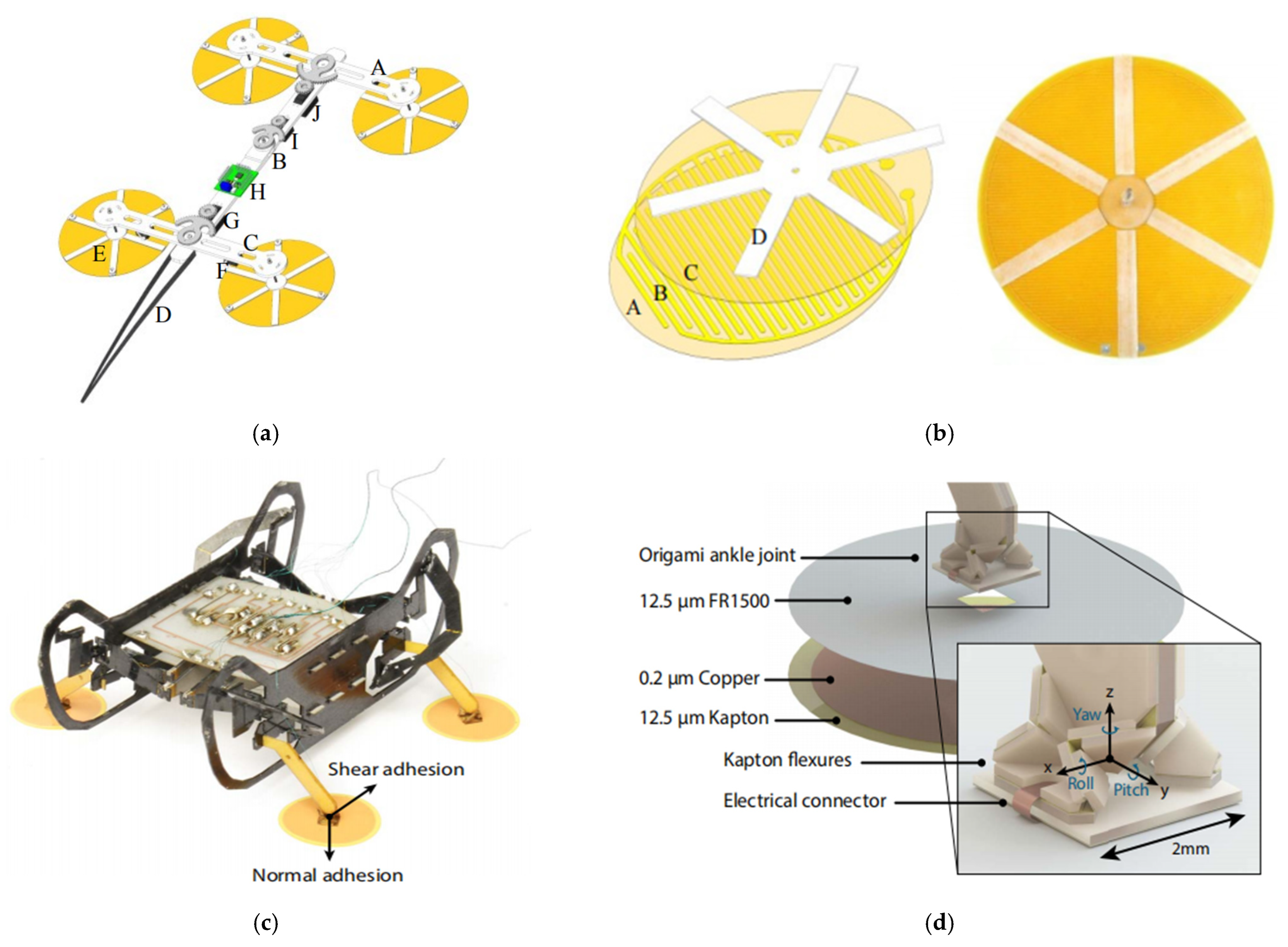
2.3. Electrostatic Adhesion

2.3.1. Adhesion Principles and Their Scalability

Electrostatic adhesion refers to the phenomenon where a charged object induces an equal and opposite charge in a nearby uncharged object through electrostatic induction. According to the principle that opposite charges attract, an attractive force is established between the two. In wall-climbing robots, high-voltage electrostatic forces are typically applied to conductive electrodes mounted on the robot body. When these electrodes are charged, they create a strong electric field that polarizes the dielectric material of the wall surface, thereby generating bound charges. The Coulomb interaction between the free charges on the electrodes and the induced charges in the wall gives rise to the adhesion force. This mechanism indicates that the formation of polarized charges on the wall surface is the physical basis for electrostatic adhesion [70].
For an ideal parallel-plate electrostatic adhesion structure, the electrostatic adhesion force F e l e c can be expressed as:
F e l e c = 1 2 · ε 0 · ε r A · V 2 d 2
where F e l e c   is electrostatic adhesion force (unit: N), ε 0 is vacuum permittivity, ε r is relative permittivity (related to the surface material), A is effective contact area of the electrode (unit: m2), V is applied voltage (unit: V), and d is distance between the electrode and the wall surface (unit: m)
Electroadhesion is limited in its application to medium- and large-sized climbing robot platforms. According to Equation (14), the electroadhesive force is inversely proportional to the distance between the electrodes and the wall surface. Therefore, even minor surface irregularities or undulations during operation can significantly increase the distance dd, leading to a sharp decrease in adhesion force. Additionally, as the size of the adhesion device increases, the electrode area and operating voltage grow, which greatly raises the risk of corona discharge, dielectric breakdown, or leakage between the plates. Electroadhesion is also highly sensitive to environmental factors such as humidity, surface contamination, and electromagnetic interference, making it difficult to operate reliably in harsh environments, such as outdoors, humid conditions, or corrosive industrial settings. Consequently, electroadhesion is generally unsuitable for medium- to large-scale climbing robots.
In contrast, electroadhesion technology demonstrates clear advantages in the field of micro-scale climbing robots. This is because electroadhesion devices typically consist of two electrodes and have a simple structure that requires neither complex mechanical components nor magnetic systems. This minimalist design is particularly well-suited for microrobots with limited onboard space. Furthermore, modern fabrication technologies, such as MEMS/NEMS processes, enable the development of high-density and high-precision flexible or thin-film electrode arrays, thus promoting the miniaturization and integration of electroadhesive climbing robots [71].
Typical adsorption electrodes include both single electrode and comb electrode forms. A single electrode creates an electrostatic field between the electrode and the wall surface by applying a DC voltage to the electrode. This electric field leads to the polarization of the charge on the wall surface, which in turn generates electrostatic force for the adsorption of the target object. The comb electrode consists of a plurality of elongated electrodes arranged in parallel. The advantage of comb electrodes is that their unique structural design significantly enhances the strength of the local electric field, thereby substantially increasing the adsorption effect. By using comb-shaped electrodes, the electrostatic adhesion performance can be flexibly optimized from the perspective of electrode design. Compared with single electrodes, comb-shaped electrodes also show higher flexibility and faster response speed in adsorption control, which is favorable for wall-climbing robots to perform complex actions.

2.3.2. Locomotion and Adhesion Mechanism Design

  • Static Foot Pad Adhesion
Electrostatic adhesion wall-climbing robots typically adopt inchworm-inspired locomotion by employing origami structures or soft materials that allow the entire body to deform and conform to diverse surface geometries [72,73,74,75]. These systems primarily consist of two functional components:
  • Electrostatic footpads, which generate adhesion through electrostatic forces.
  • Flexible actuators, which drive the deformation and coordinated movement of the robot body.
In 2018, Cao and Qin introduced a cable-free soft robot (Figure 11a), consisting of a deformable body actuated by dielectric elastomers and two paper-based feet embedded with electrostatic actuators. The robot achieves locomotion by alternately actuating the body and footpads, enabling effective adhesion and release cycles [72]. In 2019, Qin further developed a soft crawling robot (Figure 11b) that supports both linear and turning motions by sequencing different actuators. Thanks to the rapid response of the soft structure and electrostatic adhesion, the robot achieved a steering speed of 15.09°/s [73]. In 2023, Hu designed an origami-based inchworm robot (Figure 11c) featuring flexible electrostatic footpads as electrically controlled adhesive units. The robot demonstrates strong adhesion and surface adaptability on moderately curved surfaces [74]. Notably, Gu proposed a wired soft-bodied robot (Figure 11d) that replaces mechanical springs with dielectric elastomer artificial muscles for rapid body deformation. This design enabled vertical climbing at speeds up to 0.75 body lengths per second on wood, paper, and glass surfaces, demonstrating strong adhesion and versatility [75].
Legged electrostatic adhesion wall-crawling robots extensively utilize electrostatic footpad mechanisms for adhesion. The quadrupedal crawling robot developed by Beijing University of Aeronautics and Astronautics (Figure 12a) relies on electrostatic adhesion force generated by adhesive footpads fabricated using flexible circuit board technology. The base of the adhesive footpad (Figure 12b) consists of a polyurethane film and a copper film. Due to the flexibility of these materials, the footpad tends to peel off or deform from the wall surface when lifted. To address this, a reinforcement layer composed of six flexible plastic rods arranged radially at the top of the footpad is incorporated to enhance structural integrity and maintain its shape [76].
The MicroRobot (Figure 12c), designed by Harvard University, also carefully considers electrode geometry, dielectric materials, and footpad stiffness. It employs a 0.2 mm copper electrode embedded in the footpad (Figure 12d) with a 12.5 mm acrylic adhesive backing, striking a balance between low stiffness and resistance to plastic deformation. The legged robot’s ankle consists of flexible elements, with the laminate folded origami-style into its final form. This allows the ankle to align simultaneously with the macroscopic surface topology, increasing the effective contact area for stable adhesion [77].
2.
Electrostatic Panel Adhesion Mechanism
Electrostatic adhesion performance mainly depends on factors such as the adhesion material relative to device characteristics, the tightness of the robot’s fit to the wall, and the size of the contact area between them. Therefore, using electrode panels with large contact areas as an adhesion mechanism has become a common design approach [78,79,80,81,82,83].
In 2007, Yamamoto and Nakashima designed a flexible electrode-based adsorption device using a flexible electrode panel fabricated from plastic films and conductive foils to adapt to the unevenness of wall surfaces. Experimental results showed that the flexible electrode panel could generate sufficient adhesion on conductive surfaces, enabling the robot to climb at a speed of 6.6 mm/s. For adsorption on non-conductive surfaces, two methods—surface pre-charging and the use of comb electrodes—allowed the Generation II prototype robot (Figure 13a) to adsorb on glass surfaces and climb at an average speed of 1.75 mm/s [78]. In 2012, Leming Wang from South China University of Technology fabricated comb electrodes as a flexible film insulated on both sides (Figure 13b) and embedded a conductive copper foil layer with good ductility and electrical conductivity in the middle. This design stores a large amount of free charge when subjected to high-voltage electrostatic force, thus generating a stronger electric field between the wall and the robot [79]. For the adsorption mechanism in electrostatic adhesion, Prahlad in 2008 proposed a flexible adhesion mechanism that induces electrostatic charge on the wall substrate by connecting a power source to a flexible pad located on the mobile robot (Figure 13c) [80]. In 2013, Liu R., Chen R., et al. proposed a coagulation adhesion mechanism for a dual-tracked wall-climbing robot (Figure 13d). Flexible electrode panels were mounted on the front and rear rollers to generate electrostatic adhesion force during motion. The robot could satisfactorily perform straight-line and steering movements; however, adhesion instability occurred on slopes with inclinations greater than 30°. This issue requires addressing the problem of electrode panels sticking to the wall during side-sliding, which sharply decreases dynamic adhesion [81].

2.3.3. Mechanism Adaptability Analysis and Its Applications
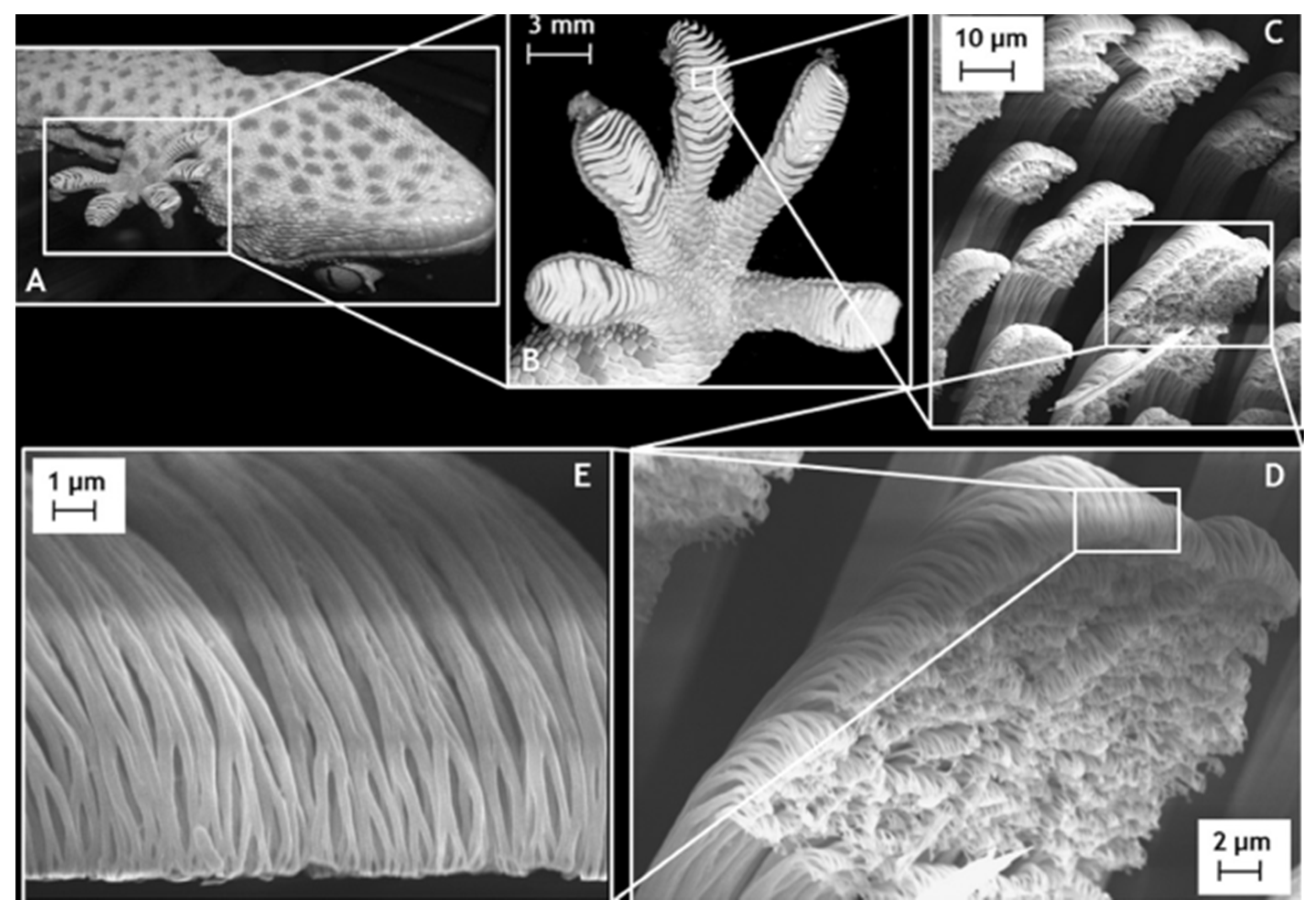
Electrostatic adhesion is highly adaptable and has a wide range of applications. Electrostatic adhesion can be applied to conductive and non-conductive walls with good environmental adaptability. The Electrostatic adhesion mechanism of the robot usually has an electrostatic foot pad and an electrostatic panel adhesion mechanism.
Electrostatic foot pads are generally used in foot-legged wall-climbing robots. For example, the key to the design of inchworm-type electrostatic adhesion wall-climbing robots lies in the foot pads of the foot and the elastic actuator of the waist, and the peristaltic movement requires the robot to have a flexible body [82,83,84], so the elastic actuator of the waist is made of flexible acrylic, artificial muscles, memory alloys, etc. The electrostatic foot pads of the foot and the electrostatic panel adhesion mechanism are usually used in foot-leg type wall-climbing robots, and the electrostatic foot pads on the foot determine the adhesion between the robot and the contact surface. The foot pads are designed to adapt to different surface roughness and material properties by optimizing the surface area, thickness, and edge profile parameters of the foot pads. It is also necessary to consider the flexibility of the foot pads in order to better fit irregular or curved surfaces, so the material will be flexible electrodes combined with elastic insulating materials and other ways to make the electrostatic foot pads have toughness.
The electrostatic panel adhesion mechanism has a large contact area with the wall and is suitable for crawler movement. Crawler-type wall climbing robots are generally designed with tracks made of flexible electrostatic adsorbent material covering the drive and guide wheels to form a closed-loop drive system. The electrically adherent track design increases the contact area to improve the adsorption effect, and also ensures that the robot can flexibly adjust its attitude in complex terrain. Due to the high resistance of the insulating film, the current flow through the electrode panels is low, so the energy consumption of the electrostatic adhesion robot is also relatively low.
Due to its inherent physical characteristics, electrostatic adhesion is more suitable for lightweight, low-power, and miniaturized inspection platforms. Its adhesion system typically consists of flexible or thin-film electrodes, featuring a simple structure, extremely low mass, and minimal energy consumption, making it easy to integrate into small-scale climbing robots for electrostatic adhesion functionality. However, it is not suitable for medium- to large-sized “operation-type” robots that require high load capacity and strong adaptability to wall surfaces. Compared to permanent magnetic or electromagnetic adhesion, electrostatic adhesion generally provides a lower adhesion force per unit area (typically ranging from several tens to several hundreds of pascals) [85], making it difficult to carry heavy tools or actuators. Therefore, it cannot meet the additional loads and posture disturbances encountered during the operational tasks of “operation-type” wall-climbing robots.

2.4. Dry Adhesion

2.4.1. Adhesion Principles and Their Scalability

Dry adhesion refers to adhesion that does not rely on liquid adhesives or glandular secretions. It is commonly observed in nature, particularly in wall-climbing organisms of the Gekkonidae family, which possess millions of microscopic structures called setae on the surface of their toe pads (Figure 14). At a finer scale, these setae branch into hundreds or thousands of even smaller structures called spatulae or villi [86]. These villi adhere tightly to wall surfaces, where van der Waals forces facilitate both stable attachment and agile movement [87].
Compared with other conventional adhesion mechanisms, dry adhesion using setae exhibits several unique advantages [88]. First, the branched and multilayered geometry of the setae—especially their high aspect ratio—enhances their flexibility and compliance, allowing effective adhesion even on rough or uneven surfaces. The ability of these structures to bend and conform to small surface depressions increases the real contact area, thereby ensuring reliable attachment [89,90,91]. Second, since van der Waals forces exist universally between materials, dry adhesion is not constrained by the material properties of the substrate, giving it broader applicability. There are two prevailing hypotheses regarding the detachment mechanism of gecko dry adhesion:
  • Microscopic hypothesis: detachment occurs when the shaft of the setae reaches a critical angle relative to the substrate, causing the adhesive contact to fail.
  • Macroscopic hypothesis: detachment occurs when the gecko’s toes hyperextend and peel away from the surface similarly to duct tape being pulled off.
Autumn and Dittmore [92] experimentally tested both hypotheses using arrays of isolated setae and the toes of live geckos. Their results demonstrated that the adhesive force is primarily dependent on shear force and not on the critical angle. Based on this, they introduced a frictional adhesion model to better explain and predict gecko adhesion behavior under varying force conditions.
In dry-adhesion wall-climbing robots, the adhesion force primarily originates from the van der Waals force between surfaces. Dry adhesive materials, such as bio-inspired microstructures or polymer nanofibers, form intimate contact with the wall surface, reducing the intermolecular distance to within several nanometers, thereby enabling the robot to adhere to the surface. For two ideal parallel surfaces, the van der Waals adhesion force per unit area can be expressed by the classical formula:
F ( d ) = A 6 π d 3
where F(d) is the attractive force per unit area, A is the Hamaker constant (which depends on the material pair), and d is the distance between the two surfaces [93].
This formula indicates that the van der Waals force decays rapidly with the cube of the separation distance. Typically, only when the contact distance is reduced to several tens of nanometers does the force become sufficient for effective adhesion. Therefore, in the design of dry-adhesion climbing robots, high-density microstructures are often employed to increase the effective contact area, thereby enhancing overall adhesion performance.
Dry adhesion relies on high-density microstructures (such as micro-setae or nanopillar arrays) to achieve close contact with the wall surface at the microscopic scale, enabling high adhesion strength and sensitive controllability for microrobots. Since van der Waals forces are significant at the nanometer scale, and because dry adhesion does not require magnetic or electric fields (thus no power supply), it is well-suited for microscale or lightweight platforms where space and energy are constrained. For medium- to large-scale “task-oriented” wall-climbing robots, the adhesion system must support greater self-weight, tool loads, and operational disturbances. According to Equation (15), the van der Waals force that dry adhesive materials rely on decreases rapidly with the cube of the distance. Even slight surface irregularities or roughness (such as coating particles or rust) can significantly reduce the adhesion effect, increasing the risk of robot detachment.

2.4.2. Locomotion and Adhesion Mechanism Design

Inspired by geckos and insect species in nature such as beetles (Figure 15a), flies (Figure 15b), and cockroaches (Figure 15c), researchers naturally associate dry-adhesion wall-climbing robots with legged locomotion systems [94,95,96]. These insects typically possess hairy or soft adhesive structures on their feet, which enable effective attachment to vertical or inverted surfaces through van der Waals forces.
For the structure of legged-footed wall-climbing robots, one of the most representative examples is Stickybot, a climbing robot developed by Autumn et al. at Stanford University in 2006. It utilizes oriented, microstructured friction-adhesive materials on its toe pads, enabling smoother climbing compared to flat adhesive pads. However, the robot exhibited limitations in wall transition performance and load capacity. Stickybot III (Figure 16a) introduced a novel tendon mechanism that significantly enhanced the adhesion pressure (up to 10.5 kPa), which is 7.5 times greater than that of a robot without tendon actuation [97].
In 2009, Nanjing University of Aeronautics and Astronautics (NUAA) developed the IBSS-III robot (Figure 16b), which features a wire-lift detachment mechanism and incorporates force-feedback control to assist in gait planning [98]. In 2021, Haomachai proposed a wall-climbing robot with an optimally bendable body possessing three degrees of freedom (Figure 16c). The dynamic lumbar flexion allows the front legs to generate greater internal and external ground reaction forces, thereby enhancing angular momentum and climbing efficiency. This design reduced energy consumption by 52% and 54% when climbing steep, rigid surfaces and soft substrates, respectively, compared to a fixed-body structure [94].
To improve the adhesive foot design, researchers at Northeastern University developed a microstructured adhesive foot with a two-stage edge-peeling mechanism (Figure 16d). The design consists of four tandem units and a rigid frame. During attachment, the foot forms a rigid structure supported by a flexible base to maximize adhesive force. During detachment, the foot is gradually peeled off from the edge due to the series configuration of the tandem links. In terms of actuation, a screw-driven rack-and-pinion mechanism is used instead of a multi-joint design, converting rotational motion into linear motion to simplify the robot’s mechanical system [99].
Dry adhesion can also be implemented in a discretized contact form through spoke-wheel-inspired structures [100,101,102,103]. In 2007, Michael, at Carnegie Mellon University proposed a small-scale agile climbing robot (Figure 17a), which uses two actuated legs with rotational motion and two passive rotational joints on each foot. The triangular legs are equipped with passive joints at their apexes, which are connected to footpads. This configuration enables the robot to climb and steer in any direction by generating sufficient preload and maximizing the compressive force on the adhesive pads as they engage the climbing surface [102]. Earlier, in 2005, Kathryn, at Case Western Reserve University developed Mini-Whegs (Figure 17b), a wheeled-legged wall-climbing robot. Each wheel has four spokes, and each spoke is connected to a flexible adhesive footpad. As the wheel rotates, the adhesive footpad flexes and peels off, then resets for the next adhesion cycle [103].
The combination of dry adhesion and tracking typically uses dry adhesive materials as the robot’s tracks [104,105,106] to achieve continuous large-area adhesion while moving smoothly. In 2010, Ozgur at Carnegie Mellon University proposed a tank-like climbing robot, Tankbot (Figure 18a), which is equipped with both sides of flat, soft elastomer-adhesive tracks with an additional passive tail structure for stripping force transfer to the front wheels and helping it transition between surfaces with different gradients [104]. For the structural optimization of dry adhesion of tracks, Metin, in 2012, proposed an underdriven modular climbing robot using planar dry elastomer adhesion (Figure 18b), where the robot is equipped with two tracked-wheel modules and connected by flexible joints, which apply a positive preload to the front wheels to achieve a stable climb [105]. Krahn, of Simon Fraser University in 2011, proposed the tailless tank TBCP-II, which utilizes two independent tracked mobility modules that are connected through the integration of an active joint that allows for preloading of the front and rear modules as the robot moves forward and allows for the transition of the robot from a vertical to a horizontal surface while ensuring maximum adhesion [106].

2.4.3. Mechanism Adaptability Analysis and Its Applications

Legged dry adhesive wall-climbing robots are often inspired by natural organisms, especially geckos. Their mechanical structure typically includes a main frame, adhesive feet, legged movement mechanisms, transmission joints, and a drive system. Among these, the adhesive foot is the most critical module.
To enhance surface adhesion, the adhesive foot usually incorporates a flexible substrate. A spring or linkage mechanism is used to ensure sufficient contact pressure between the foot and the wall, thereby maximizing adhesion. Many studies have focused on developing gecko-inspired adhesive mechanisms [107,108] and materials [109]. As a result, artificial bristles with layered structures and diameters smaller than 500 nm have been successfully fabricated. However, challenges remain. One key issue is the difficulty in producing high-density setae arrays, which limits the adhesive force of the robot feet.
When using traditional wheels in dry adhesive wall-climbing robots, the wheel typically contacts the wall in a line. This small contact area often leads to unstable adhesion during rolling. To address this, spoke-wheel structures are often combined with flexible footpads. In this design, the adhesive layer is divided into multiple regions that alternately engage and disengage with the surface. This creates a rolling-driven, flexible adhesion mechanism that enables a stable adhesion–peeling–re-adhesion cycle.
For “operation-oriented” tasks, robots are typically required to carry large maintenance tools or operational devices, which can lead to significant torque disturbances or shifts in the center of gravity during operation. However, dry adhesion technology inherently lacks adaptability to external load variations, making the robot prone to detachment under the influence of torque, thereby severely compromising attachment stability and operational safety. In addition, dry adhesion climbing robots are better suited for smooth and clean surfaces, such as indoor walls, glass curtain walls, or laboratory facility surfaces. When the surface contains oxidation layers, rust, oil stains, or exhibits pronounced irregular roughness, the effective contact between the adhesive material and the surface is greatly weakened, leading to a substantial reduction in adhesion force. Therefore, dry adhesion is not suitable for harsh working conditions such as hull sandblasting or rust removal tasks.
Nevertheless, in “inspection-oriented” scenarios, dry adhesion demonstrates several significant advantages. Compared to negative pressure or electromagnetic adhesion systems, dry adhesion relies primarily on high-density microstructures to generate physical forces—such as van der Waals forces—between the adhesive and the surface, without the need for external power. This results in a simpler structure, lighter weight, lower energy consumption, and easier system integration, making dry adhesion particularly well-suited for lightweight, low-payload sensing platforms. In recent years, several researchers have developed lightweight bio-inspired climbing robots that mimic the structure of gecko feet, such as the aforementioned Stickybot [97]. By utilizing microscale dry adhesive structures on its feet, Stickybot achieves stable attachment and agile movement on vertical surfaces. Furthermore, through the integration of multi-modal sensors and low-power embedded control systems, Stickybot [97] is capable of performing energy-efficient inspection tasks. As a result, dry adhesion exhibits great potential in inspection-oriented applications.

2.5. Claw-Based Attachment

2.5.1. Adhesion Principles and Their Scalability

Researchers have found that insects in nature, such as bees (Figure 19a) and ants, possess hook-like claw structures at the terminal segments of their legs to adapt to complex and rough surfaces. These claws enable the insects to grip the surface either by directly penetrating into the rough texture or by mechanically interlocking with micro-pits and surface protrusions [110]. Similarly, some plants such as cocklebur (Figure 19b), downy cotton, and Rosa laevigata use hook-like structures to attach to animal fur for the purpose of seed dispersal. Inspired by this, hook and claw wall-climbing robots have been developed by utilizing the mechanical locking of pointed hooks with rough wall surfaces, and based on the different ways of grasping and attaching, the hook and claw wall-climbing robots can be classified into hook-attachment methods, pair-grasping mode, and dense spiny grasping and attaching mode [111,112]. The hook attachment method primarily relies on the robot’s own weight to allow hook-like structures to hang onto protrusions on rough surfaces. This approach features a relatively simple mechanical design, but suffers from poor resistance to external disturbances, making it prone to detachment when subjected to vibrations or loss of support points. The pair-grasping mode depends on the coordinated engagement of two or more claw structures, forming a closed grasping force that improves attachment stability. It is suitable for surfaces with well-defined edges or prominent structural features.
In contrast, the dense spiny grasping mode utilizes arrays of microspines to establish multipoint contact with the surface. These microspines form mechanical interlocking through “micro-indentation” into the irregularities of the rough surface. This type of attachment is typically directional—effective engagement only occurs when the spines are loaded at specific angles and directions, allowing them to anchor securely into surface asperities. Additionally, the load is evenly distributed across the microspine array, significantly enhancing the robot’s load-bearing capacity and resistance to interference. This method offers superior adaptability and is particularly well suited for climbing on irregular and rough surfaces such as natural rock faces or concrete walls.

2.5.2. Locomotion and Adhesion Mechanism Design

The combination of claw-spike attachment and legged locomotion has been employed in the development of the RISE series of legged wall-climbing robots by Boston Dynamics as early as 2005 [113,114]. Compared to earlier versions, RiSE V3 (Figure 20a) features a four-legged pair of grasping attachments [115]. Each leg offers two active degrees of freedom and is connected to a body equipped with an additional central degree-of-freedom to adjust posture, enabling effective adaptation to uniformly convex cylindrical surfaces. In 2005, Asbeck et al. from Stanford University developed Spinybot II (Figure 20b), which utilizes an alternating tripod gait. Its toes are equipped with arrays of microscopic spines that mechanically interlock with rough wall surfaces. Notably, the robot’s legs are angled slightly inward toward the centerline, reducing destabilizing forces caused by the temporary lifting of a single leg [116,117].
The excellent obstacle-crossing ability and environmental adaptability of claw-spiked legged robots allow for broad applications, including rock climbing and space exploration [118,119,120,121,122]. Inspired by felines, Li and Wu proposed in 2024 a quadrupedal climbing robot featuring self-aware spiked clawed soles (Figure 20c) to overcome the limitations of traditional robots, which lacked self-awareness and adaptability on different surfaces. This robot’s claws are made by embedding stainless steel spikes into a flexible substrate, while a tensile strain sensor, fabricated by combining carbon nanotubes with carbonyl iron powder through a pressing method, enables obstacle detection and excellent performance on various rough surfaces [123]. Furthermore, the spiny gripper (Figure 20d) proposed by Zi presents another solution inspired by the morphofunctional adaptations of beetles, arboreal birds, and hoofed animals. This multimodal gripper can attach during climbing, provide support while walking, and achieve a climbing speed of 0.15 m/min on vertical, discrete rock surfaces [124].
Figure 20. Legged wall-climbing robots employing claw-spike attachment mechanisms. (a) RiSE V3 with four-legged pairs of grasping attachments [115]. (b) Spinybot II with miniature spine arrays [117]. (c) Quadrupedal legged robot with self-aware spiked clawed soles [123]. (d) Quadrupedal legged robot with spiny grippers [124].
Machines 13 00521 g020
At the same time, clawed wall-climbing robots can achieve rapid and agile movement by designing micro-claws on their wheels. Based on this concept, Liu et al. [125] designed a robot named Tbot (Figure 21a), inspired by the tarsal chain structure of the Oriental serica beetle (Serica orientalis Motschulsky). Tbot features a “T”-shaped body structure, consisting of two driving clawed wheels and a flexible tail, which enables smooth surface transitions and stable climbing on steep vertical walls. Each wheel is evenly equipped with a ring of stainless-steel micro-claws connected by an S-shaped flexible suspension structure. These claws can actively adapt to micro-protrusions on rough surfaces such as brick walls and concrete, effectively enhancing attachment stability.
In contrast, the Mini-Whegs™ (Figure 22a), a spoke-wheel robot developed by Daltorio et al. at Case Western Reserve University in 2009, anchors spines and claw spines to the dorsal surface of the pedicle [126], allowing for alternate disengagement between the hook and claw attachment areas. Furthermore, to provide the spines with a sufficiently long moment arm to overcome the ankle torque generated by the torsion spring when climbing soft substrates, the rod length was extended to 2.5 cm during the mechanism’s design.
A combination of claw-spine attachment and track-based locomotion has also been explored in wall-climbing robots. In 2020, researchers developed a tracked wall-climbing robot equipped with a bionic barbed gripper (Figure 23a). Inspired by the grasping forelegs of caterpillars, they designed a multi-spined gripper (Figure 23b) and assembled numerous components to form a multi-spined track, enabling stable inverted climbing. Notably, a cam mechanism was introduced to facilitate smooth attachment and detachment during climbing without the need for additional braking components [127].
In 2021, Wang et al., from Xi’an University of Technology, proposed a flexible claw-spike tracked robot (Figure 23c), in which the rigid end of the claw-spike flexure mechanism constrained the footpiece to undergo only tangential displacements, while the flexible root allowed rotational compliance (Figure 23d). Furthermore, the robot employed a dual-track structure to effectively reduce the resistance and detachment difficulty of the claw-spikes during continuous crawling motion [128].

2.5.3. Mechanism Adaptability Analysis and Its Applications

Claw-spike attachment mimics the piercing or hooking structures found in animals such as birds of prey (e.g., raptor claws), insects (e.g., mantis forelegs), and woodpeckers (tail spines). These biological structures achieve adhesion by penetrating soft surfaces or mechanically interlocking with coarse substrates. Whether implemented in legged, wheeled, or crawler-type robots, the claw-stabbing attachment mechanism is often key to the design. Depending on the target wall surface, claw structures can be categorized as rigid or flexible. For example, robots like RiSE V3 and Mini-Whegs™ utilize rigid hooks and claws, which provide stable attachment by stabilizing the surface through high-strength steel needles at the end of their feet. However, these are mainly suitable for flexible surfaces such as bark or fabric. For harder surfaces like rocks, additional elastic components are necessary to enhance the robot’s adaptability to the environment. Systems such as Spinybot II and DROP employ flexible hooked claws, which are more complex to manufacture but offer lightweight construction and adjustable stiffness tailored to the hardness of the surface.
It is worth noting that for tracked, wheeled dynamic continuous contact with the wall, it is necessary to consider the locking–peeling–locking process of the claw stabbing mechanism (tracks, spokes) in the movement process, which is likely to cause difficulties in disengagement of the claw stabbing mechanism during the rotation process. For this reason, the method of inner and outer double tracks can be used, and the inner position of the claw-stabbing foot is unchanged in the detachment state. The claw-stabbing foot passively changes its attitude under the guiding drive of the outer track, making the claw-stabbing mechanism easy to disengage.
When applying claw-type adhesion robots in real-world scenarios, special attention must be paid to the adhesion characteristics of the claws. These claws achieve mechanical interlocking with rough wall surfaces via hooking, which inevitably causes a certain degree of wear to the surface during engagement. Moreover, repeated contact and insertion can lead to structural fatigue in the claw tips themselves, reducing system reliability and service life. Due to these characteristics, the effectiveness of claw-based adhesion relies on the wall surface having sufficient roughness and interlocking features. In natural environments, irregular bark, rock surfaces, or porous media provide ideal attachment points. However, in industrial settings—such as metal pipelines, glass curtain walls, or coated facades—there may be insufficient surface features for stable engagement, which can result in slippage or detachment.
In inspection-type tasks, clawed robots are well-suited for rough environments with high tolerance for surface damage, such as outdoor rocks, tree trunks, or concrete structures. Since inspection robots primarily carry lightweight sensors or onboard cameras for environmental perception and data collection, the design focus should be on attachment flexibility and adaptability to complex surfaces. For instance, the aforementioned SpinybotII [117] adopts micro-spine arrays that are lightweight and densely distributed, enabling multi-point contact and stable attachment through microscopic mechanical interlocking, while also offering a degree of surface adaptability.
In operation-type tasks, clawed robots must withstand changes in center of mass and posture caused by the movement of actuating tools. Therefore, the claw structure must maintain stable locking under operational loads, otherwise it is prone to detachment due to moment disturbances. Rigid claws (such as those used in RiSE V3 [115]) exhibit strong penetration and support capabilities on soft surfaces, but are prone to tip breakage or ineffective embedding on hard surfaces (e.g., rock or concrete) if no additional buffering or elastic structures are present. In such cases, combining rigid penetration elements with flexible buffering/supporting mechanisms—such as the biomimetic spiny gripper and multi-modal structural design employed in MARCBot—can reduce the system’s dependence on penetration depth and enhance overall stability.

3. Localization and Path Planning Methods for Wall-Climbing Robots

3.1. Overview

In today’s society, wall-climbing robots are widely used in industrial maintenance, marine engineering, aviation manufacturing, and other fields. In the face of bridges, ships, large steel welding, wind turbine blades, and petrochemical plant storage tank inspection and maintenance, the working environment of these tasks is often more complex, and the manufacturing and testing precision requirements are also increasing. How to reduce the human intervention of wall-climbing robots and improve the efficiency of unmanned automation of robots is an urgent problem to be solved today.

3.2. Classification and Principles of Localization Methods

The positional localization and autonomous navigation of the wall-climbing robot is a key technology to ensure that the robot can move accurately and perform tasks in a complex three-dimensional environment. Position refers to the position and direction of the robot in space, so it is especially important to accurately acquire and precisely control the position of the wall-climbing robot in overhead cleaning and painting operations. Usually, the ways to acquire the robot position are external camera [129,130], wireless network [131,132], manual sign localization [133,134], on-board camera [135,136], IMU [137,138], or LIDAR [139]. This section classifies the localization methods of wall-climbing robots into three categories based on the source of information and the type of sensing agent: localization based on external measurements, localization based on onboard sensors, and multi-robot cooperative localization.

3.2.1. Localization Methods Based on External Measurements

Externally measured localization methods determine the robot’s pose relative to the environment by utilizing visual or wireless sensing systems deployed outside the robot, such as external RGB-D cameras, wireless beacons, or artificial markers. These systems collect data and estimate the robot’s position and orientation through techniques such as feature point matching [140], trilateration [141], or filtering algorithms like the Kalman filter [142]. This approach offers high accuracy and is less affected by the robot’s motion dynamics, but it generally relies on pre-installed environmental infrastructure, making it suitable for structured and spatially constrained scenarios. The robot’s position can be analyzed and calculated by taking pictures of the robot with an external camera, which can effectively reduce the problem that the wall-climbing robot’s localization and heading angle errors will accumulate due to the sensors in a relatively closed and magnetically disturbed environment. Wen, from Tsinghua University, proposed a differential projection localization method (Figure 24a) based on an external RGB-D camera and a robot-mounted inertial measurement unit (IMU), which calculates the robot’s position by investigating the statistical properties of the projection [129]. However, the external camera also suffers from the constraints of a limited field of view and is not applicable to harsh weather conditions. For the ultrasonic wireless network, Raihan Enjikalayil Abdulkader recorded data on the current position of the robot by using an ultrasonic thickness gauge mounted on the center part of the robot while measuring the thickness. The position data provided by the beacon is used in combination with the measured thickness data to achieve accurate tracking of the robot’s position [131]. For artificial marker localization, Payam Nazemzadeh et al. proposed a method to fuse odometer and gyroscope data with Quick Response (QR) code-based geo-marker location and heading measurements using Extended H∞ filter (EHF) to effectively improve the localization accuracy of indoor movement of wall-climbing robots [133].

3.2.2. Localization Methods Based on Onboard Sensors

Onboard measurement-based localization methods integrate sensors such as cameras, inertial measurement units (IMUs), and LiDAR directly onto the robot, and utilize SLAM (Simultaneous Localization and Mapping) to achieve autonomous environmental perception and localization. This method does not rely on external infrastructure, making it suitable for field operations and dynamic or unknown environments. It offers high flexibility and environmental adaptability. For example, Homayoun Seraji, from the California Institute of Technology, used an onboard camera to extract three terrain features—roughness, slope, and discontinuity (Figure 24b)—and quantitatively evaluated the traversability of different terrains for mobile robots [135]. Based on this, a new behavior-based navigation strategy for mobile robots was proposed. Liang Yang developed a wall-climbing robot for nondestructive testing, equipped with an RGB-D camera and ground-penetrating radar. These sensors enable onboard visual localization and are used to detect external cracks and spalling, as well as internal defects, through sensor data fusion [136]. Moreover, onboard LiDAR is widely used in localization and mapping. Hasan Ismail and colleagues proposed an indoor SLAM method (e-SLAM) based on LiDAR. Experimental results show that when the robot uses the most prominent corner as the reference pose frame, the 16-layer LiDAR can achieve a maximum detection range of 35 m and maintain robust active localization performance [139].

3.2.3. Multi-Robot Cooperative Localization Methods

In addition to individual robot localization, autonomous positioning and navigation can be realized through coordinated clusters of wall-climbing robots. Cooperative localization leverages information sharing among multiple robots, enabling global positioning within complex structures via mutual visual observation, pose fusion, or collaboration with ground robots. Such approaches offer enhanced robustness and broad coverage, making them well-suited for space missions and exploration in extreme environments.
Morad and Kalita, from the University of Arizona, developed the SphereX system, comprising four or more robots tethered in an “X” formation (Figure 24c). They proposed a semi-autonomous climbing algorithm that enables the system to autonomously map, plan, and navigate steep terrains, validated through a high-fidelity dynamic simulator. This represents a novel solution for exploration of crater walls and other extraterrestrial surfaces [143]. Similarly, Mahmoud from the University of Coimbra introduced a collaborative method integrating wall-climbing and ground robots (Figure 24d). In this approach, the ground robot acts as a mobile observer with wide coverage, assisting in reconstructing structural geometry and localizing the climber. This method avoids complex calibration and initialization, thereby improving the autonomy of the climbing robot and suitability for 3D structural inspection [144].

3.2.4. Comparison of Climbing Robot Localization Methods

In designing localization systems for wall-climbing robots, it is essential to strike a balance among accuracy, reliability, deployment complexity, and environmental adaptability according to different application needs and environmental characteristics.
External measurement-based localization methods typically offer high positioning accuracy and are less affected by disturbances from the robot’s own motion. They are suitable for indoor environments with well-defined structures and good lighting conditions, such as industrial structure inspection and laboratory research. However, these methods rely heavily on the pre-deployment of external sensing infrastructure, which limits their adaptability in complex or dynamic environments. They also suffer from high setup costs and poor scalability.
Onboard sensor-based localization methods leverage integrated multi-sensor systems—such as cameras, IMUs, and LiDAR—on the robot itself. Combined with SLAM or filtering algorithms, these systems enable real-time mapping and localization in unknown environments. They offer high flexibility and autonomy, making them well-suited for field inspections and complex terrain climbing tasks. However, such systems demand high hardware performance and algorithm robustness. Moreover, their localization accuracy may drift over time and thus require additional error correction strategies.
Multi-robot cooperative localization methods further enhance the overall robustness and coverage capability of the system. Through information sharing, mutual visual localization, or collaboration with ground platforms, global localization in complex structures can be achieved. These methods are ideal for space exploration, high-risk operations, and large-scale structure inspections. However, challenges remain in ensuring communication stability [145], managing algorithmic complexity, and designing effective cooperation strategies [146].
In summary, the selection of a localization strategy must consider the task type (e.g., inspection-oriented or operation-oriented), environmental characteristics (e.g., spatial scale, structural complexity), system cost, and deployment capability. The future development of localization systems for wall-climbing robots will trend toward multi-sensor fusion, autonomous collaboration, and high robustness.
Table 1 presents a systematic comparison of mainstream localization methods in terms of required equipment, performance characteristics, and typical application scenarios.

3.3. Path Planning for Wall-Climbing Robots

The path planning problem for wall-climbing robots primarily involves finding an effective, safe, and efficient 3D path from a starting point to a target point, considering the robot’s motion characteristics and environmental constraints. Common evaluation metrics include path length, energy consumption, time efficiency, and redundancy.
In this section, based on different path search strategies, commonly used path planning methods are categorized into three types: graph search algorithms, sampling/randomized algorithms, and feedback-based planning algorithms.

3.3.1. Graph Search Algorithms

Graph search algorithms discretize the environment into grid maps, occupancy maps, or navigation graphs, and apply heuristic search strategies to find optimal paths through the graph structure. The most representative algorithms include the Dijkstra algorithm [151,152,153,154] and the A* algorithm [155,156,157]. The Dijkstra algorithm systematically searches for the optimal path from the start node to all other nodes in the graph based on path costs. Its core mechanism involves storing non-negative node costs in a priority queue and traversing all reachable nodes using a breadth-first strategy. As a complete algorithm, Dijkstra is guaranteed to find a solution if a feasible path exists. In contrast, the A* algorithm combines the optimality of Dijkstra with the efficiency of greedy search by using a heuristic evaluation function that guides the search:
f(n) = g(n) + h(n)
where g(n) is the actual path cost to the current node and h(n) is the estimated cost from the current node to the goal.
Traditional Dijkstra algorithms require exploring a large number of irrelevant nodes in the absence of prior environmental knowledge, which leads to high computational costs. In recent years, researchers have proposed various improvements to enhance its performance in dynamic environments, under localization uncertainty, or in multi-robot scheduling scenarios. Wang et al. [151] proposed an improved Dijkstra-based path planning method that addresses path drift caused by localization uncertainty (e.g., GPS failure). By incorporating statistical modeling of odometry error and an error estimation mechanism during path planning, the method generates global paths with minimal deviation, thus improving tracking accuracy and system stability. Boubaker et al. [153] designed an enhanced Dijkstra algorithm integrated with ultrasonic sensors for obstacle avoidance. The method dynamically updates obstacle nodes in the graph and reruns Dijkstra to perform real-time avoidance. Experiments demonstrated that this approach performs well in constrained environments, achieving integrated path planning and motion control.
The A* algorithm takes advantage of its global optimality and efficient search. With a properly designed heuristic, A* can greatly reduce the search space and improve pathfinding performance. For example, Guo et al. [155] proposed an improved A* algorithm for multi-goal path planning of a spherical amphibious robot in complex terrains. This method incorporates bidirectional path smoothing to reduce unnecessary turns and integrates A* with the ant colony optimization algorithm to reorder and optimize multi-goal paths, effectively reducing total path length and enhancing task efficiency and obstacle avoidance flexibility. Experimental results showed that the generated paths were significantly shorter than those from traditional A*, with up to a 44.2% increase in motion efficiency. Additionally, Naderi et al. [156] applied the A*-Prune algorithm in humanoid climbing path planning. By searching candidate routes in a dynamic pose graph and verifying each using a low-level motion optimizer, they successfully synthesized feasible and natural humanoid climbing movements. This highlights the flexibility and scalability of A* in high-dimensional motion planning scenarios.

3.3.2. Sampling-Based/Randomized Algorithms

Sampling-based or randomized algorithms search for feasible paths from the start to the goal by performing random or heuristic sampling in continuous space and constructing tree or graph connections. Common methods include Rapidly-exploring Random Tree (RRT) and Probabilistic Roadmap (PRM).
RRT is an incremental sampling algorithm designed for path planning in high-dimensional spaces. Its core idea is to randomly generate nodes in the feasible space and grow the tree structure by expanding from existing nodes toward the new ones, thereby rapidly exploring the entire configuration space. However, traditional RRT suffers from issues such as non-optimal and non-smooth paths. In the three-layer path planning framework proposed by Zhu et al., an improved RRT-connect algorithm was applied to plan paths for a bipedal wall-climbing robot (BWCR) in large-scale 3D architectural structures [157]. Through path smoothing, the method generates multi-step, low-cost climbing routes. It addresses the discontinuity and jitter problems of traditional RRT in irregular regions (e.g., wall corners, gaps), and under the condition of known foothold points, efficiently produces continuous climbing trajectories.
Additionally, in the Capuchin climbing robot study by Zhang and Latombe, a sampling-based strategy was also adopted. Within the “stance-before-motion” dual-stage planning framework, the PRM (Probabilistic Roadmap) method was used to generate motion paths for each stage [158]. PRM builds a roadmap by performing multiple samples in the feasible configuration space and searching for a path connecting the start and goal states. In this method, the planner first constructs a set of valid contact configurations to form a possible stance graph and then applies PRM to search the path between climbing poses, effectively solving the pose transition planning problem in high-dimensional action spaces.

3.3.3. Feedback-Based Planning Algorithms

In complex environments, path planning algorithms often suffer from poor real-time performance due to the need for frequent replanning. Feedback-based planning methods address this issue by introducing closed-loop mechanisms, which consider various possible scenarios during the offline phase, thereby improving the system’s adaptability to environmental changes. The core component of such methods is the feedback planner, which can be generally divided into two categories: numerical feedback planners [159] and analytical feedback planners [160].
Numerical feedback planners discretize the environment and solve for the optimal policy function using numerical methods such as dynamic programming and value iteration. Algorithms like D* Lite [161] and Policy Iteration [162] can dynamically update paths during task execution, making them suitable for handling complex cost functions and nonlinear constraints. However, they often incur high computational costs in high-dimensional spaces. In contrast, analytical feedback planners generate navigation commands directly by constructing continuous potential functions or vector fields (such as the Artificial Potential Field or navigation functions), guiding the robot toward the goal while avoiding obstacles. Among these, the most representative is the Artificial Potential Field (APF) method.
The APF method models the goal as an attractive source and obstacles as repulsive sources. By combining these forces into a potential field, it provides the robot with a direction vector in space that enables it to move toward the goal while avoiding obstacles. This method is highly efficient, easy to implement, and suitable for real-time control, particularly for wall-climbing robots that require continuous input. However, traditional APF methods are prone to issues such as local minima and unreachable goals. To address these limitations, Zhang proposed a hybrid algorithm called IJ-APF (Improved Jump Point Search–Artificial Potential Field) [163]. This method uses jump points generated by the JPS algorithm as local sub-goals within the potential field, effectively guiding the robot around obstacles and avoiding traps. Experimental results demonstrate that IJ-APF successfully avoids local minima in environments containing both dynamic obstacles and trap regions, completing the path planning task from start to goal. Compared to conventional APF and JPS, it achieved a higher planning success rate while maintaining acceptable runtime performance.

3.3.4. Comparison of Path Planning Methods for Wall-Climbing Robots

In complex environments, wall-climbing robots require robust path planning capabilities to ensure efficient and stable movement on vertical, inclined, or even discontinuous surfaces. Due to the diversity of locomotion and attachment mechanisms, path planning must consider not only traditional spatial obstacle avoidance and goal reaching, but also additional constraints such as contact point distribution, robot stability, and dynamic interaction constraints.
  • Graph search algorithms, such as A* and Dijkstra, perform well in structured environments (e.g., wind turbine towers, factory outer walls), offering high path determinism and clear navigation for tracked or wheeled wall-climbing robots. These methods are particularly suitable for “inspection-type” tasks. However, their adaptability is limited when facing sudden environmental changes or dynamic obstacles.
  • Sampling/randomized algorithms, such as RRT and PRM, are more suitable for legged or bio-inspired robots with high degrees of freedom and multiple constraints. On discontinuous surfaces like steep rock walls, these methods can quickly generate feasible foot placement and posture coordination paths. Nevertheless, traditional RRT also suffers from non-optimality and lack of path smoothness.
  • Feedback-based planning algorithms, such as Artificial Potential Field (APF) and D*, are suitable for highly dynamic environments where real-time responsiveness is essential. They allow rapid path adjustment during execution when faced with moving obstacles or environmental disturbances, thus improving the overall planning efficiency. However, these methods are often prone to issues such as local minima and typically require integration with global planning methods to ensure stability.
From the above comparison, it is evident that each path planning strategy has its own advantages and limitations in terms of environmental adaptability, computational complexity, and execution performance. In practical applications, hybrid approaches such as “graph search + potential field guidance” or “sampling-based path + local feedback control” [164,165] are increasingly adopted to balance global optimality and local responsiveness. This represents a key direction in current research on wall-climbing robot path planning.
Table 2 provides a comparative summary of typical path planning methods for wall-climbing robots.

4. Key Technologies and Development Direction

Through the comprehensive analysis of the research status, technology development, market application, and industry dynamics of wall-climbing robots, the main development direction of wall-climbing robots can be divided into the following three aspects.

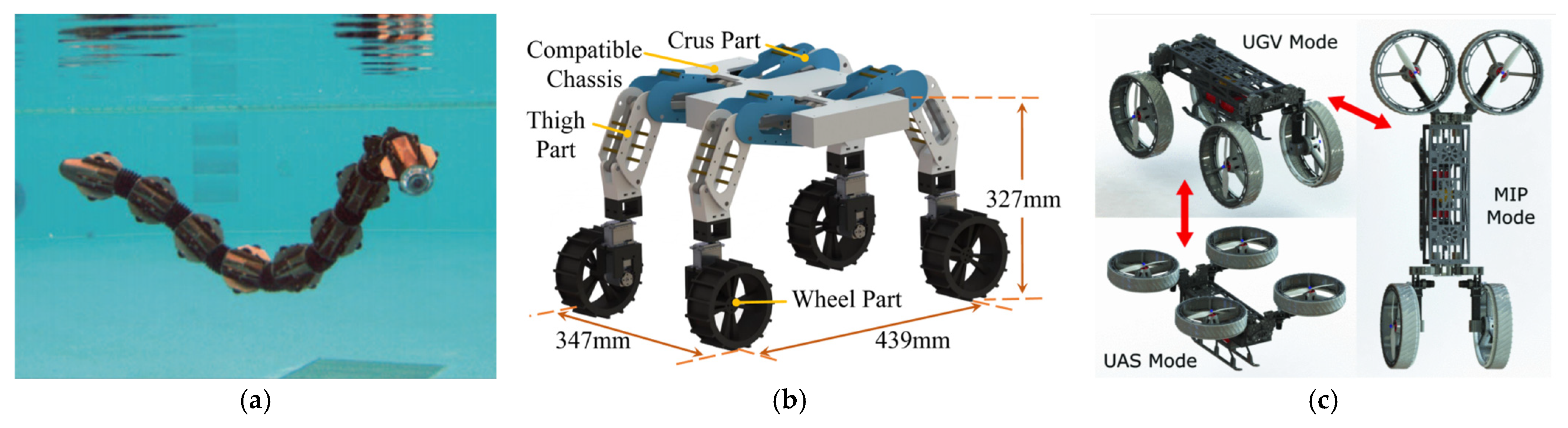
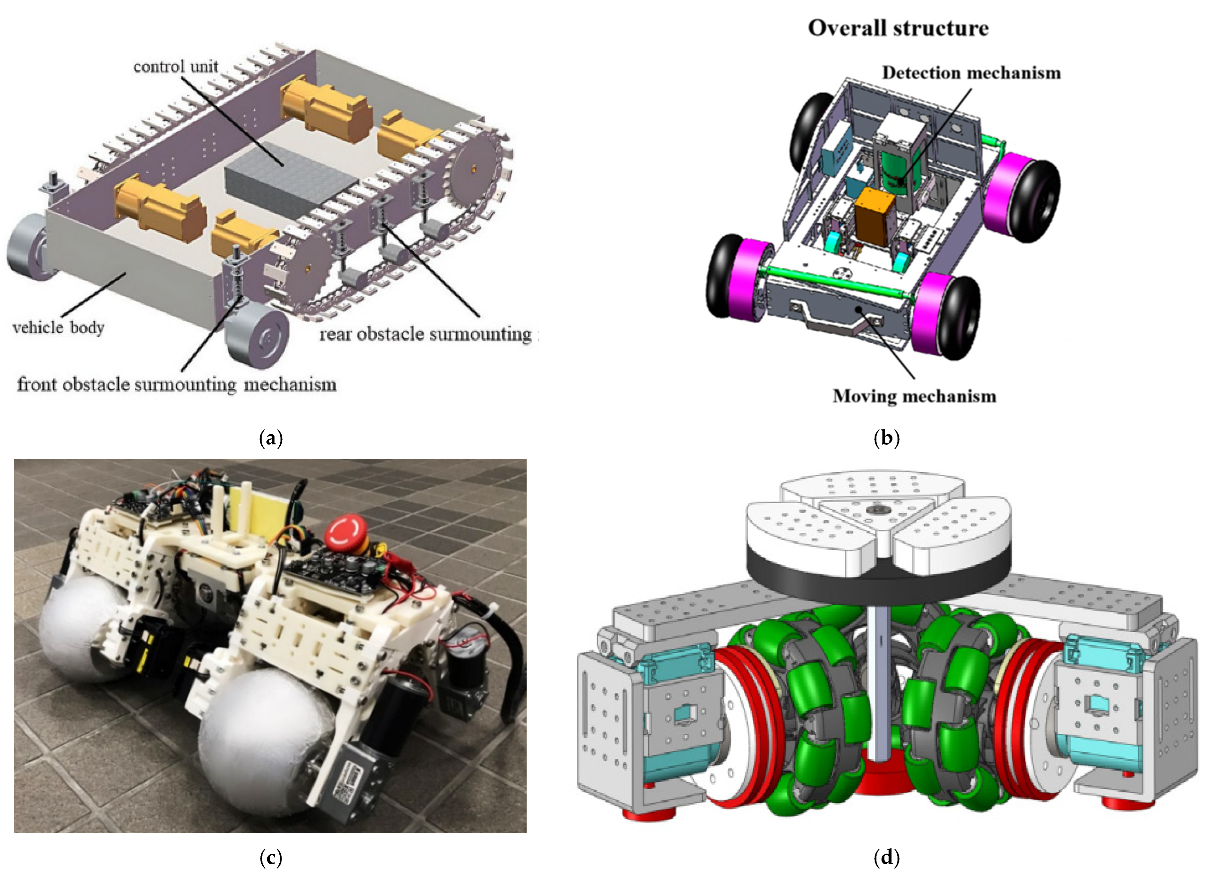
4.1. Diversification of the Motion Mechanism

Through an analysis of typical locomotion mechanisms—such as legged, wheeled, and tracked systems—and their applications in wall-climbing robots, it is evident that each mechanism has its own advantages and limitations. Legged systems offer superior obstacle-crossing capabilities, but often suffer from slow movement speeds and high energy consumption. In contrast, wheeled and tracked systems excel in dynamic stability and locomotion efficiency, yet face limitations when transitioning on walls or adapting to vertical terrains. To address specific environmental challenges, various novel mechanisms have been proposed. For example, snake-like multi-segment structures (Figure 25a) [166] and peristaltic soft-bodied mechanisms [167], with their excellent flexibility and deformability, are particularly suitable for locomotion tasks in narrow or confined spaces.
However, it is evident that robots based on single-mode locomotion mechanisms are typically tailored for specific terrain types and lack adaptability in complex or changing environments. To overcome this limitation, recent research has increasingly focused on integrating multiple locomotion mechanisms. By combining legged, wheeled, and tracked systems, these hybrid designs allow for complementary advantages across locomotion modes, significantly enhancing the environmental adaptability and operational reliability of wall-climbing robots [168,169,170]. For instance, in 2025, Ma proposed the LinkWheg wheel–leg hybrid robot (Figure 25b) [171], which incorporates a four-bar leg mechanism into a wheeled platform, combining the high mobility efficiency of wheels with the strong obstacle-surmounting capabilities of legs. This design optimizes the linkage configuration and load distribution, effectively enhancing structural stiffness and stability during obstacle traversal, enabling the robot to maneuver flexibly across complex surfaces such as gravel and sand.
Beyond hybrid mechanical designs, multi-modal reconfigurable systems (Figure 25c) [172] have also emerged as a promising approach to navigating dynamically complex terrains. A representative example is the Morphobot (M4) proposed by Sihite, a multi-modal mobile robot capable of seamlessly switching between unmanned ground vehicle (UGV), unmanned aerial system (UAS), and manipulator platform modes through morphological transformation and appendage reconfiguration. This integration of “morphological reconfiguration” and “multi-modal locomotion switching” provides valuable insight for the development of next-generation wall-climbing robots. According to task requirements, such robots may adopt soft-bodied or snake-like structures for confined spaces, or incorporate wheel–leg hybrid mechanisms to efficiently switch between high-speed mobility and stable climbing, thereby significantly enhancing their operational capabilities in unstructured and complex environments.
Figure 25. Diversification of the motion mechanism. (a) ACM-R5 amphibious (water–land) snake robot [166]. (b) The LinkWheg wheel-legged robot [171]. (c) Multi-modal reconfigurable systems [172].
Machines 13 00521 g025

4.2. Hybridization of Attachment Method

When wall-climbing robots are in operation, they are often required to carry additional equipment such as mechanical claws, ultra-high-pressure water spray guns, cameras, and sensors. This necessitates that the robots possess high mechanical stiffness while maintaining stable adhesion and detachment capabilities during movement. A comparison of various adhesion mechanisms reveals the following:
  • Negative pressure adhesion offers broad surface adaptability, but requires high wall airtightness.
  • Magnetic adhesion provides strong holding force, but is limited to ferromagnetic surfaces.
  • Electrostatic adhesion features a simple structure and is suitable for lightweight designs, yet its performance is significantly affected by environmental humidity.
  • Dry adhesion is adaptable to various environments, but its load capacity is limited, and the fabrication of adhesive footpads is often complex and costly.
  • Claw-spike attachment relies on mechanical interlocking with the surface, consuming little energy, but potentially damaging the wall.
To enhance environmental adaptability and enable reliable attachment on a wide range of surfaces (both smooth and rough), researchers have developed hybrid adhesion mechanisms. These include, for instance, disk–microspike composite structures [173], which combine the advantages of claw-hook interlocking and suction-based adhesion [174], or integrations of permanent magnets with negative pressure systems [175]. Such hybrid systems leverage the strengths of individual adhesion techniques to ensure stable and reliable operation of wall-climbing robots in diverse environments.
In addition to the challenge of unstable adhesion faced by wall-climbing robots operating at high altitudes on land, underwater climbing robots must also contend with multiple environmental difficulties, including high pressure, high humidity, and flow disturbances. As a result, relying on a single adhesion method is often insufficient to achieve long-term stable attachment. In recent years, researchers have begun to explore the integration of bioinspired underwater adhesion mechanisms with existing adhesion systems. Aquatic animals such as octopuses, clingfish, and remoras exhibit remarkable underwater adhesion capabilities [176,177,178]. For example, octopuses achieve efficient and controllable negative pressure adhesion through active muscular contraction of their suction cups, enabling attachment to complex surfaces; clingfish rely on abdominal suction structures combined with microstructured skin to generate high-sealing passive adhesion and surface conformity; and remoras utilize a combination of mechanical interlocking structures and suction chambers, allowing them to remain attached to their hosts even in high-speed water flow. Inspired by these mechanisms, some studies have preliminarily developed octopus-inspired muscular suction cups [179], which, when integrated with traditional vacuum or magnetic systems, can significantly improve the stability and task performance of climbing robots on complex underwater surfaces.

4.3. Intelligent Positioning and Navigation

Most current wall-climbing robots still rely on predefined control strategies for localization and path navigation, embedding a fixed set of logic into the controller to perform tasks such as adhesion, movement, and localization. These strategies are suitable for structured environments with simple terrains. Their advantages include simplicity of implementation, low computational resource consumption, and rapid engineering deployment. However, such approaches have limited adaptability to environmental changes and often depend on manual intervention or pre-programmed paths to complete tasks [180], making them inadequate for complex structural inspection or dynamic operation scenarios. To address this issue, an increasing number of wall-climbing robots are beginning to incorporate dynamic control strategies [181,182,183]. These strategies integrate real-time perception, decision-making, and adaptive regulation mechanisms into the control system, enabling the robot to plan paths online and adjust poses dynamically based on sensor-acquired environmental information, thus realizing a closed-loop intelligent control framework encompassing perception, planning, and execution.
In terms of localization, as mentioned above, externally measured positioning methods offer high accuracy and are less affected by the cumulative errors caused by the robot’s own motion. However, these methods suffer from high deployment costs and strong susceptibility to environmental interference. On the other hand, onboard sensor-based localization methods can utilize SLAM to simultaneously construct environment maps and achieve self-localization, offering greater flexibility. Nevertheless, they are still limited by hardware performance, and their localization errors tend to accumulate over time.
To overcome these challenges, future research on wall-climbing robots will focus on integrated application of multi-sensor fusion and adaptive cooperative mechanisms. On one hand, fusing multi-source data such as vision, inertial navigation, LiDAR, and ultrasound can enhance localization accuracy in outdoor and complex terrain environments, mitigating error accumulation caused by external factors or sensor limitations. On the other hand, improvements to traditional path planning algorithms are needed—for example, the enhanced Dijkstra-based planning method proposed by Wang et al. [151], which incorporates statistical modeling and error estimation of odometry errors during path planning to address path drift caused by localization uncertainty (e.g., GPS failure).
At the navigation level, intelligent development goes beyond the evolution of path planning algorithms, encompassing task semantics understanding and proactive behavioral decision-making. Future intelligent navigation systems will no longer be limited to static objectives such as “shortest path” or “minimum energy consumption.” Instead, they will consider multiple factors such as task priorities, structural risk distributions, and robot states to achieve task-driven and environment-responsive autonomous navigation. For instance, Xu et al. proposed a graph optimization-based UWB ranging localization method, which constructs trajectory smoothness and range constraints within a sliding window framework. This method effectively reduces dependence on kinematic models and concurrent multi-channel ranging, while enhancing robustness against measurement outliers. It has demonstrated excellent vertical localization performance across various scenarios and is particularly suitable for stable autonomous navigation of wall-climbing robots in structurally complex or high-altitude environments [184].

5. Conclusions

In today’s society, wall-climbing robots have demonstrated significant advantages in practical applications such as high-altitude cleaning, ship hull descaling, and aircraft wing inspection, while also showing great potential in emerging fields like interstellar exploration and crater traversal. This paper systematically summarizes the core attachment principles employed in wall-climbing robots. For major attachment methods—including vacuum adhesion, magnetic adhesion, electrostatic adhesion, dry adhesion, and claw-spine attachment—it analyzes their physical characteristics, advantages, limitations, and scalability in relation to robot size and structural design.
To overcome the inherent physical and performance limitations of single attachment methods, hybrid attachment strategies are increasingly adopted to achieve complementary performance. For example, in magnetic adhesion, the combination of permanent magnets and electromagnets—known as electro-permanent magnetism or mixed-excitation adhesion—offers a more flexible and controllable solution. Similarly, hybrid schemes such as the integration of claw-hook interlocking with suction adhesion, or the fusion of permanent magnets with vacuum systems, effectively enhance adaptability to complex and variable environments.
However, such hybrid approaches introduce new challenges in mechanical structure design and material integration. Moreover, simply increasing the number of joints to enhance mobility often leads to higher control complexity and energy consumption, reducing endurance. Therefore, future designs should emphasize the co-optimization of motion and attachment mechanisms, promoting the integration of multiple locomotion modes to achieve multimodal, efficient, and stable wall-climbing performance.
Beyond mechanical design, this paper also reviews common localization and path planning algorithms for wall-climbing robots, comparing their strengths and weaknesses. Graph search algorithms (e.g., A* and Dijkstra) perform well in structured environments, but struggle with sudden environmental changes. Sampling/randomized algorithms (e.g., RRT and PRM) are suited for high-degree-of-freedom, constrained legged, or bio-inspired robots, but suffer from path smoothness issues. Feedback-based planning methods (e.g., artificial potential fields and D* algorithms) are effective for highly dynamic environments, but are prone to local minima.
In summary, the continuous advancement of integrated mechanical design, intelligent control strategies, and adaptive attachment technologies will be key to unlocking the full potential of wall-climbing robots across industrial maintenance, environmental monitoring, and scientific exploration.

Author Contributions

S.L.: methodology, literature collation, writing—original draft. Z.W. and A.S.: writing—review and editing. J.G.: chart drawing and visualization. Y.D. and J.L.: supervision and conceptualization. All authors have read and agreed to the published version of the manuscript.

Funding

This research was funded by the National Natural Science Foundation of China, Grant number 62103197, and the Postgraduate Research & Practice Innovation Program of Jiangsu Province, Grant number SJCX25_0533.

Informed Consent Statement

Not applicable.

Data Availability Statement

Not applicable.

Acknowledgments

The authors are grateful for the support by the National Natural Science Foundation of China and the Postgraduate Research & Practice Innovation Program of Jiangsu Province.

Conflicts of Interest

The authors declare no conflicts of interest.

References

  1. Kalra, L.P.; Gu, J.; Meng, M. A Wall Climbing Robot for Oil Tank Inspection. In Proceedings of the 2006 IEEE International Conference on Robotics and Biomimetics, Kunming, China, 17–20 December 2006; IEEE: New York, NY, USA, 2006; pp. 1523–1528. [Google Scholar]
  2. Yi, Z.; Gong, Y.; Wang, Z.; Liu, Q. Development of a Wall Climbing Robot for Ship Rust Removal. In Proceedings of the 2009 International Conference on Mechatronics and Automation, Changchun, China, 9–12 August 2009; IEEE: New York, NY, USA, 2009; pp. 4610–4615. [Google Scholar]
  3. Yi, Z.; Mi, S.; Feng, B.; Liu, Q. A Large Surface Spraying Technical Analysis of Ship Shell with Wall Climbing Robot in China. Available online: https://ssrn.com/abstract=4674023 (accessed on 5 June 2025).
  4. Sattar, T.P. Wall Climbing Crawlers for Nondestructive Testing; American Society for Nondestructive Testing: Columbus, OH, USA, 2000. [Google Scholar]
  5. Berns, K.; Hillenbrand, C. A Climbing Robot Based on Under Pressure Adhesion for the Inspection of Concrete Walls. In Proceedings of the ISR 2004—35th International Symposium on Robotics, Paris, France, 23–26 March 2004; pp. 1–6. [Google Scholar]
  6. Eich, M.; Vögele, T. Design and Control of a Lightweight Magnetic Climbing Robot for Vessel Inspection. In Proceedings of the 2011 19th Mediterranean Conference on Control & Automation (MED), Corfu, Greece, 20–23 June 2011; IEEE: New York, NY, USA, 2011; pp. 1200–1205. [Google Scholar]
  7. Liu, R.; Chen, R.; Shen, H.; Ma, L.; Feng, J. Wall Climbing Robot Using Electrostatic Adhesion Force Generated by Flexible Interdigital Electrodes. Int. J. Adv. Robot. Syst. 2013, 10, 36. [Google Scholar] [CrossRef]
  8. Liu, Y.; Shin, M.; Jeong, K.; Park, Y. Dry Adhesion Optimization Design for a Wall-Climbing Robot Based on Experiment. In Proceedings of the 2014 11th International Conference on Ubiquitous Robots and Ambient Intelligence (URAI), Kuala Lumpur, Malaysia, 12–15 November 2014; IEEE: New York, NY, USA, 2014; pp. 216–219. [Google Scholar]
  9. Hawkes, E.W.; Ulmen, J.; Esparza, N.; Spenko, M.; Cutkosky, M.R. Scaling Walls: Applying Dry Adhesives to the Real World. In Proceedings of the 2011 IEEE/RSJ International Conference on Intelligent Robots and Systems, San Francisco, CA, USA, 25–30 September 2011; IEEE: New York, NY, USA, 2011; pp. 5100–5106. [Google Scholar]
  10. Liu, Y.; Lim, B.; Lee, J.W.; Park, S. Steerable Dry-Adhesive Linkage-Type Wall-Climbing Robot. Mech. Mach. Theory 2020, 153, 103987. [Google Scholar] [CrossRef]
  11. Miyake, T.; Ishihara, H.; Yoshimura, M. Basic Studies on Wet Adhesion System for Wall Climbing Robots. In Proceedings of the 2007 IEEE/RSJ International Conference on Intelligent Robots and Systems (IROS), San Diego, CA, USA, 29 October–2 November 2007; IEEE: New York, NY, USA, 2007; pp. 1920–1925. [Google Scholar]
  12. Xu, F.; Wang, B.; Shen, J.; Zhao, H.; Li, M. Design and Realization of the Claw Gripper System of a Climbing Robot. J. Intell. Robot. Syst. 2018, 89, 301–317. [Google Scholar] [CrossRef]
  13. Li, M.; Mao, A.; Guan, Q.; Saiz, E. Nature-Inspired Adhesive Systems. Chem. Soc. Rev. 2024, 53, 8240–8305. [Google Scholar] [CrossRef] [PubMed]
  14. Yang, W.; Yang, C.; Zhang, R.; He, X. A Novel Worm-Inspired Wall Climbing Robot with Sucker-Microspine Composite Structure. In Proceedings of the 2018 3rd International Conference on Advanced Robotics and Mechatronics (ICARM), Singapore, 18–20 July 2018; IEEE: New York, NY, USA, 2018; pp. 744–749. [Google Scholar]
  15. Simões, S. High-Performance Advanced Composites in Multifunctional Material Design: State of the Art, Challenges, and Future Directions. Materials 2024, 17, 5997. [Google Scholar] [CrossRef]
  16. Rich, S.I.; Wood, R.J.; Majidi, C. Untethered Soft Robotics. Nat. Electron. 2018, 1, 102–112. [Google Scholar] [CrossRef]
  17. Pukánszky, B.; Fekete, E. Adhesion and Surface Modification. In Mineral Fillers in Thermoplastics I: Raw Materials and Processing; Springer: Berlin/Heidelberg, Germany, 1999; pp. 109–153. [Google Scholar]
  18. Guangqing, C.; Lei, Z.; Jinze, X.; Zhu, J. Analysis and Future Prospects of Adsorption Techniques Employed by Wall-Climbing. Int. J. Adv. Robot. Syst. 2024, 21, 17298806241279611. [Google Scholar] [CrossRef]
  19. Zhu, J.; Zhu, Y.; Zhang, P. Review of Advancements in Wall Climbing Robot Techniques. Frankl. Open 2024, 8, 100148. [Google Scholar] [CrossRef]
  20. Brusell, A.; Andrikopoulos, G.; Nikolakopoulos, G. Novel Considerations on the Negative Pressure Adhesion of Electric Ducted Fans: An Experimental Study. In Proceedings of the 2017 25th Mediterranean Conference on Control and Automation (MED), Valletta, Malta, 3–6 July 2017; IEEE: New York, NY, USA, 2017; pp. 1404–1409. [Google Scholar]
  21. Fang, Y.; Wang, S.; Bi, Q.; Zhang, L. Design and Technical Development of Wall-Climbing Robots: A Review. J. Bionic Eng. 2022, 19, 877–901. [Google Scholar] [CrossRef]
  22. Kang, T.; Kim, H.; Choi, H. Realtime Perception with Infrared Scanner for Navigation of Quadruped Walking and Climbing Robot. In Proceedings of the 2004 IEEE/RSJ International Conference on Intelligent Robots and Systems (IROS), Sendai, Japan, 28 September–2 October 2004; IEEE: New York, NY, USA, 2004; Volume 3, pp. 2550–2555. [Google Scholar]
  23. Xue, C.; Du, Q.; Ma, W.; Geng, Y. Research on Motion Control of Bionic Sucker Inchworm Robot Based on MPC. IEEE Access 2023, 11, 92943–92958. [Google Scholar] [CrossRef]
  24. Shi, X.; Xu, L.; Xu, H.; Yang, X.; Feng, B. A 6-DOF Humanoid Wall-Climbing Robot with Flexible Adsorption Feet Based on Negative Pressure Suction. Mechatronics 2022, 87, 102889. [Google Scholar] [CrossRef]
  25. Guan, Y.; Zhu, H.; Wu, W.; Li, Y. A Modular Biped Wall-Climbing Robot with High Mobility and Manipulating Function. IEEE/ASME Trans. Mechatron. 2012, 18, 1787–1798. [Google Scholar] [CrossRef]
  26. Ito, K.; Yoshizawa, K. Uraraka VI: Multi-Legged Robot with Suckers to Climb Walls and Pipes. Artif. Life Robot. 2022, 27, 834–841. [Google Scholar] [CrossRef]
  27. Shang, J.; Sattar, T.; Chen, S.; Bridge, B. Design of a Climbing Robot for Inspecting Aircraft Wings and Fuselage. Ind. Robot 2007, 34, 495–502. [Google Scholar] [CrossRef]
  28. Rosyid, A.; Stefanini, C.; El-Khasawneh, B. A Reconfigurable Parallel Robot for On-Structure Machining of Large Structures. Robotics 2022, 11, 110. [Google Scholar] [CrossRef]
  29. Rosyid, A.; Stefanini, C.; El-Khasawneh, B. A novel walking parallel robot for on-structure three-axis machining of large structures. J. Mech. Robot. 2023, 15, 061016. [Google Scholar] [CrossRef]
  30. Rosyid, A.; El-Khasawneh, B. A Large-Scale Suction-Based Climbing Parallel Robot for Wall Painting Application. In Proceedings of the 2024 IEEE International Conference on Robotics and Automation (ICRA), Yokohama, Japan, 13–17 May 2024; IEEE: New York, NY, USA, 2024. [Google Scholar]
  31. Ge, D.; Ren, C.; Matsuno, T.; Ma, S. Guide Rail Design for a Passive Suction Cup Based Wall-Climbing Robot. In Proceedings of the 2016 IEEE/RSJ International Conference on Intelligent Robots and Systems (IROS), Daejeon, Republic of Korea, 9–14 October 2016; IEEE: New York, NY, USA, 2016; pp. 5776–5781. [Google Scholar]
  32. Lee, G.; Kim, H.; Seo, K.; Kim, J.; Kim, H.S. MultiTrack: A Multi-Linked Track Robot with Suction Adhesion for Climbing and Transition. Robot. Auton. Syst. 2015, 72, 207–216. [Google Scholar] [CrossRef]
  33. Huang, H.; Wang, Z.; Cheng, S.; Li, C. Optimized Design of the Main Structure of a Wall-Climbing Robot for Bridge Detection Based on Negative Pressure Adhesion. J. South China Univ. Technol. (Nat. Sci. Ed.) 2023, 51, 21–33. [Google Scholar] [CrossRef]
  34. Yang, L.; Li, B.; Feng, J.; Yang, G.; Chang, Y.; Jiang, B.; Xiao, J. Automated Wall-Climbing Robot for Concrete Construction Inspection. J. Field Robot. 2023, 40, 110–129. [Google Scholar] [CrossRef]
  35. Longo, D.; Muscato, G. The Alicia/sup 3/Climbing Robot: A Three-Module Robot for Automatic Wall Inspection. IEEE Robot. Autom. Mag. 2006, 13, 42–50. [Google Scholar] [CrossRef]
  36. Fang, Y.; Wang, S.; Cui, D.; Bi, Q.; Jiang, R.; Yan, C. Design and Optimization of Wall-Climbing Robot Impeller by Genetic Algorithm Based on Computational Fluid Dynamics and Kriging Model. Sci. Rep. 2022, 12, 9571. [Google Scholar] [CrossRef] [PubMed]
  37. Yuan, C.; Chang, Y.; Song, Y.; Lin, S.; Jing, F. Design and Analysis of a Negative Pressure Wall-Climbing Robot with an Omnidirectional Characteristic for Cylindrical Wall. Robotica 2024, 42, 2226–2242. [Google Scholar] [CrossRef]
  38. Zhao, Y.; Yang, C. Development of an Underwater Cleaning Robot with Vortex Suction Mechanism. In Proceedings of the 2022 3rd International Conference on Robotics Systems and Vehicle Technology, Singapore, 22–24 July 2022. [Google Scholar]
  39. Tang, Q.; Du, Y.; Ding, M.; Zhang, S.; Zhao, Q.; Hu, S.; Wang, G. Study on the Performance of Vortex Suction Cup for an Underwater Inspection Robot. Ocean Eng. 2024, 300, 117462. [Google Scholar] [CrossRef]
  40. Shin, J.U.; Kim, D.; Kim, J.H.; Myung, H. Micro-Aerial Vehicle Type Wall-Climbing Robot Mechanism for Structural Health Monitoring. In Sensors and Smart Structures Technologies for Civil, Mechanical, and Aerospace Systems 2013; SPIE: Bellingham, WA, USA, 2013; Volume 8692, pp. 363–369. [Google Scholar]
  41. Nishimura, Y.; Mochiyama, H.; Yamaguchi, T. Propeller-Type Wall-Climbing Robot for Visual and Hammering Inspection of Concrete Surfaces. IEEE Access 2024, 12, 70963–70972. [Google Scholar] [CrossRef]
  42. Liang, P.; Gao, X.; Zhang, Q.; Gao, R.; Li, M.; Xu, Y.; Zhu, W. Design and Stability Analysis of a Wall-Climbing Robot Using Propulsive Force of Propeller. Symmetry 2020, 13, 37. [Google Scholar] [CrossRef]
  43. Alkalla, M.G.; Fanni, M.A.; Mohamed, A.F.; Hashimoto, S.; Sawada, H.; Miwa, T.; Hamed, A. EJBot-II: An Optimized Skid-Steering Propeller-Type Climbing Robot with Transition Mechanism. Adv. Robot. 2019, 33, 1042–1059. [Google Scholar] [CrossRef]
  44. Vega-Heredia, M.; Mohan, R.E.; Wen, T.Y.; Siti’Aisyah, J.; Vengadesh, A.; Ghanta, S.; Vinu, S. Design and Modelling of a Modular Window Cleaning Robot. Autom. Constr. 2019, 103, 268–278. [Google Scholar] [CrossRef]
  45. Kawasaki, K.; Motegi, Y.; Zhao, M.; Okada, K.; Inaba, M. Dual Connected Bi-Copter with New Wall Trace Locomotion Feasibility That Can Fly at Arbitrary Tilt Angle. In Proceedings of the 2015 IEEE/RSJ International Conference on Intelligent Robots and Systems (IROS), Hamburg, Germany, 28 September–2 October 2015; IEEE: New York, NY, USA, 2015; pp. 524–531. [Google Scholar]
  46. Wu, M.; Pan, G.; Zhang, T.; Chen, S.; Zhuang, F.; Yan-zheng, Z. Design and Optimal Research of a Non-Contact Adjustable Magnetic Adhesion Mechanism for a Wall-Climbing Welding Robot. Int. J. Adv. Robot. Syst. 2013, 10, 63. [Google Scholar] [CrossRef]
  47. Kratt, K.; Badilita, V.; Burger, T.; Korvink, J.G.; Wallrabe, U. A Fully MEMS-Compatible Process for 3D High Aspect Ratio Micro Coils Obtained with an Automatic Wire Bonder. J. Micromech. Microeng. 2009, 20, 015021. [Google Scholar] [CrossRef]
  48. Sun, J.; Tao, Z.; Li, H.; Zhu, K.; Wang, D.; Wu, H.; Xu, T. A MEMS Voice Coil Motor with a 3D Solenoid Coil. In Proceedings of the 2021 IEEE 16th International Conference on Nano/Micro Engineered and Molecular Systems (NEMS), Xiamen, China, 25–29 April 2021; IEEE: New York, NY, USA, 2021; pp. 1745–1748. [Google Scholar]
  49. Cai, J.; He, K.; Fang, H.; Chen, H.; Hu, S.; Zhou, W. The Design of Permanent-Magnetic Wheeled Wall-Climbing Robot. In Proceedings of the 2017 IEEE International Conference on Information and Automation (ICIA), Macau, China, 18–20 July 2017; IEEE: New York, NY, USA, 2017; pp. 604–608. [Google Scholar]
  50. Xu, M.; Xue, S.; Wang, Q.; He, S.; Deng, R.; Li, Z.; Li, R. Design and Analysis of Wheel-Tracked Composite Magnetic Adhesion Wall-Climbing Robot. Ind. Robot Int. J. Robot. Res. Appl. 2024, 52, 94–105. [Google Scholar] [CrossRef]
  51. Zhang, X.; Zhang, M.; Jiao, S.; Sun, L.; Li, M. Design and Optimization of the Wall Climbing Robot for Magnetic Particle Detection of Ship Welds. J. Mar. Sci. Eng. 2024, 12, 610. [Google Scholar] [CrossRef]
  52. Eto, H.; Asada, H.H. Development of a Wheeled Wall-Climbing Robot with a Shape-Adaptive Magnetic Adhesion Mechanism. In Proceedings of the 2020 IEEE International Conference on Robotics and Automation (ICRA), Paris, France, 31 May–31 August 2020; IEEE: New York, NY, USA, 2020; pp. 9329–9335. [Google Scholar]
  53. Tavakoli, M.; Viegas, C.; Marques, L.; Pires, J.N.; De Almeida, A.T. OmniClimbers: Omni-directional Magnetic Wheeled Climbing Robots for Inspection of Ferromagnetic Structures. Robot. Auton. Syst. 2013, 61, 997–1007. [Google Scholar] [CrossRef]
  54. Zhang, Y.; Guan, E.; Li, P.; Zhao, Y. An Automated Nondestructive Testing System for the Surface of Pressure Pipeline Welds. J. Field Robot. 2023, 40, 1927–1944. [Google Scholar] [CrossRef]
  55. Park, C.; Bae, J.; Ryu, S.; Lee, J.; Seo, T. R-track: Separable Modular Climbing Robot Design for Wall-to-Wall Transition. IEEE Robot. Autom. Lett. 2021, 6, 1036–1042. [Google Scholar] [CrossRef]
  56. Zhao, J.; Zhang, Y.; Bi, X.; Yan, C.; Dong, Y. Optimum Design of Magnetic Adhesion Structure and Machine Performance Test for Sand Blasting and Rust-Removing Wall-Climbing Robot. J. China Univ. Pet. 2020, 44, 94–99. [Google Scholar]
  57. Hu, J.; Han, X.; Tao, Y.; Feng, S. A Magnetic Crawler Wall-Climbing Robot with Capacity of High Payload on the Convex Surface. Robot. Auton. Syst. 2022, 148, 103907. [Google Scholar] [CrossRef]
  58. Park, G.; Rodrigue, H. Soft Climbing Robot with Magnetic Feet for Multimodal Locomotion. Sci. Rep. 2023, 13, 8377. [Google Scholar] [CrossRef]
  59. Khan, M.B.; Chuthong, T.; Do, C.D.; Thor, M.; Billeschou, P.; Larsen, J.C.; Manoonpong, P. iCrawl: An Inchworm-Inspired Crawling Robot. IEEE Access 2020, 8, 200655–200668. [Google Scholar] [CrossRef]
  60. Lin, T.H.; Putranto, A.; Chen, P.H.; Teng, Y.Z.; Chen, L. High-Mobility Inchworm Climbing Robot for Steel Bridge Inspection. Autom. Constr. 2023, 152, 104905. [Google Scholar] [CrossRef]
  61. Hong, S.; Um, Y.; Park, J.; Park, H.W. Agile and Versatile Climbing on Ferromagnetic Surfaces with a Quadrupedal Robot. Sci. Robot. 2022, 7, eadd1017. [Google Scholar] [CrossRef]
  62. Hong, X.; Chen, Y. Development of Innovative Wall-Climbing Robot with Electromagnetic Absorption. Mech. Sci. Technol. 2021, 40, 337–343. [Google Scholar]
  63. Tarapongnivat, K.; Janna, R.; Nantareekurn, W.; Ausrivong, W.; Srisuchinnawong, A.; Asawalertsak, N.; Manoonpong, P. Hybrid Omnidirectional Wheeled Climbing Robot with an Electromagnet for Inspection. In Proceedings of the Climbing and Walking Robots Conference, Florianópolis, Brazil, 2–4 October 2023; Springer: Cham, Switzerland, 2023; pp. 82–87. [Google Scholar]
  64. Peidró, A.; Tavakoli, M.; Marín, J.M.; Reinoso, Ó. Design of Compact Switchable Magnetic Grippers for the HyReCRo Structure-Climbing Robot. Mechatronics 2019, 59, 199–212. [Google Scholar] [CrossRef]
  65. Wang, B.; Li, P.; Li, P.; Zhang, L.; Guan, E.; Liu, X.; Zhao, Y. Development of a Wheeled Wall-Climbing Robot with an Internal Corner Wall Adaptive Magnetic Adhesion Mechanism. J. Field Robot. 2024, 42, 97–114. [Google Scholar] [CrossRef]
  66. Wang, G.; Li, W.; Che, H. Design and Analysis of Anti-Overturning Mechanism for Magnetic Wall-Climbing Robot. J. Mech. Sci. Technol. 2024, 38, 379–387. [Google Scholar] [CrossRef]
  67. Song, W.; Jiang, H.; Wang, T.; Ji, D.; Zhu, S. Design of Permanent Magnetic Wheel-Type Adhesion-Locomotion System for Water-Jetting Wall-Climbing Robot. Adv. Mech. Eng. 2018, 10, 1687814018787378. [Google Scholar] [CrossRef]
  68. Guerrero, J.M.; De Vicuna, L.G.; Uceda, J. Uninterruptible Power Supply Systems Provide Protection. IEEE Ind. Electron. Mag. 2007, 1, 28–38. [Google Scholar] [CrossRef]
  69. Shi, J.; Xu, Y.; Liao, M.; Guo, S.; Li, Y.; Ren, L.; Tang, Y. Integrated Design Method for Superconducting Magnetic Energy Storage Considering the High Frequency Pulse Width Modulation Pulse Voltage on Magnet. Appl. Energy 2019, 248, 1–17. [Google Scholar] [CrossRef]
  70. Shi, B.; Agnihotri, M.V.; Chen, S.H.; Black, R.; Singer, S.J. Polarization charge: Theory and applications to aqueous interfaces. J. Chem. Phys. 2016, 144, 164702. [Google Scholar] [CrossRef]
  71. Feng, P.X.L.; Young, D.J.; Zorman, C.A. MEMS/NEMS Devices and Applications. In Springer Handbook of Nanotechnology, 3rd ed.; Springer: Berlin/Heidelberg, Germany, 2017; pp. 395–429. [Google Scholar]
  72. Cao, J.; Qin, L.; Liu, J.; Ren, Q.; Foo, C.C.; Wang, H.; Zhu, J. Untethered Soft Robot Capable of Stable Locomotion Using Soft Electrostatic Actuators. Extreme Mech. Lett. 2018, 21, 9–16. [Google Scholar] [CrossRef]
  73. Qin, L.; Liang, X.; Huang, H.; Chui, C.K.; Yeow, R.C.H.; Zhu, J. A Versatile Soft Crawling Robot with Rapid Locomotion. Soft Robot. 2019, 6, 455–467. [Google Scholar] [CrossRef]
  74. Hu, Q.; Li, J.; Dong, E.; Sun, D. Soft Scalable Crawling Robots Enabled by Programmable Origami and Electrostatic Adhesion. IEEE Robot. Autom. Lett. 2023, 8, 2365–2372. [Google Scholar] [CrossRef]
  75. Gu, G.; Zou, J.; Zhao, R.; Zhao, X.; Zhu, X. Soft Wall-Climbing Robots. Sci. Robot. 2018, 3, eaat2874. [Google Scholar] [CrossRef] [PubMed]
  76. Chen, R.; Liu, R.; Chen, J.; Zhang, J. A Gecko Inspired Wall-Climbing Robot Based on Electrostatic Adhesion Mechanism. In Proceedings of the 2013 IEEE International Conference on Robotics and Biomimetics (ROBIO), Shenzhen, China, 12–14 December 2013; IEEE: New York, NY, USA, 2013; pp. 396–401. [Google Scholar]
  77. De Rivaz, S.D.; Goldberg, B.; Doshi, N.; Jayaram, K.; Zhou, J.; Wood, R.J. Inverted and Vertical Climbing of a Quadrupedal Microrobot Using Electroadhesion. Sci. Robot. 2018, 3, eaau3038. [Google Scholar] [CrossRef]
  78. Yamamoto, A.; Nakashima, T.; Higuchi, T. Wall Climbing Mechanisms Using Electrostatic Attraction Generated by Flexible Electrodes. In Proceedings of the 2007 International Symposium on Micro-NanoMechatronics and Human Science, Nagoya, Japan, 11–14 November 2007; IEEE: New York, NY, USA, 2007; pp. 389–394. [Google Scholar]
  79. Wang, L. Research on a Tracked Wall-Climbing Robot Based on a Bionic Compliant Claw-Spike Structure. Master’s Thesis, South China University of Technology, Guangzhou, China, 2012. [Google Scholar]
  80. Prahlad, H.; Pelrine, R.; Stanford, S.; Marlow, J.; Kornbluh, R. Electroadhesive Robots—Wall Climbing Robots Enabled by a Novel, Robust, and Electrically Controllable Adhesion Technology. In Proceedings of the 2008 IEEE International Conference on Robotics and Automation, Pasadena, CA, USA, 19–23 May 2008; IEEE: New York, NY, USA, 2008; pp. 3028–3033. [Google Scholar]
  81. Chen, R.; Liu, R.; Shen, H. Design of a Double-Tracked Wall Climbing Robot Based on Electrostatic Adhesion Mechanism. In Proceedings of the 2013 IEEE Workshop on Advanced Robotics and Its Social Impacts, Tokyo, Japan, 7–9 November 2013; IEEE: New York, NY, USA, 2013; pp. 212–217. [Google Scholar]
  82. Wang, H.; Yamamoto, A. Analyses and Solutions for the Buckling of Thin and Flexible Electrostatic Inchworm Climbing Robots. IEEE Trans. Robot. 2017, 33, 889–900. [Google Scholar] [CrossRef]
  83. Wang, H.; Yamamoto, A.; Higuchi, T. Electrostatic-motor-driven electroadhesive robot. In Proceedings of the 2012 IEEE/RSJ International Conference on Intelligent Robots and Systems, Algarve, Portugal, 7–12 October 2012; IEEE: New York, NY, USA, 2012; pp. 914–919. [Google Scholar]
  84. Fang, G.; Cheng, J. Advances in climbing robots for vertical structures in the past decade: A review. Biomimetics 2023, 8, 47. [Google Scholar] [CrossRef]
  85. Mao, J.B.; Qin, L.; Zhang, W.X.; Xie, L.; Wang, Y. Modeling and analysis of electrostatic adhesion force for climbing robot on dielectric wall materials. Eur. Phys. J. Appl. Phys. 2015, 69, 11003. [Google Scholar] [CrossRef]
  86. Pugno, N.M.; Lepore, E. Living Tokay Geckos display adhesion times following Weibull statistics. J. Adhes. 2008, 84, 947–960. [Google Scholar] [CrossRef]
  87. Bullock, J.M.R.; Drechsler, P.; Federle, W. Comparison of smooth and hairy attachment pads in insects: Friction, adhesion and mechanisms for direction-dependence. J. Exp. Biol. 2008, 211, 3333–3343. [Google Scholar] [CrossRef]
  88. Guo, C.; Sun, J.R.; Ge, Y.B.; Wang, W.; Wang, D.; Dai, Z. Biomechanism of adhesion in gecko setae. Sci. China Life Sci. 2012, 55, 181–187. [Google Scholar] [CrossRef]
  89. Persson, B.N.J. On the mechanism of adhesion in biological systems. J. Chem. Phys. 2003, 118, 7614–7621. [Google Scholar] [CrossRef]
  90. Huber, G.; Gorb, S.N.; Hosoda, N.; Spolenak, R.; Arzt, E. Influence of surface roughness on gecko adhesion. Acta Biomater. 2007, 3, 607–610. [Google Scholar] [CrossRef]
  91. Pugno, N.M.; Lepore, E. Observation of optimal gecko’s adhesion on nanorough surfaces. Biosystems 2008, 94, 218–222. [Google Scholar] [CrossRef] [PubMed]
  92. Autumn, K.; Dittmore, A.; Santos, D.; Spenko, M.; Cutkosky, M. Frictional adhesion: A new angle on gecko attachment. J. Exp. Biol. 2006, 209, 3569–3579. [Google Scholar] [CrossRef]
  93. Israelachvili, J.N. Intermolecular and Surface Forces, 3rd ed.; Academic Press: London, UK, 2011. [Google Scholar]
  94. Haomachai, W.; Shao, D.; Wang, W.; Ji, A.; Dai, Z.; Manoonpong, P. Lateral undulation of the bendable body of a gecko-inspired robot for energy-efficient inclined surface climbing. IEEE Robot. Autom. Lett. 2021, 6, 7917–7924. [Google Scholar] [CrossRef]
  95. Duan, J.; Wang, B.; Ji, B.; Sun, W.; Wang, Z.; Dai, Z. Control Strategy of Stable Climbing Mechanics for Gecko-Inspired Robot on Vertical Arc Surface. IEEE Instrum. Meas. Mag. 2023, 26, 48–56. [Google Scholar] [CrossRef]
  96. Menon, C.; Li, Y.; Sameoto, D.; Martens, C. Abigaille-I: Towards the development of a spider-inspired climbing robot for space use. In Proceedings of the 2008 2nd IEEE RAS & EMBS International Conference on Biomedical Robotics and Biomechatronics, Scottsdale, AZ, USA, 19–22 October 2008; IEEE: New York, NY, USA, 2008; pp. 384–389. [Google Scholar]
  97. Hawkes, E.W.; Christensen, D.L.; Cutkosky, M.R. Vertical dry adhesive climbing with a 100× bodyweight payload. In Proceedings of the 2015 IEEE International Conference on Robotics and Automation (ICRA), Seattle, WA, USA, 26–30 May 2015; IEEE: New York, NY, USA, 2015; pp. 3762–3769. [Google Scholar]
  98. Dai, Z.; Zhang, H.; Li, H. Biomimetics of gecko locomotion: From biology to engineering. In Proceedings of the 2009 ASME/IFToMM International Conference on Reconfigurable Mechanisms and Robots, London, UK, 22–24 June 2009; IEEE: New York, NY, USA, 2009; pp. 464–468. [Google Scholar]
  99. Xiao, J.; Hao, L.; Xu, H.; Zhang, X.; Li, X.; Li, Z. MST-Q: Micro suction tape quadruped robot with high payload capacity. IEEE Robot. Autom. Lett. 2023, 8, 7304–7311. [Google Scholar] [CrossRef]
  100. Custodio, J.A.; Wang, Y. A spoke-wheel based wall-climbing robot. In Proceedings of the 2008 IEEE Conference on Robotics, Automation and Mechatronics, Chengdu, China, 21–24 September 2008; IEEE: New York, NY, USA, 2008; pp. 456–461. [Google Scholar]
  101. Gorb, S.N.; Sinha, M.; Peressadko, A.; Daltorio, K.A.; Quinn, R.D. Insects did it first: A micropatterned adhesive tape for robotic applications. Bioinspir. Biomim. 2007, 2, S117. [Google Scholar] [CrossRef]
  102. Murphy, M.P.; Sitti, M. Waalbot: An agile small-scale wall-climbing robot utilizing dry elastomer adhesives. IEEE/ASME Trans. Mechatron. 2007, 12, 330–338. [Google Scholar] [CrossRef]
  103. Daltorio, K.A.; Gorb, S.; Peressadko, A.; Horchler, A.D.; Ritzmann, R.E.; Quinn, R.D. A robot that climbs walls using micro-structured polymer feet. In Climbing and Walking Robots, Proceedings of the 8th International Conference on Climbing and Walking Robots and the Support Technologies for Mobile Machines (CLAWAR 2005), London, UK, 13–15 September 2005; Springer: Berlin/Heidelberg, Germany, 2006; pp. 131–138. [Google Scholar]
  104. Unver, O.; Sitti, M. Tankbot: A palm-size, tank-like climbing robot using soft elastomer adhesive treads. Int. J. Robot. Res. 2010, 29, 1761–1777. [Google Scholar] [CrossRef]
  105. Seo, T.; Sitti, M. Tank-like module-based climbing robot using passive compliant joints. IEEE/ASME Trans. Mechatron. 2012, 18, 397–408. [Google Scholar] [CrossRef]
  106. Krahn, J.; Liu, Y.; Sadeghi, A.; Menon, C. A tailless timing belt climbing platform utilizing dry adhesives with mushroom caps. Smart Mater. Struct. 2011, 20, 115021. [Google Scholar] [CrossRef]
  107. Autumn, K.; Sitti, M.; Liang, Y.A.; Peattie, A.M.; Hansen, W.R.; Sponberg, S. Evidence for van der Waals adhesion in gecko setae. Proc. Natl. Acad. Sci. USA 2002, 99, 12252–12256. [Google Scholar] [CrossRef] [PubMed]
  108. Huber, G.; Mantz, H.; Spolenak, R.; Spolenak, R.; Mecke, K.; Jacobs, K.; Gorb, S.N.; Arzt, E. Evidence for capillarity contributions to gecko adhesion from single spatula nanomechanical measurements. Proc. Natl. Acad. Sci. USA 2005, 102, 16293–16296. [Google Scholar] [CrossRef]
  109. Dai, Z.D.; Hui, C.; Stanislav, G. Effect of surface roughness on the adhesive properties of polyurethane. Mocaxue Xuebao (Tribol.) 2003, 23, 245–249. [Google Scholar]
  110. Turnbull, G.; Chari, S.; Li, Z.; Yang, Z.; Alam, C.M.; Clemente, C.J.; Alam, P. The influence of claw morphology on gripping efficiency. Biol. Open 2023, 12, bio059874. [Google Scholar] [CrossRef]
  111. Xu, F.; Meng, F.; Jiang, Q.; Peng, G. Grappling claws for a robot to climb rough wall surfaces: Mechanical design, grasping algorithm, and experiments. Robot. Auton. Syst. 2020, 128, 103501. [Google Scholar] [CrossRef]
  112. Chen, D.L.; Zhang, Q.; Liu, S.Z. Design and realization of a flexible claw of rough wall climbing robot. Adv. Mater. Res. 2011, 328, 388–392. [Google Scholar] [CrossRef]
  113. Jiang, Q.; Xu, F. Grasping claws of bionic climbing robot for rough wall surface: Modeling and analysis. Appl. Sci. 2017, 8, 14. [Google Scholar] [CrossRef]
  114. Saunders, A.; Goldman, D.I.; Full, R.J.; Buehler, M. The rise climbing robot: Body and leg design. In Unmanned Systems Technology VIII; SPIE: Bellingham, WA, USA, 2006; Volume 6230, pp. 401–413. [Google Scholar]
  115. Haynes, G.C.; Khripin, A.; Lynch, G.; Amory, J.; Saunders, A.; Rizzi, A.A.; Koditschek, D.E. Rapid pole climbing with a quadrupedal robot. In Proceedings of the 2009 IEEE International Conference on Robotics and Automation, Kobe, Japan, 12–17 May 2009; IEEE: New York, NY, USA, 2009; pp. 2767–2772. [Google Scholar]
  116. Kim, S.; Asbeck, A.T.; Cutkosky, M.R.; Provancher, W.R. SpinybotII: Climbing hard walls with compliant microspines. In Proceedings of the 12th International Conference on Advanced Robotics, Hong Kong, China, 20–22 May 2024; IEEE: New York, NY, USA, 2005; pp. 601–606. [Google Scholar]
  117. Asbeck, A.T.; Kim, S.; Cutkosky, M.R.; Provancher, W.R.; Lanzetta, M. Scaling hard vertical surfaces with compliant microspine arrays. Int. J. Robot. Res. 2006, 25, 1165–1179. [Google Scholar] [CrossRef]
  118. Parness, A. Science objectives and rover design for a limbed comet rover mission concept. In Proceedings of the 2017 IEEE Aerospace Conference, Big Sky, MT, USA, 4–11 March 2017; IEEE: New York, NY, USA, 2017; pp. 1–7. [Google Scholar]
  119. Parness, A.; Abcouwer, N.; Fuller, C.; Wiltsie, N.; Nash, J.; Kennedy, B. LEMUR 3: A limbed climbing robot for extreme terrain mobility in space. In Proceedings of the 2017 IEEE International Conference on Robotics and Automation, Singapore, 29 May–3 June 2017; IEEE: New York, NY, USA, 2017; pp. 5467–5473. [Google Scholar]
  120. Nadan, P.; Backus, S.; Johnson, A.M. LORIS: A lightweight free-climbing robot for extreme terrain exploration. In Proceedings of the 2024 IEEE International Conference on Robotics and Automation, Yokohama, Japan, 13–17 May 2024; IEEE: New York, NY, USA, 2024; pp. 18480–18486. [Google Scholar]
  121. Sintov, A.; Avramovich, T.; Shapiro, A. Design and motion planning of an autonomous climbing robot with claws. Robot. Auton. Syst. 2011, 59, 1008–1019. [Google Scholar] [CrossRef]
  122. Parness, A. Anchoring foot mechanisms for sampling and mobility in microgravity. In Proceedings of the 2011 IEEE International Conference on Robotics and Automation, Shanghai, China, 9–13 May 2011; IEEE: New York, NY, USA, 2011; pp. 6596–6599. [Google Scholar]
  123. Li, R.; Wu, C.; Yan, S.; Li, C.; Gong, X.; Lee, C.H.; Shou, M. A spiny claws climbing robot based on self-sensing soles. IEEE Robot. Autom. Lett. 2024, 9, 10906–10913. [Google Scholar] [CrossRef]
  124. Zi, P.; Xu, K.; Chen, J.; Wang, C.; Zhang, T.; Luo, Y.; Ding, X. Intelligent rock-climbing robot capable of multimodal locomotion and hybrid bioinspired attachment. Adv. Sci. 2024, 11, 2309058. [Google Scholar] [CrossRef] [PubMed]
  125. Liu, Y.; Zhao, J.; Guo, J.; Wu, H.; Liu, Z. A wheeled wall-climbing robot with bio-inspired spine mechanisms. J. Bionic Eng. 2015, 12, 17–28. [Google Scholar] [CrossRef]
  126. Daltorio, K.A.; Wei, T.E.; Horchler, A.D.; Southard, L.; Wile, G.D.; Quinn, R.D.; Ritzmann, R.E. Mini-whegs TM climbs steep surfaces using insect-inspired attachment mechanisms. Int. J. Robot. Res. 2009, 28, 285–302. [Google Scholar] [CrossRef]
  127. Liu, Y.; Wang, L.; Niu, F.; Li, P.; Li, Y.; Mei, T. A track-type inverted climbing robot with bio-inspired spiny grippers. J. Bionic Eng. 2020, 17, 920–931. [Google Scholar] [CrossRef]
  128. Wang, L. Research on Tracked Wall-Climbing Robot Based on Bionic Compliant Claw Structure. Ph.D. Thesis, Xi’an University of Technology, Xi’an, China, 2021. [Google Scholar]
  129. Zhang, W.; Ding, Y.; Chen, Y.; Sun, Z. Autonomous positioning for wall climbing robots based on a combination of an external camera and a robot-mounted inertial measurement unit. J. Tsinghua Univ. (Sci. Technol.) 2022, 62, 1524–1531. [Google Scholar]
  130. Zhang, W.; Huang, T.; Sun, Z. Localization of wall climbing robot on cylinder-shaped steel. In Mechatronics and Automation Technology; IOS Press: Amsterdam, The Netherlands, 2022; pp. 292–303. [Google Scholar]
  131. Enjikalayil, A.R.; Veerajagadheswar, P.; Lin, N.H.; Kumaran, S.; Vishaal, S.R.; Mohan, R.E. Sparrow: A magnetic climbing robot for autonomous thickness measurement in ship hull maintenance. J. Mar. Sci. Eng. 2020, 8, 469. [Google Scholar] [CrossRef]
  132. Wang, T.; Zhu, S.; Song, W.; Li, C.; Shi, H. Path planning for wall-climbing robot in volume measurement of vertical tank. Robot 2024, 46, 36–44. [Google Scholar] [CrossRef]
  133. Nazemzadeh, P.; Fontanelli, D.; Macii, D.; Palopoli, L. Indoor localization of mobile robots through QR code detection and dead reckoning data fusion. IEEE/ASME Trans. Mechatron. 2017, 22, 2588–2599. [Google Scholar] [CrossRef]
  134. Gu, Z.; Gong, Z.; Tao, B.; Yin, Z.; Ding, H. Global localization based on tether and visual-inertial odometry with adsorption constraints for climbing robots. IEEE Trans. Ind. Inform. 2022, 19, 6762–6772. [Google Scholar] [CrossRef]
  135. Seraji, H.; Howard, A. Behavior-based robot navigation on challenging terrain: A fuzzy logic approach. IEEE Trans. Robot. Autom. 2002, 18, 308–321. [Google Scholar] [CrossRef]
  136. Yang, L.; Yang, G.; Liu, Z.; Chang, Y.; Jiang, B.; Awad, Y.; Xiao, J. Wall-climbing robot for visual and GPR inspection. In Proceedings of the 2018 13th IEEE Conference on Industrial Electronics and Applications (ICIEA), Wuhan, China, 31 May–2 June 2018; IEEE: New York, NY, USA, 2018; pp. 1004–1009. [Google Scholar]
  137. Zhang, W.; Huang, T.; Sun, Z. An autonomous localisation method of wall-climbing robots on large steel components with IMU and fixed RGB-D camera. J. Navig. 2024, 77, 469–484. [Google Scholar] [CrossRef]
  138. Yang, L.; Li, B.; Yang, G.; Chang, Y.; Liu, Z.; Jiang, B.; Xiaol, J. Deep neural network based visual inspection with 3D metric measurement of concrete defects using wall-climbing robot. In Proceedings of the 2019 IEEE/RSJ International Conference on Intelligent Robots and Systems (IROS), Macau, China, 4–8 November 2019; IEEE: New York, NY, USA, 2019; pp. 2849–2854. [Google Scholar]
  139. Ismail, H.; Roy, R.; Sheu, L.J.; Chieng, W.H.; Tang, L.C. Exploration-based SLAM (e-SLAM) for the indoor mobile robot using LiDAR. Sensors 2022, 22, 1689. [Google Scholar] [CrossRef] [PubMed]
  140. Seçkin, A.Ç.; Karpuz, C.; Özek, A. Feature matching based positioning algorithm for swarm robotics. Comput. Electr. Eng. 2018, 67, 807–818. [Google Scholar] [CrossRef]
  141. Cotera, P.; Velazquez, M.; Cruz, D.; Medina, L.; Bandala, M. Indoor robot positioning using an enhanced trilateration algorithm. Int. J. Adv. Robot. Syst. 2016, 13, 110. [Google Scholar] [CrossRef]
  142. Reina, G.; Vargas, A.; Nagatani, K.; Yoshida, K. Adaptive Kalman filtering for GPS-based mobile robot localization. In Proceedings of the 2007 IEEE International Workshop on Safety, Security and Rescue Robotics, Rome, Italy, 27–29 September 2007; IEEE: New York, NY, USA, 2007; pp. 1–6. [Google Scholar]
  143. Morad, S.; Kalita, H.; Thangavelautham, J. Planning and navigation of climbing robots in low-gravity environments. In Proceedings of the 2018 IEEE/ION Position, Location and Navigation Symposium (PLANS), Monterey, CA, USA, 23–26 April 2018; IEEE: New York, NY, USA, 2018; pp. 1302–1310. [Google Scholar]
  144. Tavakoli, M.; Cabrita, G.; Faria, R.; Marques, L.; de Almeida, A.T. Cooperative multi-agent mapping of three-dimensional structures for pipeline inspection applications. Int. J. Robot. Res. 2012, 31, 1489–1503. [Google Scholar] [CrossRef]
  145. Kurazume, R.; Hirose, S. An experimental study of a cooperative positioning system. Auton. Robot. 2000, 8, 43–52. [Google Scholar] [CrossRef]
  146. An, X.; Wu, C.; Lin, Y.; Lin, M.; Yoshinaga, T.; Ji, Y. Multi-robot systems and cooperative object transport: Communications, platforms, and challenges. IEEE Open J. Comput. Soc. 2023, 4, 23–36. [Google Scholar] [CrossRef]
  147. Sukop, M.; Šmídl, V.; Prokeš, A. Simple ultrasonic-based localization system for mobile robots. Appl. Sci. 2024, 14, 3625. [Google Scholar] [CrossRef]
  148. Dubey, A.C.; Subramanian, V.A.; Kumar, V.J. Low energy ultrasonic single beacon localization for testing of scaled model vehicle. Ocean. Syst. Eng. 2019, 9, 391–407. [Google Scholar]
  149. Huang, L. Review on LiDAR-based SLAM techniques. In Proceedings of the 2021 International Conference on Signal Processing and Machine Learning (CONF-SPML), Beijing, China, 18–20 August 2021; IEEE: New York, NY, USA, 2021. [Google Scholar]
  150. Khan, M.U.; Zaidi, S.A.A.; Ishtiaq, A.; Bukhari, S.U.R.; Samer, S.; Farman, A. A comparative survey of LiDAR-SLAM and LiDAR-based sensor technologies. In Proceedings of the 2021 Mohammad Ali Jinnah University International Conference on Computing (MAJICC), Karachi, Pakistan, 15–17 July 2021; IEEE: New York, NY, USA, 2021. [Google Scholar]
  151. Wang, C.; Cheng, C.; Yang, D.; Pan, G.; Zhang, F. Path planning in localization uncertainty environment based on Dijkstra method. Front. Neurorobot. 2022, 16, 821991. [Google Scholar]
  152. Zhou, X.; Yan, J.; Yan, M.; Mao, K.; Yang, R.; Liu, W. Path planning of rail-mounted logistics robots based on the improved Dijkstra algorithm. Appl. Sci. 2023, 13, 9955. [Google Scholar] [CrossRef]
  153. Alshammrei, S.; Boubaker, S.; Kolsi, L. Improved Dijkstra algorithm for mobile robot path planning and obstacle avoidance. Comput. Model. Eng. Sci. 2022, 72, 5939–5954. [Google Scholar] [CrossRef]
  154. Zhang, H.; Lin, W.; Chen, A. Path planning for the mobile robot: A review. Symmetry 2018, 10, 450. [Google Scholar] [CrossRef]
  155. Guo, J.; Huo, X.; Guo, S.; Xu, J. A path planning method for the spherical amphibious robot based on improved A-star algorithm. In Proceedings of the 2021 IEEE International Conference on Mechatronics and Automation (ICMA), Takamatsu, Japan, 8–11 August 2021; IEEE: New York, NY, USA, 2021; pp. 1274–1279. [Google Scholar]
  156. Naderi, K.; Rajamäki, J.; Hämäläinen, P. Discovering and synthesizing humanoid climbing movements. ACM Trans. Graph. (TOG) 2017, 36, 1–11. [Google Scholar] [CrossRef]
  157. Zhang, R.; Latombe, J.C. Capuchin: A free-climbing robot. Int. J. Adv. Robot. Syst. 2013, 10, 194. [Google Scholar] [CrossRef]
  158. Zhu, H.; Lu, J.; Gu, S.; Wei, S.; Guan, Y. Planning three-dimensional collision-free optimized climbing path for biped wall-climbing robots. IEEE/ASME Trans. Mechatron. 2020, 26, 2712–2723. [Google Scholar] [CrossRef]
  159. Core, M.G.; Moore, J.D.; Zinn, C. Supporting constructive learning with a feedback planner. In Proceedings of the AAAI Fall Symposium on Building Dialogue Systems for Tutorial Applications, North Falmouth, MA, USA, 3–5 November 2000; pp. 1–9. [Google Scholar]
  160. Reist, P.; Preiswerk, P.; Tedrake, R. Feedback-motion-planning with simulation-based LQR-trees. Int. J. Robot. Res. 2016, 35, 1393–1416. [Google Scholar] [CrossRef]
  161. Koenig, S.; Likhachev, M. D* lite. In Proceedings of the Eighteenth National Conference on Artificial Intelligence, Edmonton, AB, Canada, 28 July–1 August 2002; pp. 476–483. [Google Scholar]
  162. Zuo, L.; Guo, Q.; Xu, X.; Fu, H. A hierarchical path planning approach based on A⁎ and least-squares policy iteration for mobile robots. Neurocomputing 2015, 170, 257–266. [Google Scholar] [CrossRef]
  163. Zhang, S.; Li, Z.; Ding, W.; Wang, X.; Sun, Q. Robust path planning for quadruped robots in dynamic and challenging environment. In Proceedings of the 2024 China Automation Congress (CAC), Qingdao, China, 1–3 November 2024; IEEE: New York, NY, USA, 2024; pp. 6711–6715. [Google Scholar]
  164. Meng, X.; Fang, X. A UGV path planning algorithm based on improved A* with improved artificial potential field. Electronics 2024, 13, 972. [Google Scholar] [CrossRef]
  165. Zhang, Y.; Jiang, H.; Bhatt, V.; Nikolaidis, S.; Li, J. Guidance graph optimization for lifelong multi-agent path finding. arXiv 2024, arXiv:2402.01446. [Google Scholar]
  166. Hirose, S.; Yamada, H. Snake-like robots [tutorial]. IEEE Robot. Autom. Mag. 2009, 16, 88–98. [Google Scholar] [CrossRef]
  167. Peng, Y.; Nabae, H.; Funabora, Y.; Suzumori, K. Controlling a peristaltic robot inspired by inchworms. Biomim. Intell. Robot. 2024, 4, 100146. [Google Scholar] [CrossRef]
  168. Tadakuma, K.; Tadakuma, R.; Maruyama, A.; Rohmer, E.; Nagatani, K.; Yoshida, K.; Kaneko, M. Mechanical design of the wheel-leg hybrid mobile robot to realize a large wheel diameter. In Proceedings of the 2010 IEEE/RSJ International Conference on Intelligent Robots and Systems, Taipei, Taiwan, 18–22 October 2010; IEEE: New York, NY, USA, 2010; pp. 3358–3365. [Google Scholar]
  169. Kim, Y.S.; Jung, G.P.; Kim, H.; Cho, K.J.; Chu, C.N. Wheel transformer: A wheel-leg hybrid robot with passive transformable wheels. IEEE Trans. Robot. 2014, 30, 1487–1498. [Google Scholar] [CrossRef]
  170. Dethe, R.D.; Jaju, S.B. Developments in wall climbing robots: A review. Int. J. Eng. Res. Gen. Sci. 2014, 2, 33–42. [Google Scholar]
  171. Ma, J.; Zhu, M.; Zhang, T.; Capello, E.; Yue, X. Flexibility and granular terrain adaptability of a linkage-based wheel-legged robot: LinkWheg. IEEE/ASME Trans. Mechatron. 2025; in press. [Google Scholar]
  172. Sihite, E.; Ramezani, A.; Gharib, M. Dynamic modeling of wing-assisted inclined running with a morphing multi-modal robot. In Proceedings of the 2024 IEEE International Conference on Robotics and Automation (ICRA), Yokohama, Japan, 13–17 May 2024; IEEE: New York, NY, USA, 2024; pp. 2339–2345. [Google Scholar]
  173. Wang, X.; Lin, A.; Yuan, W.; Hu, H.; Cheng, G.; Ding, J. Design of an actuator with bionic claw hook–suction cup hybrid structure for soft robot. Bioinspir. Biomim. 2024, 19, 036021. [Google Scholar] [CrossRef] [PubMed]
  174. Zhang, D.; Xu, J.; Liu, X.; Zhang, Q.; Cong, Q.; Chen, T.; Liu, C. Advanced bionic attachment equipment inspired by the attachment performance of aquatic organisms: A review. Biomimetics 2023, 8, 85. [Google Scholar] [CrossRef]
  175. Liu, J.; Xu, L.; Xu, J.; Liu, L.; Cheng, G.; Chen, S.; Liang, X. Analysis and optimization of the wall-climbing robot with an adsorption system and adhesive belts. Int. J. Adv. Robot. Syst. 2020, 17, 1729881420926409. [Google Scholar] [CrossRef]
  176. Wainwright, D.K.; Kleinteich, T.; Kleinteich, A.; Gorb, S.N.; Summers, A.P. Stick tight: Suction adhesion on irregular surfaces in the northern clingfish. Biol. Lett. 2013, 9, 20130234. [Google Scholar] [CrossRef]
  177. Hou, J.; Wright, E.; Bonser, R.H.C.; Jeronimidis, G. Development of biomimetic squid-inspired suckers. J. Bionic Eng. 2012, 9, 484–493. [Google Scholar] [CrossRef]
  178. Flammang, B. Functional morphology of the remora adhesive disc. FASEB J. 2015, 29, 865–869. [Google Scholar] [CrossRef]
  179. Xi, P.; Cong, Q.; Xu, J.; Qiu, K. Design, experiment and adsorption mechanism analysis of bionic sucker based on octopus sucker. Proc. Inst. Mech. Eng. Part H J. Eng. Med. 2019, 233, 1250–1261. [Google Scholar] [CrossRef] [PubMed]
  180. Shen, W.; Gu, J.; Shen, Y. Proposed wall climbing robot with permanent magnetic tracks for inspecting oil tanks. In Proceedings of the IEEE International Conference on Mechatronics and Automation, Niagara Falls, ON, Canada, 29 July–1 August 2005; IEEE: New York, NY, USA, 2005; Volume 4, pp. 2072–2077. [Google Scholar]
  181. Wang, J.; Chortos, A. Control strategies for soft robot systems. Adv. Intell. Syst. 2022, 4, 2100165. [Google Scholar] [CrossRef]
  182. Zhong, Z.; Xu, M.; Xiao, J.; Lu, H. Design and control of an omnidirectional mobile wall-climbing robot. Appl. Sci. 2021, 11, 11065. [Google Scholar] [CrossRef]
  183. Fateh, M.M.; Arab, A. Robust control of a wheeled mobile robot by voltage control strategy. Nonlinear Dyn. 2015, 79, 335–348. [Google Scholar] [CrossRef]
  184. Fang, X.; Wang, C.; Nguyen, T.M.; Xie, L. Graph optimization approach to range-based localization. IEEE Trans. Syst. Man Cybern. Syst. 2020, 51, 6830–6841. [Google Scholar] [CrossRef]
Figure 1. The circular mind map of Section 2.
Machines 13 00521 g001
Figure 2. Schematic of negative pressure adhesion mechanisms.
Machines 13 00521 g002
Figure 4. Suction-based tracked wall-climbing robot. (a) Guide rail-based wall-climbing robot with passive suction cups [31]. (b) Multi-linked track robot with suction adhesion (Purple and blue arrows denote driving and rotating actuations, respectively) [32].
Machines 13 00521 g004
Figure 5. Wheeled and tracked wall-climbing robots with centrifugal fan adhesion. (a) Optimized impeller and cavity wheeled robot [33]. (b) Flexible-skirt wheeled robot with low-mounted drive [34]. (c) GA-based impeller optimization tracked robot [35]. (d) Wheel-track hybrid robot with omnidirectional pulleys [37].
Machines 13 00521 g005
Figure 6. Underwater wall-climbing robots based on vortex-suction adhesion. (a) Wheeled-drive underwater climbing robot [38]. (b) Thruster-driven underwater inspection robot [39].
Machines 13 00521 g006
Figure 7. Wall-climbing robots utilizing propeller thrust for adhesion. (a) Quad-rotor thrust-assisted wheeled robot [40]. (b) Dual-rotor counter-thrust wheeled robot [41]. (c) Isotropic dual-rotor differential drive robot [42]. (d) Single-rotor thrust-assisted tracked robot [43].
Machines 13 00521 g007
Figure 8. Wheeled wall-climbing robots utilizing permanent magnet adhesion. (a) Wheel-track hybrid robot with Halbach array magnetic wheels [50]. (b) Magnetic wheel with embedded permanent magnets [51]. (c) Rocker-arm robot with magnetic spherical wheels [52]. (d) OmniClimbers robot with tri-omni magnetic wheels [53].
Machines 13 00521 g008
Figure 9. Tracked wall-climbing robots utilizing permanent magnet adhesion. (a) Tracked robot with intermittent gap-type magnetic adhesion [54]. (b) Tracked robot with double-row magnetic chains [56].
Machines 13 00521 g009
Figure 10. Legged and tracked wall-climbing robots using electromagnetic adhesion. (a) Inchworm-inspired robot with passive electromagnetic feet [59]. (b) Inchworm robot with ToF-integrated electromagnetic pads [60]. (c) Quadruped robot with EPM- and MRE-enhanced feet [61]. (d) Tracked robot with distributed electromagnetic units [62].
Machines 13 00521 g010
Figure 11. Geometrid wall-climbing robot with electrostatic footpads. (a) Geometrid robot with programmable electrostatic footpads [72]. (b) Geometrid robot with steering via electrostatic actuation [73]. (c) Origami-based geometrid with flexible electrostatic pads [74]. (d) Soft geometrid robot with dielectric elastomer muscles [75].
Machines 13 00521 g011
Figure 12. Quadrupedal wall-climbing robots using electrostatic footpads. (a) Quadrupedal robot using adhesive footpads. (A) front leg, (B) central body, (C) rear leg, (D) tail, (E) footpad, (F) servomotor, (G) rear drive motor, (H) electronic board, (I) waist motor, (J) front drive motor. [76]. (b) Adhesive footpad detail of the quadrupedal robot in (a). (A) polyimide base, (B) copper electrodes, (C) polyimide cover, (D) plastic strengthening layer; (c) Cabled quadrupedal microrobot named MicroRobot [77]. (d) Footpad structure of the MicroRobot in (c).
Machines 13 00521 g012
Figure 13. Wall-climbing robots using electrostatic panel adhesion mechanisms. (a) Generation II robot using flexible electrode panels [78]. (b) Tracked robot based on comb electrodes [79]. (c) Dual-tracked robot using flexible electrode panels [80]. (d) Tracked robot with flexible electrostatic adhesion panels [81].
Machines 13 00521 g013
Figure 14. Hierarchical gecko adhesion apparatus (A) Ventral view of the tokay gecko (Gekko gecko). (B) Gecko’s foot. Scanning electron microscope (SEM) micrographs of (C) the setae, (D) at higher magnification, (E) terminating in hundreds of spatulae [86].
Machines 13 00521 g014
Figure 15. Insects that utilize dry adhesion mechanisms.
Machines 13 00521 g015
Figure 16. Legged wall-climbing robots based on dry adhesion. (a) Stickybot III with tendon mechanism [97]. (b) Quadruped robot with wire-lift detachment mechanism [98]. (c) Quadruped robot with three degrees of freedom in lumbar flexion [94]. (d) Quadruped robot with microsorbent adhesive feet [99].
Machines 13 00521 g016
Figure 17. Spoke-wheeled wall-climbing robots utilizing dry adhesion. (a) Spoke-wheeled climbing robot with three passive footpads per side [102]. (b) Mini-Whegs robot with four-spoke wheels and flexible adhesive footpads [103].
Machines 13 00521 g017
Figure 18. Tracked wall-climbing robots based on dry adhesion. (a) Tracked Tankbot with passive tail; (A) active tail; (B) elastomer tread; (C) curved wheel; (D) wheel shaft; (E) DC motor; (F) timing belt pulley; (G) timing belt; (H) cylindrical wheel; (J) on-board electronics; (K) tail force sensor. [104]. (b) Modular climbing robot with two tracked-wheel modules (A) the first module; (B) the second module; (C) the connecting link; (D) the active tail; (E) the microcontroller [105].
Machines 13 00521 g018
Figure 19. Functional claw-spike attachment structures in representative species.
Machines 13 00521 g019
Figure 21. Wheel-type wall-climbing robot with claw-spike attachment. (a) Tbot with a T-shaped body configuration [125]. (b) Micro-claw structures mounted on the Tbot’s wheel.
Machines 13 00521 g021
Figure 22. Spoke-wheel wall-climbing robots with claw-spike attachment. (a) Mini-Whegs™ [126]. (b) Claw-spike attachment mechanism of Mini-Whegs™.
Machines 13 00521 g022
Figure 23. Tracked wall-climbing robots with claw-spike mechanisms. (a) Bionic barb gripper track robot [127]. (b) Multi-spined gripper in (a). (c) Flexible claw-spike track robot [128]. (d) A pair of claw-spike foot structures of the robot in (c).
Machines 13 00521 g023
Figure 24. Robot localization methods. (a) Localization method based on external RGB-D camera measurements [129]. (b) Quantification of terrain based on on-board camera acquisition of terrain features [135]. (c) X-configuration in “x” shape [143]. (d) Collaboration method between the wall-climbing robot and the ground robot [144].
Machines 13 00521 g024
Table 1. Comparison of climbing robot localization methods.
CategoryEquipment UsedAdvantagesDisadvantagesTypical Application Scenarios
External Camera-Based Localization [129,133]RGB-D CameraHigh accuracy; robust against internal sensor noiseLimited by field of view, lighting, and weather conditionsIndoor structural inspection, laboratory environments
Wireless Beacon/Ultrasonic-Based [131,147,148]Beacons + SensorsGood obstacle penetration; real-time performanceComplex spatial deployment; medium localization accuracyTank inspection, in-pipe inspection
Onboard Camera + IMU [135,136]IMU + CameraEasy to integrate; adaptable to dynamic environmentsOdometry cumulative errorSmall multifunctional robots, field inspections
LiDAR-Based SLAM [139,149,150]LiDARStrong mapping capabilities; high adaptability to complex environmentsExpensive equipment; high power consumptionLarge-scale structure inspection, long-duration autonomous tasks
Multi-Robot Cooperative Localization [143,144]Multiple robots/Tethered systemImproved overall reliability and environmental adaptabilityComplex algorithms; high communication requirementsSteep terrain, space exploration (e.g., crater navigation)
Table 2. Comparison of path planning methods for wall-climbing robots.
Method TypeRepresentative AlgorithmsAdvantagesLimitationsTypical Application Scenarios
Graph Search [151,152,153,154,155,156,157]Dijkstra, A*, A*-PruneGlobally optimal, well-established, explainableNot suitable for high-dimensional spaces; rigid path execution; requires full mapShip hull inspection, inner tank scanning
Sampling-Based [157,158]RRT, RRT*, PRMAdapts to high DoF and discontinuous/complex terrainNon-optimal paths; requires smoothingRock wall climbing, facade skeleton traversal
Feedback-Based [159,160,161,162,163]APF, D*, IJ-APFReal-time, responsive to dynamic obstacles, lightweightProne to local minima; lacks global optimalityPipeline inspection, steel structure obstacle avoidance
Disclaimer/Publisher’s Note: The statements, opinions and data contained in all publications are solely those of the individual author(s) and contributor(s) and not of MDPI and/or the editor(s). MDPI and/or the editor(s) disclaim responsibility for any injury to people or property resulting from any ideas, methods, instructions or products referred to in the content.

