
An Improved Analytical Model of a Flexible–Rigid Combined Rolling Bearing with Elastohydrodynamic Lubrication

Abstract
1. Introduction
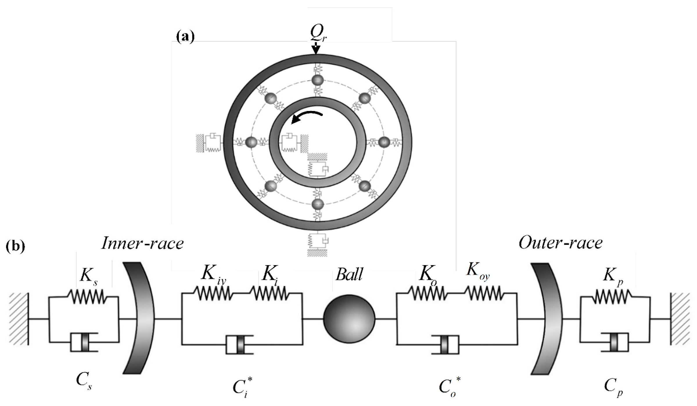
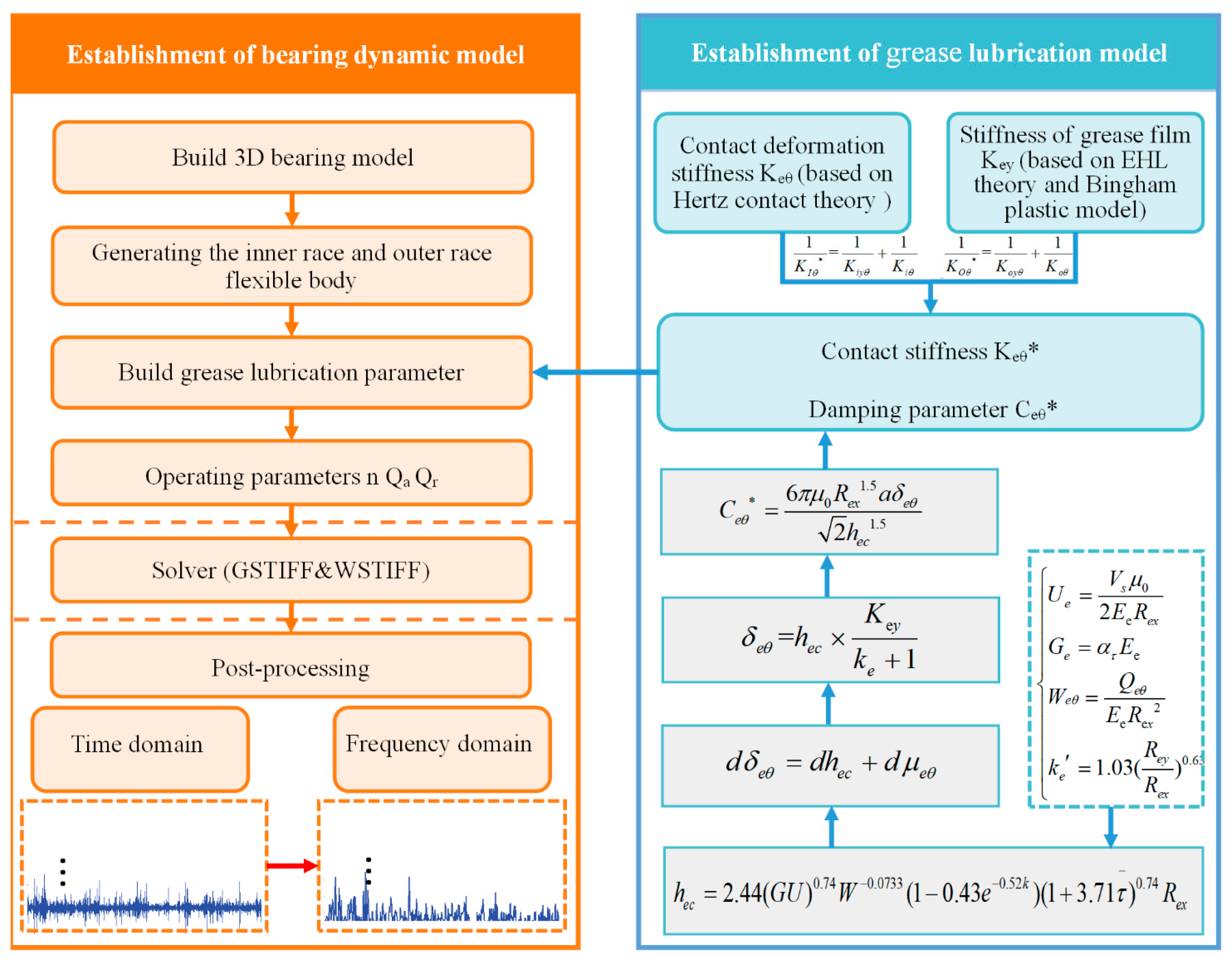
2. FRBD with Lubrication Model
2.1. Grease Lubrication Model
- Rolling bearings operate under isothermal conditions to avoid temperature interference with the model.
- The balls of the ball bearing model are equidistant from the surface of the inner race and the surface of the outer race, and there is no interaction between them.
- The contact form between the inner/outer race and the rolling elements of the bearing is Hertz contact. The contact between the cage and the rolling elements does not generate additional force.
- The center of mass of the rolling element is always maintained at the geometric center.
- There is no relative sliding between the inner race of the rolling bearing and the shaft. The angular velocity of the inner race remains the same as the rotational speed of the shaft.
- When the rolling element comes into contact with the seat ring, elastic deformation and local contact deformation will occur, but this will not change the overall shape and size of the bearing.
2.2. Flexible–Rigid Combined Fault Dynamic Model
3. Results
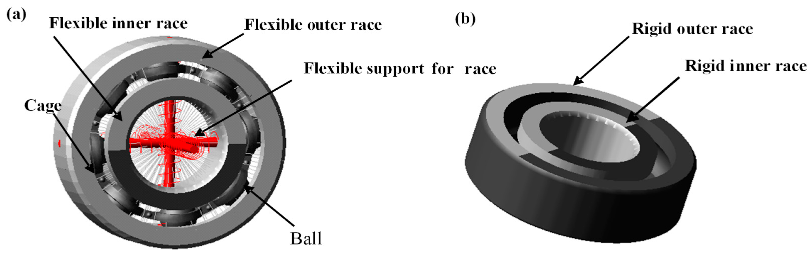
3.1. Rolling Bearing SKF 6203-RS Dynamic Model
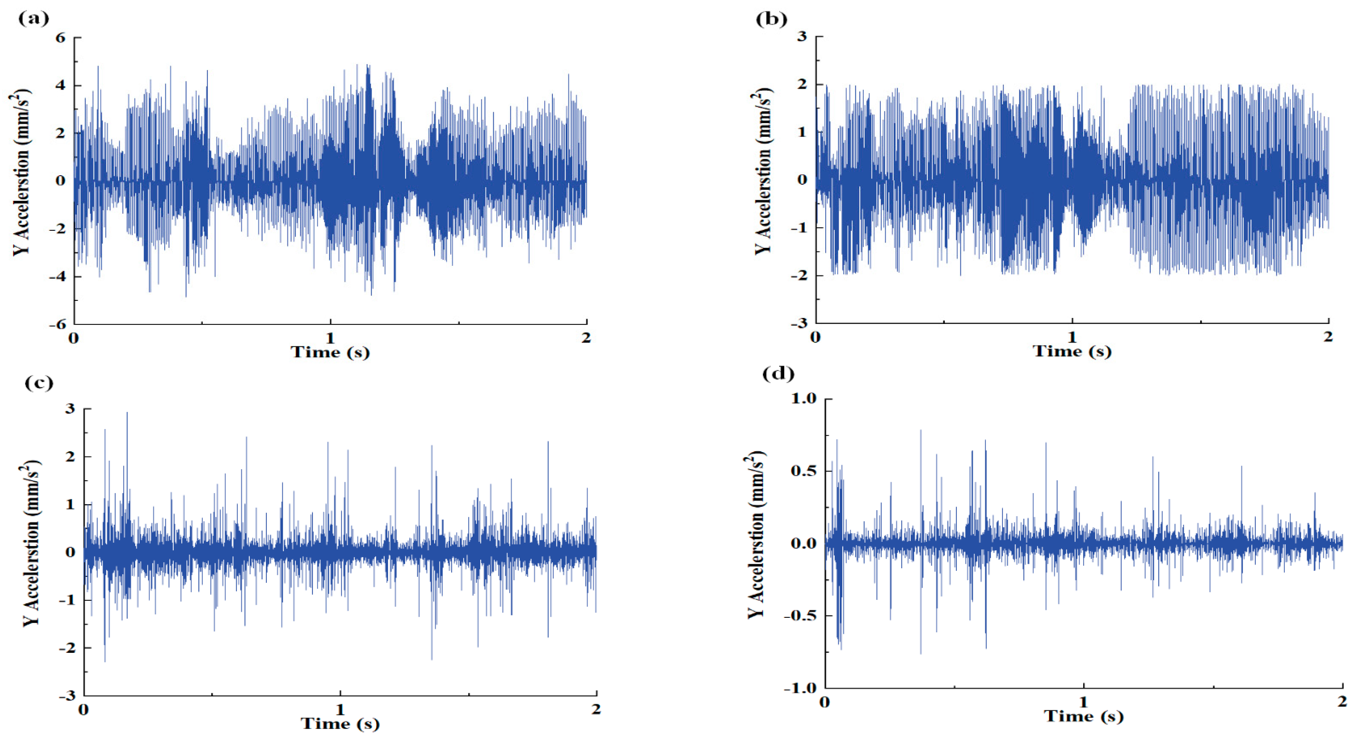
3.2. Analysis of the Influence of Flexible–Rigid Combined and Grease Lubrication on Rolling Bearing Vibration
3.3. FRBD with Lubrication Model Validation
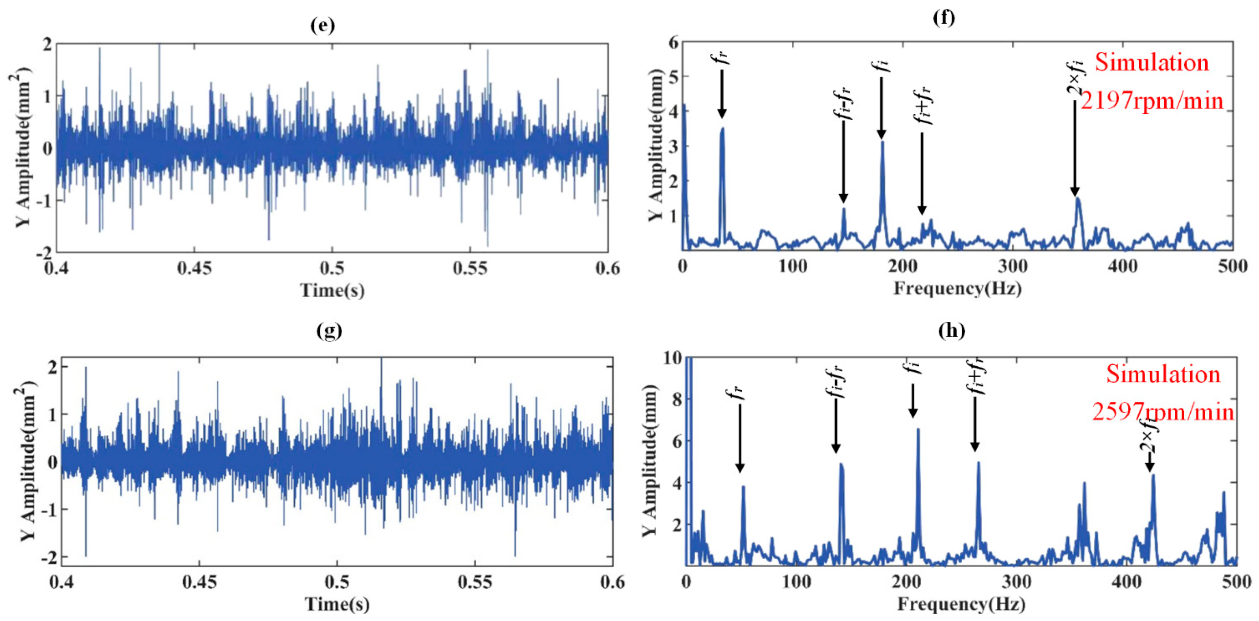
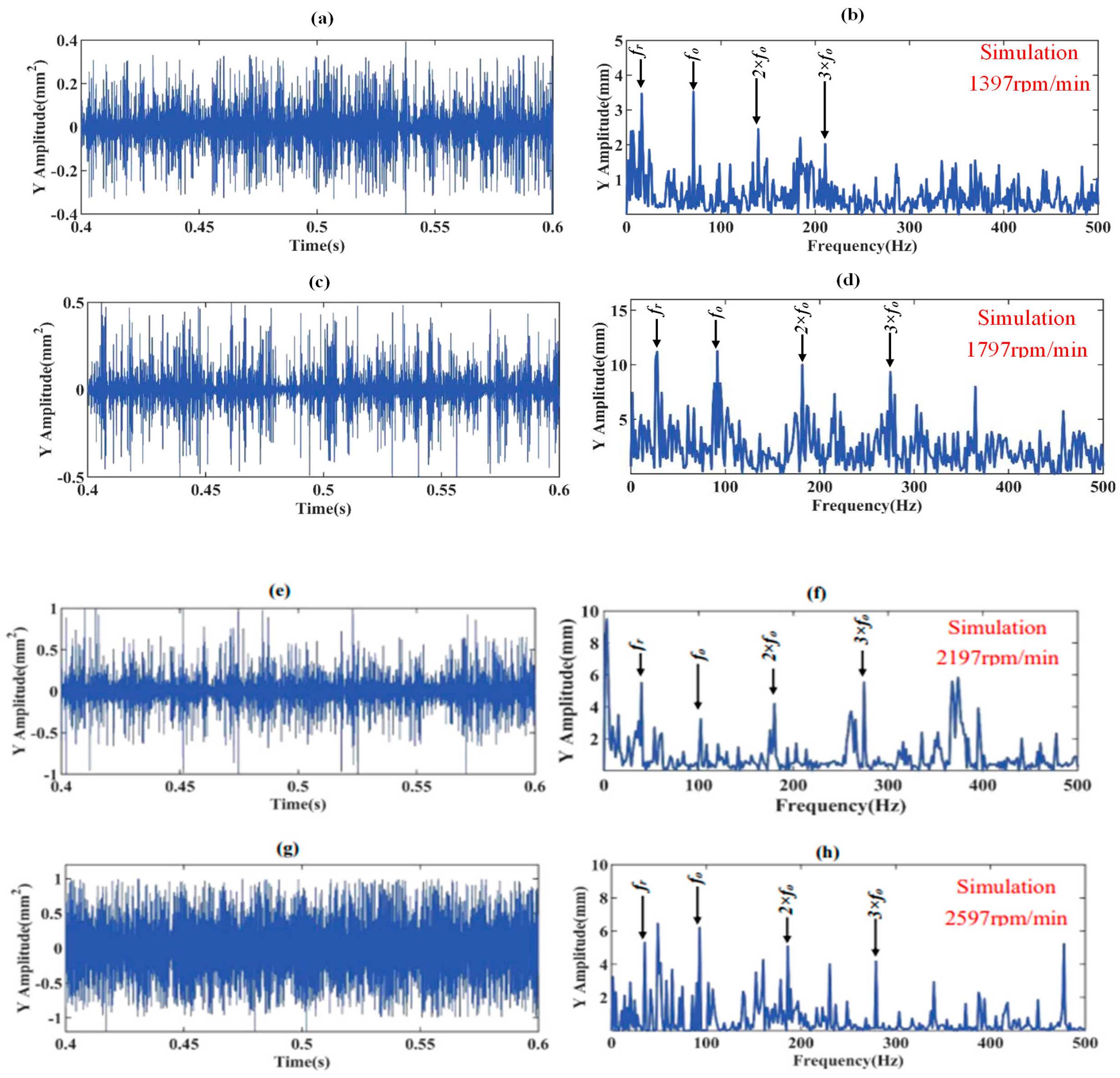
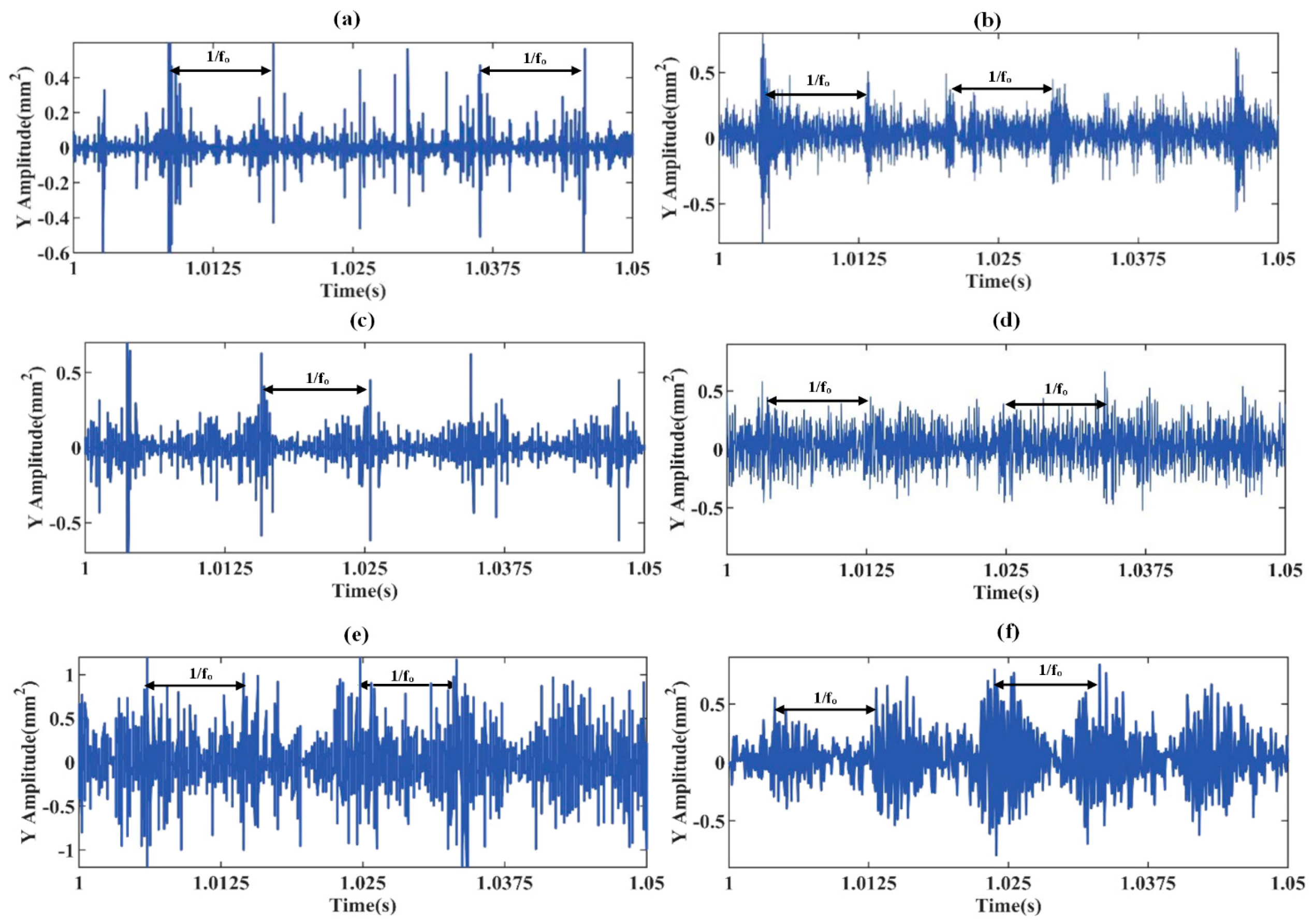
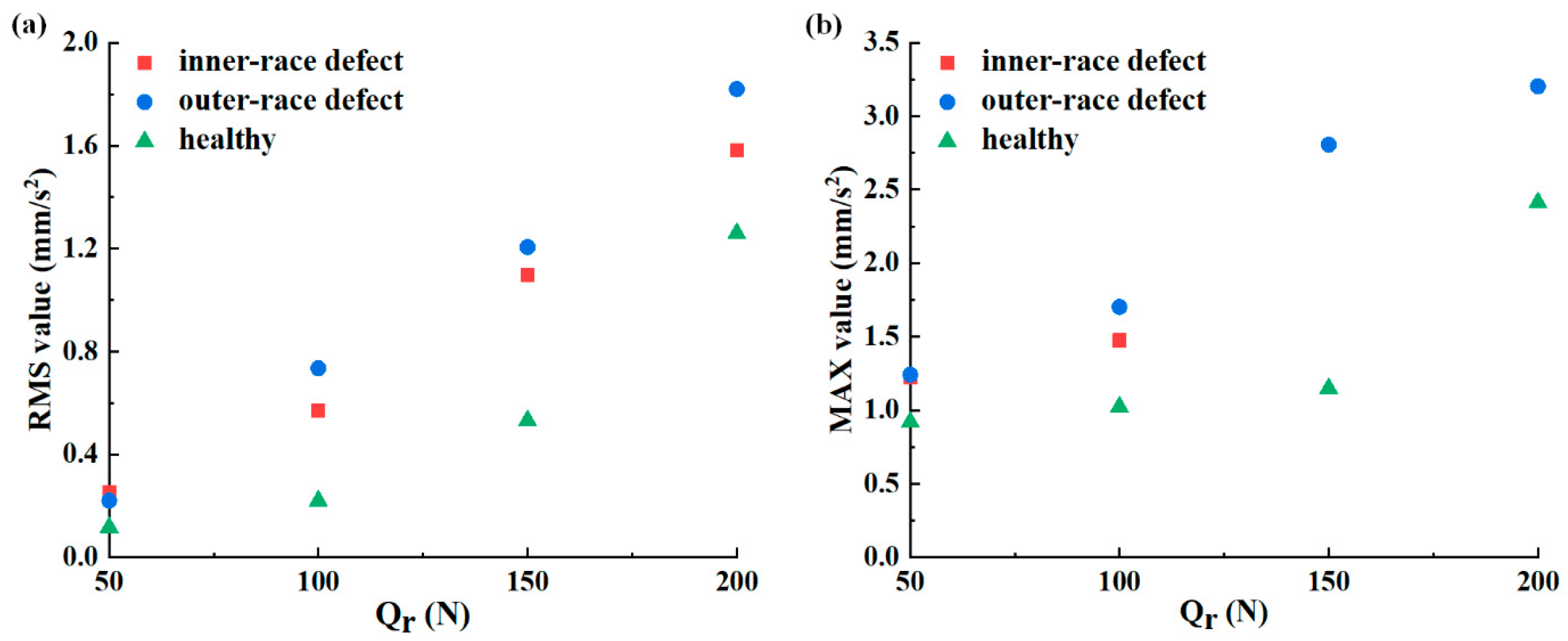
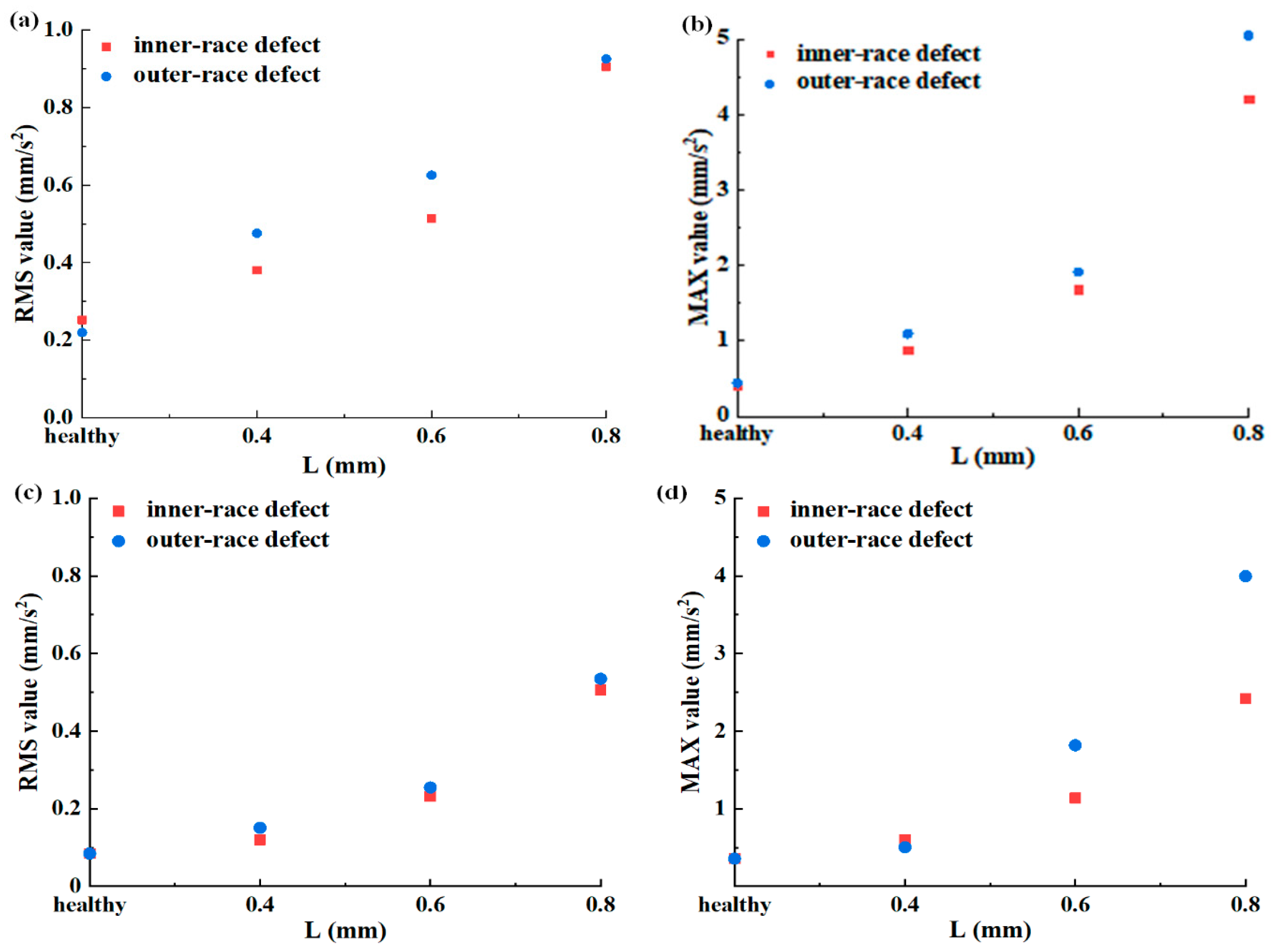
3.4. Effect of the Rotor Speed, Defect Position, Radial Load, and Defect Size on the Time- and Frequency-Domain Vertical Vibration Accelerations of FRBD with Lubrication Model
4. Conclusions
Author Contributions
Funding
Data Availability Statement
Conflicts of Interest
References
- Harris, T.A.; Kotzalas, M.N. Rolling Bearing Analysis; CRC Press: Boca Raton, FL, USA, 2006. [Google Scholar]
- Vencl, A.; Gašić, V.; Stojanović, B. Fault tree analysis of most common rolling bearing tribological failures. IOP Conf. Ser. Mater. Sci. Eng. 2017, 174, 12048. [Google Scholar] [CrossRef]
- Mochimaru, Y.; Liu, J. Analysis of oil-lubricated herringbone grooved journal bearing with trapezoidal cross-section, using a spectral finite difference method. J. Hydrodyn. 2010, 22 (Suppl. S1), 397–401. [Google Scholar]
- Bailey, N.Y.; Cliffe, K.A.; Hibberd, S.; Power, H. On the dynamics of a high-speed coned fluid-lubricated bearing. IMA J. Appl. Math. 2014, 79, 535–561. [Google Scholar] [CrossRef]
- Gao, X.; Yan, C.; Liu, Y.; Yan, P.; Yang, J.; Wu, L. A 4-DOF dynamic model for ball bearing with multiple defects on raceways. Proc. Inst. Mech. Eng. Part K J. Multi-Body Dyn. 2020, 235, 3–18. [Google Scholar] [CrossRef]
- Shah, D.S.; Patel, V.N. A dynamic model for vibration studies of dry and lubricated deep groove ball bearings considering local defects on races. Measurement 2019, 137, 535–555. [Google Scholar] [CrossRef]
- Liu, J.; Shao, Y. An improved analytical model for a lubricated rolling bearing including a localized defect with different edge shapes. J. Vib. Control 2018, 24, 3894–3907. [Google Scholar] [CrossRef]
- Cheng, H.; Zhang, Y.; Lu, W.; Yang, Z. Research on time-varying stiffness of bearing based on local defect and varying compliance coupling. Measurement 2019, 143, 155–179. [Google Scholar] [CrossRef]
- Kıral, Z.; Karagülle, H. Vibration analysis of rolling element bearings with various defects under the action of an unbalanced force. Mech. Syst. Signal Process. 2006, 20, 1967–1991. [Google Scholar] [CrossRef]
- Xie, K.; Liu, L.-C.; Li, X.-P.; Zhang, H.-L. Non-contact resistance and capacitance on-line measurement of lubrication oil film in rolling element bearing employing an electric field coupling method. Measurement 2016, 91, 606–612. [Google Scholar] [CrossRef]
- Zhu, W.; Ni, G.; Cao, Y.; Wang, H. Research on a rolling bearing health monitoring algorithm oriented to industrial big data. Measurement 2021, 185, 110044. [Google Scholar] [CrossRef]
- Zhao, D.S.; Wang, Y.Z.; Zhao, K. Fatigue life prediction of flexible bearings based on ABAQUS and Code-DesignLife. IOP Conf. Ser. Mater. Sci. Eng. 2019, 474, 7. [Google Scholar] [CrossRef]
- Solihat, M.K.; Behdinan, K. Nonlinear dynamic response and transmissibility of a flexible rotor system mounted on viscoelastic elements. Nonlinear Dyn. 2019, 97, 1581–1600. [Google Scholar] [CrossRef]
- Leontiev, M.; Ivannikov, V.; Degtyarev, S. Radial ball bearings with flexible rings application to rotor dynamics and extension to multi body simulations. In Proceedings of the International Symposium on Transport Phenomena and Dynamics of Rotating Machinery, Maui, HI, USA, 16–21 December 2017. [Google Scholar]
- Zhang, S.; Deng, S.; Zhang, W.; Kang, N. Simulation and experiment on sealing mechanism with rigid-flexible combined seal groove in hub bearing. Tribol. Int. 2019, 136, 385–394. [Google Scholar]
- Zhang, W.; Liu, Y.; Liao, Y.; Liu, P. The Dynamic Analysis of a Freight Train rolling bearing with Outer race Fault. In Proceedings of the First International Conference on Rail Transportation 2017, Chengdu, China, 10–12 July 2018. [Google Scholar]
- Sun, X.; Zhang, W.; Tian, H. Theoretical analysis of cylindrical rolling bearing with flexible races mounted in groove elastic support. J. Adv. Mech. Des. Syst. Manuf. 2020, 14, AMDSM0102. [Google Scholar] [CrossRef]
- Xu, K.; Kong, X.; Wang, Q.; Yang, S.; Huang, N.; Wang, J. A bearing fault diagnosis method without fault data in new working condition combined dynamic model with deep learning. Adv. Eng. Inform. 2022, 54, 101795. [Google Scholar] [CrossRef]
- Wu, Z.; Jiang, H.; Zhu, H.; Wang, X. A knowledge dynamic matching unit-guided multi-source domain adaptation network with attention mechanism for rolling bearing fault diagnosis. Mech. Syst. Signal Process. 2023, 189, 110098. [Google Scholar] [CrossRef]
- Meng, F.; Chen, Y. Analysis of elasto-hydrodynamic lubrication of journal bearing based on different numerical methods. Ind. Lubr. Tribol. 2015, 67, 486–497. [Google Scholar] [CrossRef]
- Yu, J.; Yuan, W.; Li, S.; Yao, W. Assessment of Bearing Dynamic Characteristics by Numerical Modeling with Effects of Oil Film and Centrifugal Deformation. Math. Probl. Eng. 2018, 1, 1619297. [Google Scholar] [CrossRef]
- Bastami, A.R.; Vahid, S. A comprehensive evaluation of the effect of defect size in rolling element bearings on the statistical features of the vibration signal. Mech. Syst. Signal Process. 2021, 151, 107334. [Google Scholar] [CrossRef]
- Tsuha, N.A.; Cavalca, K.L. Stiffness and damping of EHL line contact applied to cylindrical rolling bearing dynamic model. J. Sound Vib. 2020, 481, 115444. [Google Scholar] [CrossRef]
- Li, Y.; Cui, Y.; Deng, S. Dynamic characteristics of rigid-elastic-liquid-coupled ball bearings considering elastohydrodynamic lubrication. Mech. Mach. Theory 2024, 201, 105727. [Google Scholar] [CrossRef]
- Su, S.; Cao, H.; Zhang, Y. Dynamic modeling and characteristics analysis of cylindrical roller bearing with the surface texture on raceways. Mech. Syst. Signal Process. 2021, 158, 107709. [Google Scholar] [CrossRef]
- Piet, M. Grease Lubrication in Rolling Bearings; John Wiley & Sons: Hoboken, NJ, USA, 2012. [Google Scholar]
- Dowson, D.; Higginson, G.R. Elastohydrodynamic Lubrication; Pergamon Press: Oxford, UK, 1977. [Google Scholar]
- Harmlock, B.J.; Dowson, D. Isothermal Elastohydro Dynamic Lubricantion of Point Contacts, part III—Fully Flooded Results. J. Lubr. Tech. 1977, 99, 264–275. [Google Scholar]
- Harris, T.A.; Kotzalas, M.N. Essential Concepts of Bearing Technology, Rolling Bearing Analysis, 5th ed.; Taylor & Francis: Boca Raton, FL, USA, 2006; pp. 184–192. [Google Scholar]
- Palmgren, A. Ball and Ball Bearing Engineering, 3rd ed.; Burbank: Philadelphia, PA, USA, 1946. [Google Scholar]
- Yang, Z.; Qian, X. A study of grease film thicknesses in elastorheodynamic rolling point contacts. Lubr. Sci. 1990, 2, 273–284. [Google Scholar]
- Liu, J.; Pang, R.; Ding, S.; Li, X. Vibration analysis of a planetary gear with the flexible ring and planet bearing fault. Measurement 2020, 165, 108100. [Google Scholar] [CrossRef]
- Case Western Reserve University Bearing Data Center Website. Available online: https://engineering.case.edu/bearingdatacenter/apparatus-and-procedures (accessed on 4 January 2024).
- Dong, Y.; Li, Y.; Zheng, H.; Wang, R.; Xu, M. A new dynamic model and transfer learning based intelligent fault diagnosis framework for rolling element bearings race faults: Solving the small sample problem. ISA Trans. 2022, 121, 327–348. [Google Scholar] [CrossRef]


| Defect Cases | Depth H (mm) | Length L (mm) | Circle Radius r (mm) | Inner-Race Speed | Defect Cases | Depth H (mm) | |
|---|---|---|---|---|---|---|---|
| Inner-race defect | 1 | 0.3 | 0.4 | 0.15 | 1397 | 50 | 6 |
| 2 | 0.3 | 0.4 | 0.15 | 1797 | 50 | 6 | |
| 3 | 0.3 | 0.4 | 0.15 | 2197 | 50 | 6 | |
| 4 | 0.3 | 0.4 | 0.15 | 2597 | 50 | 6 | |
| 5 | 0.3 | 0.4 | 0.15 | 1797 | 100 | 6 | |
| 6 | 0.3 | 0.4 | 0.15 | 1797 | 150 | 6 | |
| 7 | 0.3 | 0.4 | 0.15 | 1797 | 200 | 6 | |
| 8 | 0.4 | 0.6 | 0.2 | 1797 | 50 | 13 | |
| 9 | 0.5 | 0.8 | 0.25 | 1797 | 50 | 18 | |
| Outer-race defect | 10 | 0.3 | 0.4 | 0.15 | 1397 | 50 | 6 |
| 11 | 0.3 | 0.4 | 0.15 | 1797 | 50 | 6 | |
| 12 | 0.3 | 0.4 | 0.15 | 2197 | 50 | 6 | |
| 13 | 0.3 | 0.4 | 0.15 | 2597 | 50 | 6 | |
| 14 | 0.3 | 0.4 | 0.15 | 1797 | 100 | 6 | |
| 15 | 0.3 | 0.4 | 0.15 | 1797 | 150 | 6 | |
| 16 | 0.3 | 0.4 | 0.15 | 1797 | 200 | 6 | |
| 17 | 0.4 | 0.6 | 0.2 | 1797 | 50 | 13 | |
| 18 | 0.5 | 0.8 | 0.25 | 1797 | 50 | 18 | |
| Parameters | Value |
|---|---|
| Number of balls (Z) | 8 |
| Pitch diameter (dm) | 28.500 mm |
| Ball diameter (db) | 6.746 mm |
| Inner race diameter (di) | 17 mm |
| Outer race diameter (do) | 40 mm |
| Width (B) | 12 mm |
| ) | ) | ) |
|---|---|---|
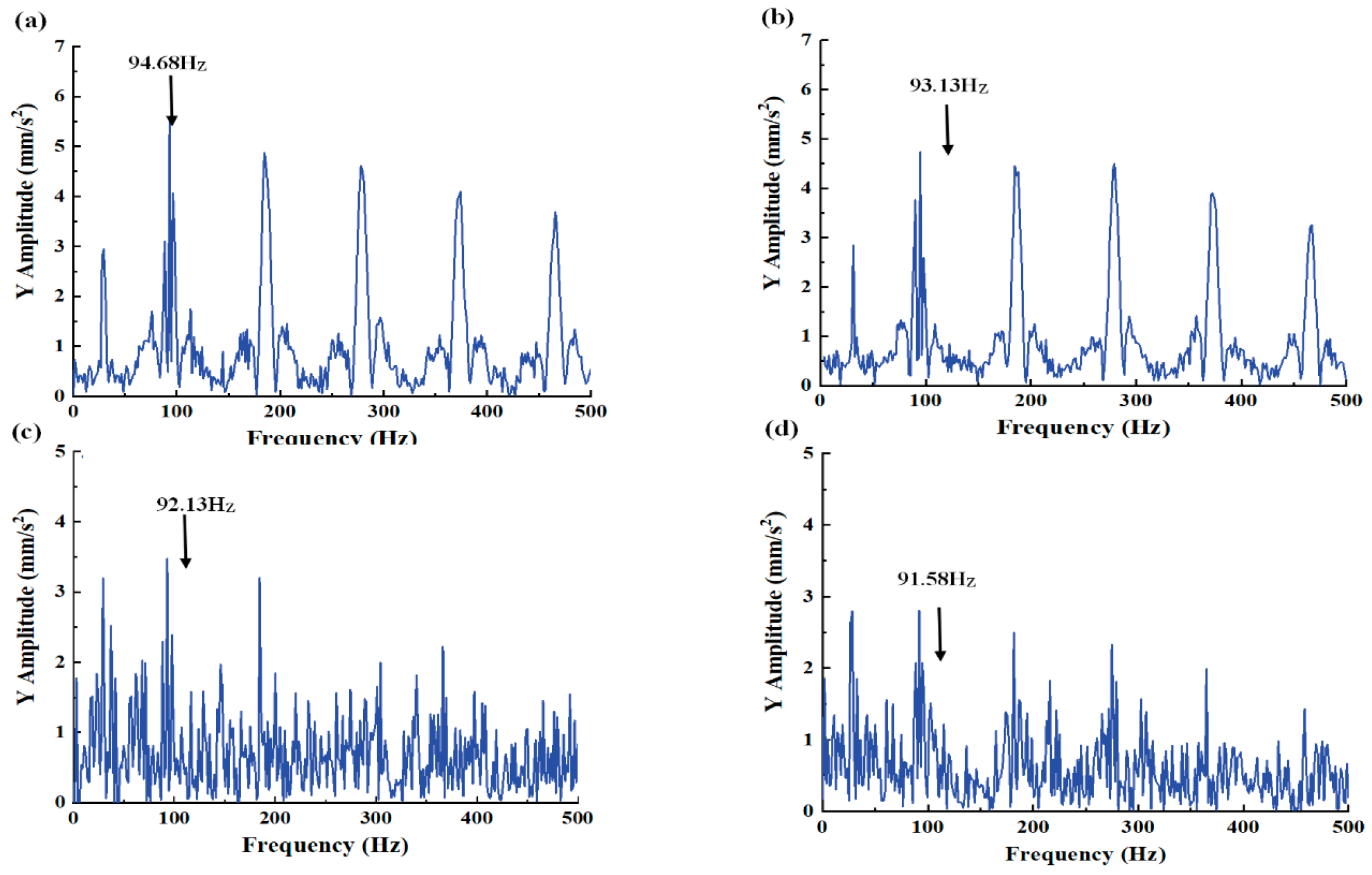
| 29.950 Hz | 91.445 Hz | 11.430 Hz |
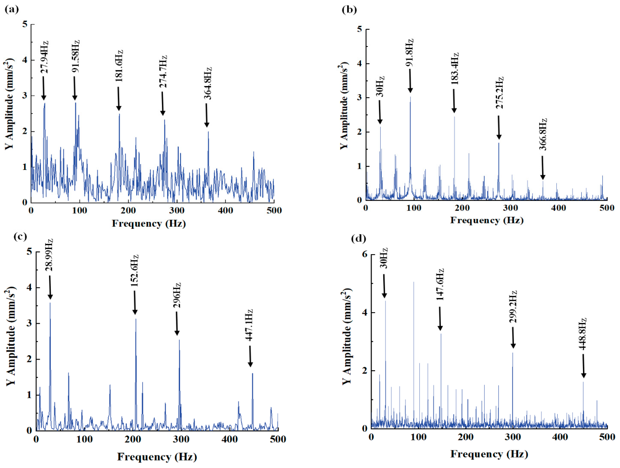
| Numerical Comparison Between Simulation Results and Experimental Results of Outer-Race Defect Bearing | |||
|---|---|---|---|
| Frequency | Simulation (HZ) | Experiment (HZ) | Error |
| 27.94 | 30 | 6.87% | |
| 91.58 | 91.8 | 0.24% | |
| 181.6 | 183.4 | 0.99% | |
| 274.7 | 275.2 | 0.18% | |
| 364.8 | 366.8 | 0.32% | |
| Numerical Comparison Between Simulation Results and Experimental Results of Inner-Race Defect Bearing | |||
| Frequency | Simulation (HZ) | Experiment (HZ) | Error |
| 28.99 | 30 | 3.48% | |
| 152.6 | 147.6 | 3.28% | |
| 296 | 299.2 | 1.08% | |
| 447.1 | 448.8 | 0.38% | |
Disclaimer/Publisher’s Note: The statements, opinions and data contained in all publications are solely those of the individual author(s) and contributor(s) and not of MDPI and/or the editor(s). MDPI and/or the editor(s) disclaim responsibility for any injury to people or property resulting from any ideas, methods, instructions or products referred to in the content. |
© 2025 by the authors. Licensee MDPI, Basel, Switzerland. This article is an open access article distributed under the terms and conditions of the Creative Commons Attribution (CC BY) license (https://creativecommons.org/licenses/by/4.0/).
Share and Cite
Wang, Q.; Liu, Z.; Ma, X.; Wang, Z.; Yu, J. An Improved Analytical Model of a Flexible–Rigid Combined Rolling Bearing with Elastohydrodynamic Lubrication. Machines 2025, 13, 499. https://doi.org/10.3390/machines13060499
Wang Q, Liu Z, Ma X, Wang Z, Yu J. An Improved Analytical Model of a Flexible–Rigid Combined Rolling Bearing with Elastohydrodynamic Lubrication. Machines. 2025; 13(6):499. https://doi.org/10.3390/machines13060499
Chicago/Turabian StyleWang, Qinchao, Zhilong Liu, Xinguang Ma, Zhengquan Wang, and Junqin Yu. 2025. "An Improved Analytical Model of a Flexible–Rigid Combined Rolling Bearing with Elastohydrodynamic Lubrication" Machines 13, no. 6: 499. https://doi.org/10.3390/machines13060499
APA StyleWang, Q., Liu, Z., Ma, X., Wang, Z., & Yu, J. (2025). An Improved Analytical Model of a Flexible–Rigid Combined Rolling Bearing with Elastohydrodynamic Lubrication. Machines, 13(6), 499. https://doi.org/10.3390/machines13060499