
Design and Optimization of a Novel Compliant Z-Positioner for the Nanoindentation Testing Device


Abstract
1. Introduction
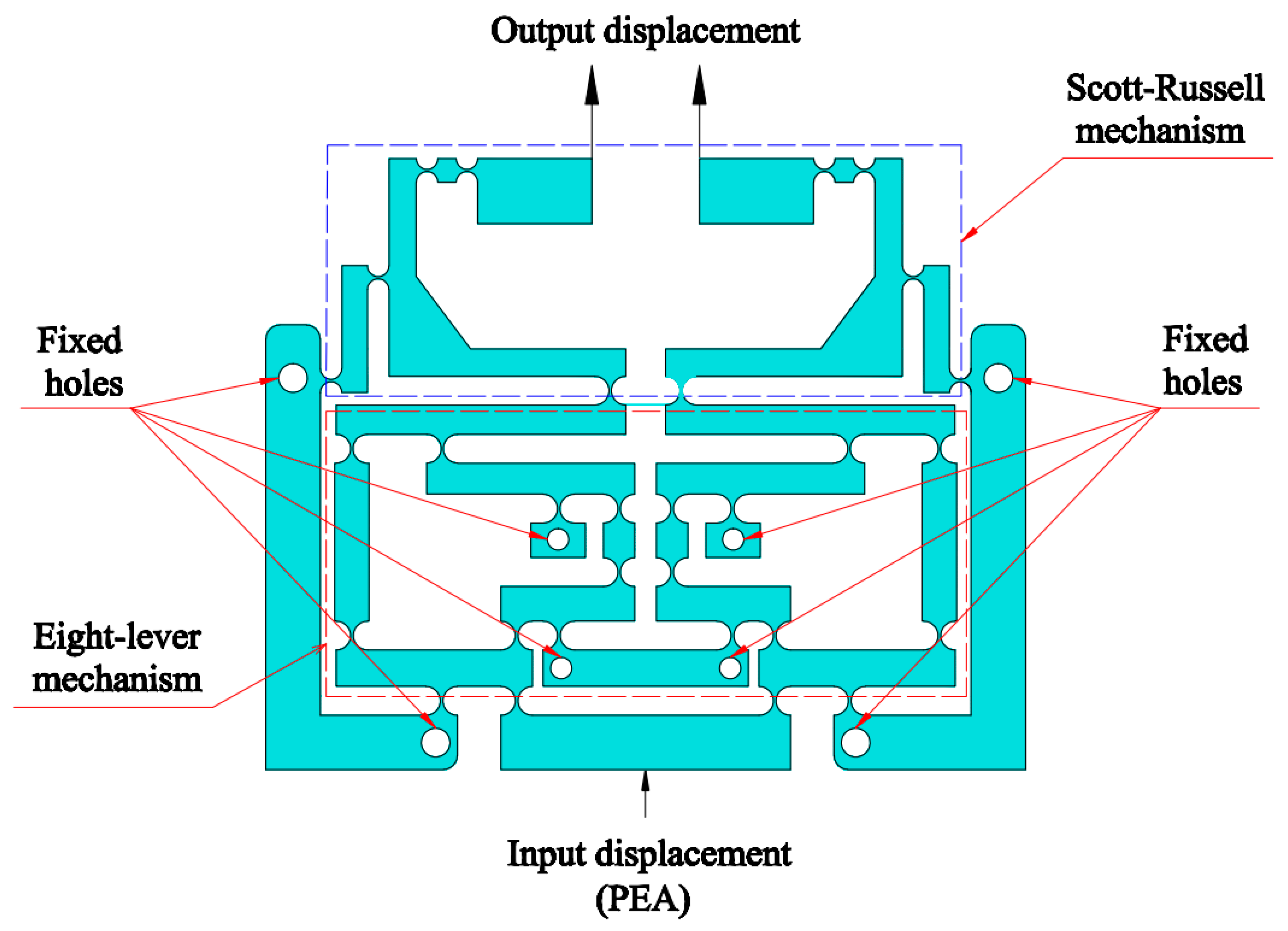
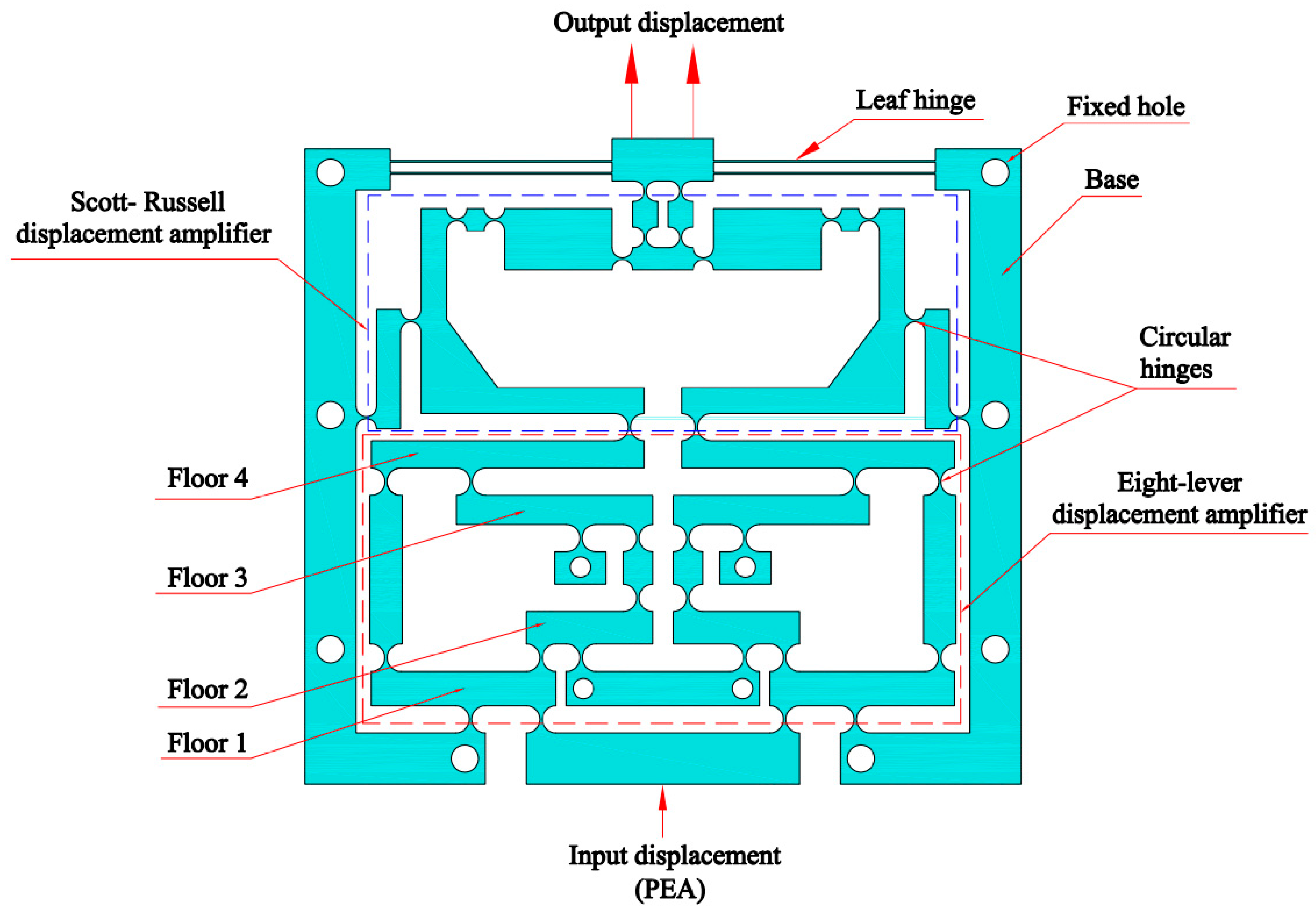
- − A new hybrid compliant displacement amplifier, comprising symmetric four-lever and symmetric Scott Russell structures, was integrated into the Z-positioner to enhance the output working stroke for directing the indenter in a nanoindentation testing device;
- − A parallel-symmetric leading structure was applied to reduce the small decoupling mobility error according to the symmetrical mechanism to enhance the positioning control;
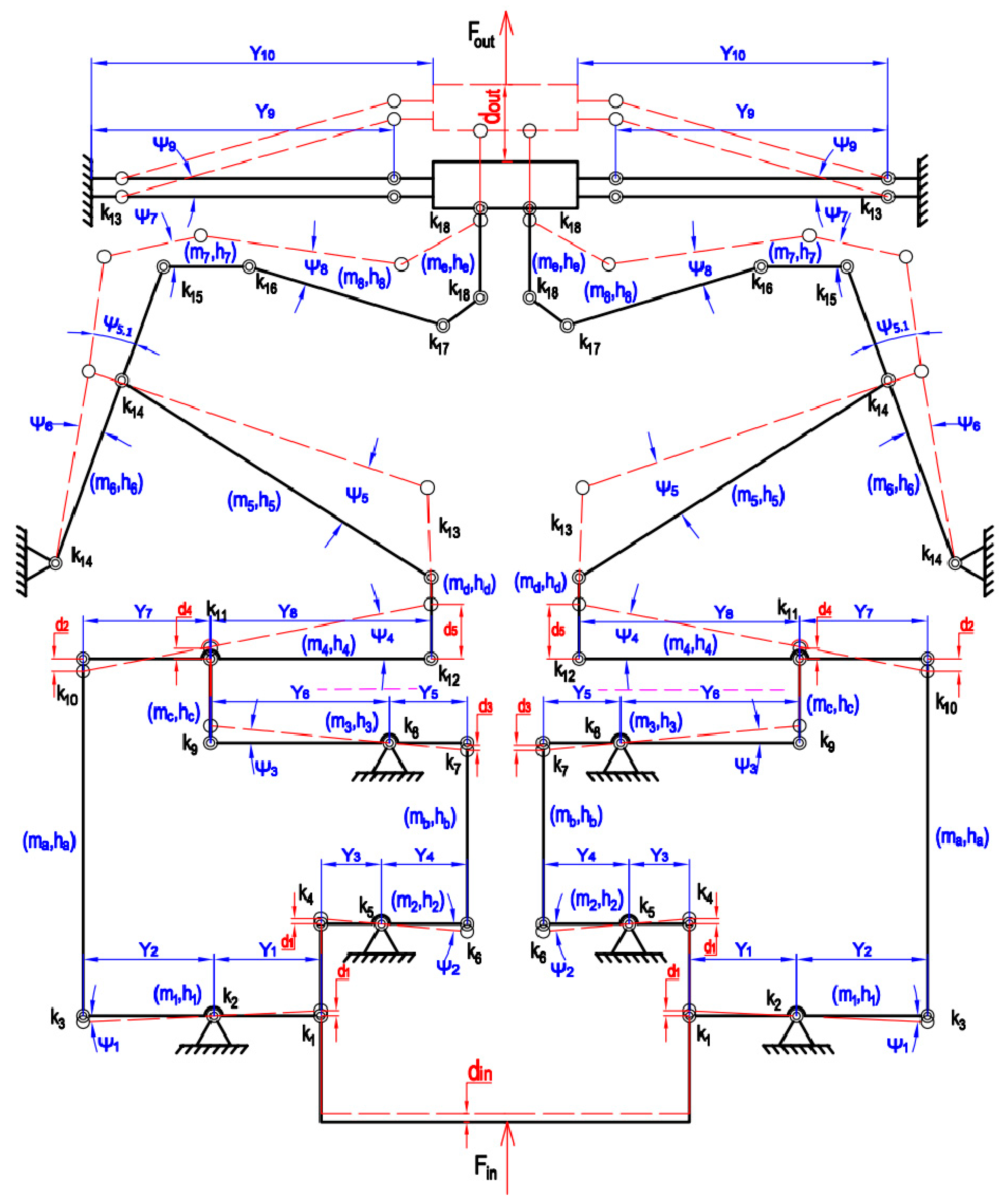
- − A hybrid approach of the PRBM, the Lagrange technique, the Firefly algorithm and FEA analysis was applied for analytical modeling, optimization and result verification.
2. Mechanical Structure of a New Flexure-Based 1-DOF Positioner
3. Analytical Model for Proposed Positioner
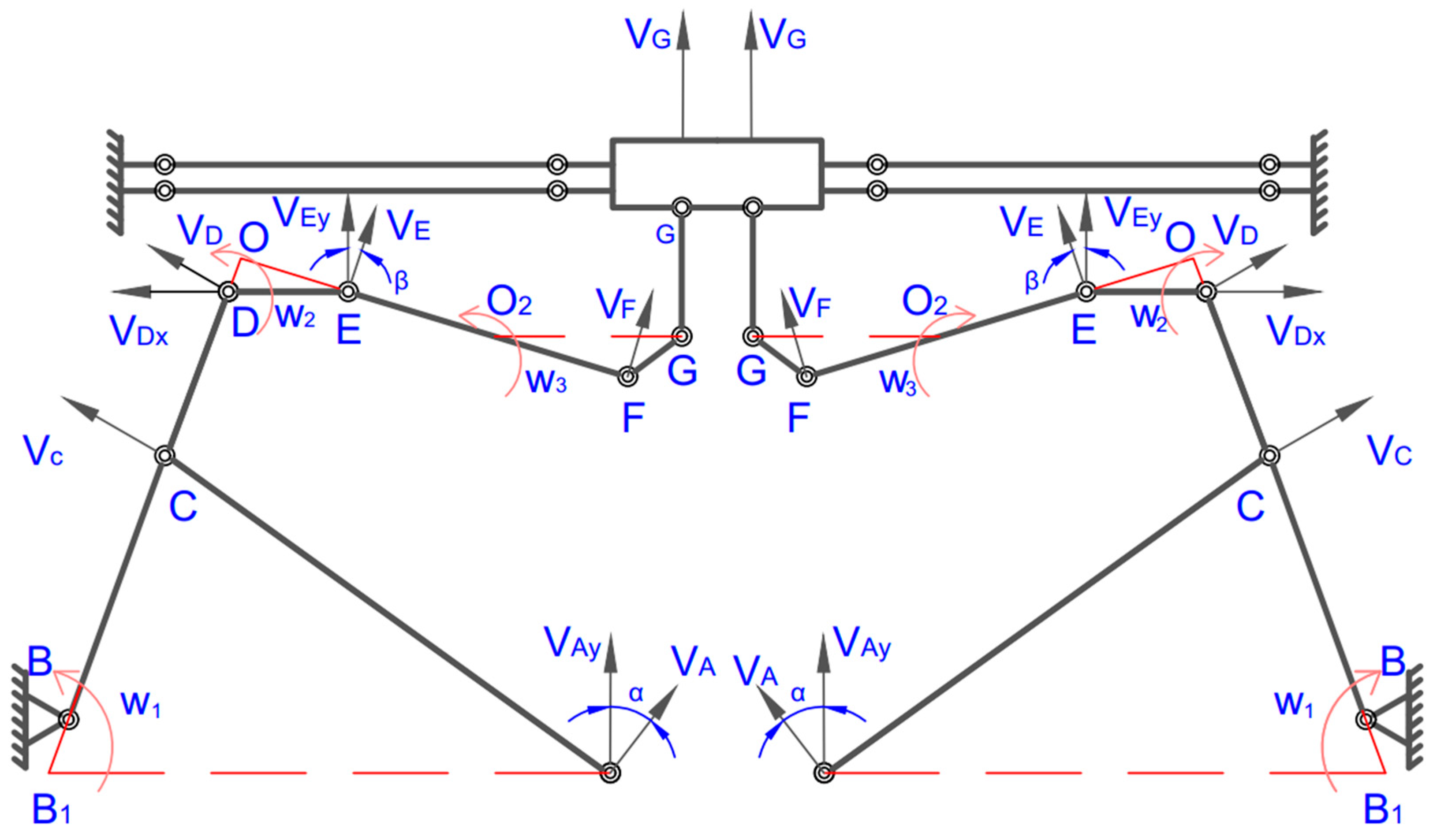
3.1. Static–Dynamic Analysis
3.2. Analytic Model Validation
3.3. Decoupling Mobility Error Analysis for Developed Positioner
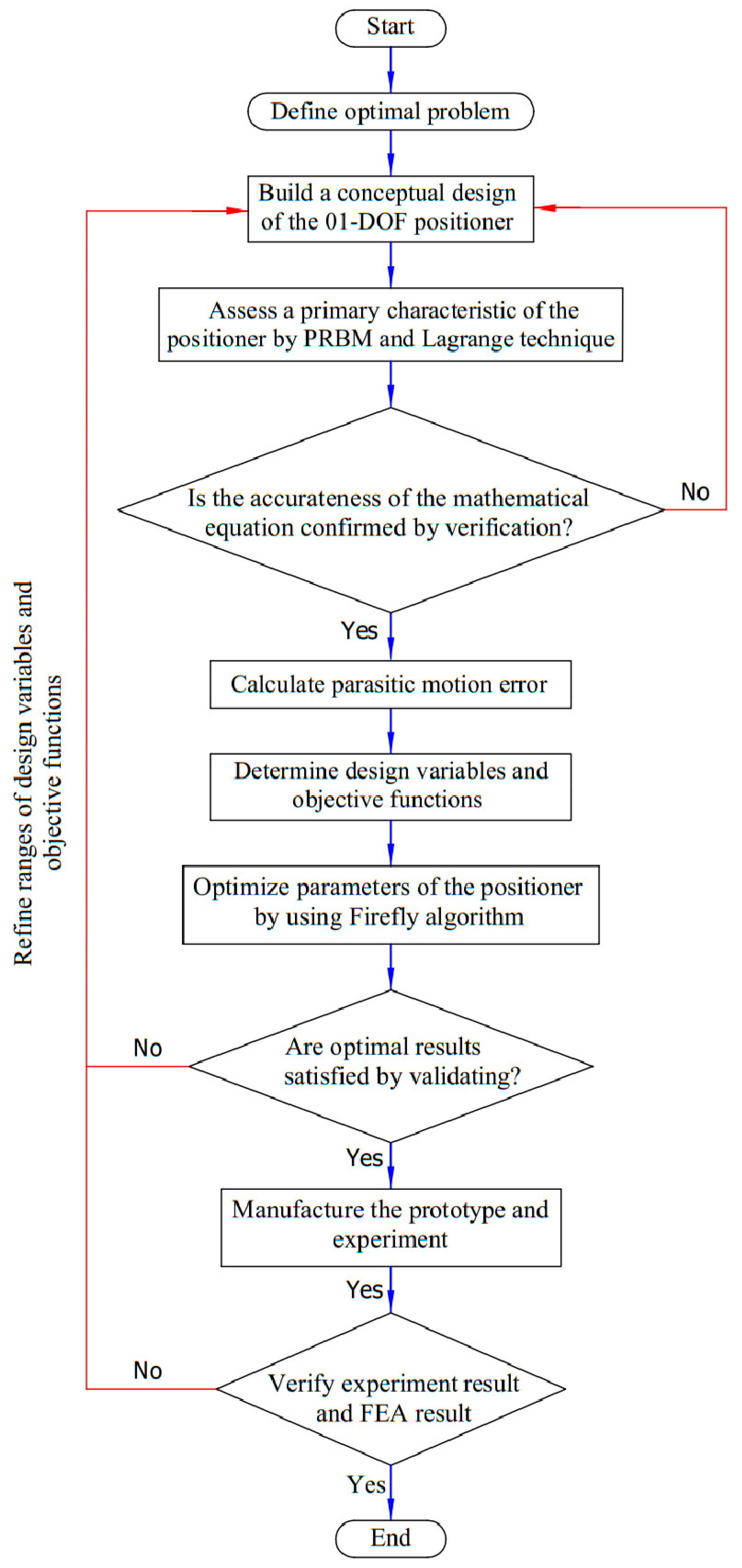
4. Suggested Hybrid Approach
- − Develop a novel structure for potential application in guiding mechanisms for nanoindentation testing systems, utilizing a new hybrid displacement magnifier and a symmetric-parallel leading structure.
- − Establish static and dynamic characteristics by the PRBM and Lagrange technique.
- − Validate analytical results by FEA analysis.
- − Define the main input parameters, output response, as well as limits and constraints for design variables and objective function.
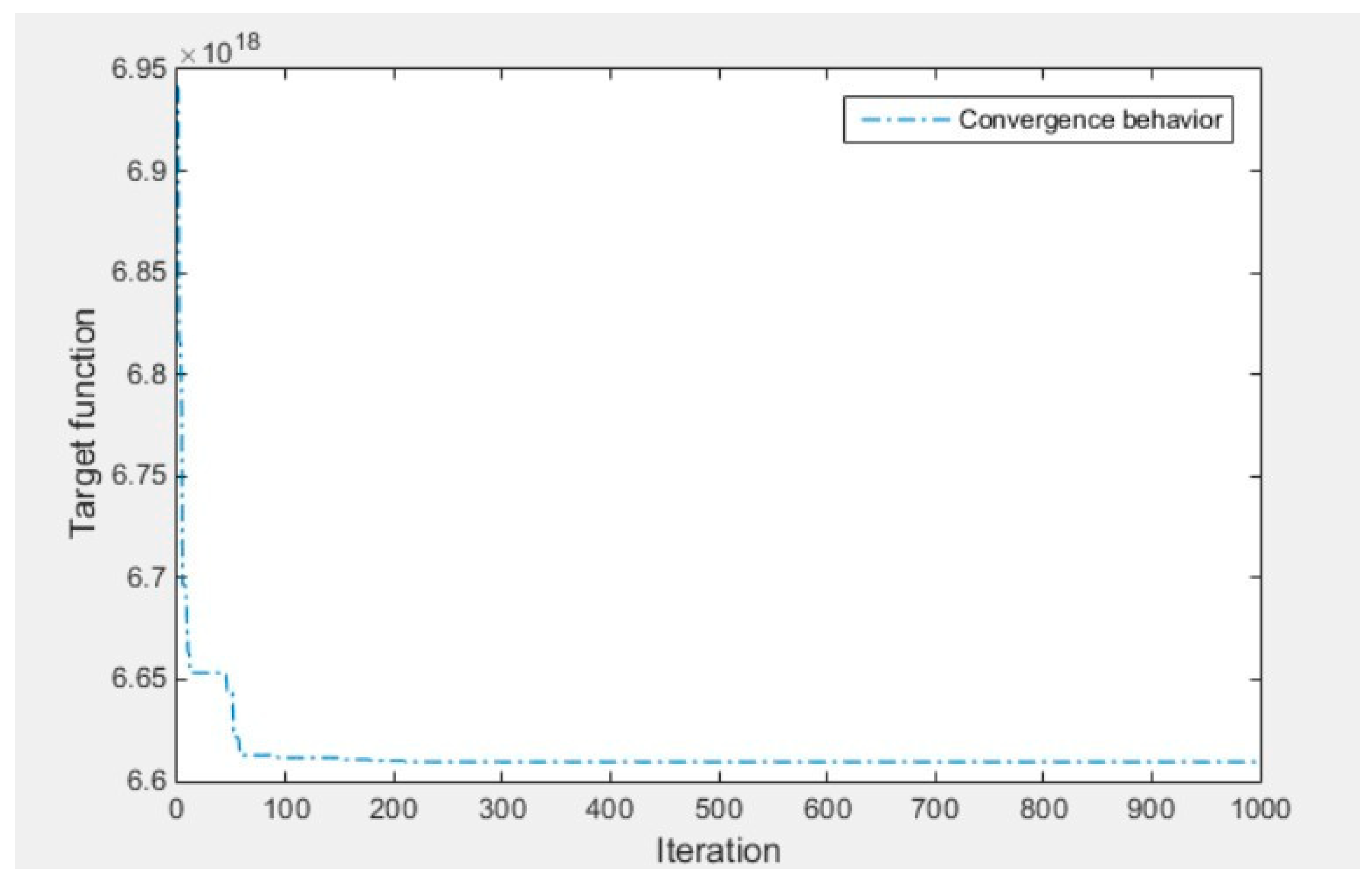
- − Optimize main design variables to enhance the quality response using the algorithm.
- − Verify optimized results by FEA analysis.
- − Fabricate the prototype based on optimal results.
- − Conduct experiments to check the quality response and validate FEA results.
- − Compare the quality response of the proposed positioner with the prior research.
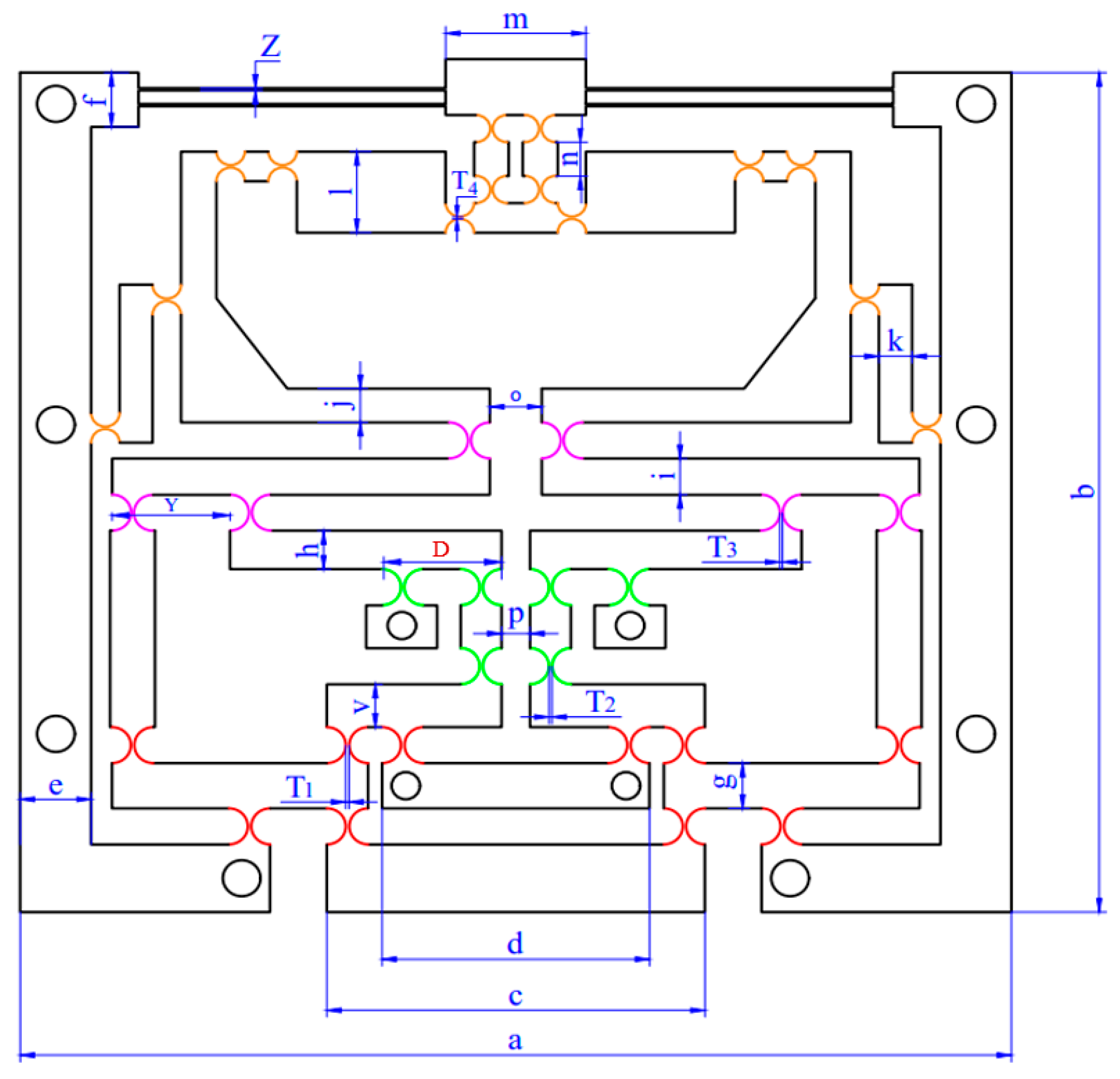
4.1. Parameter Optimization of a Fine Z-Positioner
1 ≤ T2 ≤ 1.1
0.9 ≤ T3 ≤ 1
0.8 ≤ T4 ≤ 0.9
23 ≤ D ≤ 27
22 ≤ Y ≤ 26
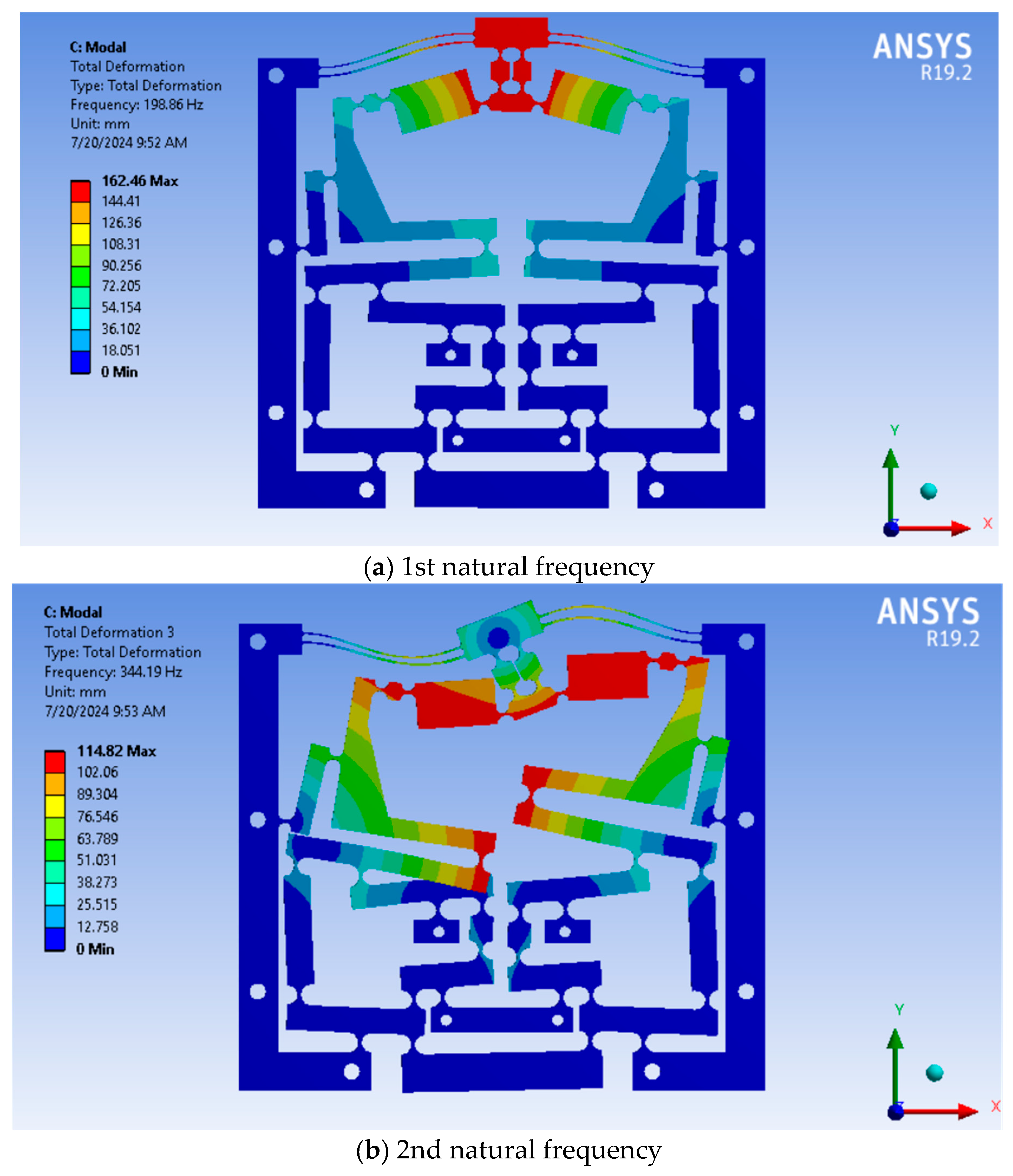
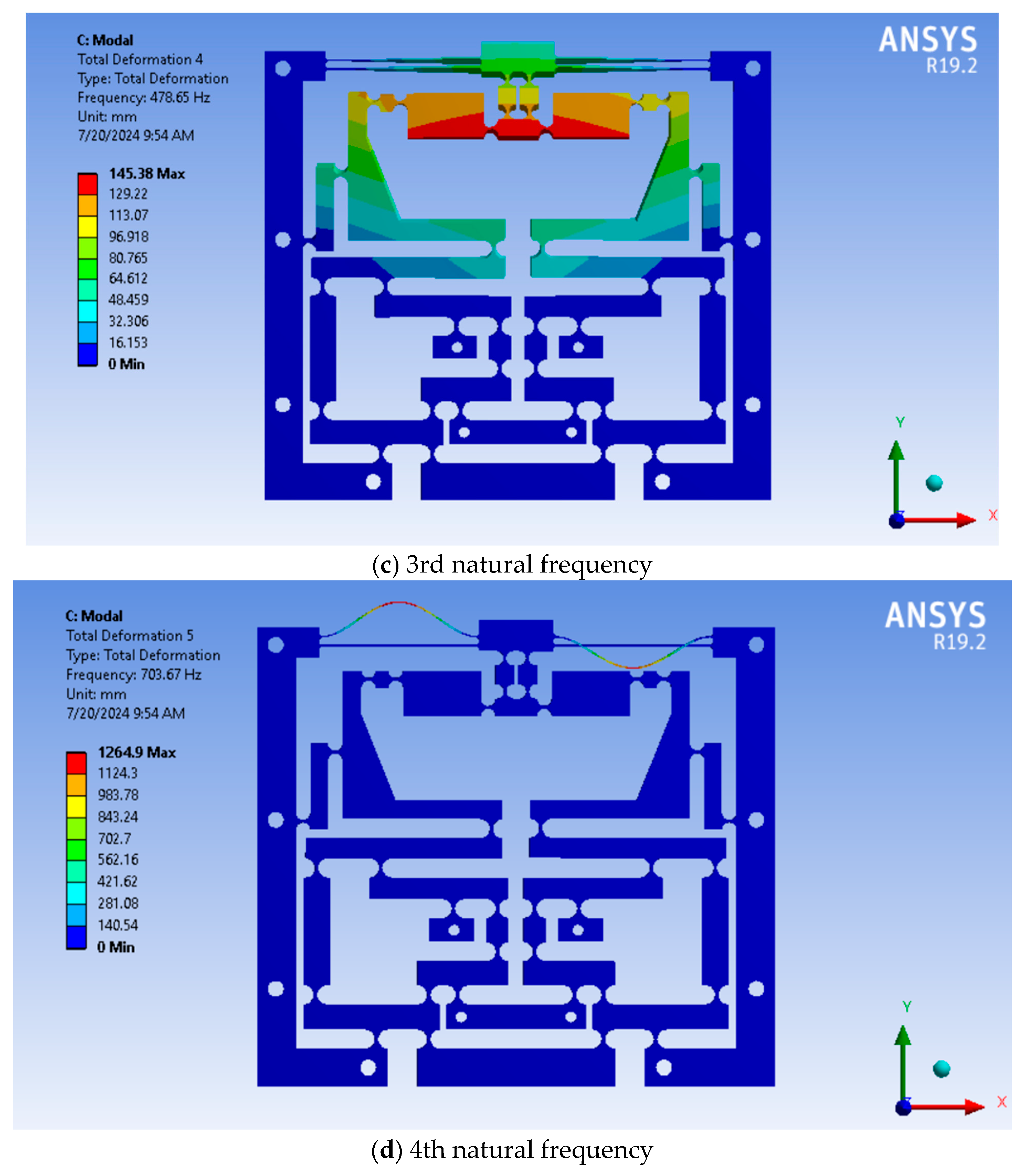
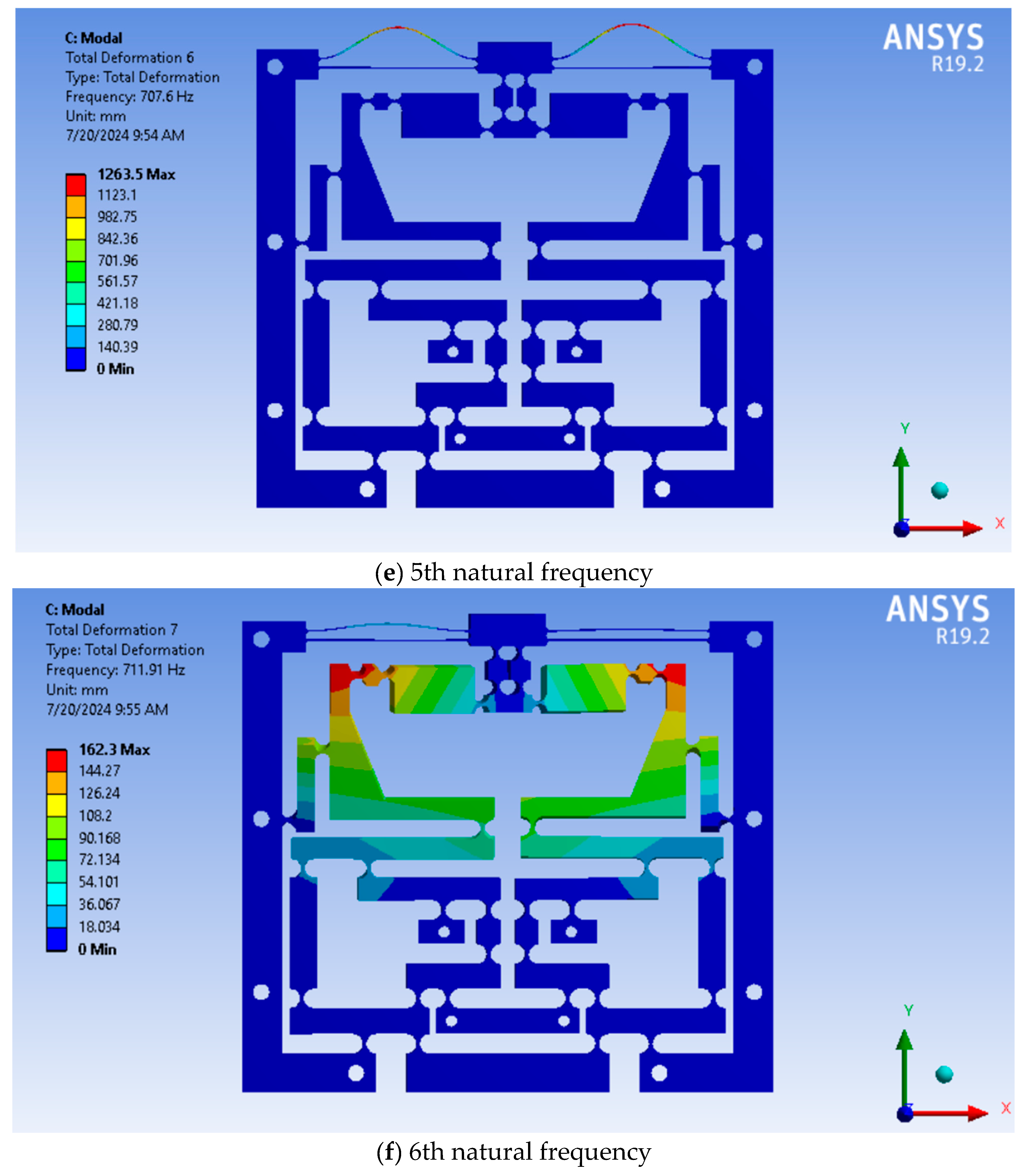
4.2. FEA Verification
4.3. Experiment Investigation
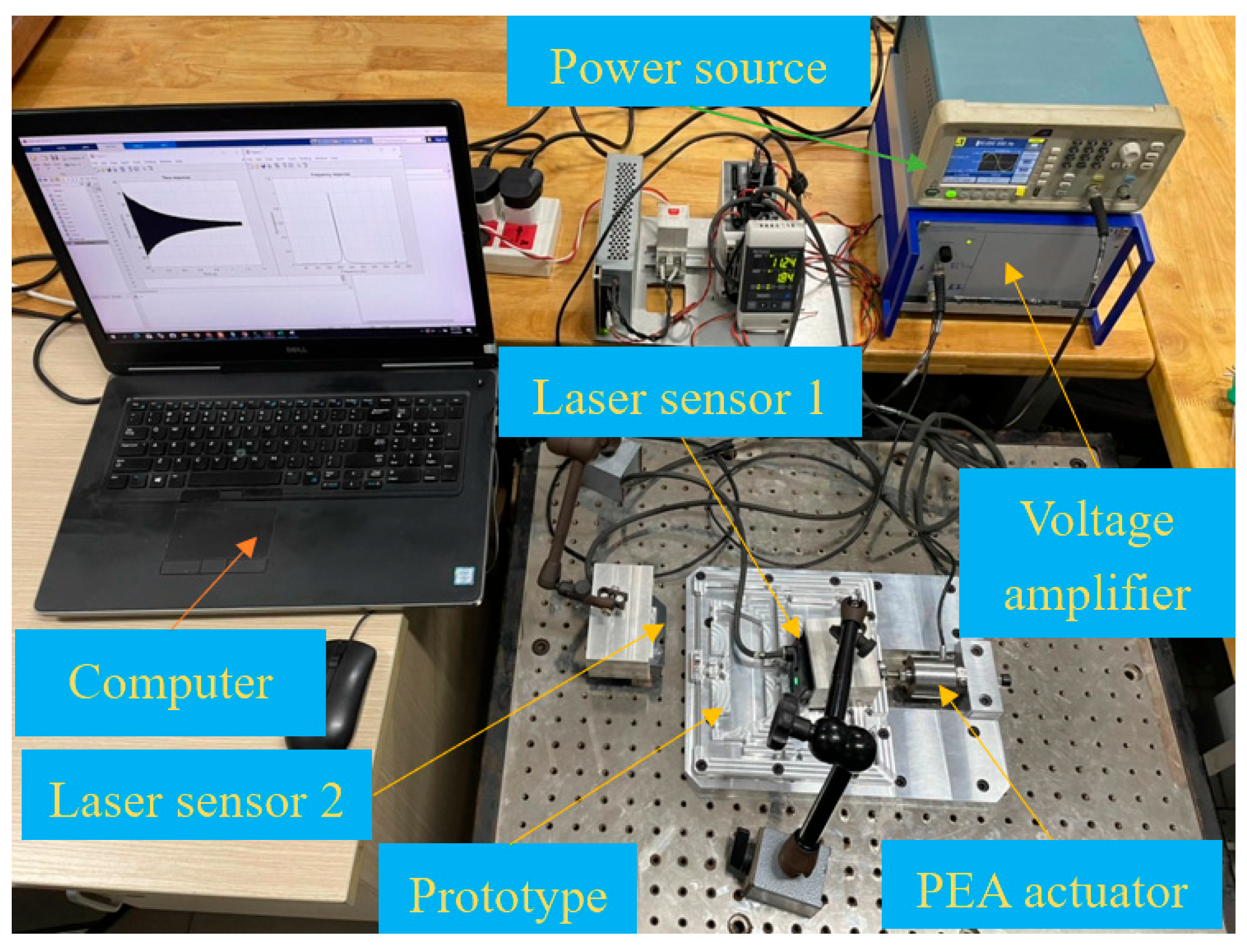
4.3.1. Prototype Production and Experiment Layout
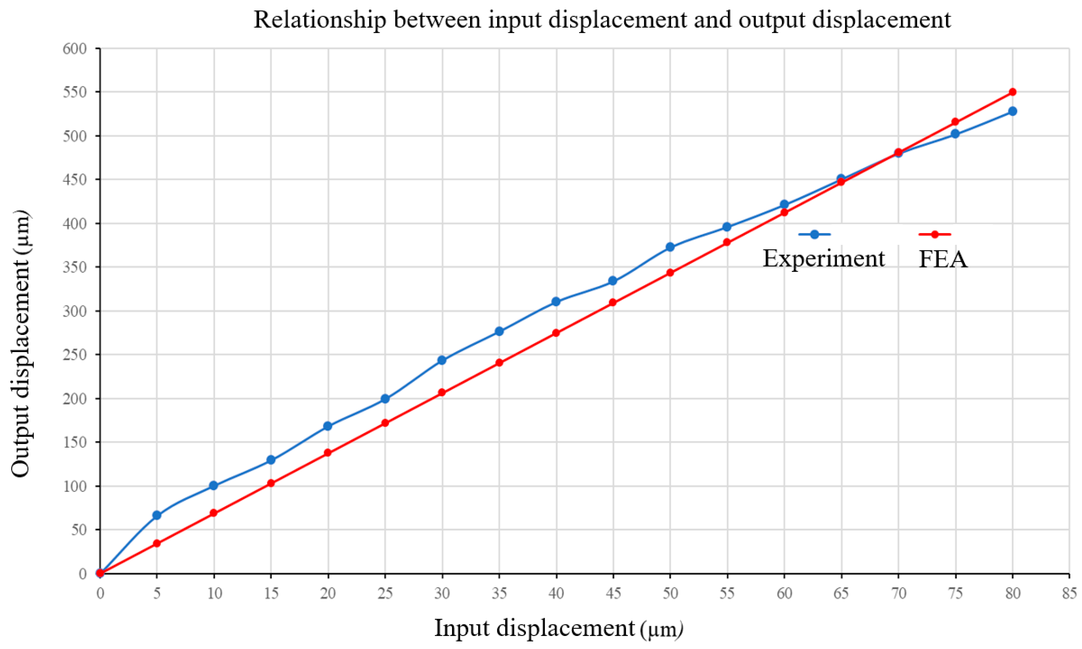
4.3.2. Experiment Outcomes
5. Conclusions
Author Contributions
Funding
Data Availability Statement
Acknowledgments
Conflicts of Interest
References
- Xu, Q. Design and testing of a novel multi-stroke micropositioning system with variable resolutions. Rev. Sci. Instrum. 2014, 85, 025002. [Google Scholar] [CrossRef]
- Gan, J.; Xie, W.; Yang, W.; Lei, S.; Lei, B. Design of a novel Z-shaped flexure hinge and a 2DOF XY precision positioning platform. Precis. Eng. 2025, 93, 459–469. [Google Scholar] [CrossRef]
- Phan, T.V.; Truong, V.M.; Pham, H.T.; Nguyen, V.K. Design of a novel large-stroke compliant constant-torque mechanism based on chained beam-constraint model. J. Mech. Robot. 2024, 16, 081006-9. [Google Scholar] [CrossRef]
- Chen, Q.; Zhang, X.; Zhang, H.; Zhu, B.; Chen, B. Topology optimization of bistable mechanisms with maximized differences between switching forces in forward and backward direction. Mech. Mach. Theory 2019, 139, 131–143. [Google Scholar] [CrossRef]
- Le Chau, N.; Tran, N.T.; Dao, T.P. A multi-response optimal design of bistable compliant mechanism using efficient approach of desirability, fuzzy logic, ANFIS and LAPO algorithm. Appl. Soft Comput. 2020, 94, 106486. [Google Scholar] [CrossRef]
- Gu, Y.; Duan, X.; Lin, J.; Yi, A.; Kang, M.; Jiang, J.; Zhou, W. Design, analysis, and testing of a novel 2-DOF vibration-assisted polishing device driven by the piezoelectric actuators. Int. J. Adv. Manuf. Technol. 2020, 111, 471–493. [Google Scholar] [CrossRef]
- Dang, M.P.; Tran, C.T.; Le, H.G.; Tran, V.Q.A.; Tran, H.V. Modelling and Design Optimization of a Novel Compliant XY Positioner for Vibration-Assisted CNC Milling. Machines 2024, 12, 534. [Google Scholar] [CrossRef]
- Paniselvam, V.; Tan, N.Y.J.; Anantharajan, S.K. A review on the design and application of compliant mechanism-based fast-tool servos for ultraprecision machining. Machines 2023, 11, 450. [Google Scholar] [CrossRef]
- Bingxiao, D.; Jiyu, Z.; Li, Y. Design of a spatial constant-force end-effector for polishing/deburring operations. Int. J. Adv. Manuf. Technol. 2021, 116, 3507–3515. [Google Scholar]
- Bharanidaran, R.; Ramesh, T. A modified post-processing technique to design a compliant based microgripper with a plunger using topological optimization. Int. J. Adv. Manuf. Technol. 2017, 93, 103–112. [Google Scholar] [CrossRef]
- Shan, Y.; Ding, B.; Zhong, J.; Li, Y. Design and optimization of a decoupled serial constant force microgripper for force sensitive objects manipulation. Robotica 2023, 41, 2064–2078. [Google Scholar] [CrossRef]
- Ma, X.; Wilson, A.; Rahn, C.D.; Trolier-McKinstry, S. Efficient energy harvesting using piezoelectric compliant mechanisms: Theory and experiment. J. Vib. Acoust. 2016, 138, 021005. [Google Scholar] [CrossRef]
- Le Chau, N.; Dang, M.P.; Prakash, C.; Buddhi, D.; Dao, T.P. Structural optimization of a rotary joint by hybrid method of FEM, neural-fuzzy and water cycle–moth flame algorithm for robotics and automation manufacturing. Robot. Auton. Syst. 2022, 156, 104199. [Google Scholar] [CrossRef]
- Lyu, Z.; Xu, Q. Design of a new XY compliant parallel manipulator based on deployable spatial monolithic structure. IEEE ASME Trans. Mechatron. 2024, 29, 3762–3773. [Google Scholar] [CrossRef]
- Zhu, J.; Hao, G.; Li, S.; Kong, X. A compact mirror-symmetrical XY compliant parallel manipulator for minimizing parasitic rotations. J. Mech. Des. 2022, 144, 073303. [Google Scholar] [CrossRef]
- Ding, B.; Yang, Z.; Li, Y. Design of flexure-based modular architecture micro-positioning stage. Microsyst. Technol. 2020, 26, 2893–2901. [Google Scholar] [CrossRef]
- Ding, B.; Li, X.; Li, C.; Li, Y.; Chen, S.C. A survey on the mechanical design for piezo-actuated compliant micro-positioning stages. Rev. Sci. Instrum. 2023, 94, 101502. [Google Scholar] [CrossRef]
- Nohava, J.; Randall, N.X.; Conté, N. Novel ultra nanoindentation method with extremely low thermal drift: Principle and experimental results. J. Mater. Res. 2009, 24, 873–882. [Google Scholar] [CrossRef]
- Hu, Z.; Lynne, K.J.; Markondapatnaikuni, S.P.; Delfanian, F. Material elastic–plastic property characterization by nanoindentation testing coupled with computer modeling. Mater. Sci. Eng. A 2013, 587, 268–282. [Google Scholar] [CrossRef]
- Wu, Z.; Xu, Q. Survey on recent designs of compliant micro-/nano-positioning stages. Actuators 2018, 7, 5. [Google Scholar] [CrossRef]
- Dang, M.P.; Le, H.G.; Tran, N.T.D.; Chau, N.L.; Dao, T.P. Optimal design and analysis for a new 1-DOF compliant stage based on additive manufacturing method for testing medical specimens. Symmetry 2022, 14, 1234. [Google Scholar] [CrossRef]
- Wu, Z.; Li, Y.; Hu, M. Design and optimization of full decoupled micro/nano-positioning stage based on mathematical calculation. Mech. Sci. 2018, 9, 417–429. [Google Scholar] [CrossRef]
- Dong, W.; Chen, F.; Gao, F.; Yang, M.; Sun, L.; Du, Z.; Tang, J.; Zhang, D. Development and analysis of a bridge-lever-type displacement amplifier based on hybrid flexure hinges. Precis. Eng. 2018, 54, 171–181. [Google Scholar] [CrossRef]
- Yang, Y.; Wei, Y.; Lou, J.; Xie, F. Design and analysis of a new flexure-based XY stage. J. Intell. Mater. Syst. Struct. 2017, 28, 2388–2402. [Google Scholar] [CrossRef]
- Wu, Z.; Xu, Q. Design, optimization and testing of a compact XY parallel nanopositioning stage with stacked structure. Mech. Mach. Theory 2018, 126, 171–188. [Google Scholar] [CrossRef]
- Kim, H.Y.; Ahn, D.H.; Gweon, D.G. Development of a novel 3-degrees of freedom flexure based positioning system. Rev. Sci. Instrum. 2012, 83, 055114. [Google Scholar] [CrossRef]
- Chen, X.; Li, Y. Design and analysis of a new high precision decoupled XY compact parallel micromanipulator. Micromachines 2017, 8, 82. [Google Scholar] [CrossRef]
- Choi, S.B.; Han, S.S.; Han, Y.M.; Thompson, B.S. A magnification device for precision mechanisms featuring piezoactuators and flexure hinges: Design and experimental validation. Mech. Mach. Theory 2007, 42, 1184–1198. [Google Scholar] [CrossRef]
- Yuan, L.; Ling, M.; Lai, J.; Li, H.; Zhang, X. Graphic transfer matrix method for kinetostatic and dynamic analyses of compliant mechanisms. J. Mech. Robot. 2024, 16, 021009. [Google Scholar] [CrossRef]
- Wu, S.; Ling, M. A dynamic Timoshenko beam constraint model for use in compliant mechanisms with intermediate deformation ranges. Precis. Eng. 2025, 94, 447–460. [Google Scholar] [CrossRef]
- Ling, M.; Howell, L.L.; Cao, J.; Chen, G. Kinetostatic and dynamic modeling of flexure-based compliant mechanisms: A survey. Appl. Mech. Rev. 2020, 72, 030802. [Google Scholar] [CrossRef]
- Wang, H.; Zhang, X. Input coupling analysis and optimal design of a 3-DOF compliant micro-positioning stage. Mech. Mach. Theory 2008, 43, 400–410. [Google Scholar] [CrossRef]
- Zhang, Q.; Zhao, J.; Shen, X.; Xiao, Q.; Huang, J.; Wang, Y. Design, modeling, and testing of a novel XY piezo-actuated compliant micro-positioning stage. Micromachines 2019, 10, 581. [Google Scholar] [CrossRef] [PubMed]
- Wang, N.; Zhang, Z.; Zhang, X.; Cui, C. Optimization of a 2-DOF micro-positioning stage using corrugated flexure units. Mech. Mach. Theory 2018, 121, 683–696. [Google Scholar] [CrossRef]
- Li, Y.; Wu, Z. Design, analysis and simulation of a novel 3-DOF translational micromanipulator based on the PRB model. Mech. Mach. Theory 2016, 100, 235–258. [Google Scholar] [CrossRef]
- Zhao, H.; Huang, H.; Ji, J.; Ma, Z. Design and Analysis of Key Components in the Nanoindentation and Scratch Test Device. In Human Musculoskeletal Biomechanics; IntechOpen: London, UK, 2012. [Google Scholar]
- Rabe, R.; Breguet, J.M.; Schwaller, P.; Stauss, S.; Haug, F.J.; Patscheider, J.; Michler, J. Observation of fracture and plastic deformation during indentation and scratching inside the scanning electron microscope. Thin Solid Film. 2004, 469, 206–213. [Google Scholar] [CrossRef]
- Huang, H.; Zhao, H.; Ma, Z.; Hu, L.; Yang, J.; Shi, G.; Ni, C.; Pei, Z. Design and analysis of the precision-driven unit for nano-indentation and scratch test. J. Manuf. Syst. 2012, 31, 76–81. [Google Scholar] [CrossRef]
- Huang, H.; Zhao, H.; Mi, J.; Yang, J.; Wan, S.; Xu, L.; Ma, Z. A novel and compact nanoindentation device for in situ nanoindentation tests inside the scanning electron microscope. AIP Adv. 2012, 2, 012104. [Google Scholar] [CrossRef]
- Yang, X.S.; He, X. Firefly algorithm: Recent advances and applications. Int. J. Swarm Intell. 2013, 1, 36–50. [Google Scholar] [CrossRef]
- Dang, M.P.; Le, H.G.; Chau, N.L.; Dao, T.P. Optimization for a Flexure Hinge Using an Effective Hybrid Approach of Fuzzy Logic and Moth-Flame Optimization Algorithm. Math. Probl. Eng. 2021, 2021, 6622655. [Google Scholar] [CrossRef]
- Fan, W.; Jin, H.; Fu, Y.; Lin, Y. A type of symmetrical differential lever displacement amplification mechanism. Mech. Ind. 2021, 22, 5. [Google Scholar] [CrossRef]


| Parameter | Value | Parameter | Value |
|---|---|---|---|
| v | 9.5 | a | 210 |
| g | 10 | b | 186 |
| h | 8.5 | c | 80 |
| i | 8 | d | 56.6 |
| j | 7.5 | e | 15.25 |
| o | 11 | f | 12 |
| k | 7 | T1 | T1 1.2 |
| l | 18 | T2 | T2 1.1 |
| m | 30 | T3 | T3 1 |
| n | 7.5 | T4 | T4 0.9 |
| p | 6 | X | 27 |
| Z | 0.5 | Y | 22 26 |
| Attribute | Analytic Outcome | FEA Outcome | Inaccuracy |
|---|---|---|---|
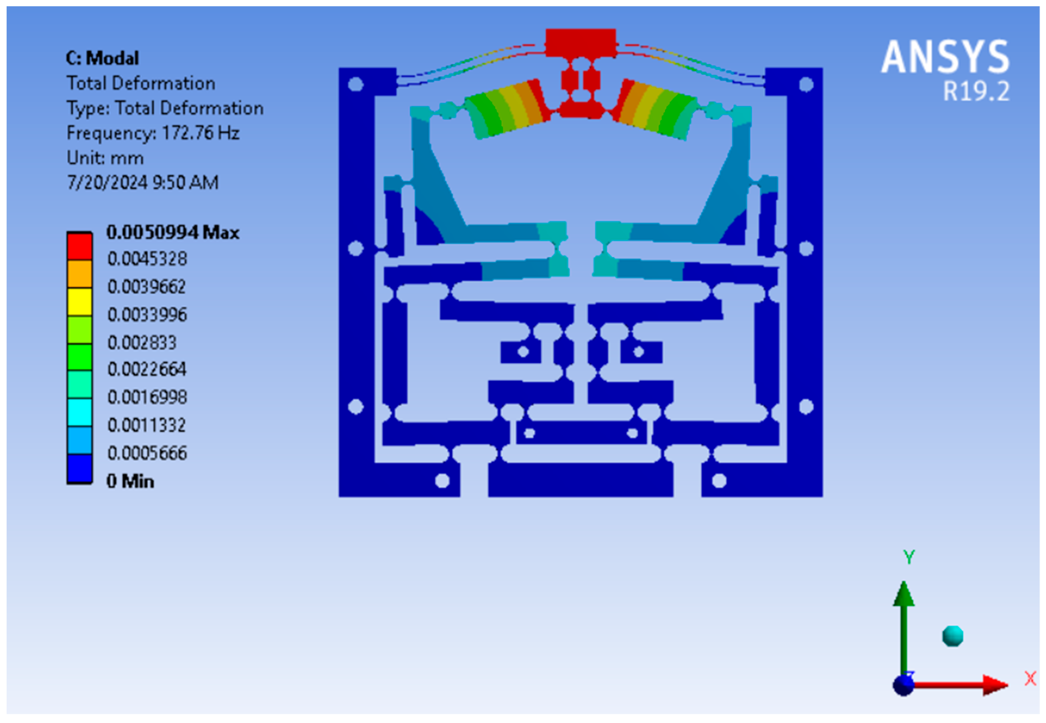
| (Hz) | 171.746 | 172.76 | 0.5869% |
| No. | Input Displacement | Output Displacement (Z-Direction) | Output Displacement (X-Direction) | Parasitic Motion Inaccuracy (%) |
|---|---|---|---|---|
| 1 | 2 | 13.6281 | 0.013 | 0.09539114 |
| 2 | 4 | 27.2562 | 0.0261 | 0.09562795 |
| 3 | 6 | 40.8843 | 0.0391 | 0.09562832 |
| 4 | 8 | 54.5125 | 0.0521 | 0.09562795 |
| 5 | 10 | 68.1406 | 0.0652 | 0.09562714 |
| 6 | 12 | 81.7687 | 0.0782 | 0.09562832 |
| 7 | 14 | 95.3968 | 0.0912 | 0.09562819 |
| 8 | 16 | 109.0249 | 0.1043 | 0.09562795 |
| 9 | 18 | 122.6530 | 0.1173 | 0.09562701 |
| 10 | 20 | 136.2811 | 0.1303 | 0.09562714 |
| 11 | 22 | 149.9093 | 0.1434 | 0.09562801 |
| 12 | 24 | 163.5374 | 0.1564 | 0.09562832 |
| 13 | 26 | 177.1655 | 0.1694 | 0.09562789 |
| 14 | 28 | 190.7936 | 0.1825 | 0.09562819 |
| 15 | 30 | 204.4217 | 0.1955 | 0.09562781 |
| 16 | 32 | 218.0498 | 0.2085 | 0.09562795 |
| 17 | 34 | 231.6779 | 0.2215 | 0.09562765 |
| 18 | 36 | 245.3061 | 0.2346 | 0.09562701 |
| 19 | 38 | 258.9342 | 0.2476 | 0.09562813 |
| 20 | 40 | 272.5623 | 0.2606 | 0.09562714 |
| 21 | 42 | 286.1904 | 0.2737 | 0.09562819 |
| 22 | 44 | 299.8185 | 0.2867 | 0.09562801 |
| 23 | 46 | 313.4466 | 0.2997 | 0.09562754 |
| 24 | 48 | 327.0747 | 0.3128 | 0.09562832 |
| 25 | 50 | 340.7029 | 0.3258 | 0.09562764 |
| 26 | 52 | 354.3310 | 0.3388 | 0.09562789 |
| 27 | 54 | 367.9591 | 0.3519 | 0.09562823 |
| 28 | 56 | 381.5872 | 0.3649 | 0.09562819 |
| 29 | 58 | 395.2153 | 0.3779 | 0.09562815 |
| 30 | 60 | 408.8434 | 0.3910 | 0.09562781 |
| Response | Optimized Theory Outcome | FEA Outcome | Imprecision |
|---|---|---|---|
| (Hz) | 220.16 | 198.86 | 9.67% |
| Attribute | Optimized Structure | Primary Structure | Enhancement |
|---|---|---|---|
| (Hz) | 198.86 | 172.76 | 13.12% |
| Attribute | FEA | Experiment | Inaccuracy |
|---|---|---|---|
| f (Hz) | 198.86 | 223.541 | 11.04% |
| Attributes | Present Study | Ref. [42] |
|---|---|---|
| Amplification ratio (FEA) | 6.8725 | 6.68 |
| Amplification ratio (experiment) | 8 | 6.5 |
| First natural frequency (FEA) | 198.86 | 203.37 |
| First natural frequency (experiment) | 223.541 | - |
Disclaimer/Publisher’s Note: The statements, opinions and data contained in all publications are solely those of the individual author(s) and contributor(s) and not of MDPI and/or the editor(s). MDPI and/or the editor(s) disclaim responsibility for any injury to people or property resulting from any ideas, methods, instructions or products referred to in the content. |
© 2025 by the authors. Licensee MDPI, Basel, Switzerland. This article is an open access article distributed under the terms and conditions of the Creative Commons Attribution (CC BY) license (https://creativecommons.org/licenses/by/4.0/).
Share and Cite
Dang, M.P.; Le, T.D.; Le, H.G.; Tran, C.T. Design and Optimization of a Novel Compliant Z-Positioner for the Nanoindentation Testing Device. Machines 2025, 13, 485. https://doi.org/10.3390/machines13060485
Dang MP, Le TD, Le HG, Tran CT. Design and Optimization of a Novel Compliant Z-Positioner for the Nanoindentation Testing Device. Machines. 2025; 13(6):485. https://doi.org/10.3390/machines13060485
Chicago/Turabian StyleDang, Minh Phung, Thanh Dat Le, Hieu Giang Le, and Chi Thien Tran. 2025. "Design and Optimization of a Novel Compliant Z-Positioner for the Nanoindentation Testing Device" Machines 13, no. 6: 485. https://doi.org/10.3390/machines13060485
APA StyleDang, M. P., Le, T. D., Le, H. G., & Tran, C. T. (2025). Design and Optimization of a Novel Compliant Z-Positioner for the Nanoindentation Testing Device. Machines, 13(6), 485. https://doi.org/10.3390/machines13060485