Abstract
The Dujiangyan–Siguniangshan mountain rack railway project is China’s first mountain rail transit. Most of its lines are located in mountainous areas and close to natural ecological protection areas, which have strict restrictions on the vibration and noise of train operation. At the same time, the vibration of mountain rack railway trains is also an important factor affecting the safety and riding comfort of trains. However, due to the multi-source vibration of gear teeth, wheels, rails, and suspensions, it is difficult to clearly define the vibration characteristics and vibration transmission path of the train, which has a serious impact on its vibration noise suppression and optimization. To this end, this study proposed a set of evaluation methods for the vibration characteristics and transfer paths of mountain rack trains based on a combination of dynamics and operational transfer path analysis (OTPA). Considering the interaction between the dynamic behaviors of the primary and secondary suspensions, the gear tooth contact behavior, the wheel–rail contact behavior and the dynamic behaviors of the track system, a dynamic model of a mountain rack train based on the finite element method was established, and the effectiveness of the model was verified through field experiments. On this basis, the OTPA method was used to establish a vibration transfer path model between the secondary suspension and the center of mass of the car body, and it was used to analyze the vibration mechanism and transfer path of the train body at the rated speed (20 km/h) and the limited speed (30 km/h). This study is of great significance for suppressing the vibration noise of mountain rack trains, reducing the impact on the ecological environment and improving ride comfort.
1. Introduction
A mountain rack train is a type of rail transit vehicle designed for steep mountain railways. It requires the installation of gears in the train running gear and the installation of racks in the corresponding tracks [1]. The meshing of the gears and racks avoids safety issues caused by insufficient wheel–rail adhesion under steep slope conditions and ensures the safe operation of trains on slopes of 480‰ [2]. To date, mountain rack trains have been widely used in mountain railways around the world due to their excellent climbing performances [3]. The Dujiangyan–Siguniangshan mountain rack train is China’s first new mountain rail transit system. The route passes through a natural ecological protection area. Exploring the intensity of vibration and noise of the gear meshing system unique to rack railways and their generation mechanism and laws is of great significance to reducing the impact on the ecological environment and improving ride comfort.
Vibration and noise are important factors affecting the service safety and ride comfort of mountain rack trains [4,5,6,7]. Therefore, knowing how to accurately analyze the dynamic behavior of mountain rack trains has attracted extensive attention from relevant scholars. Cheng et al. [8,9,10] considered the dynamic meshing excitation of the gear–rack and carried out a systematic study on the dynamic modeling method of mountain rack trains, thereby revealing the mutual influence mechanism between the gear–rack and wheel-track system, and explaining the influence of the time-varying meshing stiffness of the gear teeth and the polygonal wear of the wheel on the vibration characteristics of the vehicle body, which provides an important reference for the selection of design parameters and operating condition parameters of mountain rack trains. Cheng et al. [11,12] conducted targeted research on the coupled dynamic modeling method of mountain gear trains and tracks in response to the steep slope service environment of mountain gear trains and analyzed the influence of random track irregularities on the stability of train operation. On this basis, they further constructed a dynamic model of mountain gear trains, tracks, and bridges, and analyzed the gear meshing and wheel–rail contact characteristics of trains in extremely low temperature working conditions, providing important guidance for the early design and later operations and maintenance of mountain gear trains. Furthermore, the introduction of gear racks has prompted researchers to investigate the impact of their dynamic meshing excitation on the vibration characteristics of mountain rack rail trains [13,14]. The above dynamic research provides an important theoretical basis for analyzing the dynamic behavior of mountain gear trains. However, since the dynamic behavior of mountain gear trains is quite different from that of traditional rail trains, knowing how to accurately analyze the vibration transmission path of mountain gear trains is still a research difficulty in this field.
Operating transfer path analysis (OTPA) is a common method for vibration and noise transfer path analysis and source path contribution. It has been widely used in the vibration and noise analysis of traditional rail transit vehicles. Peng et al. [15] considered the combined influence of excitation amplitude and phase and used the OTPA method to analyze the vibration and noise transfer path of the subway, providing important theoretical guidance for subsequent vibration and noise suppression research. Song et al. [16] used the OTPA method to analyze the contribution of wheel–rail and frame vibration to the vibration and noise of high-speed train bogies, providing a theoretical reference for the vibration reduction and noise reduction research of high-speed trains. Gao et al. [17] analyzed the vibration and noise transfer path between the suspension system, the pantograph system, and the train body. According to the above research, it is not difficult to see that the OTPA method can effectively establish the vibration transfer path between multiple vibration sources and the target point, so as to accurately analyze the vibration contribution of different vibration sources to the target point, providing an important theoretical basis for subsequent vibration and noise suppression.
In this study, a method combining dynamic modeling with the OPTA approach is proposed to analyze the vibration characteristics and vibration transfer paths of mountain rack trains, aiming to support vibration and noise optimization. The method involves developing a high-precision dynamic model that incorporates the behaviors of the primary and secondary suspensions, gear tooth contacts, wheel–rail interactions, and track dynamics to accurately capture the full-vehicle dynamic responses. Based on this model, the vibration signal of the train’s secondary suspension is treated as the vibration source, and the vehicle body’s center of mass is defined as the target point. The vibration transfer path between the source and target is then constructed using the OPTA method to effectively analyze each source’s contribution to the vibration at the target point. This provides theoretical support for future vibration and noise optimization in mountain rack trains. While previous studies have examined the vibration and noise behaviors of mountain rack trains in detail [8,9,10,11,12], they primarily focus on local phenomena such as gear–rack and wheel–rail interactions. Few studies address the dynamic behaviors of the entire train system, and the OPTA method has not been applied to analyze its vibration transfer paths.
The subsequent research of this paper is as follows: Section 2 established a dynamic model that considers the multi-source vibration effects of gear teeth, wheel rails, and suspension, and verified the effectiveness of the model through experiments; Section 3 used the secondary suspension of mountain rack trains as the vibration source and the center of mass of the car body as the target point, and used the OTPA method to establish a vibration transmission path model between the vibration source and the target point; in Section 4, the established vibration transmission path model was used to analyze the body vibration mechanism and transmission path of the train at the rated speed (20 km/h) and the limit speed (30 km/h); and finally, the conclusion was given in Section 5.
2. Dynamic Modeling and Verification of Mountain Rack Trains
In this section, a high-precision dynamic model of mountain rack trains is established, and its effectiveness is verified through field tests, thus laying the foundation for the vibration characteristics and transfer path analysis of mountain rack trains.
2.1. Description of the Dynamic Modeling Process of Mountain Rack Trains
In this subsection, based on the mountain rack train-track coupled dynamics theory [9], the dynamic modeling framework of the mountain rack train is first proposed, and the dynamic models of the track system and the car body system are completed in sequence through the Abaqus software (2022), finally forming a complete mountain rack train-track coupled dynamics model.
2.1.1. Dynamic Modeling Framework of Mountain Rack Trains
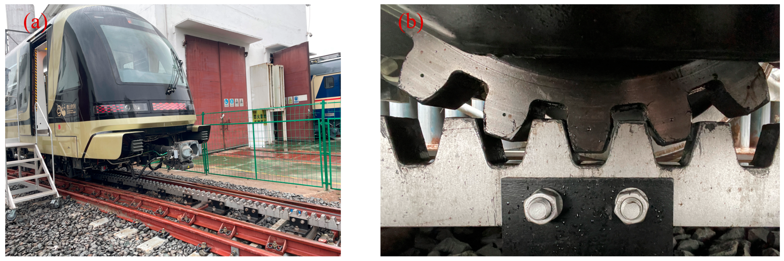
This study originates from the Dujiangyan–Siguniangshan mountain rack train project. As shown in Figure 1, it is the rack test line of this project in Ziyang City, Sichuan Province (the driving slope is 120‰, the rated driving speed is 20 km/h, and the maximum driving speed is 30 km/h). The track form is a ballasted track, and a single carriage is equipped with a traction gear. The gear–rack adopts the Strub standard [18]. The specific gear–rack design parameters are shown in Table 1.

Figure 1.
Mountain rack train test line: (a) mountain rack train; (b) gear–rack traction system.

Table 1.
Gear rack design parameters.
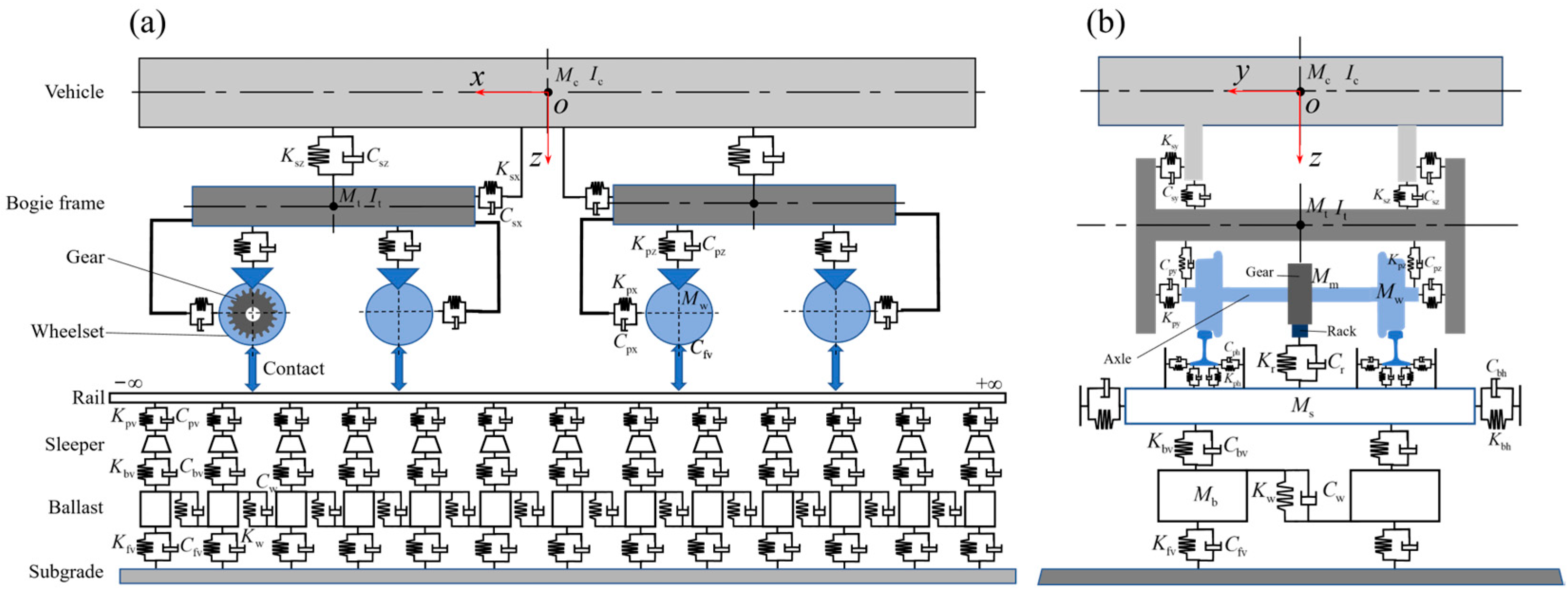
According to the working condition parameters of the test line and the related research of mountain gear trains [19,20,21], the train-track coupling dynamics models as shown in Figure 2 can be established. The model mainly consists of two parts: the track system and the car body system, where the behavior between the rail–wheel and track-rack is considered as a real contact relationship, while the suspension system, ballast, fasteners, sleepers, etc., are simplified into stiffness and damping. The parameters in Figure 2 are explained in detail in Table 2.
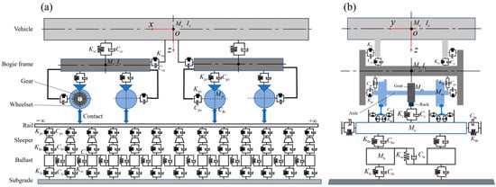
Figure 2.
Mountain rack train-track coupling dynamics model: (a) front view, (b) side view.
Table 2.
Relevant parameters of mountain rack train dynamic mode.
2.1.2. Vehicle System Dynamics Model
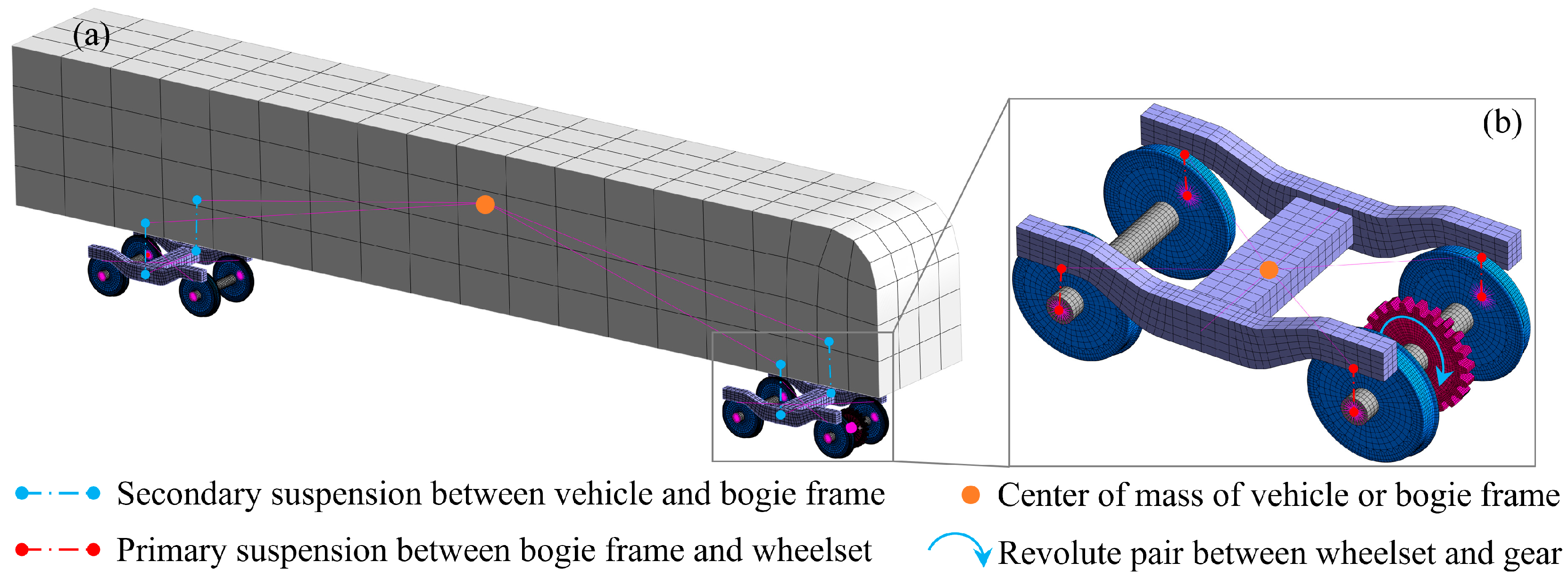
According to the on-site vehicle parameters shown in Figure 1, a single train consists of a car body, four sets of secondary suspensions, two sets of bogies, eight sets of primary suspensions, four sets of wheel pairs, and one traction gear. Combined with the vehicle system dynamics modeling ideas described in Figure 2, a dynamic model, as shown in Figure 3, can be established in the Abaqus software following the approach proposed by Liu [21,22,23,24,25,26]. The car body and bogie, and the bogie and wheel pairs, are connected by secondary suspension and primary suspension, respectively. In this study, they are simplified into longitudinal, lateral, and vertical stiffness and damping systems; and the wheel pairs and gears are connected by setting a rotating pair [27]. The specific parameters of stiffness and damping between the various parts in the vehicle systems dynamics model are shown in Table 3.
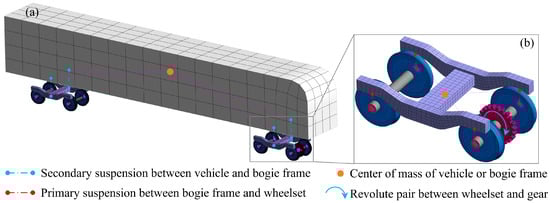
Figure 3.
Vehicle system dynamics model: (a) vehicle model, (b) running gear model.
Table 3.
Stiffness and damping parameters of vehicle system dynamics model.
In addition, considering the calculation accuracy and efficiency of the model, the car body and bogie are set as rigid bodies, and the meshing is completed using quadrilateral shell elements. The mass and moment of inertia that are consistent with the actual situation are set at the center of mass of the model, as shown in Table 4. The wheel pair and a traction gear are set as flexible bodies, and the meshing is completed using hexahedral mesh elements. The entire vehicle system dynamics model contains a total of 151,683 meshes and 212,164 nodes.
Table 4.
Mass and moment of inertia parameters of vehicle system dynamics model.
2.1.3. Track System Dynamics Model
As shown in Figure 1, the track form of the mountain rack train in the test line is a ballasted track. In transmission rail transit, a ballasted track is mainly composed of the track, sleeper, fastener, ballast, roadbed, and other parts. In the mountain rack train track system, it is necessary to add racks on the sleepers. For transmission rail transit, the finite element dynamic modeling method of its track system is relatively mature. According to the literature [8], the fasteners and ballast are simplified into a stiffness and damping system. For this study, due to the additional introduction of the rack, it is also necessary to set the stiffness and damping relationship between the sleeper and the rack. The final track system dynamic model is shown in Figure 4. The model is divided by full hexahedral mesh units, with a total of 407,022 meshes and 576,087 nodes. The specific parameters of stiffness and damping between the various parts in the track system dynamic model are shown in Table 5.
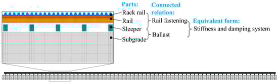
Figure 4.
Track system dynamics model.
Table 5.
Stiffness and damping parameters of track system dynamics model.
2.1.4. Dynamic Model of Mountain Rack Train
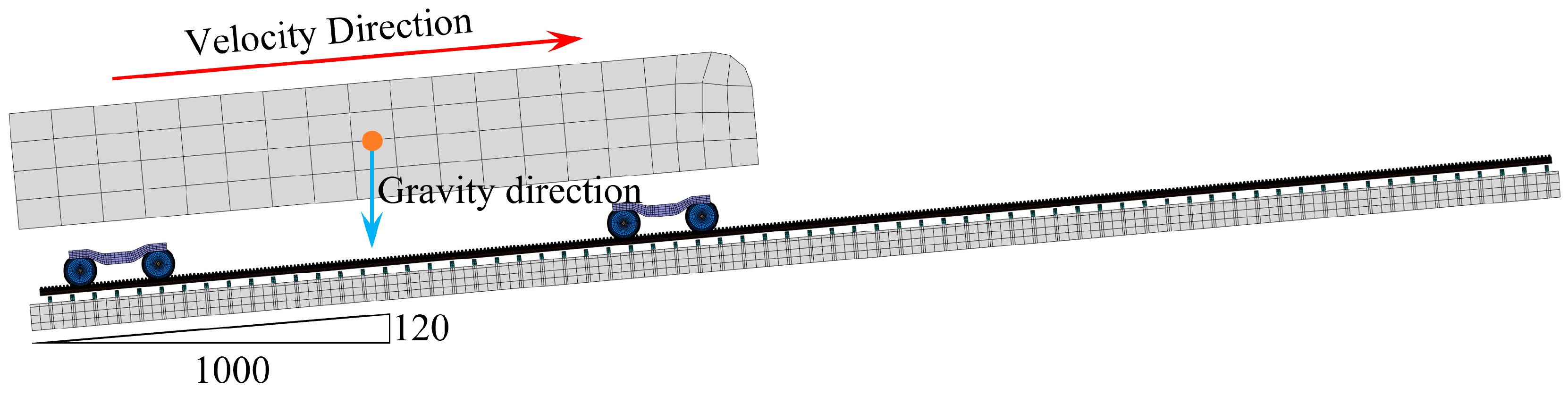
The complete dynamic model of mountain rack trains also needs to complete the coupling of vehicle and track system dynamic models, and the application of motion and load conditions. The model coupling relationship mainly includes the contact relationship between the wheel–rail and gear–rack, which can be implemented in Abaqus software using Hertz contact relationship; the application of the motion condition is achieved by applying the rotation speed in the gear rotating pair; and the application of load conditions mainly comes from the component force of the train’s own weight along the track direction, which is achieved by adjusting the angle between the gravity direction and the track direction. As shown in Figure 5, a complete dynamic model of a mountain rack train is given.
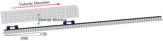
Figure 5.
Finite element model of mountain rack train.
In particular, since the dynamic model of the mountain rack train is a complex nonlinear system, the sudden application of motion and load will cause the numerical solution process to diverge, so the simulation process needs to be set into two stages: the first stage is the balance stage, under the condition of constraining the rotation of the gear, the balance of the system displacement and contact state is achieved through external loads. The second stage is the loading stage, that is, the rotation speed is applied to the gear rotation pair to analyze the dynamic characteristics of the train. In this study, all models are calculated using the hardware environment of CPU: I7 13700k, GPU: 3060TI, and memory: 4 × 32 GB.
2.2. Model Validation and Verification
In order to verify the effectiveness of the dynamic modeling of mountain rack trains established in Section 2.1, the wheel–rail lateral and vertical force test method described in TB/T2489-2016 Ground Test Method for Wheel-Rail Lateral and Vertical Forces [27] was used to test the vertical force of the train at different speeds on the rack test line in Ziyang city, Sichuan Province, and the dynamic model analysis results were compared.
As shown in Figure 6, the arrangement of strain gauges for measuring the lateral and vertical forces of the track, the test principle, and the test site are shown. The lateral and vertical forces between the wheel and rail are measured using the shear method. The procedure is as follows: First, according to the test standard [27], strain gauges are affixed at appropriate positions on the wheel–rail system. Second, the strain gauges for measuring the lateral and vertical forces are configured into full-bridge circuit and carefully leveled. Finally, varying loads are applied in the lateral and longitudinal directions of the wheel–rail according to a predefined gradient to establish the relationship between the applied forces and the strain readings. This relationship is then used to calibrate the testing system. Upon completion of these steps, the lateral and vertical forces generated during train operation can be accurately measured.
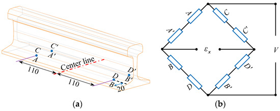
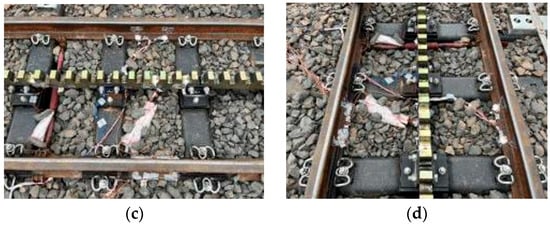
Figure 6.
Wheel–rail force test method: (a) strain gauge layout; (b) test principle; (c) vertical force test site; (d) lateral force test site.
As shown in Figure 7, we tested the wheel–rail lateral force and vertical force of the mountain rack train at 10, 20, and 30 km/h on site, and compared them with the dynamic model simulation results. By comparing the field measured data and simulation data, it can be seen that the maximum error of the wheel–rail vertical force occurs when the train speed is 30 km/h, with a relative error of 3.2%; the maximum error of the wheel–rail lateral force occurs when the train speed is 20 km/h, with a relative error of 4.6%. The errors of all simulation and test results are less than 5%, which is within a reasonable range, which shows the effectiveness of the established mountain rack train dynamic model.
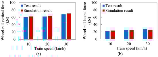
Figure 7.
Comparison of simulation and test results at different speeds: (a) average wheel–rail vertical force; (b) average wheel–rail lateral force.
3. Modeling and Verification of Vibration Transfer Paths of Mountain Rack Trains
In this section, we first briefly describe the basic principles of the OTPA method, and based on the mountain rack train dynamics model created in Section 2, we establish a vibration transfer path model between the primary suspension of the train and the center of mass of the vehicle body to analyze the vibration contribution and transfer path of each primary suspension of the train to the center of mass of the vehicle body.
3.1. Basic Theory of OTPA
OTPA is a commonly used analysis method for vibration transfer paths and contribution rates and has been widely used in the fields of rail transit and automobiles [28,29,30,31]. In the OTPA method, the target point vibration is obtained by linearly superimposing the vibration of the excitation source along each transfer path to the target point. Assuming that the number of measurement conditions is m, the number of excitation sources is n, and m > n, the OTPA model can be expressed as follows [32]:
where Ym represents the output response corresponding to the mth working condition, Xmn represents the response of the nth excitation source corresponding to the mth working condition, and Hn represents the vibration transmissibility of the nth excitation source. Equation (1) can be further simplified as follows:
where Y is the output response matrix of the target point, X is the input response matrix of the stimulus source, and H the transfer function matrix.
Furthermore, in order to avoid the influence of crosstalk between the vibration signals of the excitation resources on the calculation accuracy, it is necessary to perform singular value decomposition (SVD) on the input response matrix X to obtain a series of linearly independent principle component vectors, and then form a principal component space [28], which can be expressed as follows:
where U and V are the singular matrices of X, both of which are unitary matrices; and S is the singular value matrix of X, which can be expressed as follows:
In the equation, the elements of σi in the diagonal represent the singular values of X. the larger singular values correspond to the main components in the vibration signal of the excitation source, while the smaller singular values correspond to the secondary components in the vibration signal of the excitation source. Related studies [33] have shown that the reasonable discarding of smaller singular values can help reduce the impact of measurement noise on the calculation of the transfer matrix, thereby improving the accuracy of the model. This study refers to reference [34] and adopts the Pareto principle to retain only 20% of the elements in the diagonal of S, and the sum of these 20% elements accounts for about 80% of the sum of all diagonal elements. The singular value matrix after removing the smaller singular values is denoted as Sr, and the corresponding input response matrix X can be expressed as follows:
After substituting Equation (5) into Equation (2), the transfer function matrix after SVD can be expressed as follows:
In the equation, represents the transfer function matrix calculated after SVD. Finally, we can synthesize the output response of the target point () through and X as follows:
3.2. OTPA Modeling and Verification of Mountain Rack Trains
In this section, according to the OTPA modeling processes, a vibration transfer path model between the primary suspension and the center of mass of the mountain rack train was established, and its effectiveness was verified by comparing it with the dynamic model, thus laying the foundation for the subsequent analysis of the vibration characteristics and transfer path of the mountain rack train.
3.2.1. Modeling and Description of Vibration Transfer Paths of Mountain Rack Trains
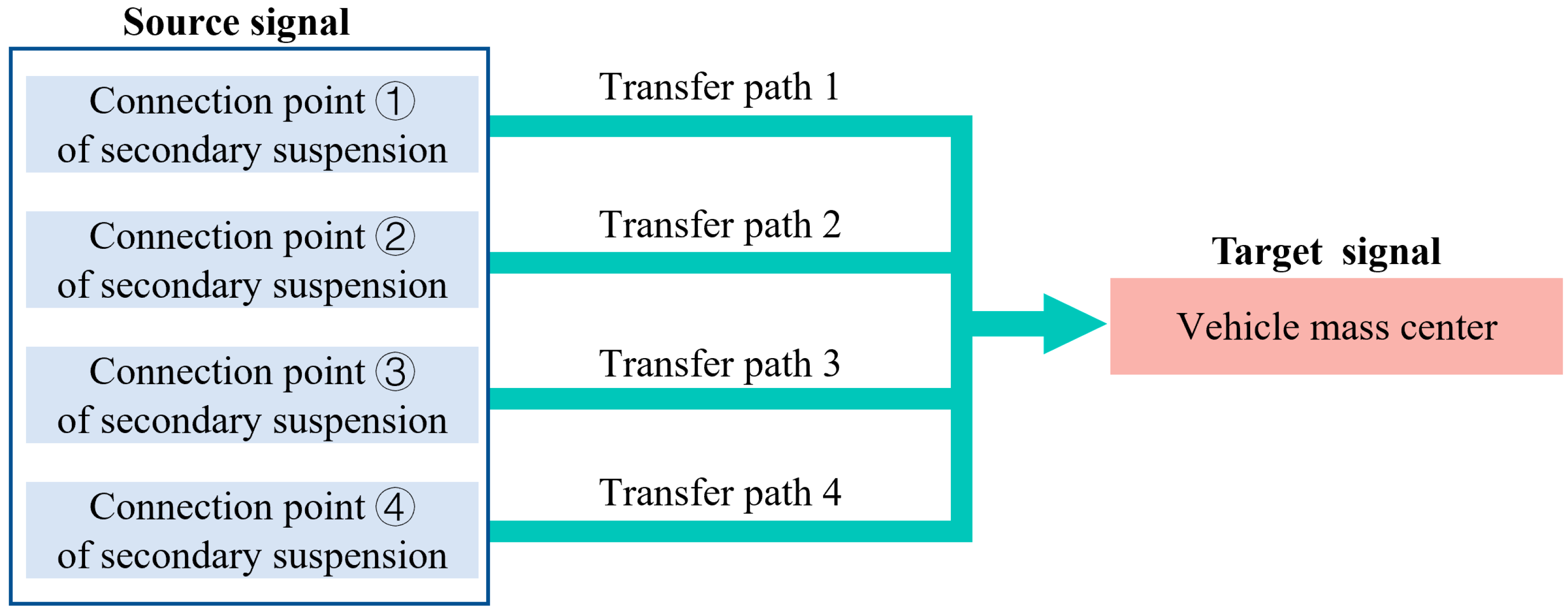
The vibration of mountain rack trains during operation mainly comes from the impact vibration generated by the contact between wheels and rails and the meshing between gears and racks [8,9,10,11,12] and is transmitted to the car body through the primary suspension, bogie system, and secondary suspension in sequence. The vibration transmission path is shown in Figure 8. According to Section 3.1, the OTPA modeling process must ensure that the number of working conditions used for modeling is greater than the number of excitation source signals. If the vibration generated by the wheel–rail and rack is directly used as the vibration source signal (eight wheel–rail vibration signals and one gear–rack vibration signal), the number of working conditions used for modeling is at least 10, and the calculation amount and modeling difficulty are both large. Therefore, we use the vertical vibration acceleration of the connection between the four secondary suspensions and the bogie as the vibration source signal, and the vertical vibration acceleration at the center of mass of the car body as the target point signal, thereby simplifying the modeling calculating amount of the OTPA model. The specific modeling process is shown in Figure 9.
Figure 8.
Vibration transmission path of mountain rack train body.

Figure 9.
OTPA modeling process.
3.2.2. Validation of the OTPA Model
According to the modeling process shown in Figure 9, we use train speeds of 15, 17.5, 22.5, 27.5, 32.5, and 35 km/h as calculation conditions, the dynamic model to calculate the vertical vibration of the secondary suspension under the corresponding conditions, and calculate the vibration transfer function matrix between the secondary suspension and the center of mass of the car body through Equation (6), thus completing the OTPA modeling process.
Furthermore, to verify the validity of the established model, the conditions of the train rated speed (20 km/h) and the limit speed (30 km/h) were selected, and the vertical acceleration of the center of mass of the vehicle body was synthesized by the OTPA model and compared with the dynamic calculation results. In particular, we converted the vibration acceleration (m/s2) into the vibration acceleration level (dB) for analysis, which can be expressed as follows:
In the equation, La (dB) represents the vibration acceleration level, a (m/s2) represents the effective value of vibration acceleration, and a0 = 10−6 m/s2 denotes the reference acceleration value, which is based on the design standard GB50894-2013 Environmental Protection Design Specifications for Machinery Industry [35].
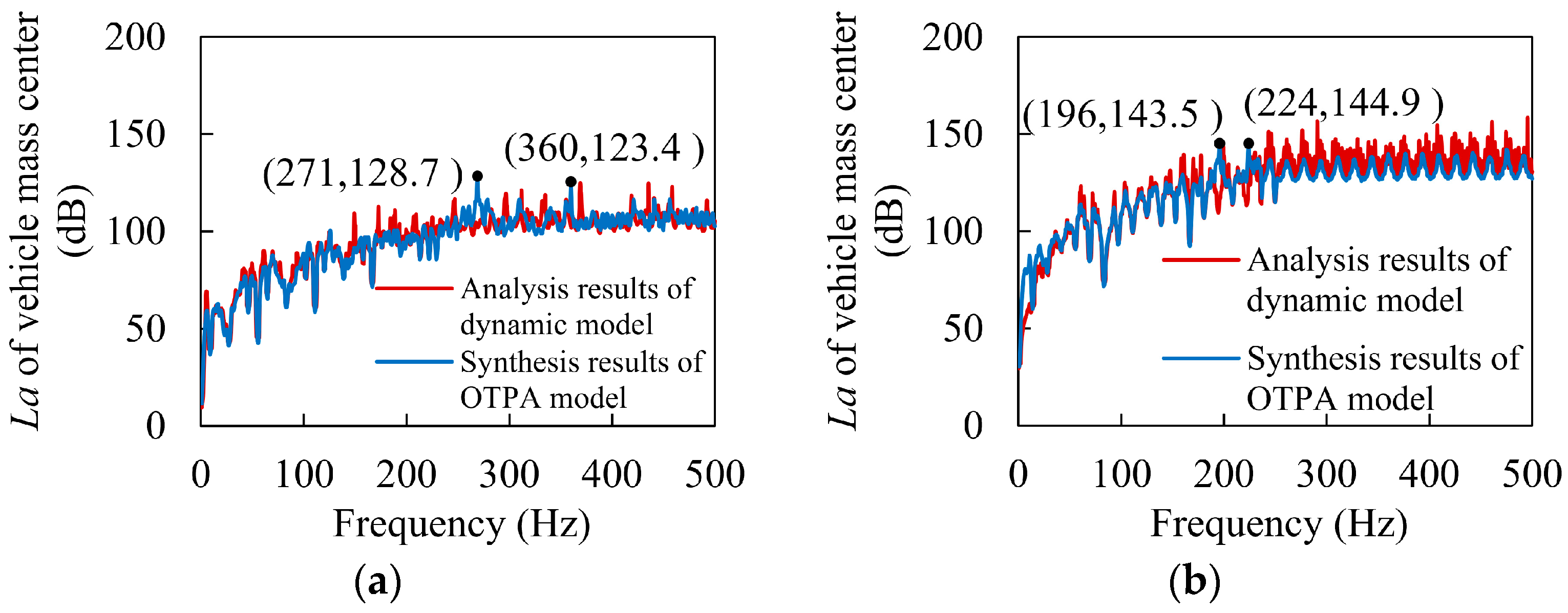
The analysis results are shown in Figure 10. The OTPA model synthesis results are consistent with the dynamic model calculation results, which can illustrate the effectiveness of the established model. In addition, it can be seen from the figure that the OTPA synthetic signal has peak frequencies at 271 Hz and 360 Hz in Figure 10a and 196 Hz and 360 Hz in Figure 10b. The causes of these peak frequencies should be analyzed in detail in Section 4.
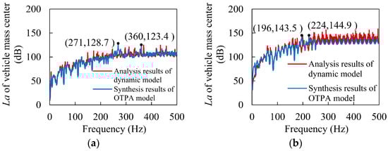
Figure 10.
Comparison of simulated signal and synthetic output signal (a) 20 km/h, (b) 30 km/h.
4. Analysis of Vibration Characteristics and Transmission Paths of Mountain Rack Trains
In this section, the established OTPA model of mountain rack railway trains is used to quantitatively analyze the vibration contribution rate of various excitation source signals to the center of mass of the train body when the train is running at rated speed (20 km/h) and limit speed (30 km/h), so as to provide a theoretical reference for the suppression of car body vibration noise.
4.1. Analysis of Vibration Mechanism and Transmission Path at Rated Speed
The rated speed of the Dujiangyan–Siguniangshan mountain rack train is 20 km/h. Analyzing the vibration mechanism and transmission path of the train under rated conditions is of great guiding significance for ensuring the train ride comfort and conducting noise reduction research. As shown in Figure 10a above, the vibration acceleration of the train under this condition is less than 130 dB, which is in a relatively low range, ensuring that passengers in the car have a good riding experience. However, the vibration acceleration levels at 271 Hz and 360 Hz are relatively large and should be further analyzed.
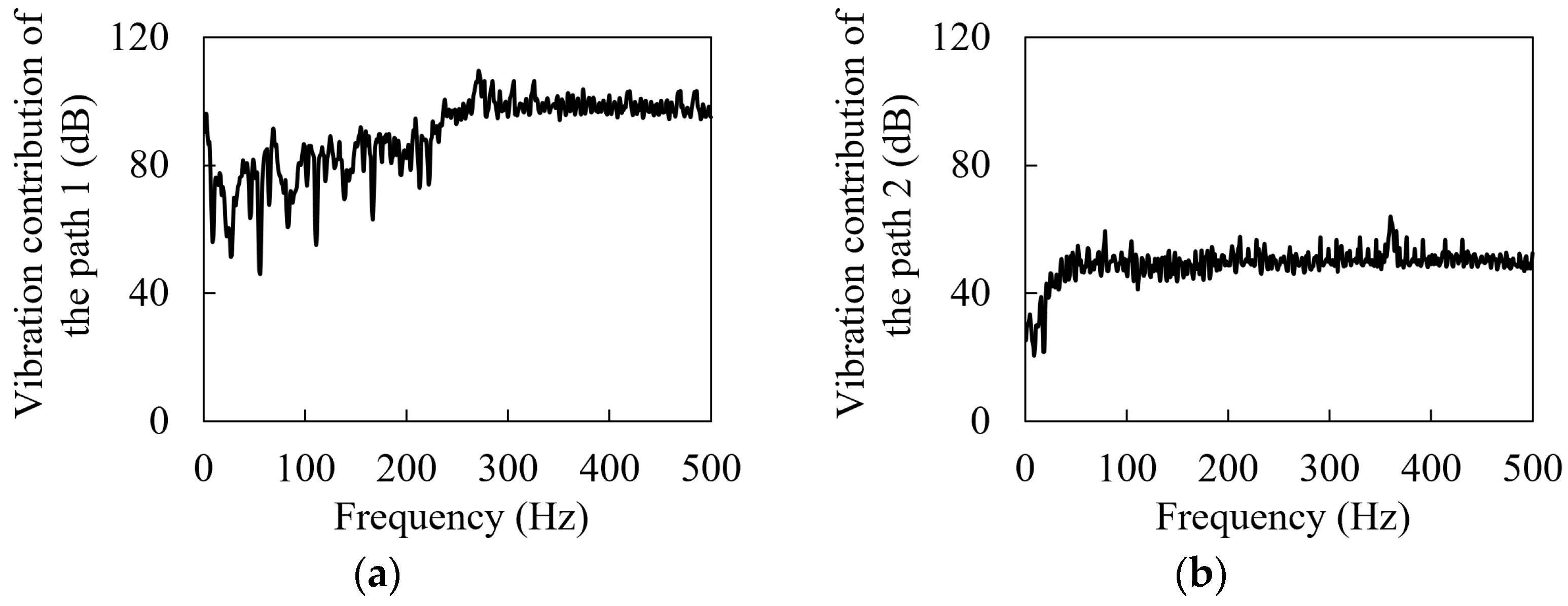
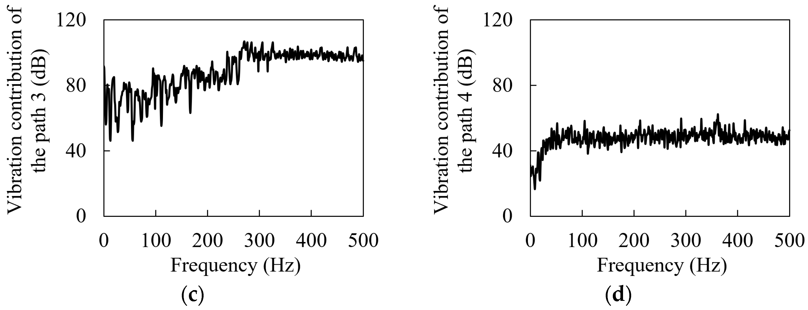
As shown in Figure 11, the vibration contribution spectra of the four transmission paths are given, respectively. It can be seen from the figure that due to the existence of gear–rack meshing as the excitation source in transmission paths 1 and 3, the contribution of transmission paths 1 and 3 to the vibration noise of the target point is much greater than that of transmission paths 2 and 4. For transmission paths 1 and 3, before the frequency of 270 Hz, the vibration contribution fluctuates from 50 dB to 100 dB, and then between 270 Hz and 500 Hz, the vibration contribution slowly decreases from the maximum peak of 109.53 dB and then tends to be stable, roughly around 100 dB. For transmission paths 1 and 3, the vibration contribution shows an exponential upward trend between 0 and 50 Hz, and then tends to be stable, and a peak frequency appears at 360 Hz. From the change in the vibration contribution of the four transmission paths. It can be seen that the vibration at the frequency of 271 Hz in Figure 10a mainly comes from paths 1 and 3, while the vibration at the frequency of 360 Hz is the result of the joint influence of the four paths.

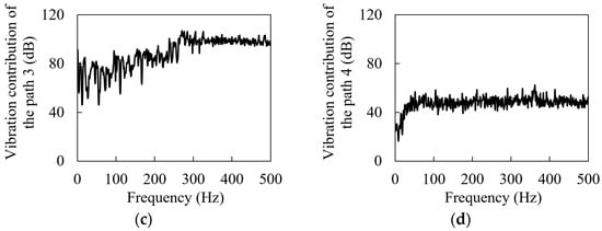
Figure 11.
Vibration contribution spectra of the transmission paths: (a) Path 1, (b) Path 2, (c) Path 3, (d) Path 4.
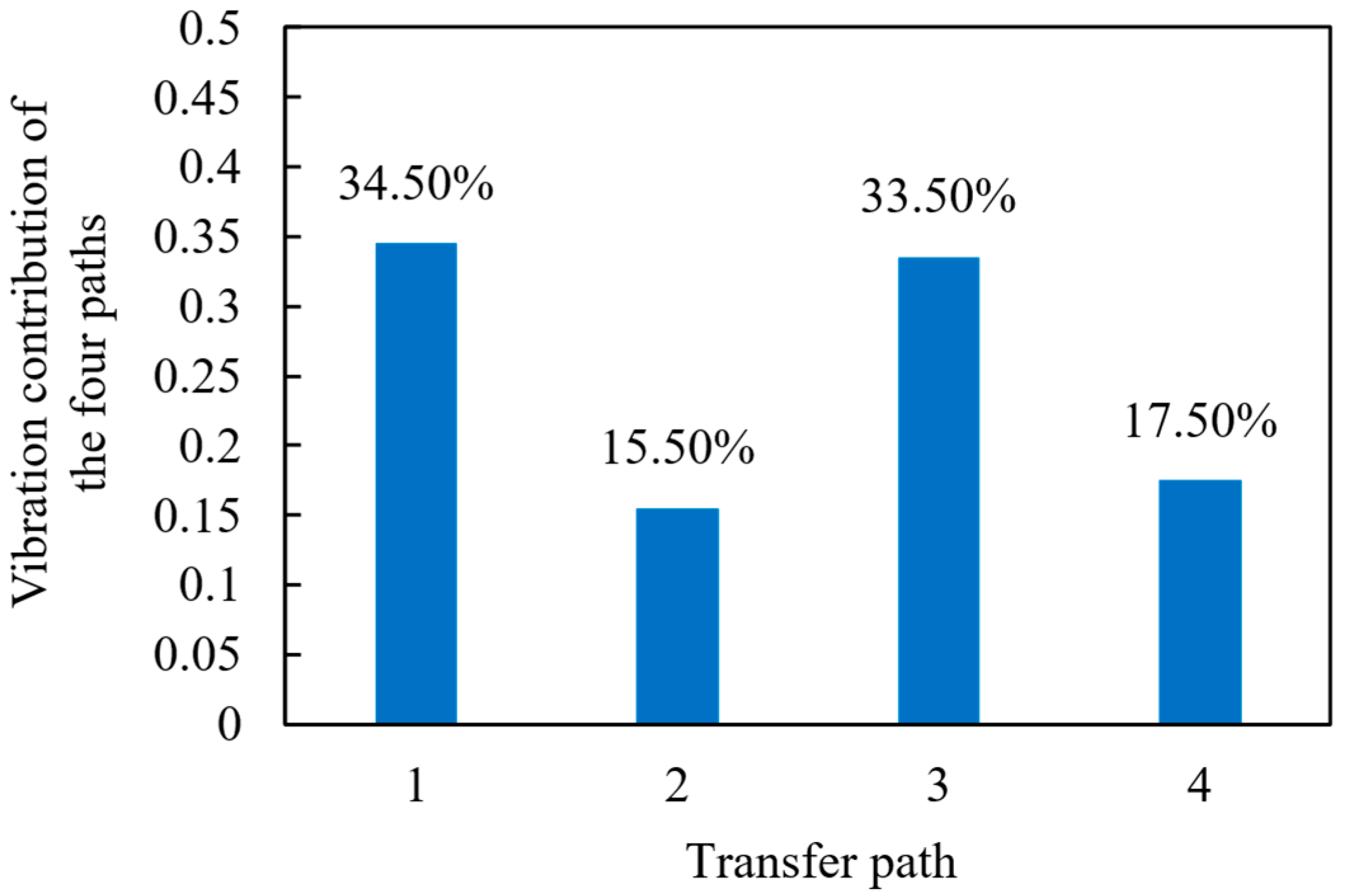
Furthermore, according to reference [32], the corresponding vibration contribution can be calculated based on the vibration contribution spectrum of each transmission path, as shown in Figure 12. As can be seen from the figure, paths 1 and 3 contribute the most to the train body vibration, which are 34.53% and 33.52%, respectively, while the contributions of paths 2 and 4 are relatively small, which are 17.45% and 15.5%, respectively. Therefore, when optimizing the vibration and noise of mountain rack trains, we should focus on paths 1 and 3, especially the vibration reduction and noise reduction analysis of the gear–rack meshing system.
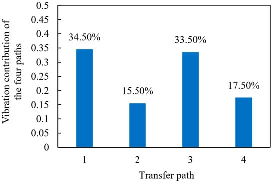
Figure 12.
Vibration contribution of the four transmission paths at rated speed.
4.2. Analysis of Vibration Mechanism and Transmission Path at Extreme Speed
The maximum speed of the Dujiangyan–Siguniangshan mountain rack train is 30 km/h. As shown in Figure 10b above, the maximum vibration acceleration level of the train under this condition is 143.5 dB, which is higher than the rated speed, and the passengers’ riding experience may be poor. According to Section 4.1, the meshing vibration of the gear and rack is a key factor affecting the vibration noise of the train. As the rain speed increases, the meshing vibration of the gear and rack will increase. Therefore, we should focus on the vibration contribution of paths 1 and 3 and pay special attention to the vibration contribution at the frequencies of 196 Hz and 224 Hz.
Considering that the vibration contribution of paths 2 and 4 is relatively small, only the vibration contribution spectrum of transmission paths 1 and 3 is given in Figure 13. As can be seen from the figure, when the frequency is lower than 300 Hz, the vibration contribution fluctuates from 70 dB to 139.34 dB, and the amplitude fluctuates greatly. The peak appears at 195 Hz and the secondary peak appears at 223 Hz. Then, between 300 Hz and 500 Hz, the vibration contribution slowly decreases from the maximum peak of 129.53 dB and then stabilizes, remaining at around 110 dB. In addition, it can be seen from Figure 13a that within the frequency range of 195 Hz to 223 Hz, there are two peak frequencies in the vibration contribution spectrum of transmission path 1, which coincide with the frequencies of 196 Hz and 224 Hz in Figure 10b. It can be considered that transmission path 1 is the main reason for the peak frequencies of 196 Hz and 224 Hz in Figure 10b.
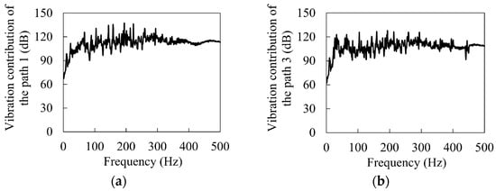
Figure 13.
Vibration contribution spectra of the transmission paths: (a) path 1, (b) path 3.
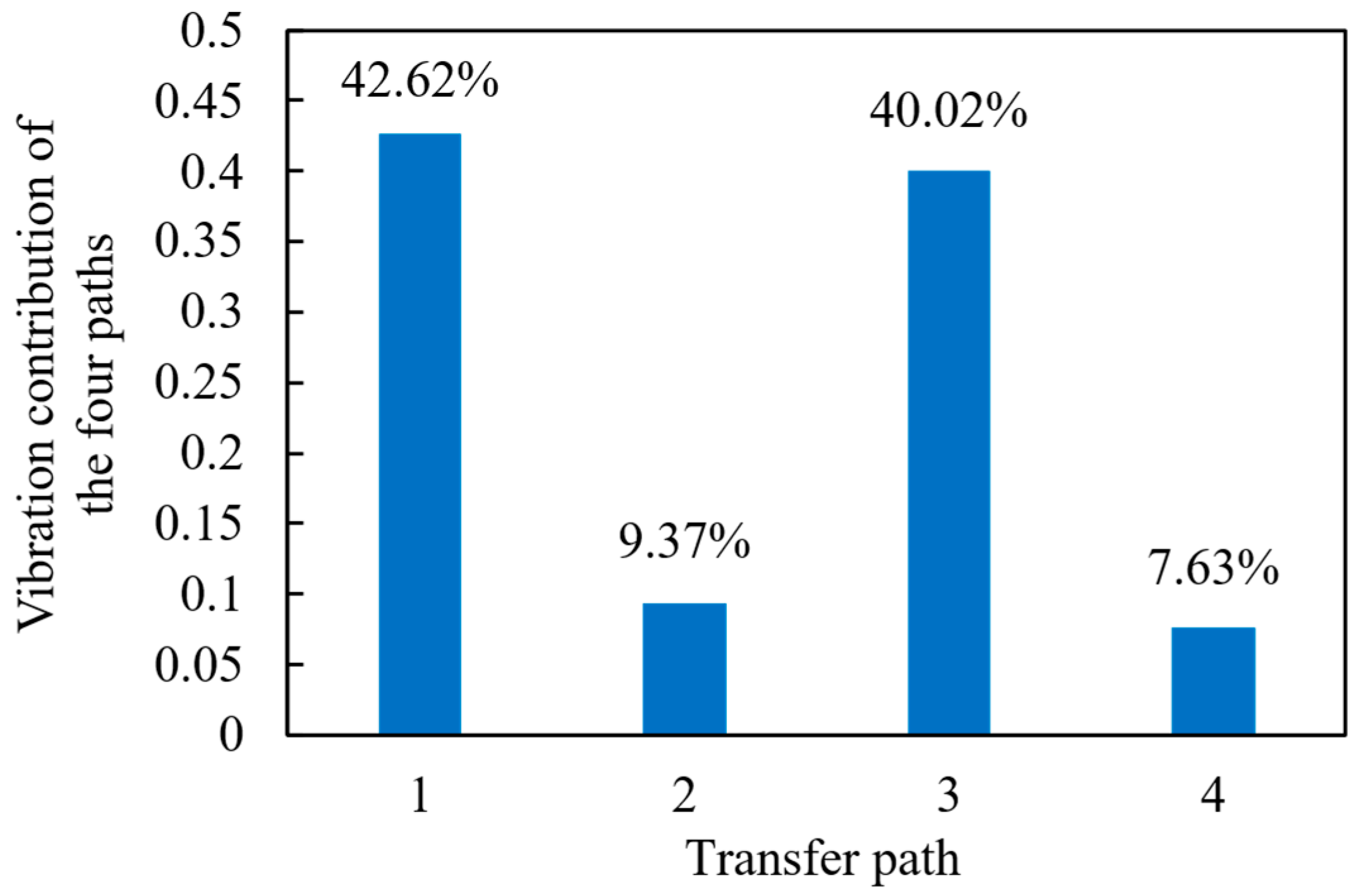
Similarly, we show in Figure 14 the vibration contribution calculated based on the vibration contribution spectrum of each transmission path. Compared with the rated speed result, the contribution of transmission paths 1 and 3 is significantly increased, and the contribution of transmission paths 2 and 4 is significantly reduced, among which the contribution of transmission paths 1 and 3 is 42.62% and 40.02%, respectively, and the contribution of transmission paths 2 and 4 is 9.37% and 7.63%, respectively. This result further shows that when optimizing the vibration and noise of mountain rack trains, we should focus on transmission paths 1 and 3, especially in the gear–rack meshing system for vibration reduction and noise reduction analysis.
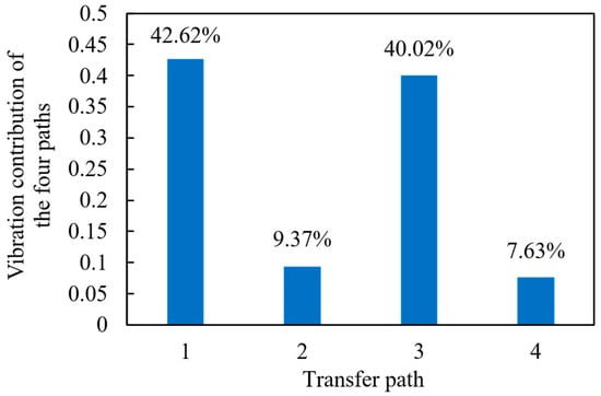
Figure 14.
Vibration contribution of the four transmission paths at the limit speed.
5. Discussion
According to the analysis presented earlier, the vibration contribution rates of route 1 and route 3 are significantly higher than those of route 2 and route 4. The primary factor leading to this result is the dynamic meshing excitation of the gear–rack system. Therefore, in this section, the dynamic characteristics of the gear–rack system are analyzed using the established dynamic model of a mountain rack rail train, under both the rated speed (20 km/h) and the maximum speed (30 km/h). Furthermore, the mechanism by which the gear–rack system generates vibration and noise in mountain rack rail trains is discussed, providing a theoretical reference for analyzing the sources of car body vibration and noise, as well as for developing noise suppression strategies.
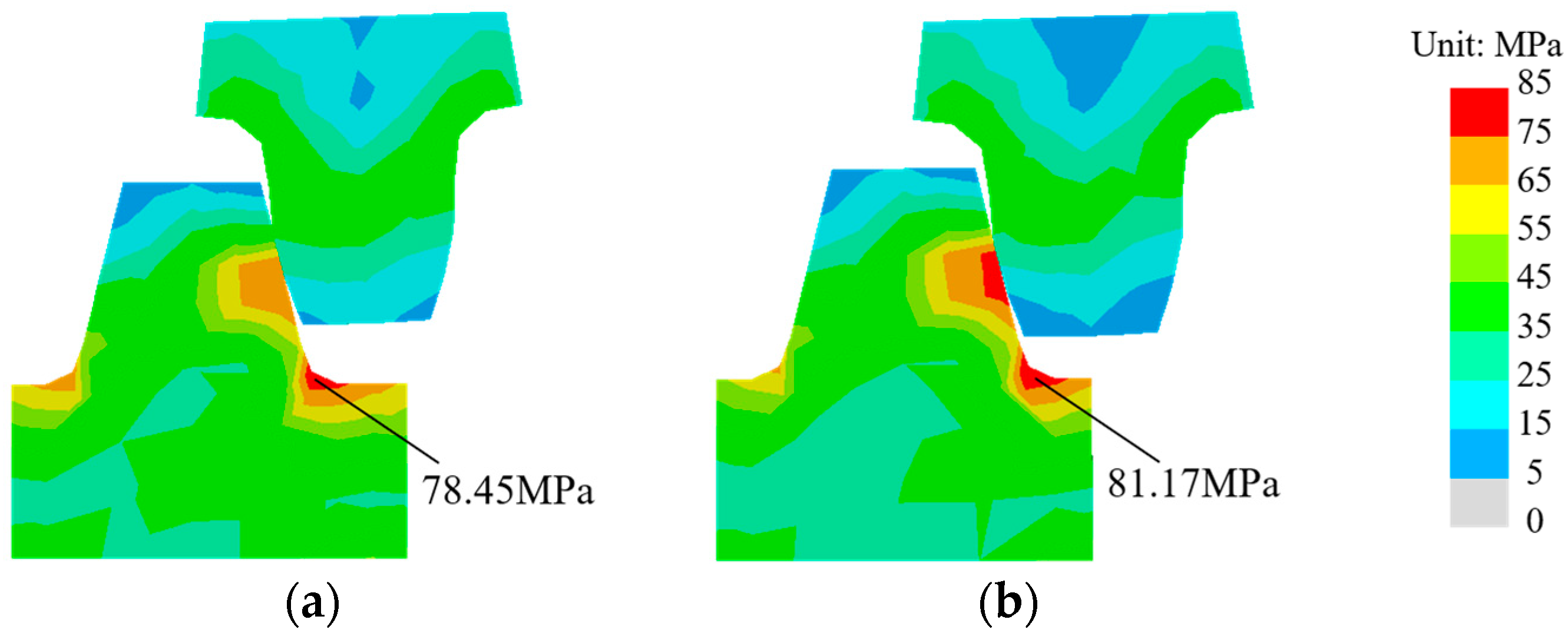
Figure 15 illustrates the contact stress contour plots of the gear–rack system at the rated speed (20 km/h) and the maximum speed (30 km/h). The maximum contact stress occurs at the root of the rack teeth in both cases, with values of 78.45 MPa and 81.17 MPa, respectively. The variation in the contact load is shown in Figure 16a,b. It can be observed that the contact load between the gear and the rack exhibits periodic fluctuations. This is due to the gear undergoing a meshing cycle that transitions from double-tooth contact to single-tooth contact and then back to double-tooth contact, resulting in a period variation in the contact load. Numerically, the average contact loads of the gear–rack system at the rated and maximum speeds are 55.19 kN and 62.73 kN, respectively, indicating a positive correlation between the contact stress and the train’s operating speed.

Figure 15.
Contact stress contour plot of the gear–rack system: (a) 20 km/h, (b) 30 km/h.
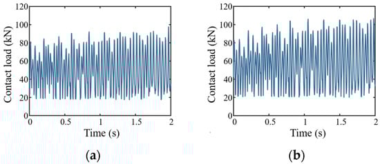
Figure 16.
Variation in contact load between the gear and rack: (a) 20 km/h, (b) 30 km/h.
Figure 17 illustrates the variation in vibration acceleration of the gear–rack system at the rated speed (20 km/h) and the maximum speed (30 km/h). As shown in the figure, due to the periodic variation in the meshing state, the vibration acceleration of the gear–rack system exhibits a similar pattern of periodic fluctuation as the contact stress. Numerically, the average vibration accelerations at the rated and maximum speeds are 34.93 m/s2 and 41.97 m/s2, respectively, indicating that the vibration intensity of the gear–rack system increases with train speed. Moreover, the increase in gear–rack vibration leads to greater vibration contributions from transmissions routes 1 and 3. This trend is consistent with the analysis results presented in Section 4, where the vibration contributions of routes 1 and 3 were shown to increase with train operating speed.
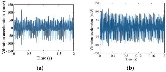
Figure 17.
Variation in vibration acceleration of the gear–rack system: (a) 20 km/h, (b) 30 km/h.
6. Conclusions
The Dujiangyan–Siguniangshan mountain rail is China’s first mountain rail transit project. Its route passes through a natural ecological protection area and has strict requirements on the vibration and noise of mountain rack trains. The multi-source vibration influence of gear teeth, wheel rails, and suspension makes it difficult to clarify the vibration characteristics and vibration transmission paths of mountain rack trains. To this end, this paper proposes a set of mountain rack train vibration characteristics and transmission path evaluation methods based on the combination of dynamics and transmission path analysis. On the basis of verifying the effectiveness of the model, the body vibration mechanism and transmission path of a certain type of mountain rack train are explored, which is of great significance to reducing the impact on the ecological environment and improving passenger comfort. The main conclusions are summarized as follows:
- (1)
- Considering the interaction between the primary and secondary suspension dynamics behaviors, gear tooth contact behaviors, wheel–rail contact behaviors and track system dynamics behaviors, the whole vehicle dynamics model of the mountain rack train was established using the finite element method. Combined with the OTPA, a vibration transfer path model between the secondary suspension and the center of mass of the train body was formed, which enabled accurate analysis of the vibration characteristics and vibration transfer path of the mountain rack train.
- (2)
- At the rated speed (20 km/h) and the limit speed (30 km/h), the vibration transmission paths and contribution rates of the four groups of secondary suspensions to the center of mass of the vehicle body were analyzed. The results show that due to the influence of the gear–rack meshing vibration, the vibration contribution rates of transmission paths 1 and 3 are much greater than those of paths 2 and 4, and as the train speed increases, the vibration contribution ratios of transmission paths 1 and 3 will further increase.
- (3)
- Since transmission paths 1 and 3 are the main sources of vehicle body center of mass vibration, when optimizing the vibration and noise of mountain rack trains, the focus should be on improving the meshing vibration of the gear–rack system and optimizing the suspension system in transmission paths 1 and 3 to reduce the transmission of vibration.
The vibration characteristics and transfer path analysis method proposed in this paper enables accurate analysis of the dynamic behavior of mountain rack trains, as well as the contribution of four sets of secondary suspension vibrations to the vibration at the vehicle body’s center of mass. This provides theoretical support for suspension system design and the determination of driving condition parameters. However, there are still some limitations. For instance, the vibration source signals are simplified, and the effects of vibration on the surrounding environment are not addressed. These limitations will be addressed in future research. First, a more accurate vibration transfer path model will be developed, where the wheel-rack and gear–rack vibration signals are directly used as source inputs to evaluate their impact on the vehicle body. Second, a more detailed analysis will be conducted on how different driving slopes, speeds, and loads influence the vibration and noise characteristics of mountain rack trains. Additionally, the effects of vibration and noise on the surrounding environment and train passengers will be investigated to support targeted optimization for vibration and noise reduction.
Author Contributions
L.Q.: Conceptualization, Investigation, Methodology, Writing—original draft, Writing—review and editing. X.D.: Project administration, Funding acquisition, Supervision, Writing—review and editing. L.Z.: Visualization, Writing—original draft. C.D.: Validation, Data curation. Y.X.: Conceptualization, editing. S.W.: Investigation, editing. Y.L.: Investigation, Writing—review and editing. All authors have read and agreed to the published version of the manuscript.
Funding
The authors gratefully acknowledge the support from Sichuan Shudao New Standard Rail Group Co., Ltd. under grants DJGC2022111001 and DJGC2022111002, and the Sichuan Science and Technology Department Major Project (2023ZDZX0011).
Data Availability Statement
Data will be made available on request.
Conflicts of Interest
The authors declare no conflicts of interest.
Abbreviations
| OTPA | Operational transfer path analysis |
| SVD | Singular value decomposition |
References
- Samad, A.; Maali, A.; Laquai, B. Particulate matter profiles along the rack railway route using low-cost sensor. Atmosphere 2021, 12, 126. [Google Scholar] [CrossRef]
- Cheng, Z.W.; Li, S.H. Dynamic evaluation and optimization of layout mode of traction motor in track vehicle. Nonlinear Dyn. 2021, 106, 3025–3050. [Google Scholar] [CrossRef]
- Hansen, B. Gearing up: The mount Washington cog railway. Civ. Eng. 2009, 79, 36–39. [Google Scholar] [CrossRef]
- He, Y.P.; Zhang, Y.; Yao, Y.Y.; He, Y.; Sheng, X. Review on the prediction and control of structural vibration and noise in buildings caused by rail transit. Buildings 2023, 13, 2310. [Google Scholar] [CrossRef]
- Kedia, N.K.; Kumar, A.; Singh, Y. Effect of rail irregularities and rail pad on track vibration and noise. KSCE J. Civ. Eng. 2021, 25, 1341–1352. [Google Scholar] [CrossRef]
- Thompson, D.J.; Jones, C.J.C. A review of the modeling of wheel/rail noise generation. J. Sound Vib. 2000, 231, 519–536. [Google Scholar] [CrossRef]
- Zhang, X.A.; Ren, X.X.; Yang, L.; Song, G.; Wen, D.; Shi, G. Acoustic-vibration characteristics and low-structural-noise optimization design of upright sound barrier for rail transit. Int. J. Rail Transp. 2024, 12, 1020–1038. [Google Scholar] [CrossRef]
- Chen, Z.G.; Tang, L.; Yang, J.Z.; Chen, Z.H.; Zhai, W.M. Dynamic characteristic analysis of racked railway vehicle-track coupling system with considering the dynamic excitation of gear-rack transmission. J. Mech. Eng. 2023, 59, 163–173. [Google Scholar]
- Chen, Z.G.; Ning, J.Y.; Yang, G.J.; Chen, Z.H.; Yang, J.-Z.; Zhai, W.M. Dynamic characteristics of rack vehicle-track coupled system on large slope line: Theoretical modelling and experimental validation. Veh. Syst. Dyn. 2024, 62, 2304–2331. [Google Scholar] [CrossRef]
- Chen, Z.G.; Yang, G.J.; Ning, J.Y.; Chen, Z.H.; Yang, J.Z.; Wang, K.; Zhai, W.M. Dynamic test and analysis of rack vehicle-track coupled system on large slope line. Measurement 2024, 238, 115263. [Google Scholar] [CrossRef]
- Chen, Z.W.; Li, S.H.; Yuan, M.A.; Wang, L.; Chen, Z.H.; Yang, J.Z.; Yang, W. Mechanism of track random irregularity affecting dynamic characteristics of rack vehicle. Nonlinear Dyn. 2023, 111, 8083–8101. [Google Scholar] [CrossRef]
- Chen, Z.W.; Wang, L.; Zhang, M.Q.; Chen, Z.H.; Zhu, S.Y. Modified connection mode of rack system on super-slope bridge under extreme temperature load in rack railway. Eng. Struct. 2024, 301, 117351. [Google Scholar] [CrossRef]
- Ning, J.Y.; Chen, Z.G.; Chen, Z.H.; Yang, J.Z.; Zhai, W.M. Dynamic behaviours of rack vehicle-track system considering rack flexibility under gear-rack mesh impact. Int. J. Rail Transp. 2024, 13, 490–510. [Google Scholar] [CrossRef]
- Chen, Z.W.; Wang, L.; Zhang, M.Q. Dynamic behavior of rack vehicle-track (rack) coupled system on super-large-slope bridges. J. Vib. Control. 2024, 31, 1884–1896. [Google Scholar] [CrossRef]
- Peng, L.; Han, J.; Nie, J.; Xiao, X.; Mi, C. Transfer path contribution to floor vibration of metro vehicles based on operational transfer path analysis method. Chin. J. Mech. Eng. 2022, 35, 228–238. [Google Scholar] [CrossRef]
- Song, L.M.; Chen, H.; Li, B.C. Aerodynamic noise separation of an emu trailer bogie area using train operation tests. Shock. Vib. 2018, 2018, 7941980. [Google Scholar] [CrossRef]
- Gao, Y.; Zhu, Z.W.; Xie, S.M.; Niew, J.X.; Han, J.; Xiao, X.B.; Wang, J.T. Transfer path analysis of interior noise above bogie area of high-speed train. J. Mech. Eng. 2020, 56, 168–176. [Google Scholar]
- Shu, R.H.; Chen, Z.H.; Yang, J.Z. Structural characteristics and key structure parameter selections of mountain cog railway. J. Railw. Eng. Soc. 2021, 38, 24–28. [Google Scholar]
- Chen, J.Y.; Chen, R.; Wang, P.; Xu, J.M.; An, B.Y.; Yang, F.; Sun, J.L.; Wang, P. Wheel-rail impact and vibration characteristics frequencies at high-speed railway turnouts. Mech. Syst. Signal Process. 2014, 218, 111537. [Google Scholar] [CrossRef]
- Liu, Y.; Chen, Z.; Wang, K.; Zhai, W. Dynamic characteristics analysis of gear transmission and its support bearings of high-speed train on the curve. Veh. Syst. Dyn. 2024, 62, 623–650. [Google Scholar] [CrossRef]
- Bosso, N.; Magelli, M.; Trinchero, R.; Zampieri, N. Application of machine learning techniques to build digital twins for long train dynamics simulations. Veh. Syst. Dyn. 2024, 62, 21–40. [Google Scholar] [CrossRef]
- Liu, Y.C. Constructing equations of motion for a vehicle rigid body model. SAE Int. J. Passeng. Cars Mech. Syst. 2008, 1, 1289–1297. [Google Scholar] [CrossRef]
- Liu, Y.C. Modeling abstractions of vehicle suspension systems supporting the rigid body analysis. Int. J. Veh. Struct. Syst. 2010, 2, 117–126. [Google Scholar] [CrossRef]
- Bi, X.-G.; Liu, Y.-C. Modeling, simulation, and analysis of a multi-degree-of-freedom aircraft wing model. Math. Sci. J. 2011, 7, 21–62. [Google Scholar]
- Bi, X.-G.; Liu, Y.-C. Analytical methods of evaluating aerodynamic forces of aircraft wings. In Proceedings of the SAE 2009 AeroTech Congress & Exhibition, Seattle, WA, USA, 10–12 November 2009. SAE Technical Paper 2009-01-3281. [Google Scholar]
- Bi, X.-G.; Liu, Y.-C. An analytical and experimental investigation into vibratory force for aircraft wings. In Aerospace Structures and Materials; Bentham Science Publishers Ltd.: Sharjah, United Arab Emirates, 2016; Chapter 2. [Google Scholar]
- TB/T2489-2016; Track Side Test Methods of Vertical and Lateral Wheel-Rail Forces. National Railway Administration, Standards Press of China: Beijing, China, 2019.
- Park, U.; Kang, Y.J. Operational transfer path analysis based on neural network. J. Sound Vib. 2024, 579, 118364. [Google Scholar] [CrossRef]
- Fan, R.; Su, Z.; Meng, G.; He, C. Application of sound intensity and partial coherence to identify interior noise sources on the high speed train. Mech. Syst. Signal Process. 2014, 46, 481–493. [Google Scholar] [CrossRef]
- Thompson, D.J. On the relationship between wheel and rail surface roughness and rolling noise. J. Sound Vib. 1996, 193, 149–160. [Google Scholar] [CrossRef]
- Zhang, J.; Xiao, X.; Sheng, X.; Li, Z. Sound source localization for a high-speed train and its transfer path to interior noise. Chin. J. Mech. Eng. 2019, 32, 59. [Google Scholar] [CrossRef]
- An, K.Y.; Lee, S.K. Identification of influence of cross coupling on transfer path analysis based on OPAX and OTPA in a dummy car. Int. J. Automot. Technol. 2021, 22, 771–778. [Google Scholar] [CrossRef]
- Xu, K.; Zeng, J.; Wei, L. An analysis of the self-excited torsional vibration of high-speed train drive system. J. Mech. Sci. Technol. 2019, 33, 1149–1158. [Google Scholar] [CrossRef]
- Zhang, X.G.; Zhou, Y.; Jiang, C. Modeling and simulation of lateral fuzzy control semi-active suspension system for high-speed trains considering time delay compensation. J. Railw. Sci. Eng. 2023, 20, 1189–1199. [Google Scholar]
- GB50894-2013; Environmental Protection Design Specifications for Machinery Industry. Ministry of Housing and Urban—Rural Development of the People’s Republic of China: Beijing, China, 2013.


Disclaimer/Publisher’s Note: The statements, opinions and data contained in all publications are solely those of the individual author(s) and contributor(s) and not of MDPI and/or the editor(s). MDPI and/or the editor(s) disclaim responsibility for any injury to people or property resulting from any ideas, methods, instructions or products referred to in the content. |
© 2025 by the authors. Licensee MDPI, Basel, Switzerland. This article is an open access article distributed under the terms and conditions of the Creative Commons Attribution (CC BY) license (https://creativecommons.org/licenses/by/4.0/).