Article

Reference Model-Based Backstepping Control of Semi-Active Suspension for Vehicles Equipped with Non-Pneumatic Wheels

1
School of Automotive and Traffic Engineering, Jiangsu University, Zhenjiang 212013, China
2
Automotive Engineering Research Institute, Jiangsu University, Zhenjiang 212013, China
3
School of Agricultural Engineering, Jiangsu University, Zhenjiang 212013, China
*
Authors to whom correspondence should be addressed.
Machines 2025, 13(6), 476; https://doi.org/10.3390/machines13060476
Submission received: 6 April 2025 / Revised: 28 May 2025 / Accepted: 29 May 2025 / Published: 31 May 2025
(This article belongs to the Special Issue Semi-Active Vibration Control: Strategies and Applications)

Abstract

In view of the deterioration of vehicle dynamic performance caused by the increased radial stiffness of a non-pneumatic wheel and its nonlinearity, a semi-active suspension error tracking backstepping control strategy based on the model reference method is proposed. Firstly, the segmental linearization of the nonlinear stiffness of the non-pneumatic wheels is carried out, and a quarter-vehicle system model integrating the non-pneumatic wheel and the semi-active suspension is established. Subsequently, a model reference system based on the H control theory is designed. On this basis, a semi-active suspension error tracking backstepping controller based on the reference model is developed. Finally, comparative dynamics simulations are carried out to verify the effectiveness of the controller. The results indicate that the designed controller exhibits a superior control effect compared with the existing controllers. Specifically, the proposed control method reduces the root-mean-square (RMS) value of sprung mass acceleration by 20.0% under random road excitation compared to passive suspension while ensuring system constraints, and reduces the peak-to-peak (P-P) values of sprung mass acceleration and dynamic wheel load by 60.6% and 42.5% under bumpy road excitation, respectively.

1. Introduction

In recent years, with the rapid development of the automobile industry, consumers are increasingly demanding safety and comfort. For this reason, scholars and major automobile manufacturers have carried out a lot of research around related technologies [1,2,3]. Among them, non-pneumatic wheels have gained widespread attention in the industry due to their good anti-puncture performance. This can fundamentally avoid the risk of wheel blowout, thus significantly improving vehicle safety [4,5,6]. However, there are advantages and disadvantages. While non-pneumatic wheels bring many advantages, they also inevitably introduce new problems. Compared to conventional pneumatic wheels, the special structure and materials used in non-pneumatic wheels result in higher radial stiffness and significant nonlinearities, as well as a significant increase in wheel mass [7,8]. The combination of these factors may significantly deteriorate the ride comfort and handling stability of the vehicle [9,10]. In order to address this problem, scholars have conducted a large number of studies from two perspectives: wheel structure design and optimization and suspension matching optimization.
With respect to wheel structure design, Xiao et al. [11] developed a non-pneumatic wheel called a mechanical elastic wheel and optimized its structure using response surface methodology, which effectively improved its service life and reduced its mass. Ali et al. [12] optimized the number and diameter of holes in a non-pneumatic wheel with a porous structure based on the finite element method, achieving an effective improvement in wheel stiffness and rolling resistance. Hryciów et al. [13] studied the effects of different support structures (such as flexible spokes and honeycomb) and their parameters on the radial stiffness and unit pressure performance of non-pneumatic wheels, and found that the radial stiffness of wheels can be effectively reduced by increasing the spoke curvature. Zang et al. [14] used the finite element method to analyze the influence of different honeycomb structures and densities on the characteristics of non-pneumatic wheels, and found that the radial stiffness would decrease with the decrease in honeycomb density. Inspired by the dynamic grounding characteristics and vibration-damping mechanisms of feline paws, Zhou et al. [15] conducted a bio-inspired design of spokes for non-pneumatic wheels. By introducing asymmetric arc-shaped structures at the lateral edges of the spokes, they effectively reduced the radial excitation forces of the wheel. Although structural design can suppress the deterioration of dynamic performance caused by characteristic variations in non-pneumatic wheels to some extent, the effectiveness of such suppression remains constrained due to inherent trade-offs between performance characteristics.
In terms of suspension matching optimization, existing research has mainly been devoted to improving the dynamic performance of vehicles equipped with non-pneumatic wheels by means of optimizing suspension parameters. Xu et al. [16] conducted an integrated optimization of mechanical elastic wheel and suspension parameters by leveraging an enhanced Pareto-based artificial fish swarm algorithm, achieving significant improvements in ride comfort for vehicles equipped with mechanical elastic wheels. Zhao et al. [17] implemented hydro-pneumatic suspensions in a half-vehicle system equipped with mechanical elastic wheels and achieved synergistic optimization of vertical centroid acceleration and pitch angular acceleration through multi-objective parameter optimization. Ding et al. [18] applied the power absorption system to a vehicle equipped with non-pneumatic wheels, and achieved an effective improvement in ride comfort and handling stability by optimizing the parameters of the power absorption system and the suspension. However, due to the limitation of fixed performance parameters (stiffness and damping), it is still difficult for passive suspension systems to effectively improve the overall performance of vehicles equipped with non-pneumatic wheels. Therefore, Liu et al. [19] and Jiang et al. [20] extended the active suspension to vehicles equipped with non-pneumatic wheels and carried out research on suspension control matched with non-pneumatic wheels, designing a hybrid control strategy and an adaptive model predictive control strategy, respectively, which achieved a further improvement in the dynamic performance of the vehicle. It is noted that existing studies generally idealize the non-pneumatic wheels as high-stiffness linear springs in order to simplify the controller design process. However, this idealization cannot accurately reflect the actual nonlinear stiffness characteristics exhibited by the wheels, which leads to the difficulty in achieving the ideal control effect of the designed suspension control strategy.
To address the limitations in current research, this study incorporates the pronounced nonlinear stiffness characteristics of non-pneumatic wheels into vehicle dynamic analysis and develops a reference model-based backstepping control strategy for semi-active suspension systems. Compared to existing strategies, this strategy results in superior vehicle ride comfort due to a more comprehensive consideration of the nonlinear properties of the wheel stiffness. The remainder of this paper is organized as follows: Section 2 develops the nonlinear stiffness modeling of non-pneumatic wheels and establishes an integrated quarter-vehicle model. Section 3 presents the design methodology of the reference model-based backstepping control strategy for semi-active suspensions. Section 4 carries out a simulation validation of the proposed control strategy. General conclusions are given in Section 5.

2. System Modeling and Problem Formulation

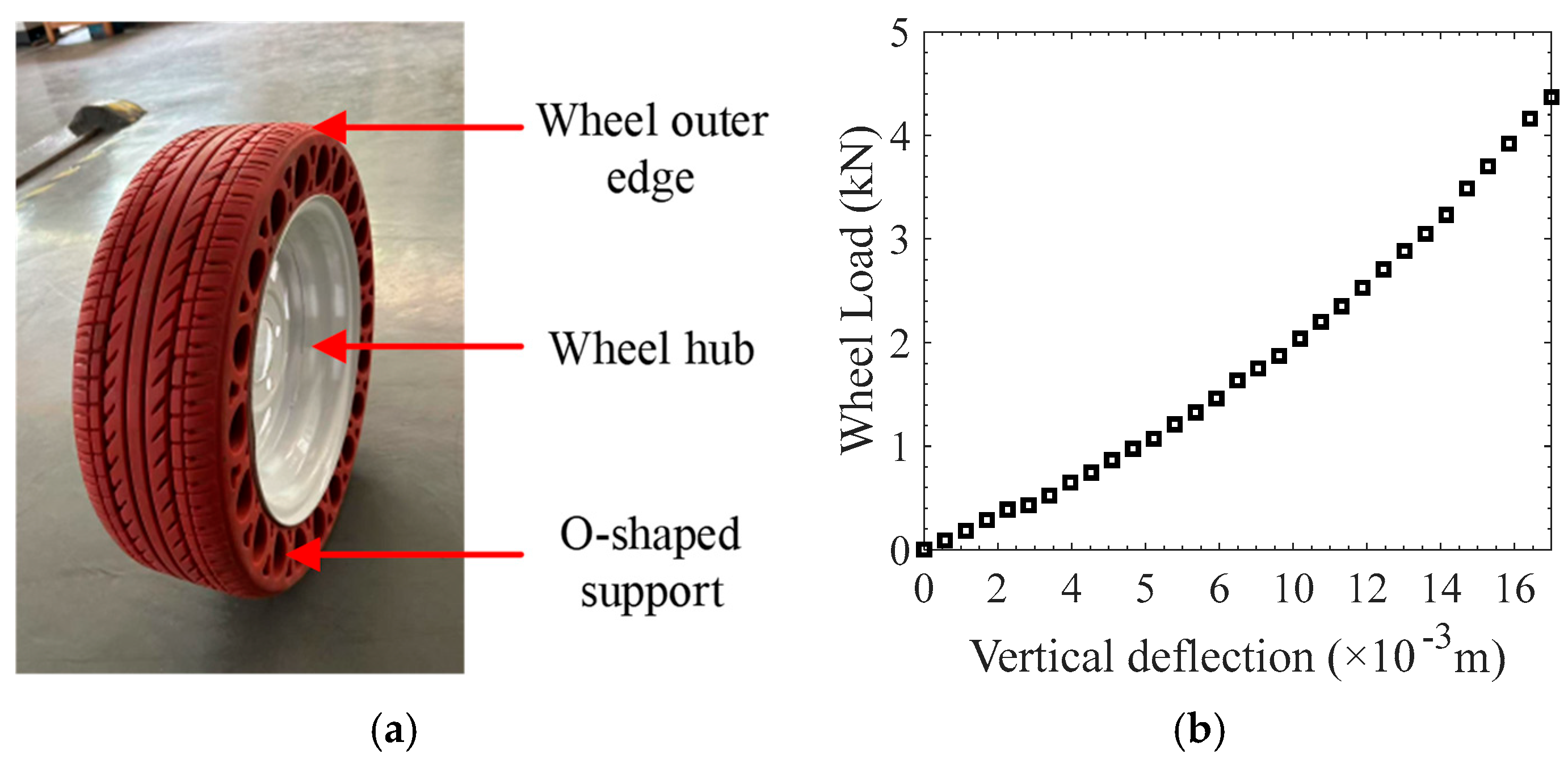
2.1. Stiffness Model of Non-Pneumatic Wheel

The non-pneumatic wheel studied in this paper is shown in Figure 1a, and has an O-support structure. In order to construct the radial stiffness model of this wheel, reference [19] obtained its mechanical properties through a static load-deflection test, and the results are shown in Figure 1b. To facilitate controller design, the literature utilizes a linear function to fit the test results. However, it is difficult for the fitted linear stiffness to accurately reflect the stiffness characteristics of the wheel. To this end, this study proposes a segmented linear fitting method based on the test data to improve the accuracy of the non-pneumatic wheel stiffness model.
The radial stiffness of the non-pneumatic wheel shown in Figure 2a can be obtained by performing first-order differentiation on the results in Figure 1b. Considering both the segmentation complexity and stiffness segmentation errors at segment points, this paper establishes a piecewise linearized model for the non-pneumatic wheel’s radial stiffness, as expressed in Equation (1).
k w x = 146.892 , 0 x < 2 176.916 , 2 x < 4 206.940 , 4 x < 6 236.964 , 6 x < 8 266.988 , 8 x < 10 297.012 , 10 x < 12 321.180 , 12 x < 13.22 342.540 , x 13.22
where k w denotes the radial stiffness of the non-pneumatic wheel in kN/mm, while x is the wheel vertical deflection in mm.
Figure 2b presents a comparison between the piecewise linearized model and the actual radial stiffness of the non-pneumatic wheel. As observed from the figure, the segmented linearization model of the wheel radial stiffness is segmented reasonably. Compared with the linear model fitted in the literature [19], the proposed model can better reflect the radial stiffness characteristics of the non-pneumatic wheel.

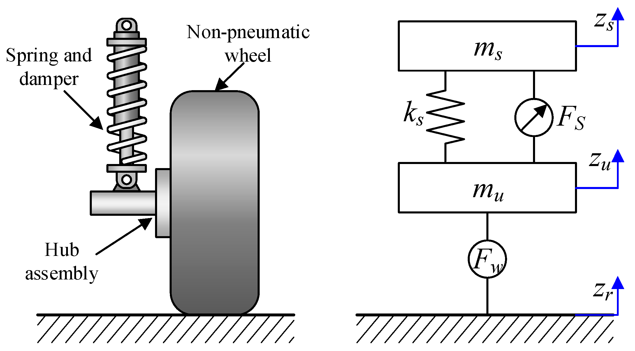
2.2. Integrated Quarter Vehicle Model

The quarter vehicle model, integrating a non-pneumatic wheel and semi-active suspension, is shown in Figure 3. The semi-active suspension is mounted between the body and the wheel to attenuate vehicle vibrations caused by road excitation.
Assuming that the position of the system when the vehicle is in static equilibrium is the initial position, the dynamic differential equations of the quarter vehicle system can be derived using Newton’s second law, as follows:
m s z ¨ s + k s ( z s z u ) + F s = 0 m u z ¨ u k s ( z s z u ) + F t F s = 0
where m s is the sprung mass, denoting the mass directly supported by the suspension system, which is mainly composed of the body shell, frame, doors, etc. m u is the unsprung mass, denoting the mass that is not supported by the suspension system, and consists mainly of the hub, rim, tire, etc. z s and z u denote the vertical displacements of the sprung mas and unsprung mass, respectively; k s denotes the spring stiffness; F s is the computed semi-active control force; and F t is the radial wheel force that overcomes the vehicle mass, which can be calculated using
F t = k w x ( m s + m u ) g
where x = δ w ( z u z r ) ; δ w is the static wheel deflection; g denotes the acceleration due to the gravity of earth; and z r denotes the input road disturbance.
As can be seen, the controller design for system (2) will be complicated due to the presence of Equation (3). In order to facilitate the controller design, the concept of wheel equivalent stiffness k e w is introduced to simplify Equation (3), where
k e w x e = 146.881 , 10.88 x e < 8.88 176.905 , 8.88 x e < 6.88 206.929 , 6.88 x e < 4.88 236.953 , 4.88 x e < 2.88 266.977 , 2.88 x e < 0.88 297.001 , 0.88 x e < 1.12 321.171 , 1.12 x e < 2.34 342.5 , 2.34 x e
Then, Equation (3) can be rewritten as
F t = k e w x e = k e w ( z u z r )
Taking the state variables as x = [ x 1 x 2 x 3 x 4 ] T , where x 1 = z s , x 2 = z ˙ s , x 3 = z u , x 4 = z ˙ u , and defining the suspension control force and road excitation as inputs, the system state equations are obtained as follows:
x ˙ 1 = x 2 x ˙ 2 = 1 m s k s ( x 1 x 3 ) + u x ˙ 3 = x 4 x ˙ 4 = 1 m u k s ( x 1 x 3 ) k e w ( z u z r ) + u

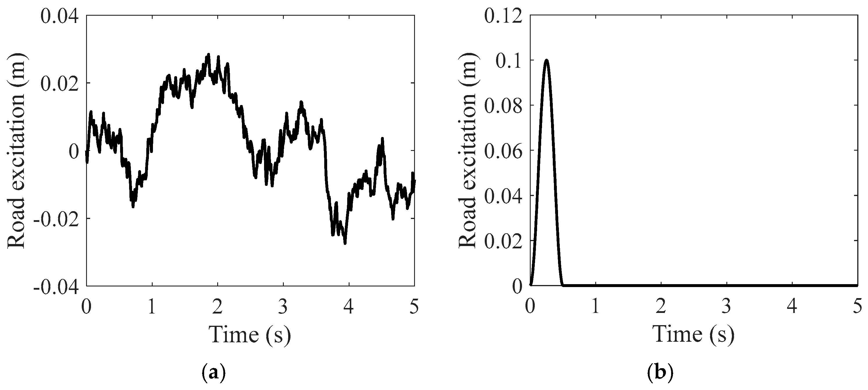
2.3. Road Excitation Model

In this study, two types of road excitations are used in order to comprehensively analyze the vibration suppression effect of the proposed control strategy on vehicles equipped with non-pneumatic wheels. Firstly, a random road excitation model is constructed to investigate the dynamic response characteristics of the vehicle under steady state road disturbances. A filtered white noise method from the existing literature [21] is employed to construct the random road excitation model, with the specific computational formulas expressed as follows:
z ˙ r ( t ) = 2 π f 0 ν z r ( t ) + 2 π n 0 G q ( n 0 ) ν w ( t )
where f 0 = 0.011 Hz denotes the lower cut-off frequency; n 0 = 0.1 m−1 is the reference spatial frequency and G q n 0 is the corresponding road PSD, which is related to the road class; w ( t ) is white noise with zero mean; and v denotes longitudinal vehicle speed.
In addition, a bumpy road excitation model is constructed in this study to investigate the effectiveness of the proposed control method under a transient impact road. According to the international standard ISO 8608 [22], the road elevation input under bumpy roads can be calculated by the following equation
z r ( t ) = A 2 1 cos 2 π v L t ,   0 t L v 0 ,   t > L v
where A and L are the height and length of the bumpy road input, respectively, which are generally taken as A = 0.1 m and L = 5 m. Here, it is assumed that the vehicle passes over the bump at a speed of 36 km/h, so we have v = 36 km/h. The Class-B road (vehicle speed of 72 km/h) and bumpy road excitation generated using Equations (7) and (8) are shown in Figure 4.

2.4. Problem Formulation

The main control objectives of this study for vehicles equipped with pneumatic-free tires can be summarized as follows:
  • To achieve effective coordination between vehicle ride comfort and handling stability, a reference model based on robust control theory is designed to provide ideal reference trajectories for sprung mass displacement and velocity;
  • The designed controller is robust and adaptable to time-varying road disturbances;
  • In order to ensure the safety of the vehicle during traveling, the system should satisfy three constraints. First, to prevent the suspension from hitting the limit blocks, the suspension working space should be kept within the maximum travel,
z s z u z max 1
where z m a x is the maximum travel of semi-active suspension.
Then, the dynamic wheel load should be less than the static wheel load to prevent the wheels from jumping off the ground, that is,
F t ( m s + m u ) g < 1
In addition, it should be ensured that the control force is within the maximum output range of the actuator:
u F max 1
where F m a x denotes the maximum force of suspension actuator.

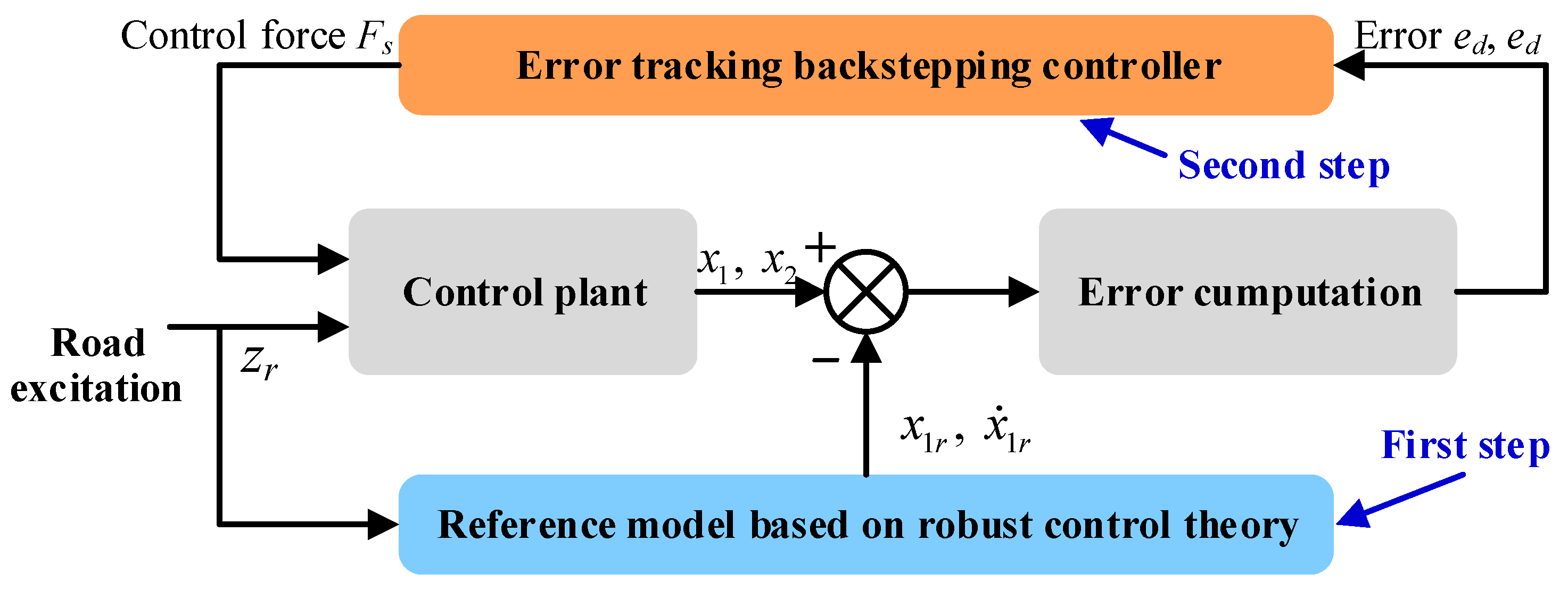
3. Reference Model-Based Backstepping Control

The architecture of the proposed reference model-based semi-active suspension backstepping control system for vehicles equipped with non-pneumatic wheels is shown in Figure 5. The controller design process is mainly divided into two steps: the first step is to design a model reference system based on the robust control theory, which aims to harmonize the contradiction between the body acceleration and the dynamic wheel load, while the second-step is to design a backstepping controller, tracking the sprung mass displacement and velocity of the model reference system, to achieve effective control of vehicle vibration.

3.1. Reference Model Design

To begin with, a reference model needs to be designed to obtain the desired sprung mass displacement and velocity. Considering the effect of system constraints and actuator saturation on the suspension control performance, a robust H controller is developed for the reference model.
Taking x r = x 1 r x 2 r x 3 r x 4 r T as the state variable of the system, where x 1 r = z r s z r u , x 2 r = z ˙ r s , x 3 = z r u z r , x 4 = z ˙ r u , then the state equation of the model reference system can be obtained as follows:
x ˙ r = A r x r ( t ) + B r u ( t ) + B r w w ( t )
where w t = z ˙ r denotes the velocity input of road, u t = F s denotes the desired control force, and
A r = 0 1 0 1 k s m s 0 0 0 0 0 0 1 k s m u 0 k e w m u 0 ,   B r = 0 1 m s 0 1 m u ,   B r w = 0 0 1 0 .
The control objective of this study is to improve vehicle ride comfort while ensuring wheel–ground contact. According to the research objectives and the constraints shown in Equations (9)–(11), the system performance outputs and constraint outputs can be defined as follows, respectively:
z = z ¨ s
z lim = z r s z r u z max k e w ( z r u z r ) ( m s + m u ) g F s F max T
The above equations can be further written in the form of the following equation of state:
z ( t ) = C r 1 x r ( t ) + D r u 1 u ( t ) z lim ( t ) = C r 2 x r ( t ) + D r u 2 u ( t )
where D r u 1 = 1 / m s , C r 1 = k s / m s 0 0 0 , and
C r 2 = 1 / z max 0 0 0 0 0 k e w / ( m s + m u ) g 0 0 0 0 0 ,   D r u 2 = 0 0 1 / F max .
Assuming that all system state quantities are measurable, the following state feedback control law can be designed:
u ( t ) = K x r ( t )
where K R 1 × 4 is the control gain to be solved.
Substituting Equation (16) into Equations (12) and (15), the state equation of the closed-loop control system is obtained as follows:
x ˙ r = ( A r + B r K ) x r ( t ) + B r w w ( t ) z ( t ) = ( C r 1 + D r u 1 K ) x r ( t ) z lim ( t ) = ( C r 2 + D r u 2 K ) x r ( t )
The above equation can be rewritten as
x ˙ r = A ¯ r x r ( t ) + B ¯ r w w ( t ) z ( t ) = C ¯ r 1 x r ( t ) z lim ( t ) = C ¯ r 2 x r ( t )
where A ¯ r = A r + B r K , B ¯ r w = B r w , C ¯ r 1 = C r 1 + D r u 1 K , C ¯ r 2 = C r 2 + D r u 2 K .
In order to obtain the desired dynamics, the designed control law should fulfill the following requirements:
  • Closed-loop system (18) asymptotic stabilization;
  • The H norm of the closed-loop system transfer function from the output z to the perturbation w ( t ) satisfies G w z ( j w ) < γ ;
  • The closed-loop system (18) satisfies the time-domain constraints (9)–(11).
The suspension control gain satisfying the above requirements can be obtained using the following theorem.
Theorem 1
([23]). For given scalars γ > 0 , ρ > 0 and system (18), if there exists a set of feasible solutions ( Q , Y ) such that the following inequality holds,
Q A r T + A r Q + B r Y + Y T B r T B r w Q C r 1 T + Y T D r u 1 T * γ 2 I 0 * * I < 0
I ρ C ¯ r 2 i Q * Q < 0 ,   i = 1 , 2 , 3
then the closed-loop system (18) is asymptotically stabilized by a given feedback control gain K and satisfies the constraints shown in Equations (9)–(11), where C ¯ r 2 i denotes the i-th element in the matrix C ¯ r 2 , and K = Y Q 1 .
The proof of Theorem 1 can be found in reference [23]. The desired H control gain can be obtained by solving the linear matrix inequalities shown in Equations (19) and (20). It is to be noted that since the nonlinear wheel stiffness is segmented and linearized in this study, it is necessary to perform control gain solving for linear systems with different stiffnesses, and thus construct a gain set containing multiple sets of control gains.

3.2. Backstepping Controller Design

The error tracking backstepping controller design is carried out in order to simplify the model reference system while considering the effect of unknown perturbations on the system performance. According to Equation (6), the control equations for the vertical motion of the sprung mass are as follows:
x ˙ 1 = x 2 x ˙ 2 = 1 m s k s ( x 1 x 3 ) + u
We can define the tracking error of the sprung mass displacement and its derivatives as
e d = x 1 r x 1 e ˙ d = x ˙ 1 r x 2
The combination of Equation (22) and Equation (21) can be rewritten as
e ˙ d = x ˙ 1 r x 2 x ˙ 2 = 1 m s k s ( x 1 x 3 ) + u
Take x 2 as the virtual control quantity and e d as the regulated variable, and define the following Lyapunov function:
V 1 = 1 2 e d 2
Take the ideal value x 2 r of x as follows:
x 2 r = x ˙ 1 r + c 1 e d
where c 1 is a positive constant.
Then, we can obtain
V ˙ 1 = e d e ˙ d = e d x ˙ 1 r x 2 r = c 1 e d 2 < 0
Furthermore, consider the error between the virtual control quantity x 2 and the ideal value x 2 r :
e v = x 2 x 2 r
Based on Equations (22) and (27), define the second Lyapunov function as follows:
V 2 = 1 2 e d 2 + 1 2 e v 2
From Equation (28), the final suspension control force is obtained as follows:
u = m s c 2 e v c 1 e ˙ v x ¨ 1 r k s x 1 x 3
where c 2 is another positive constant.
Taking the derivative of V 2 yields
V ˙ 2 = e d e ˙ d + e v e ˙ v = c 1 e d 2 + e v 1 m s k s ( x 1 x 3 ) + u x ¨ 1 r c 1 e ˙ d
After bringing Equation (29) into Equation (30), it can be found that
V ˙ 2 = c 1 e d 2 c 2 e v 2 < 0
From Equation (31), for any c 1 > 0 and c 2 > 0 , the derivative of the Lyapunov function V 2 is negative definite, and the system satisfies the Lyapunov stability condition, which ensures that the system is globally asymptotically stable.

4. Simulation Results and Discussion

In order to verify the effectiveness and superiority of the designed reference model-based backstepping control strategy (defined as controller 2), a dynamics comparison simulation is performed using the uncontrolled scheme (defined as passive suspension) and classical modified skyhook control strategy (defined as controller 1) [24] as a comparison object. In order to enhance the ride comfort and ensure wheel–ground contact, the damping coefficient of the uncontrolled scheme is determined as 1000 N·s/m [25], and the control gain of the modified skyhook control strategy is determined as ( c s k y = 1500 , c p = 500 ) using the optimization method proposed in reference [26]. The system parameters used for simulation are shown in Table 1. It is worth noting that the MR damper is used to realize the ideal control force in this study, and its dynamics characteristic can be found in reference [27]. Here, it is assumed that its response time (bandwidth) is negligible. Therefore, when z ˙ s z ˙ s z ˙ u < 0 , the suspension cannot participate in the control; only when z ˙ s z ˙ s z ˙ u 0 can the suspension output the desired control force.
For the matrix inequality solution problem shown in Theorem 1, the LMI toolbox in MATLAB 2021a can be used. The wheel stiffnesses under different wheel deflections in Equation (4) are brought into Theorem 1 for solving, respectively, and the corresponding control gains can be obtained as shown in Table 2. In the actual driving process, the control gains are selected from Table 2 based on the real-time wheel deflection, and the ideal control force calculation is carried out. Considering that the real-time wheel deflection cannot be measured directly, a state observer developed in reference [28] is adopted in this study to obtain the required wheel deflection.

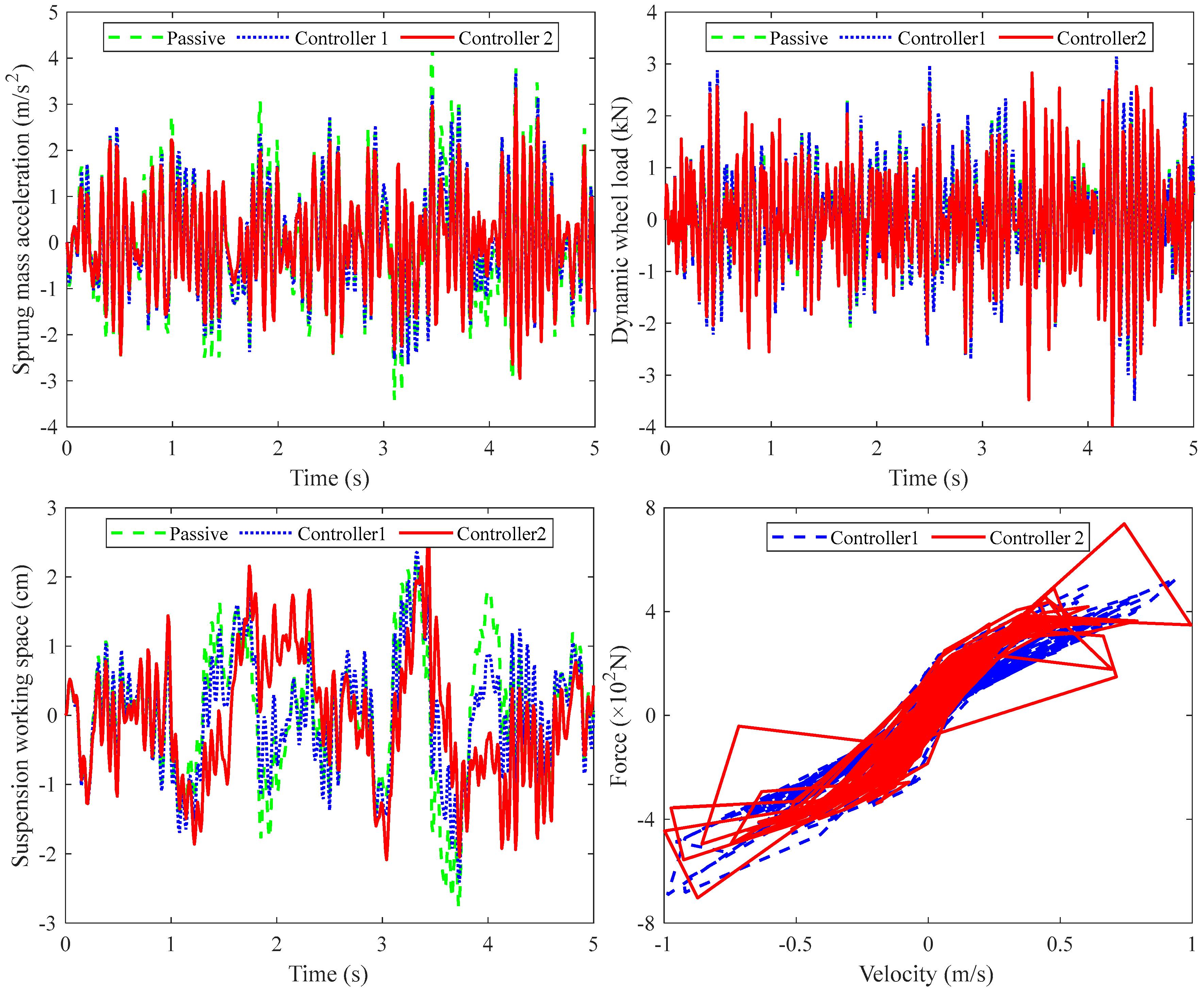
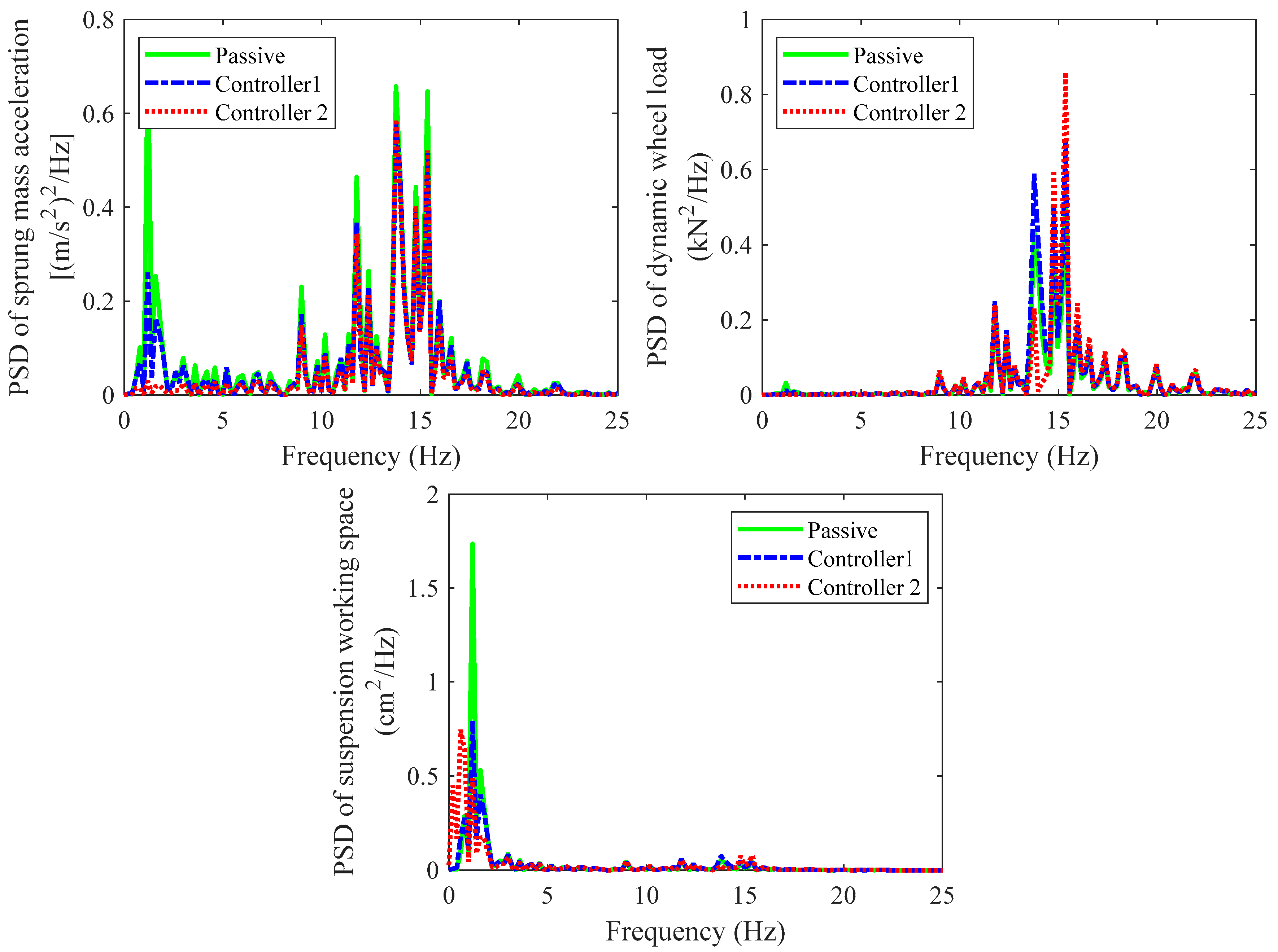
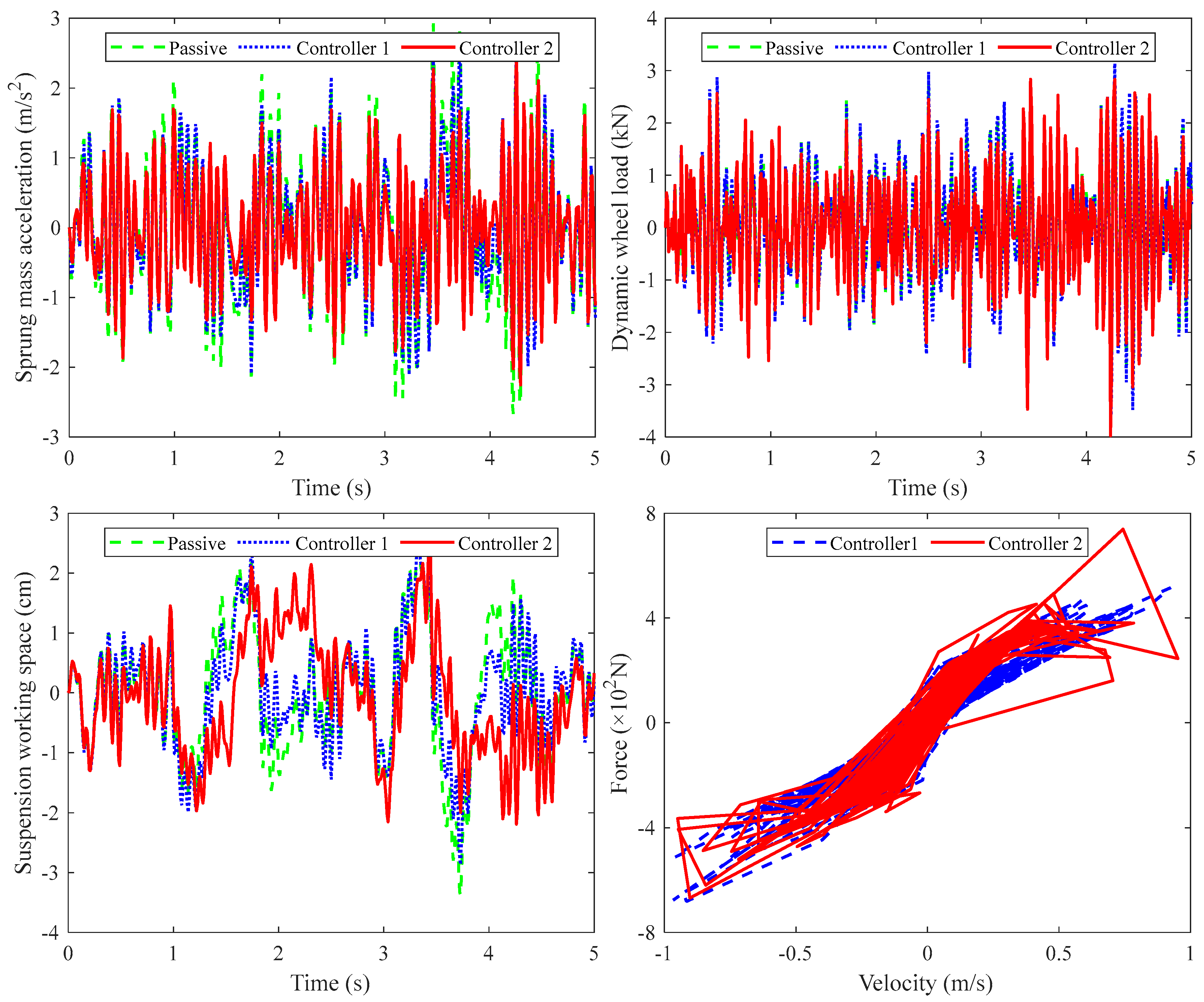
4.1. Simulation Results Under Random Road Excitation

First of all, a random road excitation is used to verify the effectiveness of the proposed control strategy. The test is conducted using the generated Class-B road shown in Figure 4a. The time-domain responses of sprung mass acceleration, suspension working space, and dynamic wheel load under random road excitation are given in Figure 6.
It can be seen from the figure that compared with the passive suspension, controller 1 can effectively reduce the sprung mass acceleration of the vehicle, but it will cause a significant increase in the dynamic wheel load. While controller 2 not only shows obviously better sprung mass acceleration than the passive suspension and controller 1, it also shows obviously better dynamic wheel load than controller 1. Additionally, it can also be found that the suspension working space under three controllers is within the maximum stroke range, that is, the vehicle safety is guaranteed. At the same time, the control force output of controllers 1 and 2 does not exceed the maximum output force of the actuator; that is, the controllers are feasible.
Based on fast Fourier transform, the corresponding frequency-domain response comparisons are given in Figure 7. It can be seen that controller 1 effectively suppresses the system response at the body resonance frequency, but degrades the PSD of the dynamic wheel load at the wheel resonance frequency. Compared with controller 1, controller 2 further improves the PSD of sprung mass acceleration at the body resonance frequency and effectively suppresses the deterioration of the PSD of the dynamic wheel load. Furthermore, the simulation results are quantitatively analyzed, and the RMS values of each system response are shown in Table 3. As shown in the table, compared with the passive suspension, controllers 1 and 2 result in a 10.5% and 20.0% reduction in the RMS of sprung mass acceleration, respectively, i.e., both enhance the ride comfort of the vehicle, but controller 2 results in a superior enhancement. Although both controllers worsened the PSD of dynamic wheel loads (by 9.0% and 4.3%, respectively), the deterioration of controller 2 is significantly smaller than that of controller 1, i.e., controller 2 can effectively ensure wheel–ground contact. The reason for the superior control effect of controller 2 is mainly due to the fact that the nonlinearity of the wheel stiffness is fully considered in the research process, a segmented linear stiffness model closer to the real stiffness characteristics is constructed, and multiple sets of control gains are designed. As a result, the designed control strategy can better cope with the variations in system parameters and external disturbances.
In fact, the sprung mass changes with the number of passengers carried by the vehicle. Therefore, in order to further verify the actual control effect of the proposed control strategy, the simulation comparison under the simulated full load condition (for example, when carrying four persons with 60 kg each, the load weight assigned to the quarter vehicle is 60 kg) is further given in Figure 8 and Table 4. It is worth noting that the variation in the sprung mass will inevitably bring about the change in the wheel load, so the simulation can simultaneously verify the effectiveness of the proposed control strategy under different payloads and varying wheel load conditions.
It can likewise be found that controller 2 obtains a sprung mass acceleration superior to that of controller 1 and the passive suspension, as well as a dynamic wheel load superior to that of controller 1. Specifically, controller 1 reduced the RMS value of the sprung mass acceleration by 9.5% compared to the passive suspension, while controller 2 reduced it by 21.2%. In addition, compared to the passive suspension, controllers 1 and 2 resulted in a 9.4% and 4.5% increase in the RMS value of the dynamic wheel loads, respectively. Controller 2 effectively suppresses the deterioration of the wheel dynamic load compared to controller 1. Combining the above results, it can be seen that the proposed control strategy also obtains a superior control effect under the full load condition, i.e., it verifies the effectiveness and generalizability of the proposed control strategy under different driving conditions.

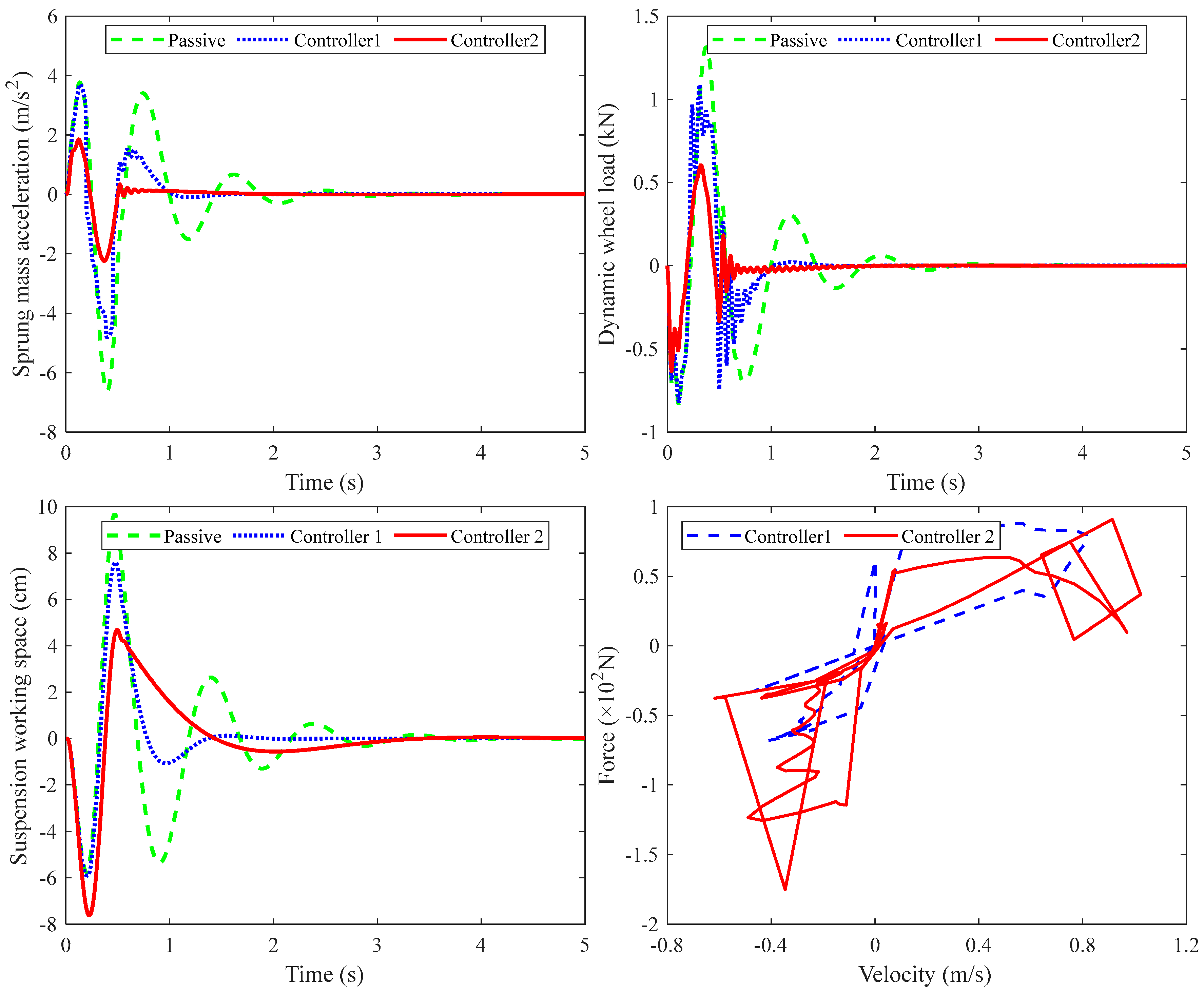
4.2. Simulation Results Under Bumpy Road Excitations

Transient bumpy roads are more likely to cause deterioration in vehicle dynamic performance than steady-state random roads. For this reason, this study further tests the control effect of the proposed control method on bumpy roads, and the obtained system time-domain response comparisons are shown in Figure 9.
Similar results were obtained under this road excitation as under the random road excitation. Controller 2 obtains a significantly lower sprung mass acceleration than the passive suspension and controller 1. It is worth noting that the dynamic wheel load obtained by controller 2 is not only lower than that of controller 1 for this road, but also lower than that of the passive suspension. In addition, controller 2 demonstrated a significant improvement in the convergence speed of all system responses, i.e., it enables the system to stabilize quickly. In other words, controller 2 obtains the optimal ride comfort and wheel–ground contact under this condition. It can also be noted that under this road excitation, the suspension working space of all three suspensions exceeds the maximum travel, i.e., the suspension will impact the limit block. However, the suspension working space obtained by controllers 1 and 2 has a significant reduction compared to the passive suspension, i.e., there is a significant reduction in the impact force. In addition, the control forces of both controllers, 1 and 2, are less than the maximum output force; that is, the system constraints are ensured.
For bumpy roads, P-P values are usually used to quantitatively evaluate the system output performance, and the P-P value comparisons of each performance index are shown in Table 5. As shown in the table, compared with passive suspension, controller 1 resulted in an 18.0% and 11.3% reduction in the P-P values of sprung mass acceleration and dynamic wheel load, respectively, which effectively improves vehicle ride comfort and wheel–ground contact. Controller 2, on the other hand, achieves significantly better vehicle dynamic performance than controller 1. Specifically, controller 2 resulted in 60.6% and 42.5% reductions in the P-P values of the sprung mass acceleration and dynamic wheel load, dramatically enhancing the ride comfort and wheel–ground contact.
Based on the above simulation results, it can be seen that the reference model-based backstepping control strategy designed for semi-active suspension in this study can effectively improve the ride comfort of vehicles equipped with non-pneumatic wheels while ensuring wheel–ground contact. Furthermore, its control performance is significantly better than the current commonly used modified skyhook control strategy.

5. Conclusions

In this study, a novel reference model-based backstepping control strategy for semi-active suspension is proposed for a quarter vehicle system equipped with non-pneumatic wheels. A segmented linearization method was used to approximate the nonlinear tire stiffness during the system modeling process. A suspension controller with robust H∞ performance was proposed based on Lyapunov stability theory, and the control gain adapted to the segmental nonlinear stiffness was designed, which greatly improved the ride comfort and wheel–ground contact performance of the vehicle. On this basis, an error tracking backstepping controller was designed using the suspension system with H∞ control as a reference. With this method, the model reference system can be simplified to reduce the difficulty of actual engineering practice and filter out the interference of system uncertain parameters. Finally, comparative simulations under random and bumpy roads were performed with the modified skyhook control as a comparison. The results indicate that the proposed control method can significantly improve the ride comfort of the vehicle while ensuring wheel–ground contact.

Author Contributions

Conceptualization, J.C. and W.L.; methodology, J.C.; validation, J.C. and D.S.; writing—original draft preparation, J.C.; writing—review and editing, W.L. and R.W.; supervision, R.D. and R.W.; funding acquisition, R.W. All authors have read and agreed to the published version of the manuscript.

Funding

This research was funded by the National Key Research and Development Program of China, grant number 2023YFB2504500, National Natural Science Foundation of China, grant number 52472410, the “Unveiling the List and Taking Command” Tackling Project of Nantong, grant number JB2022003, and the Key Laboratory of Modern Agricultural Equipment and Technology (Jiangsu University), Ministry of Education, grant number MAET202331.

Data Availability Statement

Data are contained within the article.

Conflicts of Interest

The authors declare no conflicts of interest.

Abbreviations

The following abbreviations are used in this manuscript:
RMSRoot mean square
PSDPower spectral density
P-PPeak to peak

References

  1. Chen, G.; Du, G.; Xia, J.; Xie, X.; Wang, Z. Aperiodic Sampled-Data H Control of Vehicle Active Suspension System: An Uncertain Discrete-Time Model Approach. IEEE Trans. Ind. Inf. 2024, 20, 6739–6750. [Google Scholar] [CrossRef]
  2. Wong, P.K.; Li, W.; Ma, X.; Yang, Z.; Wang, X.; Zhao, J. Adaptive Event-Triggered Dynamic Output Feedback Control for Nonlinear Active Suspension Systems Based on Interval Type-2 Fuzzy Method. Mech. Syst. Signal Process. 2024, 212, 111280. [Google Scholar] [CrossRef]
  3. Liu, Z.; Si, Y.; Sun, W. Ride Comfort Oriented Integrated Design of Preview Active Suspension Control and Longitudinal Velocity Planning. Mech. Syst. Signal Process. 2024, 208, 110992. [Google Scholar] [CrossRef]
  4. Wang, Q.; Zhao, Y.; Xu, H.; Deng, Y. Adaptive Backstepping Control with Grey Signal Predictor for Nonlinear Active Suspension System Matching Mechanical Elastic Wheel. Mech. Syst. Signal Process. 2019, 131, 97–111. [Google Scholar] [CrossRef]
  5. Zheng, Z.; Rakheja, S.; Sedaghati, R. A Comparative Study of Static and Dynamic Properties of Honeycomb Non-Pneumatic Wheels and a Pneumatic Wheel. Proc. Inst. Mech. Eng. Part D J. Automob. Eng. 2021, 235, 3631–3646. [Google Scholar] [CrossRef]
  6. Zheng, Z.; Rakheja, S.; Sedaghati, R. Cornering Stiffness Characteristics of Honeycomb Wheels: A Parametric Analysis Using Response Surface Method. Compos. Struct. 2022, 288, 115418. [Google Scholar] [CrossRef]
  7. Jin, X.; Hou, C.; Fan, X.; Sun, Y.; Lv, J.; Lu, C. Investigation on the Static and Dynamic Behaviors of Non-Pneumatic Tires with Honeycomb Spokes. Compos. Struct. 2018, 187, 27–35. [Google Scholar] [CrossRef]
  8. Liu, W.; Liu, S.; Li, X.; Zhang, Q.; Wang, C.; Li, K. Static Stiffness Properties of High Load Capacity Non-Pneumatic Tires with Different Tread Structures. Lubricants 2023, 11, 180. [Google Scholar] [CrossRef]
  9. Li, H.; Zhao, Y.; Lin, F.; Zhu, M. Nonlinear Dynamics Modeling and Rollover Control of an Off-Road Vehicle with Mechanical Elastic Wheel. J. Braz. Soc. Mech. Sci. Eng. 2018, 40, 51. [Google Scholar] [CrossRef]
  10. Li, H.; Zhou, H.; Yang, J.; Ge, J.; Wang, G.; Xu, T. Study of the Dynamic Performance of Rolling Non-Pneumatic Tires Using Finite Element Method. J. Braz. Soc. Mech. Sci. Eng. 2022, 44, 289. [Google Scholar] [CrossRef]
  11. Xiao, Z.; Zhao, Y.; Lin, F.; Zhu, M.; Deng, Y.; Zang, L. The Multi-Objective Optimization of a Non-Pneumatic Wheel Based on Its Life Prediction. Eng. Comput. 2019, 36, 997–1020. [Google Scholar] [CrossRef]
  12. Ali, I.; Rahman, M.Z.U.; Hussain, A.; Ghaffar, A.; Zafar, S. A Finite Element Analysis Based Design of a Non-Pneumatic Wheel Chair Castor. J. Eng. Res. 2025, 13, 351–360. [Google Scholar] [CrossRef]
  13. Hryciów, Z.; Jackowski, J.; Żmuda, M. The Influence of Non-Pneumatic Tyre Structure on Its Operational Properties. Int. J. Automot. Mech. Eng. 2020, 17, 8168–8178. [Google Scholar] [CrossRef]
  14. Zang, L.; Wang, X.; Yan, P.; Zhao, Z. Structural Design and Characteristics of a Non-Pneumatic Tire with Honeycomb Structure. Mech. Adv. Mater. Struct. 2022, 29, 4066–4073. [Google Scholar] [CrossRef]
  15. Zhou, H.; Li, H.; Mei, Y.; Wang, G.; Liu, C.; Zhang, L. Research on Vibration Reduction Method of Nonpneumatic Tire Spoke Based on the Mechanical Properties of Domestic Cat’s Paw Pads. Appl. Bionics Biomech. 2021, 2021, e9976488. [Google Scholar] [CrossRef]
  16. Xu, H.; Zhao, Y.; Ye, C.; Lin, F. Integrated Optimization for Mechanical Elastic Wheel and Suspension Based on an Improved Artificial Fish Swarm Algorithm. Adv. Eng. Softw. 2019, 137, 102722. [Google Scholar] [CrossRef]
  17. Zhao, Y.; Xu, H.; Deng, Y.; Wang, Q. Multi-Objective Optimization for Ride Comfort of Hydro-Pneumatic Suspension Vehicles with Mechanical Elastic Wheel. Proc. Inst. Mech. Eng. Part D J. Automob. Eng. 2019, 233, 2714–2728. [Google Scholar] [CrossRef]
  18. Ding, R.; Wang, P.; Wang, R.; Sun, D. Design and Optimization of a New Vibration Damping System for the Driving Characteristics of the Selected Case of Replacing Pneumatic Wheels with Nonpneumatic Wheels. Shock Vib. 2023, 2023, e6050633. [Google Scholar] [CrossRef]
  19. Liu, W.; Wang, R.; Rakheja, S.; Ding, R.; Meng, X.; Sun, D. Vibration Analysis and Adaptive Model Predictive Control of Active Suspension for Vehicles Equipped with Non-Pneumatic Wheels. J. Vib. Control 2023, 30, 3207–3219. [Google Scholar] [CrossRef]
  20. Jiang, Y.; Wang, R.; Ding, R.; Zhou, Y. Design and Hybrid Control of a New Self-Powered Electromagnetic Suspension Actuator Matched with Non-Pneumatic Tire. Int. J. Automot. Technol. 2023, 24, 159–169. [Google Scholar] [CrossRef]
  21. Shao, X.; Naghdy, F.; Du, H.; Qin, Y. Coupling Effect between Road Excitation and an In-Wheel Switched Reluctance Motor on Vehicle Ride Comfort and Active Suspension Control. J. Sound Vib. 2019, 443, 683–702. [Google Scholar] [CrossRef]
  22. ISO 8608; Mechanical Vibration-Road Surface Profiles-Reporting of Measured Data. ISO: Geneva, Switzerland, 1995.
  23. Guo, L.-X.; Zhang, L.-P. Robust H∞ Control of Active Vehicle Suspension under Non-Stationary Running. J. Sound Vib. 2012, 331, 5824–5837. [Google Scholar] [CrossRef]
  24. Liu, C.; Chen, L.; Lee, H.P.; Yang, Y.; Zhang, X. Generalized Skyhook-Groundhook Hybrid Strategy and Control on Vehicle Suspension. IEEE Trans. Veh. Technol. 2023, 72, 1689–1700. [Google Scholar] [CrossRef]
  25. Zhao, J.; Wang, X.; Wong, P.K.; Xie, Z.; Jia, J.; Li, W. Multi-Objective Frequency Domain-Constrained Static Output Feedback Control for Delayed Active Suspension Systems with Wheelbase Preview Information. Nonlinear Dyn. 2021, 103, 1757–1774. [Google Scholar] [CrossRef]
  26. Hong, K.-S.; Sohn, H.-C.; Hedrick, J.K. Modified Skyhook Control of Semi-Active Suspensions: A New Model, Gain Scheduling, and Hardware-in-the-Loop Tuning. J. Dyn. Syst. Meas. Control 2002, 124, 158–167. [Google Scholar] [CrossRef]
  27. Wang, R.; Sheng, F.; Ding, R.; Meng, X.; Sun, Z. Vehicle Attitude Compensation Control of Magneto-Rheological Semi-Active Suspension Based on State Observer. Proc. Inst. Mech. Eng. Part D J. Automob. Eng. 2021, 235, 3299–3313. [Google Scholar] [CrossRef]
  28. Dugard, L.; Sename, O.; Aubouet, S.; Talon, B. Full Vertical Car Observer Design Methodology for Suspension Control Applications. Control Eng. Pract. 2012, 20, 832–845. [Google Scholar] [CrossRef]
Figure 1. Mechanical properties of non-pneumatic wheel: (a) wheel structure; (b) static load-deflection test results.
Machines 13 00476 g001
Figure 2. Radial stiffness of non-pneumatic wheel: (a) test results; (b) piecewise linearized results.
Machines 13 00476 g002
Figure 3. Simplified quarter vehicle model.
Machines 13 00476 g003
Figure 4. Generated road excitations: (a) class-B road; (b) bumpy road.
Machines 13 00476 g004
Figure 5. Control scheme of proposed reference model-based backstepping controller.
Machines 13 00476 g005
Figure 6. Comparison of time-domain responses under Class-B road excitation.
Machines 13 00476 g006
Figure 7. Comparison of frequency-domain response under Class-B road excitation.
Machines 13 00476 g007
Figure 8. Comparison of time-domain response under Class-B road excitation with full load.
Machines 13 00476 g008
Figure 9. Comparison of time-domain response under bumpy road excitation.
Machines 13 00476 g009
Table 1. System parameters used in simulation.
DescriptionUnitValue
Sprung mass ( m s )kg201
Unsprung mass ( m u ) kg38.8
Spring Stiffness ( k s )N/m11,413
Acceleration due to gravity ( g )m/s29.81
Maximum suspension travel ( z m a x )m0.06
Maximum output force ( F m a x )N3000
Table 2. Control gains under different wheel deflections.
Wheel Deflection (×10−3 m)Control Gain
10.88 x e < 8.88 K 1 = 10,375 ,   680.6 ,   16,139 ,   1029.9
8.88 x e < 6.88 K 2 = 10,375 ,   670.5 ,   13,706.2 ,   947.5
6.88 x e < 4.88 K 3 = 10,375 ,   664.3 ,   11,897.6 ,   881.4
4.88 x e < 2.88 K 4 = 10,375 ,   660.1 ,   10,501.8 ,   827.1
2.88 x e < 0.88 K 5 = 10,375 ,   657.2 ,   9393.2 ,   781.4
0.88 x e < 1.12 K 6 = 10,375 ,   655.1 ,   8491.6 ,   742.5
1.12 x e < 2.34 K 7 = 10,375 ,   653.8 ,   7879.4 ,   714.9
2.34 x e K 8 = 10,375 ,   652.9 ,   7406 ,   693
Table 3. Comparison of RMS values of sprung mass acceleration and dynamic wheel load.
Control SchemeRMS of Sprung Mass AccelerationRMS of Dynamic Wheel Load
Value (m/s2)ImprovementValue (kN)Improvement
Passive1.327/1.042/
Controller 11.18810.5%1.136−9.0%
Controller 21.06120.0%1.087−4.3%
Table 4. Comparison of RMS values under full load conditions.
Control SchemeRMS of Sprung Mass AccelerationRMS of Dynamic Wheel Load
Value (m/s2)ImprovementValue (kN)Improvement
Passive1.038/1.041/
Controller 10.9399.5%1.139−9.4%
Controller 20.81821.2%1.088−4.5%
Table 5. Comparison of RMS values under bumpy road excitation.
Control SchemeP-P Value of the Sprung Mass Acceleration (m/s2)P-P Value of the Dynamic Wheel Load (kN)
ValueImprovementValueImprovement
Passive10.392/2.155/
Controller 18.51718.0%1.91111.3%
Controller 24.09260.6%1.23942.5%
Disclaimer/Publisher’s Note: The statements, opinions and data contained in all publications are solely those of the individual author(s) and contributor(s) and not of MDPI and/or the editor(s). MDPI and/or the editor(s) disclaim responsibility for any injury to people or property resulting from any ideas, methods, instructions or products referred to in the content.

