Abstract
Micro-hole aerostatic bearings have emerged as critical components in ultra-precision machining systems, offering a superior load capacity, stiffness, and stability compared to traditional orifice-based designs. These enhancements are primarily attributed to the high-density configurations of micro-holes and the reduction in hole diameter. However, research on the design and analysis of micro-hole aerostatic bearings for high-rotational-speed applications remains limited. In this study, the finite element method (FEM) was employed to solve the Reynolds equation, thereby conducting a systematic evaluation of the static and high-speed performance characteristics of micro-hole aerostatic thrust bearings. The effects of restrictor types, micro-hole layouts, structural parameters, and centrifugal deformation under high-rotational-speed conditions on bearing performance have been comprehensively examined. The objective of this study is to provide a basis for the design of micro-hole high-speed aerostatic spindles.
1. Introduction
High-speed, high-performance electric spindles are essential components in modern machining systems [1]. Aerostatic bearings, which utilize a compressible air film for non-contact support, offer distinct advantages such as a high speed, high rotational precision, low vibration, excellent thermal stability, and long service life [2,3]. Currently, aerostatic bearing restrictors are classified into four main types: orifice restrictors, porous restrictors, annular restrictors, and slot restrictors. Among these, orifice restrictors have been widely adopted in industry, primarily due to their superior load capacity, high stiffness, and ease of manufacturing [4].
Recent breakthroughs in laser beam machining and micro-drilling technologies have enabled the fabrication of micron-scale orifices with sub-100 μm diameters [5]. This technological advancement has significantly expanded the practical design applications of micro-hole aerostatic bearings. Comparative analyses have identified two principal advantages of micro-hole restrictors over traditional orifice restrictors. Firstly, micro-hole aerostatic bearings exhibit superior load capacity and stiffness characteristics compared to traditional designs. Miyatake et al. [6] conducted numerical investigations on aerostatic thrust bearings incorporating micro-holes with diameters below 50 μm. Their results demonstrated an inverse correlation between micro-hole diameter and maximum achievable stiffness. Fan et al. [7] used microelectromechanical systems (MEMSs) to process a multiple-micro-hole air bearing and subsequently conducted experimental research. Their results demonstrated that a decrease in micro-hole diameter and an increase in micro-hole density lead to a significant reduction in pressure drop at the restrictor outlets and a more uniform pressure distribution. Belforte et al. [8] conducted experimental research on the static performance of aerostatic thrust bearings with micro-holes sub-100 μm in diameter. Their results indicated that load capacity and stiffness can be optimized by adjusting the number and diameter of micro-holes. Fan et al. [9] developed a novel methodology for the design and parametric optimization of micro-hole aerostatic bearings specifically tailored for vacuum environment applications. Their results showed a significant enhancement in both the load capacity and mass flow rate of aerostatic bearings under vacuum conditions compared to conventional atmospheric pressure environments. Through parametric analysis, the researchers identified an optimal configuration that maximizes bearing performance: specifically, a micro-hole diameter of 0.1 mm, an array of 36 micro-holes, and a distribution diameter of 38.83 mm. Lu et al. [10] conducted an investigation into the influence of micro-hole restrictor parameters on the load capacity and stiffness characteristics of aerostatic bearings. Their results revealed that an increase in micro-hole density and a decrease in micro-hole diameter lead to a progressive improvement in optimal bearing stiffness under conditions of constant throttle orifice area.
Secondly, micro-hole restrictors can enhance the stability of aerostatic bearings. Yu et al. [11] indicated that an increased number of micro-holes effectively suppresses turbulent vortices and mitigates micro-vibration phenomena. Furthermore, Li et al. [12] revealed that the damping coefficient decreases with an increase in orifice diameter within specific parametric ranges. Studies have established that aerostatic bearings are susceptible to pneumatic hammer vibration when the gas volume effect predominates over the squeeze film damping effect [13]. Notably, micro-hole restrictors maintain inherent stability advantages by avoiding any additional gas volume entering the system. Consequently, the implementation of micro-hole restrictors effectively eliminates the risk of pneumatic hammer vibration, thereby significantly enhancing the operational stability of aerostatic bearings.
Furthermore, the behavior of aerostatic bearings at ultra-high speed differs significantly from their performance under static conditions. Huang et al. [14] developed a mathematical model for hybrid herringbone-grooved journal bearings, incorporating the factor of shaft centrifugal expansion effects. Their research demonstrated that the implementation of herringbone groove configurations significantly enhances the load capacity of an aerostatic bearing under high-speed operations. The centrifugal expansion deformation of the shaft leads to a consequential reduction in air film thickness, which may approach the magnitude of the bearing clearance under high-speed operations. Therefore, it is important to consider the centrifugal expansion effect in the rotor dynamics calculations.
In the field of aerostatic bearings’ performance analysis, three methodologies are predominantly employed: the Reynolds equation [15,16], computational fluid dynamics (CFD) [17,18,19], and experimental approaches [20,21]. Among these, the Reynolds equation is generally applicable for describing the flow of viscous compressible gases in small gaps. This study employs the finite element method to numerically solve the Reynolds equation, facilitating a comprehensive comparative analysis of the performance characteristics between micro-hole and orifice restrictors. Furthermore, this study systematically examines the influence of micro-hole arrangement patterns and geometric parameters on bearing performance across various operational scenarios. Additionally, this study incorporates an analysis of centrifugal effects on the shaft during high-speed operations and their consequent impact on bearing performance. In previous studies, most of the research has concentrated on micro-hole aerostatic bearings operating under static conditions. In contrast, this study specifically targets micro-hole high-speed double-sided aerostatic thrust bearings. Moreover, current research on centrifugal effects predominantly focuses on journal bearings, whereas the structural deformation characteristics of thrust bearings under high-speed conditions are often overlooked. This study, therefore, aims to fill this gap by focusing on thrust bearings.
2. Bearing Structures
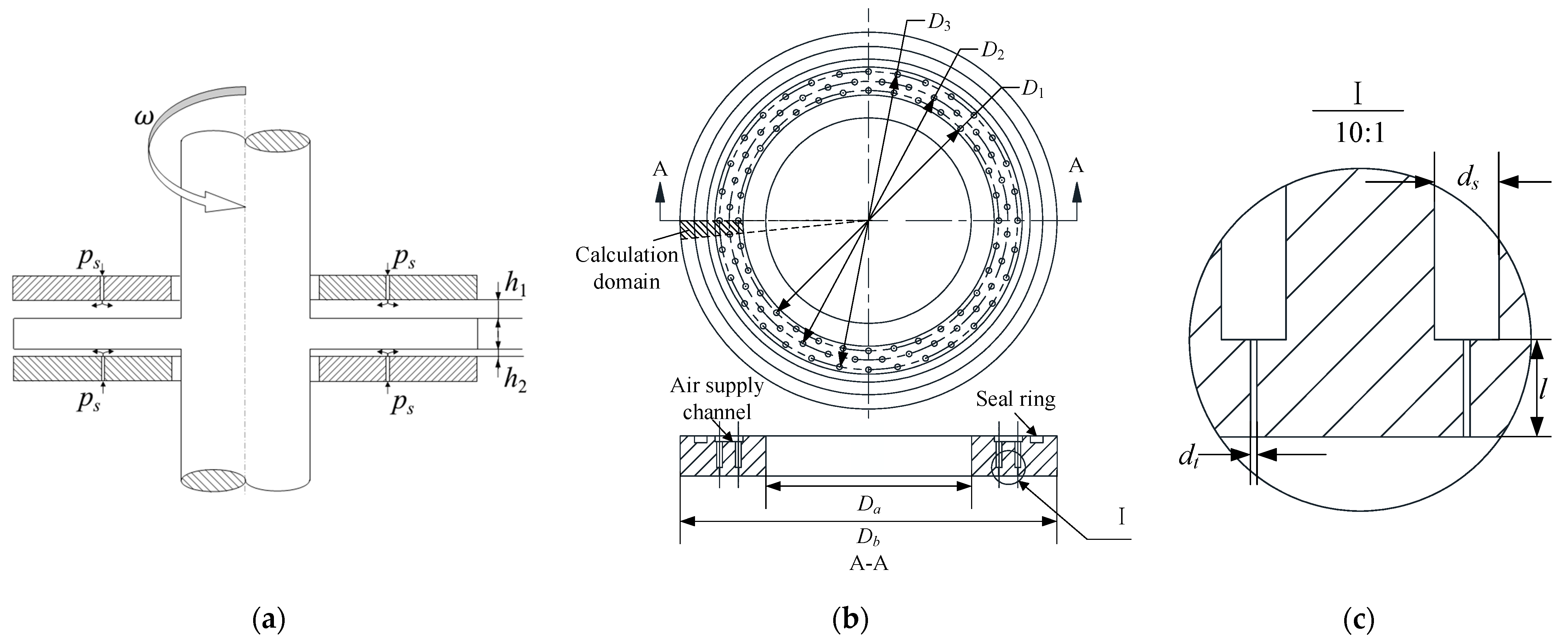
The operational principle of aerostatic thrust bearings is based on the formation of a compressible air film within the bearing clearance. When externally pressurized gas is introduced through precisely engineered restrictors, a hydrodynamic lubrication film is established within the bearing clearance, which generates both load capacity and stiffness. In the initial equilibrium state, the annular thrust disc maintains a symmetrical air film thickness on both surfaces, resulting in a uniform pressure distribution across the bearing surfaces. Under these conditions, the bearing exhibits a negligible load capacity. However, during operational conditions, the external force induces variations in the thickness of the air film, resulting in load capacity. The three-row micro-hole aerostatic thrust bearing, as illustrated in Figure 1, features a specific geometric configuration with 32 circumferentially distributed micro-holes. The intermediate row of micro-holes is arranged in a staggered pattern to enhance pressure distribution uniformity across the bearing’s surface. The structural parameters of the bearing are as in Table 1.
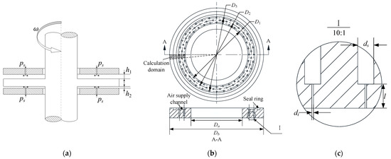
Figure 1.
Structural design of the aerostatic thrust bearing. (a) Schematic of double-sided aerostatic thrust bearing; (b) micro-hole layout of three-row thrust bearing; (c) local enlargement of micro-holes.

Table 1.
Structural parameters of the bearing.
3. Modeling
3.1. Governing Equation
Before establishing the computational model, the following assumptions were made:
(1) Since the bearing employs forced water cooling, the gas flow field in the bearing is considered isothermal, and thermal deformation of the structure is neglected.
(2) The gas viscosity is insensitive to gas pressure and temperature, and the gas viscosity coefficient is assumed to be constant.
(3) The dimension in the direction of the air film thickness is three orders of magnitude smaller than the length and width of the bearing. Therefore, it can be assumed that the pressure in the flow field remains constant in the direction of the air film thickness.
The Reynolds equation is generally applicable for describing the flow of viscous compressible gases in small gaps [22]. The derivation of the Reynolds equation is achieved by integrating the continuity equation, the momentum equation, and the ideal gas state equation. The pressure distribution across the thrust bearing’s surfaces can be quantitatively determined by solving the Reynolds equation under appropriate boundary conditions. The Reynolds equation in polar coordinates can be expressed in the following form:
where p represents the pressure of the air film; r and θ represent the radial, angular in the polar coordinate system; ρ represents gas density; h represents the air film thickness; represents the gas velocity at the restrictor outlet; = 1 and = 0 represent the existence and nonexistence of restrictors; η represents the kinematic viscosity coefficient of the gas; pa represents the atmospheric pressure; ρa represents atmospheric density. Take rb, ps, and hm as the reference values, and obtain the normalized values as follows:
where rb represents the radius of the aerostatic bearing; ps represents the supply pressure; hm represents the reference value of air film thickness; represents the gas mass flow factor of the restrictor; , , and represent the normalized values of r, p, and h, respectively. The dimensionless form of the Reynolds equation can be obtained by combining Equation (1) with Equation (2).
The dimensionless form of the Reynolds equation is degraded using the Galerkin weighted residual method:
where δf denotes the variant of f treated by the variational method.
The simplification process reduces the partial differential equation’s order, from a second-order to a first-order formulation. This reduction in order alters the continuity requirements for the solution function, necessitating only first-order continuity rather than the more stringent second-order continuity. Consequently, this transformation substantially simplifies the construction of interpolation functions during the discretization process and enhances computational efficiency.
Generally, the mass flow rate of air through an orifice is developed as an ideal nozzle. The pressure is reduced from ps to pd through the orifice. The ideal mass flow rate is derived as
where dt is the orifice diameter; pd is the downstream pressure; κ is the ratio of the specific heat and equals 1.4 for air.
However, the actual mass flow rate differs from that of an ideal nozzle, so the mass flow rate needs to be corrected by employing discharge coefficients [23].
The load capacity W, stiffness KW, and volume flow rate Q of aerostatic bearings can be obtained from the following calculation method:
The Reynolds number (Re) is a crucial parameter in determining the flow state of gas within the air film clearance of a high-speed aerostatic thrust bearing:
where μ is dynamic viscosity. It has been determined that at a rotational speed of 60,000 r/min and an air film thickness of 10 µm, the maximum Re is 115.83. This value is significantly lower than the critical value of 2000. Consequently, the flow state within the air film clearance can be classified as laminar flow.
3.2. Meshing
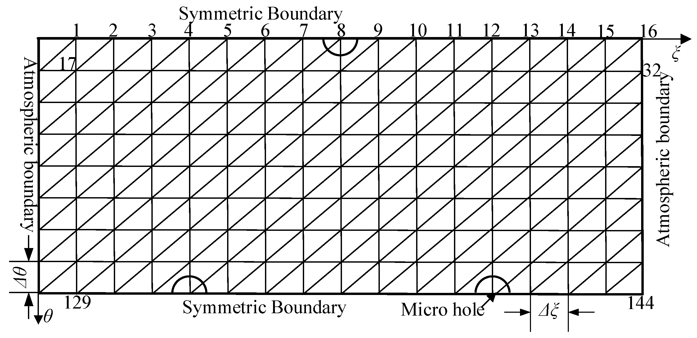
The FEM model of the aerostatic thrust bearing is illustrated in Figure 2. The computational domain is discretized into nθ segments along the circumferential direction and nξ elements along the radial direction. Recognizing the significant impact of mesh density on numerical accuracy, an evaluation of the aerostatic thrust bearing’s static performance was conducted across multiple mesh configurations, with the results documented in Table 2. All simulations were performed under a constant gas supply pressure of 0.5 MPa. As shown in Table 1, the relative differences in load capacity, stiffness, and volume flow rate between the two mesh configurations were maintained below 0.2%, which demonstrated good numerical convergence [24]. As a result, Mesh 1 was selected for this investigation, achieving an optimal balance between computational accuracy and resource efficiency.
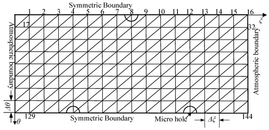
Figure 2.
Computational domain.
Table 2.
Mesh-independent analysis.
3.3. Experimental Validation
To validate the accuracy and reliability of the numerical model, a comprehensive comparison was conducted between the simulation results and experimental data obtained from the referenced study [16]. The comparative analysis focused on two critical performance parameters, load capacity and stiffness, across three distinct bearing configurations, as presented in Table 3. Table 4 provides a detailed quantitative comparison of the load capacity and stiffness values obtained from both experimental measurements and numerical simulations for these three bearing configurations. The comparative analysis reveals that most of the relative deviations between experimental and simulated values remain within a 10% margin, which validates the accuracy and reliability of the computational model employed in this investigation.
Table 3.
Bearing parameters for experimental verification [16].
Table 4.
Results of load capacity and stiffness according to experiment and numerical analysis.
4. Results and Discussions
4.1. Static Performance
4.1.1. Performance Comparisons Between Orifice and Micro-Hole
To systematically assess the performance advantages of micro-hole restrictors over conventional orifice restrictors, a comparative study was conducted involving two distinct types of restrictors. The structural parameters of the aerostatic thrust bearings utilized in this investigation are shown in Table 5. Bearing IV employs conventional orifice restrictors, each with a diameter of 0.2 mm, uniformly distributed in an array of eight orifices along the circumferential direction. In contrast, Bearing V employs micro-hole restrictors with a reduced diameter of 0.1 mm, arranged in a denser configuration of thirty-two micro-holes distributed circumferentially. This specific geometric configuration ensures that both restrictor types possess identical total cross-sectional flow areas, thereby maintaining equivalent flow resistance characteristics while varying the restrictor geometry. The air film thickness is set at 10 µm, with a gas supply pressure of 0.6 MPa and an outlet pressure equivalent to ambient pressure, ensuring consistent boundary conditions for both configurations.
Table 5.
Structure parameters of the aerostatic thrust bearings.
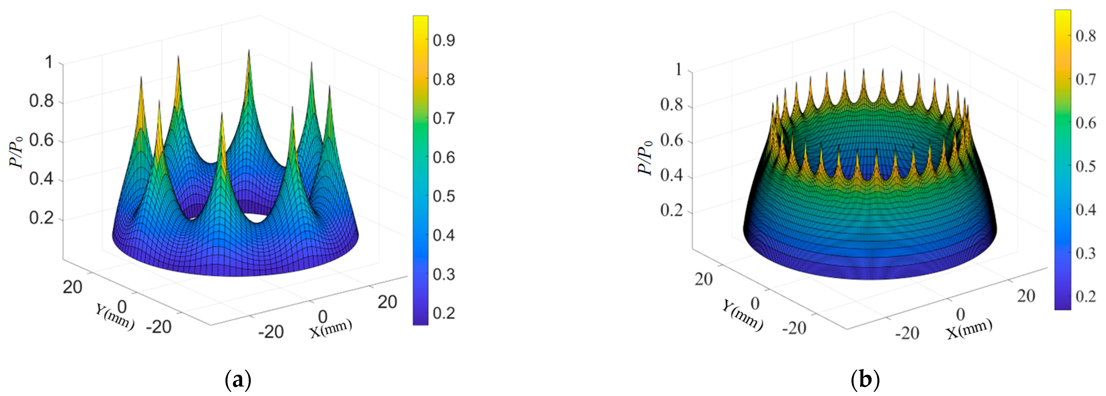
Figure 3 presents the dimensionless pressure distributions for Bearing IV and Bearing V. As the compressed gas flows through the restrictors, a pressure drop is experienced. The gas subsequently expands through the air film region, with its pressure gradually decreasing to ambient conditions at the outlet. To facilitate a comprehensive comparative analysis of pressure variations, the pressure curves along both the radial and circumferential directions were extracted and visualized in two-dimensional representations, as shown in the Figure 4. The results reveal that the pd associated with the micro-hole restrictor is lower than that of the orifice restrictor. In the radial direction, both types of restrictors exhibit a pressure drop from the restrictor towards the gas outlet. Bearing V demonstrates a convex pressure distribution curve with a more gradual pressure decay. In contrast, Bearing IV maintains a concave pressure distribution throughout the radial direction. Bearing V shows better uniformity in circumferential pressure distribution than Bearing IV, due to its higher restrictor density. This enhanced pressure uniformity, coupled with a higher mean pressure level, explains the observed improvement in the load capacity of micro-hole restrictors compared to orifice restrictors.

Figure 3.
Dimensionless pressure distributions for Bearing IV and Bearing V. (a) Bearing IV; (b) Bearing V.
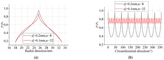
Figure 4.
Dimensionless pressure distributions for Bearing IV and Bearing V in the radial and circumferential directions. (a) Radial direction; (b) circumferential direction.
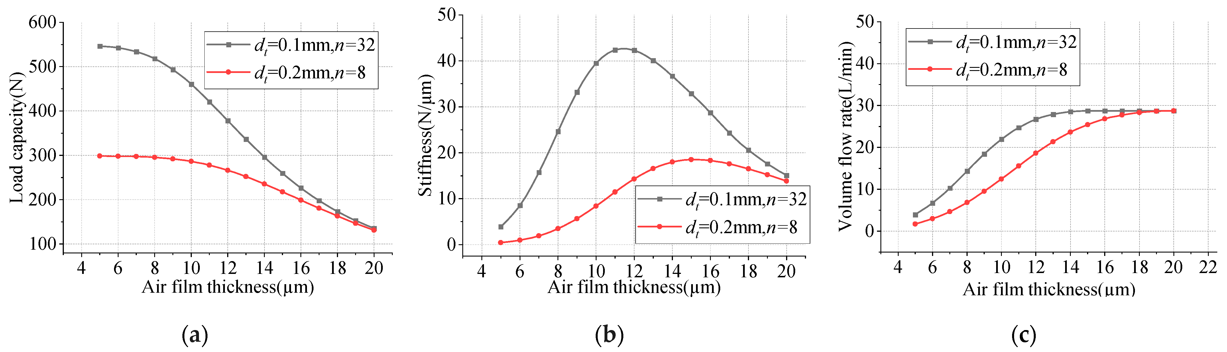
As illustrated in Figure 5, the load capacity of both Bearing IV and Bearing V decreases with an increasing air film thickness. The stiffness demonstrates a non-monotonic behavior, initially increasing to a maximum value before subsequently decreasing as the air film thickness increases. Within the investigated range of a 5 to 20 µm air film thickness, Bearing V consistently demonstrates superior load capacity and stiffness characteristics compared to Bearing IV. Notably, at an air film thickness of 20 µm, the performance metrics of both restrictor types converge to equivalent values. The optimal stiffness condition occurs at a distinct air film thickness for each configuration, 15 µm for Bearing IV and 11 µm for Bearing V, indicating a 27% reduction in optimal air film thickness for Bearing V. The maximum stiffness of Bearing V is more than twice that of Bearing IV. Additionally, the volume flow rate of both orifice and micro-hole aerostatic thrust bearings increases with an increasing air film thickness. For Bearing V, the volume flow rate stabilizes at about 14 µm, whereas for Bearing IV, it stabilizes at 19 µm, with an equal volume flow rate at the stable value.
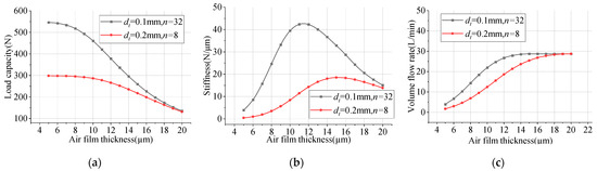
Figure 5.
Results of load capacity, stiffness, and volume flow rate by different restrictors. (a) Load capacity; (b) stiffness; (c) volume flow rate.
4.1.2. Micro-Hole Layouts
To further enhance the performance of the bearing, a detailed analysis of the characteristics of multi-row restrictor bearings was conducted. The intermediate row of micro-holes is arranged in a staggered pattern to enhance pressure distribution uniformity across the bearing surface. The air film thickness is set at 10 µm, with a gas supply pressure of 0.6 MPa and an outlet pressure equivalent to ambient pressure.
Figure 6 and Figure 7 present the three-dimensional and two-dimensional pressure distributions of the multi-row micro-hole aerostatic thrust bearing, respectively. Figure 7 reveals that the pd rises with the increasing number of micro-hole rows, but the rate of increase diminishes progressively. Furthermore, the average pressure becomes significantly higher, and the uniformity of the pressure distribution improves. This phenomenon suggests that while the addition of micro-hole rows enhances the pressure distribution characteristics, the improvements yield diminishing returns as the number of rows increases.

Figure 6.
Dimensionless pressure distributions by different micro-hole rows. (a) Two rows; (b) three rows.
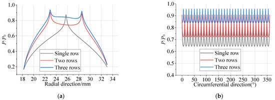
Figure 7.
Dimensionless pressure distributions by different micro-hole rows in the radial and circumferential direction. (a) Radial direction; (b) circumferential direction.
During the flow process, the gas experiences a pressure drop, resulting in a relatively stable downstream pressure. Subsequently, the gas expands through the air film region, with its pressure gradually decreasing until it reaches ambient conditions at the outlet. In close-spaced micro-hole aerostatic bearings, the pressure distribution along the bearing’s circumferential direction is relatively uniform, permitting the neglect of circumferential gas flow. The restrictor exerts an impedance effect on the fluid, and a relationship analogous to Ohm’s law governs the interplay between flow rate, pressure drop, and impedance:
where q is mass flow rate, Rex is restrictor impedance, Rf is gas film impedance, ps is gas supply pressure, pa is ambient pressure, pd is downstream pressure, Kg is gauge pressure ratio.
By constructing an impedance model of the bearing system, as depicted in Figure 8, the variation in gas pressure within the bearing clearance is simplified into a configuration analogous to electrical impedance, arranged in either series or parallel forms. This approach establishes a theoretical model that supports the design and optimization of the restrictors.
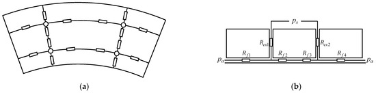
Figure 8.
Pneumatic resistance model. (a) Gas-impedance distribution of air film; (b) gas-impedance distribution in micro-hole restrictors.
The impedance formula for the multi-row micro-hole is expressed as follows [25]:
where is the pressure drop at the restrictor outlets, n is the number of restrictors, R is the restrictor diameter, and l is the length of the restrictor.
The impedance of the restrictor is directly proportional to the length of the restrictor and inversely proportional to the fourth power of the restrictor radius and the number of restrictors. Specifically, an increase in the restrictor length results in a corresponding increase in restrictor impedance, whereas an increase in the restrictor radius leads to a significant reduction in restrictor impedance. This relationship underscores the influence of geometric parameters on the impedance characteristics of the restrictor.
The impedance formula for the air film is expressed as follows [25]:
where R1 is the inner or outer diameter of the bearing, R2 is the diameter of the circumference where the micro-hole is located, h is the air film thickness.
According to the theory of pneumatic resistance, reducing the air film thickness, increasing the orifice diameter, and increasing the number of hole rows collectively result in an increase in pd. Specifically, with an increase in the density of micro-hole distribution, Rex gradually approaches zero. Consequently, pd converges toward the supply pressure instead of continuing to increase. It can be inferred that while increasing the orifice diameter and the number of rows can enhance the load capacity to some extent, it is highly likely to reduce the stiffness.
Figure 9 shows that the load capacity uniformly increases with the number of restrictor rows at a larger air film thickness. In contrast, the enhancement in load capacity diminishes as the number of restrictor rows increases at a smaller air film thickness. Furthermore, the results reveal a significant correlation between the number of restrictor rows and bearing stiffness characteristics. As shown in Figure 9b, the peak stiffness position shifts toward a greater air film thickness with increasing numbers of restrictor rows. The results demonstrate that two-row configurations achieve 5.05% higher maximum stiffness values than three-row configurations, while both outperform single-row designs. At a smaller air film thickness, the stiffness follows the following order: two-row > single-row > three-row configurations. Conversely, under conditions of a larger air film thickness, the order is three-row > two-row > single-row configurations. It is evident that beyond a certain threshold, augmenting the number of restrictor rows not only fails to further enhance the load capacity but also reduces bearing stiffness at smaller air film thicknesses. Therefore, it can be deduced that the performance of the bearing does not always improve with an increase in the number of restrictor rows; rather, the number of rows should be determined rationally based on operating conditions.
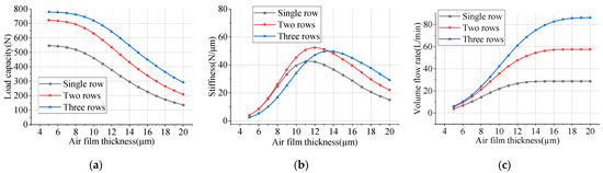
Figure 9.
Effect of micro-hole rows on bearing’s performance. (a) Load capacity; (b) stiffness; (c) volume flow rate.
4.1.3. Parametric Study
- (1)
- Diameter of micro-hole
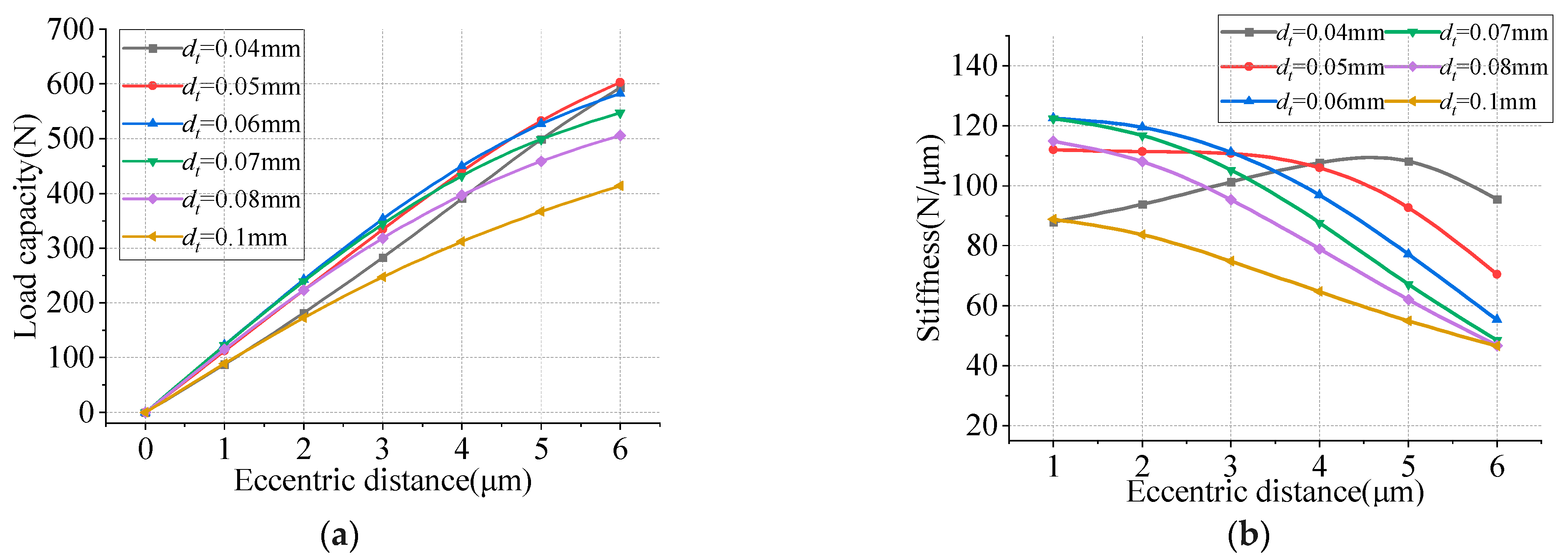
The design and analysis of bearing performance depend on several key parameters, including the geometric configuration of restrictors, micro-hole diameter, and air film thickness. In this study, double-sided bearing configurations were employed throughout the numerical analysis to simulate practical operational conditions. Figure 10 depicts the characteristics of load capacity and stiffness for a three-row double-sided thrust bearing with an air film thickness of 10 µm. The results indicate that the load capacity increases as the eccentricity rises. Within the micro-hole diameter range of 0.05 to 0.1 mm, load capacity exhibits an inverse relationship with diameter size. However, a notable deviation from this trend is observed at 0.04 mm, where the load capacity decreases below that of the 0.05 mm configuration. This suggests the presence of an optimal diameter. Regarding bearing stiffness, the data reveal a complex relationship with both micro-hole diameter and eccentricity. Within the micro-hole diameter range of 0.05 to 0.1 mm, the stiffness rises as the micro-hole diameter increases, while it diminishes with greater eccentricity. Specifically, at a 0.05 mm diameter, the stiffness remains relatively stable under low eccentricity conditions, whereas at a 0.04 mm diameter, the stiffness initially increases before decreasing with a higher eccentricity. According to the previous pneumatic resistance theory, further reducing the diameter of the micro-hole will increase the resistance of the gas as it traverses the restrictors. Consequently, the effective flow rate of the restrictors will drop. The air film cannot be fully established, which will reduce the load capacity of the bearing. Through a study of parameters and performance evaluation, the 0.05 mm micro-hole diameter configuration emerges as the optimal design parameter, offering the best balance between load capacity and stiffness characteristics across the operational range.
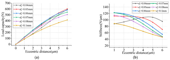
Figure 10.
Effect of micro-hole diameter on bearing performance. (a) Load capacity; (b) stiffness.
- (2)
- Air film thickness
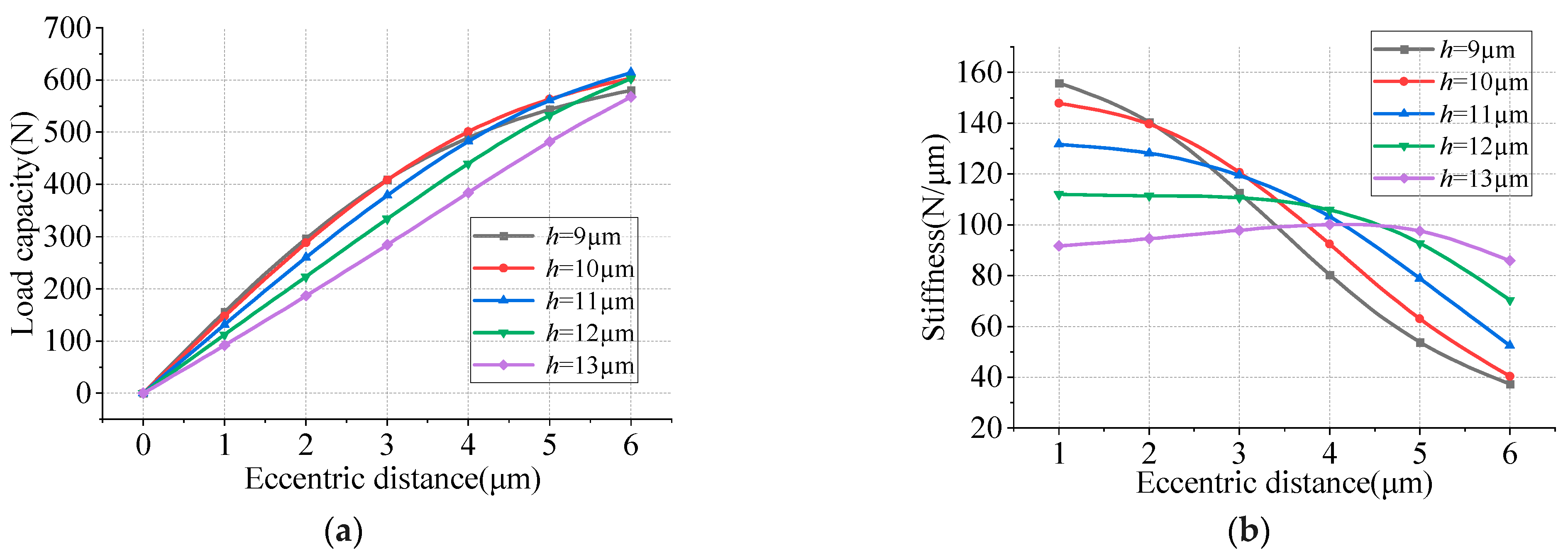
Figure 11 depicts the variation curves of load capacity and stiffness for a three-row double-sided thrust bearing with a micro-hole diameter of 0.05 mm. Within the range of air film thickness from 10 to 13 µm, the load capacity is observed to decrease gradually with increasing air film thickness. Conversely, when the air film thickness is below 10 µm, the load capacity exhibits a progressive reduction as the air film thickness decreases. The stiffness increases proportionally with eccentricity at air film thicknesses below 13 µm. At an air film thickness of 13 µm, the stiffness initially rises and then declines with increasing eccentricity. A comprehensive analysis suggests that the bearing achieves optimal performance at an air film thickness of 10 µm.
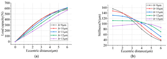
Figure 11.
Effect of air film thickness on bearing performance. (a) Load capacity; (b) stiffness.
4.2. High-Speed Performance
4.2.1. Centrifugal Effect
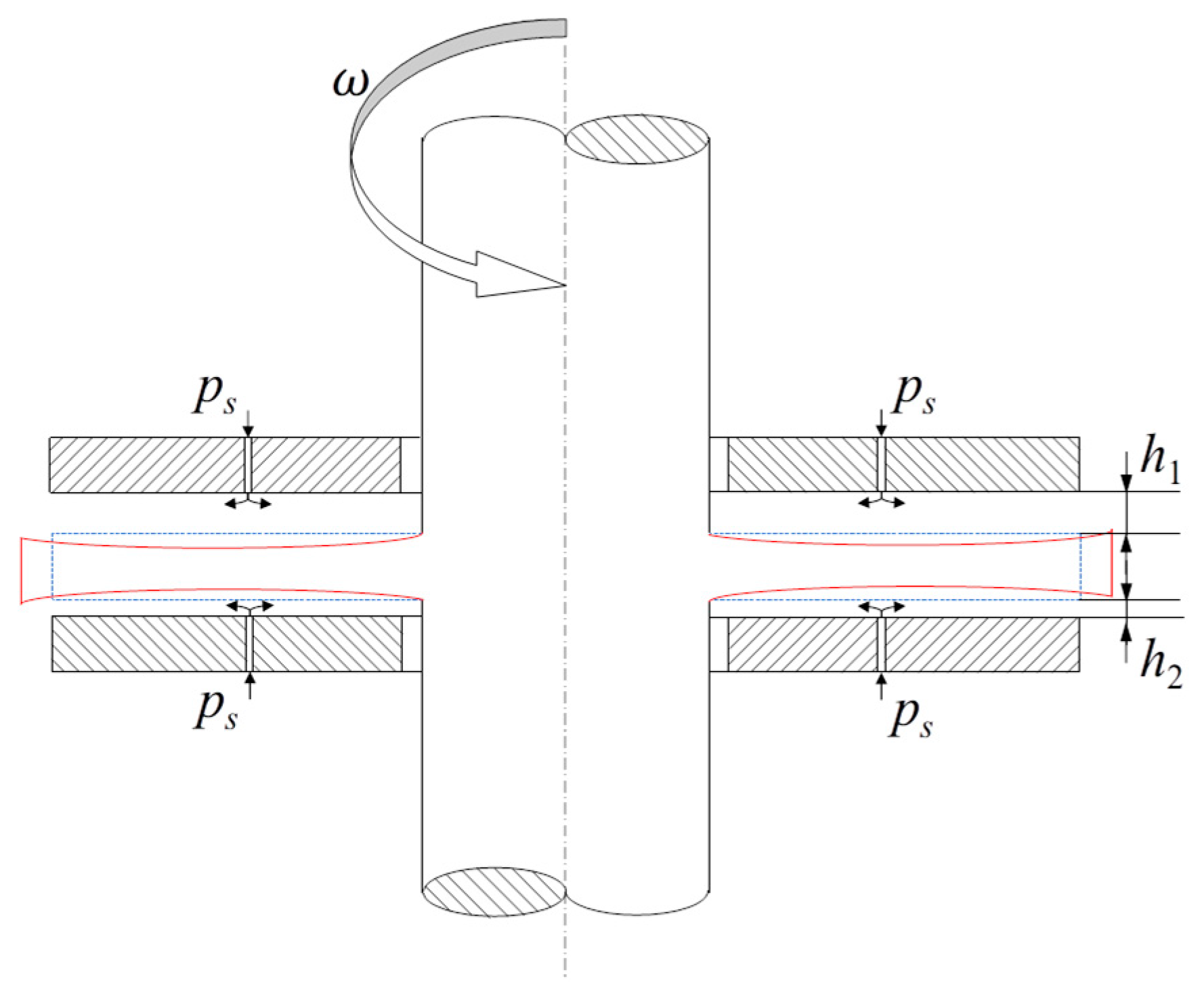
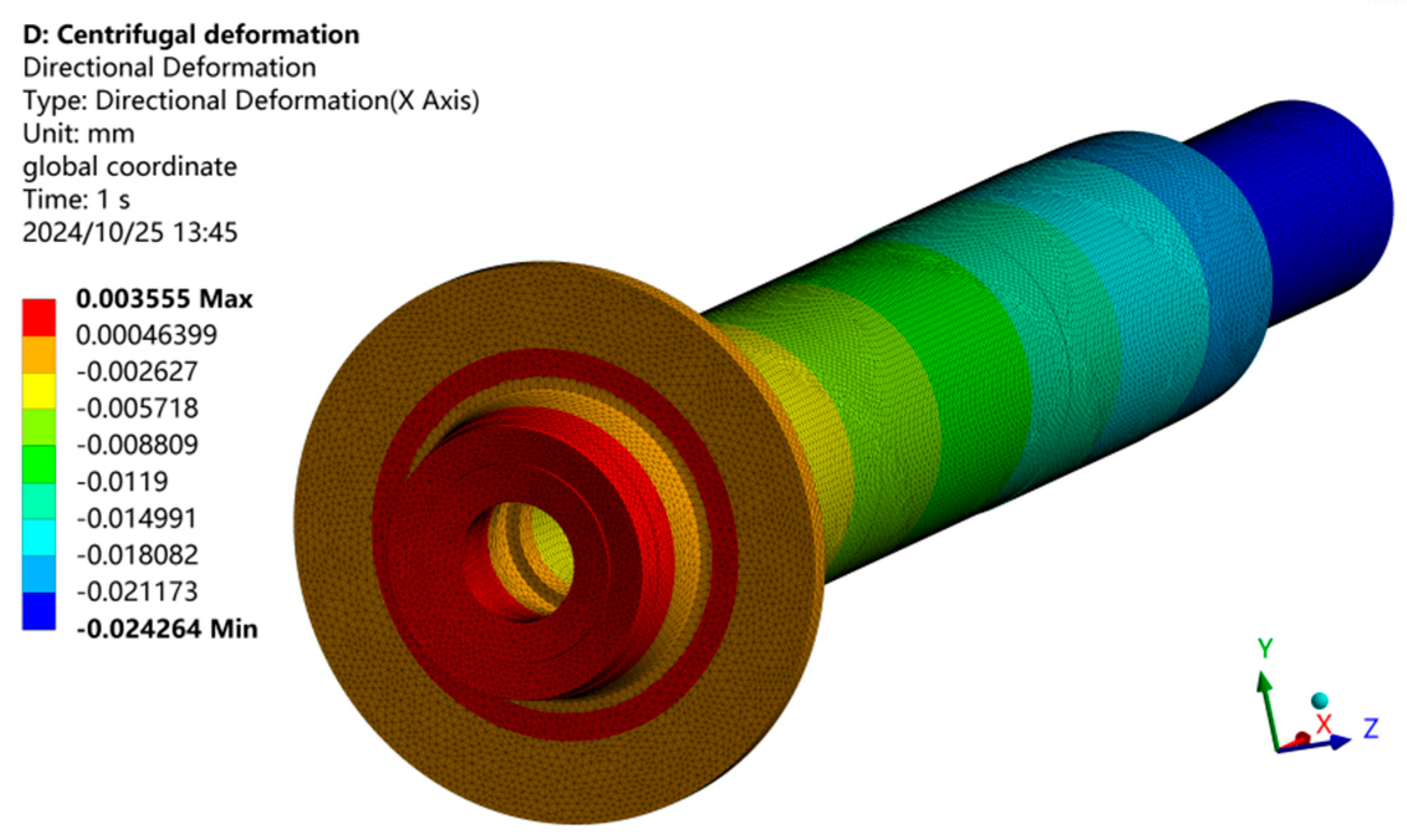
In high-speed aerostatic bearing systems, centrifugal forces significantly alter the air film thickness, consequently influencing the bearing’s operational performance. Therefore, incorporating centrifugal effects is crucial for accurately evaluating the performance of high-speed bearings. While current research predominantly focuses on journal bearings, the structural deformation characteristics of thrust bearings under high-speed conditions are often overlooked. Figure 12 illustrates the deformation profile of the thrust disk during high-speed operation, where centrifugal forces induce a concave deformation pattern. Figure 13 presents the axial deformation characteristics of the shaft at 60,000 r/min, as determined through finite element analysis (FEA). The shaft material was set as 38CrMoAl. The reference point for zero deformation was established at the center of the thrust disk. High-speed operation causes the shaft to experience axial compression towards the thrust disk, resulting in three distinct phenomena: axial shortening of the shaft, a reduction in the disk’s thickness, and a corresponding increase in air film thickness. Figure 14 demonstrates the deformation characteristics of the thrust disk by displaying the maximum, average, and minimum deformation curves. These curves reveal a quadratic relationship between shaft deformation and rotational speed. Specifically, the maximum deformation of the thrust disk reaches 2.33 µm at 130,000 r/min. To enhance computational efficiency in analytical modeling, the average deformation value was employed as a parameter to represent the variation in air film thickness. The variation in the air film thickness obtained was then imported into the FEM model for calculation.
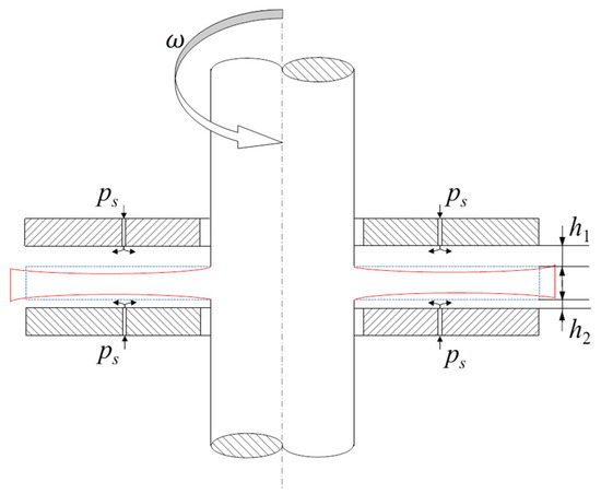
Figure 12.
Schematic diagram of centrifugal deformation of thrust bearing.

Figure 13.
Axial centrifugal deformation nephogram.
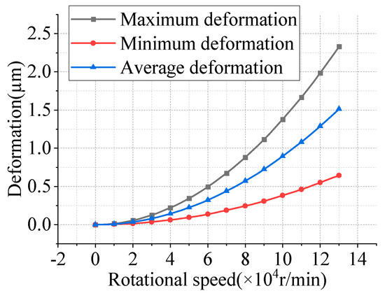
Figure 14.
Axial centrifugal deformation.
4.2.2. Performance Comparisons Under Various Rotational Speeds
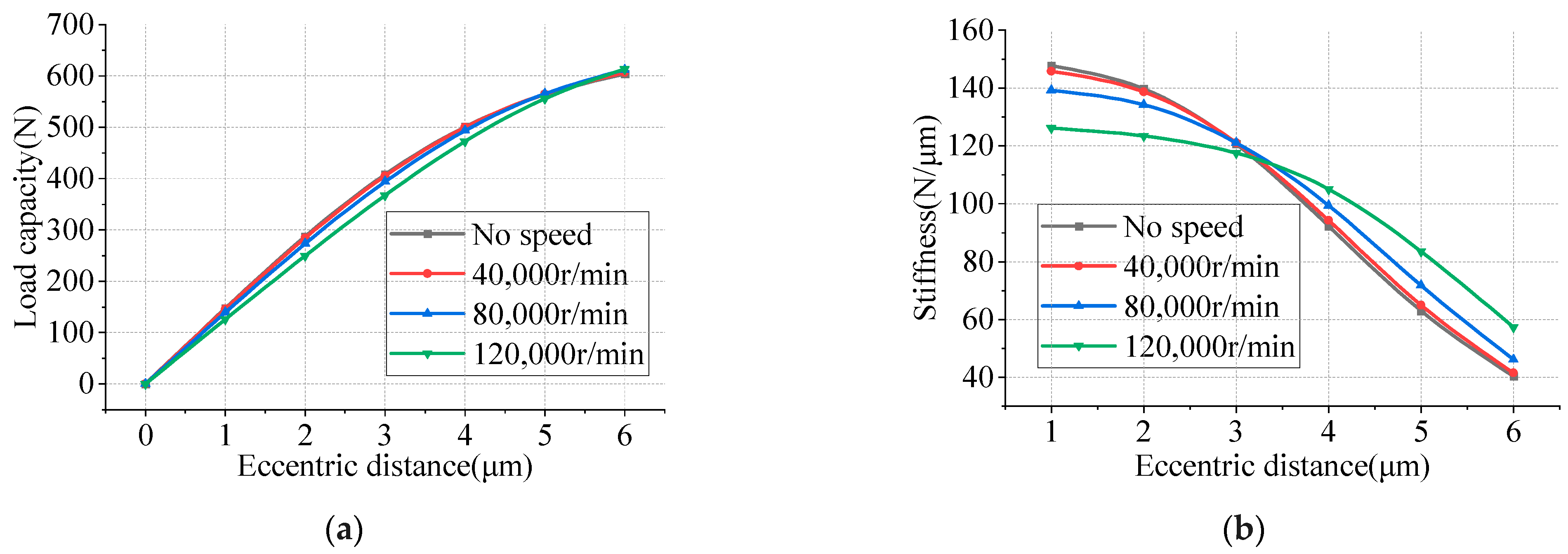
Figure 15 presents the load capacity and stiffness variation curves for a three-row double-sided thrust bearing with an air film thickness of 10 µm and a micro-hole diameter of 0.05 mm at different rotational speeds. The results showed a consistent decrease in load capacity with an increasing rotational speed. In terms of stiffness behavior, a distinct transition is observed at an eccentricity of 3 µm: (1) For eccentricities below 3 µm, the stiffness progressively declines with an increasing rotational speed. Specifically, when the eccentricity is 1 µm, the bearing stiffness is reduced by 14.28% due to the centrifugal expansion caused by a rotational speed of 120,000 r/min. (2) Conversely, when the eccentricity exceeds 3 µm, the stiffness positively correlates with the rotational speed. To summarize, the centrifugal effect induces a reduction in bearing stiffness at low eccentricities while causing an augmentation in stiffness at high eccentricities.
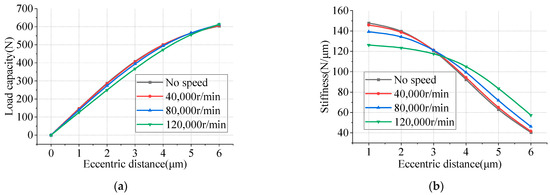
Figure 15.
Performance of aerostatic thrust bearing at different rotational speeds. (a) Load capacity; (b) stiffness.
5. Conclusions
In this investigation, the Reynolds equation was numerically solved utilizing the finite element method. The computational models were validated by comparing the results with experimental data obtained from the reference literature, thereby ensuring the accuracy and reliability of the numerical simulations. The principal findings of this study can be summarized as follows:
- (1)
- A comparative analysis was conducted to evaluate the performance of orifice and micro-hole configurations, while maintaining an identical total cross-sectional restricting area. The results demonstrated that the micro-hole configuration exhibits significantly enhanced load-bearing characteristics compared to the conventional orifice design. Specifically, the maximum stiffness of the micro-hole configuration is more than twice that of the orifice configuration.
- (2)
- The influence of the number of restrictor rows on the bearing’s performance was investigated based on the pneumatic resistance theory. The results indicated that the optimal comprehensive support performance of the bearing is achieved with two rows of micro-holes. When the number of micro-hole rows exceeds two, the increase in the bearing’s load capacity is constrained, and a reduction in bearing stiffness is observed.
- (3)
- A parametric investigation was conducted to evaluate the influence of micro-hole diameter and air film thickness on the load-bearing characteristics of thrust bearings. Extensive numerical simulations and performance analyses were employed to identify the optimal configuration. It was found that the bearing exhibits a peak operational performance when the air film thickness is set at 10 µm and the micro-hole diameter is 0.05 mm. This combination of parameters represents the most effective configuration for maximizing the load capacity and stiffness of the thrust bearing.
- (4)
- The deformation characteristics of the shaft under high-speed operating conditions were examined. Subsequently, an analysis of the effects of centrifugal force on the thrust bearing’s performance was conducted based on the acquired deformation data. It was found that the thrust disc exhibits progressive thinning with increasing rotational speed, and the magnitude of deformation follows a quadratic relationship with rotational speed. When the initial air film thickness is 10 µm, the load capacity of the bearing decreases with an increasing rotational speed. Additionally, the centrifugal effect induces a reduction in bearing stiffness at low eccentricities while causing an augmentation in stiffness at high eccentricities.
The above conclusions provide a theoretical basis for the design of micro-hole high-speed aerostatic thrust bearings, enabling their better application in high-speed aerostatic motorized spindles.
Author Contributions
Conceptualization, S.G.; methodology, S.G. and T.J.; finite element analysis software, T.J.; finite element method, H.Y. and T.J.; investigation, T.J. and Z.L.; aerostatic bearing structural design, H.Z.; resources, S.G.; data curation, T.J.; writing—original draft preparation, T.J. and Z.L.; writing—review and editing, L.S.; visualization, T.J.; supervision, Q.G. and Y.S.; project administration, M.Z. and L.L.; funding acquisition, L.L. and H.Z. All authors have read and agreed to the published version of the manuscript.
Funding
This research was funded by the National Key Research and Development Program of China, grant number 2022YFB3402705; the National Special Project of China, grant number 2023ZY01077; the Key Research and Development Program of Heilongjiang Province, grant number 2022ZX03A05; the Chongqing Natural Science Foundation, grant number CSTB2024NSCQ-MSX0820; and the Manufacturing Science and Technology Innovation Talent Project of Harbin, grant number 2023CXRCGD028.
Data Availability Statement
The data that support the findings of this study are available from the corresponding author.
Conflicts of Interest
Author Hanqian Zhang is employed by Guangzhou Haozhi Industrial Co., Ltd. The authors declare that the research was conducted without any commercial or financial relationships that could be construed as a potential conflict of interest.
References
- Abele, E.; Altintas, Y.; Brecher, C. Machine tool spindle units. CIRP Ann. Manuf. Technol. 2010, 59, 781–802. [Google Scholar] [CrossRef]
- Gao, Q.; Chen, W.; Lu, L.; Huo, D.; Cheng, K. Aerostatic bearings design and analysis with the application to precision engineering: State-of-the-art and future perspectives. Tribol. Int. 2019, 135, 1–17. [Google Scholar] [CrossRef]
- Chen, D.; Huo, C.; Cui, X.; Pan, R.; Fan, J.; An, C. Investigation the gas film in micro scale induced error on the performance of the aerostatic spindle in ultra-precision machining. Mech. Syst. Signal Process. 2018, 105, 488–501. [Google Scholar] [CrossRef]
- Wang, Y. Gas Lubrication Theory and Gas Bearing Design; China Machine Press: Beijing, China, 1999; p. 146. [Google Scholar]
- Zhao, Q.; Qiang, M.; Hou, Y.; Chen, S.; Lai, T. Research Developments of Aerostatic Thrust Bearings: A Review. Appl. Sci. 2022, 12, 11887. [Google Scholar] [CrossRef]
- Miyatake, M.; Yoshimoto, S. Numerical investigation of static and dynamic characteristics of aerostatic thrust bearings with small feed holes. Tribol. Int. 2010, 43, 1353–1359. [Google Scholar] [CrossRef]
- Fan, K.C.; Ho, C.C.; Mou, J.I. Development of a multiple-microhole aerostatic air bearing system. J. Micromech. Microeng. 2002, 12, 636–643. [Google Scholar] [CrossRef]
- Belforte, G.; Colombo, F.; Raparelli, T.; Trivella, A.; Viktorov, V. Experimental Analysis of Air Pads with Micro Holes. Tribol. Trans. 2013, 56, 169–177. [Google Scholar] [CrossRef]
- Fan, G.; Li, Y.; Li, Y.; Zang, L.; Zhao, M.; Li, Z.; Yu, H.; Xu, J.; Liang, H.; Zhang, G.; et al. Research on Design and Optimization of Micro-Hole Aerostatic Bearing in Vacuum Environment. Lubricants 2024, 12, 224. [Google Scholar] [CrossRef]
- Lu, Z.; Zhang, J.; Liu, B. Research and Analysis of the Static Characteristics of Aerostatic Bearings with a Multihole Integrated Restrictor. Shock. Vib. 2020, 2020, 7426928. [Google Scholar] [CrossRef]
- Yu, P.; Lu, J.; Luo, Q.; Li, G.; Yin, X. Optimization Design of Aerostatic Bearings with Square Micro-Hole Arrayed Restrictor for the Improvement of Stability: Theoretical Predictions and Experimental Measurements. Lubricants 2022, 10, 295. [Google Scholar] [CrossRef]
- Li, Y.; Huang, W.; Sang, R. Analysis of the Influencing Factors of Aerostatic Bearings on Pneumatic Hammering. Lubricants 2024, 12, 395. [Google Scholar] [CrossRef]
- Powell, J.W. Design of Aerostatic Bearings; Machinery Publishing: Brighton, UK, 1970. [Google Scholar]
- Huang, X.; Lin, S.; Liang, J. Modelling approach of hybrid air herringbone grooved journal bearing considering the angular misalignment and centrifugal expansion. Tribol. Int. 2023, 189, 108928. [Google Scholar] [CrossRef]
- Zheng, Y.; Yang, G.; Cui, H.; Hou, Y. Pneumatic stability analysis of single-pad aerostatic thrust bearing with pocketed orifice. Proc. Inst. Mech. Eng. Part J J. Eng. Tribol. 2020, 234, 1857–1866. [Google Scholar] [CrossRef]
- Wu, Y.; Li, C.; Li, J.; Du, J. Lubrication mechanism and characteristics of aerostatic bearing with close-spaced micro holes. Tribol. Int. 2024, 192, 109278. [Google Scholar] [CrossRef]
- Li, W.; Wang, G.; Feng, K.; Zhang, Y.; Wang, P. CFD-based investigation and experimental study on the performances of novel back-flow channel aerostatic bearings. Tribol. Int. 2022, 165, 107319. [Google Scholar] [CrossRef]
- Gao, S.; Cheng, K.; Chen, S.; Ding, H.; Fu, H. CFD based investigation on influence of orifice chamber shapes for the design of aerostatic thrust bearings at ultra-high speed spindles. Tribol. Int. 2015, 92, 211–221. [Google Scholar] [CrossRef]
- Liu, L.; Lu, L.; Yu, K.; Gao, Q.; Zhao, H.; Chen, W. A steady modeling method to study the effect of fluid-structure interaction on the thrust stiffness of an aerostatic spindle. Eng. Appl. Comput. Fluid Mech. 2022, 16, 453–468. [Google Scholar] [CrossRef]
- Wang, P.; Zhang, Y.; Feng, L.; Hou, W.; Wang, J.; Li, W.; Feng, K. Study on the pneumatic hammer phenomenon of aerostatic bearings based on the empirical mode method: Numerical and experimental analysis. Tribol. Int. 2023, 181, 108305. [Google Scholar] [CrossRef]
- Feng, K.; Wang, P.; Zhang, Y.; Hou, W.; Li, W.; Wang, J.; Cui, H. Novel 3-D printed aerostatic bearings for the improvement of stability: Theoretical predictions and experimental measurements. Tribol. Int. 2021, 163, 107149. [Google Scholar] [CrossRef]
- Liu, T.; Liu, Y.; Chen, S. Aerostatic Lubrication; Harbin Institute of Technology Press: Harbin, China, 1990. [Google Scholar]
- Song, L.; Cheng, K.; Ding, H.; Chen, S. Analysis on discharge coefficients in FEM modeling of hybrid air journal bearings and experimental validation. Tribol. Int. 2018, 119, 549–558. [Google Scholar] [CrossRef]
- Gao, S.; Shi, Y.; Xu, L.; Chen, H.; Cheng, K. Investigation on influences of herringbone grooves for the aerostatic journal bearings applied to ultra-high-speed spindles. Proc. Inst. Mech. Eng. Part C J. Mech. Eng. Sci. 2019, 233, 5795–5812. [Google Scholar] [CrossRef]
- Cheng, Y.; Li, D.; Hu, J.; Li, J. Theoretical study and experimental verification on calculation of bearing capacity of aerostatic restrictor system with a gas-impedance model. Proc. SPIE 2015, 565–575. [Google Scholar]


Disclaimer/Publisher’s Note: The statements, opinions and data contained in all publications are solely those of the individual author(s) and contributor(s) and not of MDPI and/or the editor(s). MDPI and/or the editor(s) disclaim responsibility for any injury to people or property resulting from any ideas, methods, instructions or products referred to in the content. |
© 2025 by the authors. Licensee MDPI, Basel, Switzerland. This article is an open access article distributed under the terms and conditions of the Creative Commons Attribution (CC BY) license (https://creativecommons.org/licenses/by/4.0/).