Article

Influence of Hybridization Ratio on Field Back-EMF Ripple in Switched Flux Hybrid Excitation Machines

1
School of Automation, Beijing Institute of Technology, Beijing 100081, China
2
Tangshan Research Institute, Beijing Institute of Technology, Tangshan 063000, China
*
Author to whom correspondence should be addressed.
Machines 2025, 13(6), 473; https://doi.org/10.3390/machines13060473
Submission received: 22 March 2025 / Revised: 25 May 2025 / Accepted: 29 May 2025 / Published: 30 May 2025

Abstract

:
Hybrid excited machines are strong competitors for application in hybrid/full electric vehicles due to their high torque density and strong air gap field-regulating capability. Similar to armature back-EMF, back-EMF also exists in the field windings of hybrid excited machines. However, the existence of field back-EMF is harmful to the safe and stable operation of machine systems, e.g., lower efficiency, higher torque ripple, reduced control performance, etc. In this paper, the influence of the hybridization ratio k, i.e., the ratio of the field winding slot area to the total field slot area, on the field back-EMF in hybrid excited machines with a switched flux stator is comprehensively investigated. In addition, a comparative study of the field back-EMF ripple in hybrid excited machines and wound field synchronous machines is conducted. It shows that the field back-EMF in flux-enhancing, zero field current, and flux-weakening modes is significantly affected by the hybridization ratio under different conditions. Moreover, the on-load field back-EMF in wound field machines is considerably higher than that in hybrid excited machines due to the mitigated magnetic saturation level in the field winding’s magnetic flux path. Finally, to validate the results predicted using the finite element method, a prototype hybrid excited machine is built and tested.

1. Introduction

To mitigate serious environmental concerns caused by the exhaust emissions of conventional internal combustion engines (ICEs) and improve global energy security, hybrid/full electric vehicles (HEVs/EVs) are at a rapid development stage [1,2,3]. The electrical machine, serving as the energy conversion device, is the key component of the propulsion system in both HEVs and EVs. Amongst a variety of machine types, electrical machines with rare earth permanent magnet materials (rare earth PM machines), e.g., NdFeB and SmCo, are extremely popular for application in HEVs and EVs [4,5].
Rare earth PM machines have been extensively applied in many commercially successful HEVs and EVs, e.g., BMW I3, Nissan LEAF, Toyota PRIUS, etc., because of their high efficiency and high power/torque density [6,7,8]. However, EVs/HEVs always require a wide speed range, which is very challenging for PM machines since the air gap magnetic flux is fixed after manufacturing. A negative d-axis armature current is usually applied to suppress the back-EMF for high-speed operation of PM machines, i.e., flux-weakening control. However, the efficiency is inevitably degraded over the high-speed operation region [9].
In order to obtain an adjustable air gap flux, another technical route is to develop electrical machines utilizing field coils as part or full excitation sources. Hybrid excited synchronous machines (HEMs) and wound field synchronous machines (WFSMs) are such candidates since the field current can help to change the air gap magnetic flux [10,11,12]. By merely replacing the PMs in PM machines with a field winding, WFSMs can then be developed. As such, WFSMs inherently possess excellent field-regulating capabilities at the cost of high efficiency/torque density since the energy density of the field winding is much lower than that of rare earth PMs [13,14]. Apart from PM machines and WFSMs, HEMs are also being increasingly developed as a balance between excellent field-regulating capability and high efficiency/torque density since the PMs and field winding work collaboratively [15,16,17].
For both HEMs and WFSMs, the switched flux principle/concept can be applied to significantly improve the output torque/power capability while maintaining satisfactory flux-adjusting ability. For HEMs with the flux-focusing effect (HESF), the DC/AC windings and PMs are within the stator and the rotor has nothing but salient poles [18]. Similarly, WFSMs with the switched flux principle (WFSF) have the same salient pole rotor and the AC and DC windings are in the stator side as well [19]. Therefore, such characteristics make HESF and WFSF machines competitive for applications requiring a wide speed range and high-efficiency operating region, e.g., HEVs and EVs.
Although the field coils in HESF and WFSF machines can help to adjust the air gap flux, they inevitably withstand the pulsating back electromotive force induced in the field winding (field back-EMF). The field back-EMF ripple could introduce the field current ripple, torque ripple, additional losses, etc. Moreover, it may also bring challenges to machine control and the field power supply, especially at high speed. Consequently, the field back-EMF ripple in both HESF and WFSF machines has drawn great attention in recently years [19,20,21,22].
In the field of WFSF machines, research activities on the field back-EMF ripple originated from switched flux wound field machines with partitioned stators (PS-WFSFMs). In [19,20], based on the conditions of on load and no load, the field back-EMFs of PS-WFSFMs were investigated and reduced by rotor pole pairing and rotor skewing, respectively. Besides, the influences of five-phase and dual three-phase windings on the field back-EMF in WFSFMs are presented in [21,22], respectively. Moreover, the authors of [23] studied the field back-EMF in a doubly salient brushless DC (DSBLDC) generator and adopted a stator-damper winding to suppress the field back-EMF ripple. Apart from electrically excited machines, e.g., WFSFMs, DSBLDC generators, etc., hybrid excited machines inevitably suffer from field back-EMF as well due to the adoption of field coils.
In the field of HESF machines, field back-EMF was first presented in [24], in which the field back-EMF was reduced by the techniques of rotor skewing and unequal rotor teeth. Besides, based on the HESF machine, the influence of the combinations of slot and pole numbers on the field back-EMF was studied in [25]. Moreover, the field back-EMFs of HEMs with different switched flux topologies are comprehensively compared in [26]. The characteristics of the field back-EMF in HESF machines with a partitioned stator were also investigated and suppressed in [27] (open-circuit) and [28] (on-load), respectively.
However, in previous studies, HESF and WFSF machines were independently investigated, and the intrinsic relationship and mechanism between these two machine types with respect to field back-EMF is unclear. As previously mentioned, HEMs can be perceived as a trade-off solution between PM machines and WFSMs since the PMs and field winding work collaboratively. Therefore, the hybridization ratio k is one of the most important parameters that affects the performance of HEMs. In this paper, k is defined as the ratio between the slot area available for field coils and the total slot area for field excitation (both PMs and field coils), which indicates the respective contribution of the field coils and the PMs to the total field excitation. k can be any value between 0 to 1, but a value of zero refers to PM machines while a value of 1 represents WFSMs. According to the value of k, the hybrid principle can be grouped as micro hybrid, mild hybrid, medium hybrid, heavy hybrid, etc. However, the relationship between the hybridization ratio k and the field back-EMF ripple in HESF machines was not studied previously. Therefore, the main aim of this paper is to uncover the intrinsic relationship and mechanism between HESF and WFSF machines with respect to the field back-EMF, with a particular emphasis on the relationship between the hybridization ratio k, the field back-EMF ripple, and the flux-adjusting ability.
The rest of this paper is organized as follows. The investigated HESF machine with different hybridization ratios is introduced in Section 2. Subsequently, the relationship between the hybridization ratio and the field back-EMF under various operating conditions is revealed in Section 3. In Section 4, a comparative study of the field back-EMF in both HESF and WFSF machines is presented. The experimental results are shown in Section 5, followed by the conclusion in Section 6.

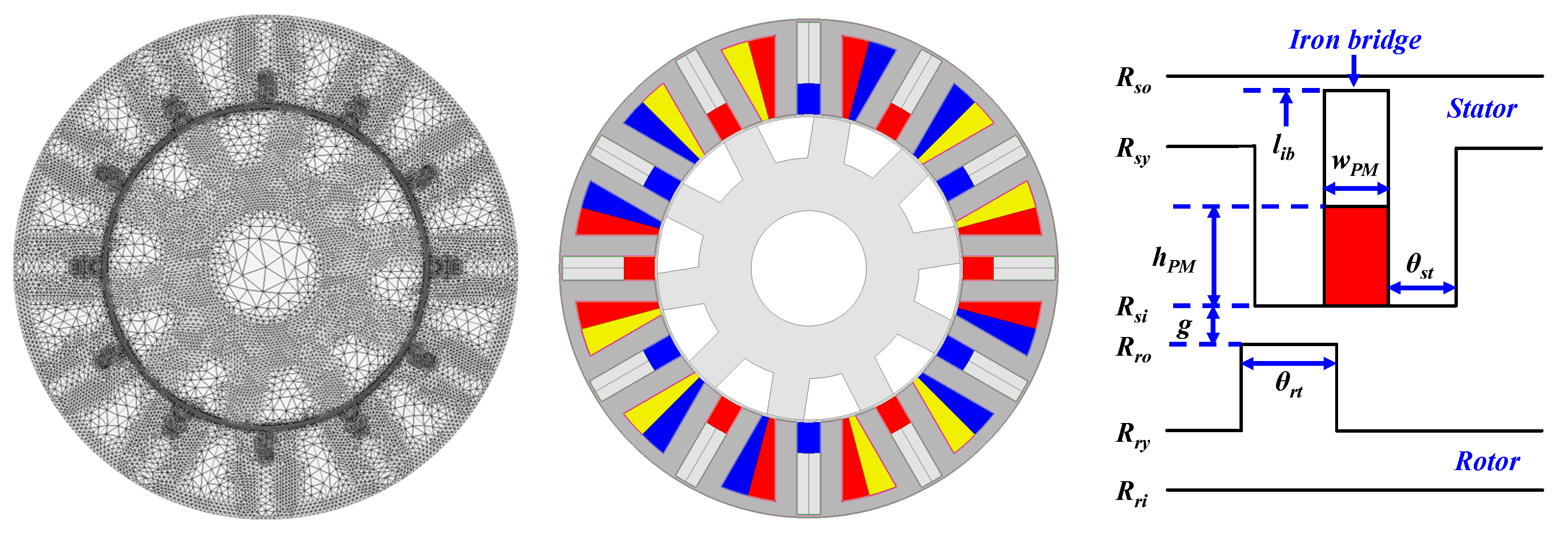
2. Machine Topology and Operation Principle

The primary machine topology to be investigated in this paper is shown in Figure 1a,b, which is a conventional hybrid excited switched flux (HESF) machine with iron bridges [24]. By changing the value of the hybridization ratio k, other machine topologies can be obtained, as shown in Figure 1c,d.
As previously mentioned, the hybridization ratio k can be any value between 0 to 1. Figure 1c shows a conventional switched flux permanent magnet (SFPM) machine, which can be perceived as an HESF machine with k = 0. In the SFPM machine, the field coils are removed and only PMs are used for field excitation. Therefore, k = 0 essentially represents permanent magnet synchronous machines (PMSMs). However, different from the HESF machine, the SFPM machine does not utilize iron bridges. This is due to the fact that iron bridges can provide an additional flux path for field coils in the HESF machine and the purpose of using iron bridges is to better regulate the air gap magnetic flux. While for the SFPM machine, iron bridges could lead to increased leakage flux of stator-PMs and therefore they are removed, although they are beneficial for improving the mechanical structure of stator laminations. Figure 1d shows a conventional switched flux wound field (WFSF) machine with field/armature coils of two slot pitches (F2A2), which can be perceived as an HESF machine with k = 1. In the WFSF machine, the PMs are removed and only field coils are used for field excitation. Therefore, k = 1 essentially represents wound field synchronous machines (WFSMs). Figure 1a,b show conventional HESF machines, where the field winding and PMs work collaboratively for field excitation. The only difference between these two machines is the hybridization ratio k and, therefore, the respective contribution of the field coils and the PMs to the total field excitation is different. In Figure 1a, k is 0.3 and it can be perceived as the mild hybrid since the contribution of PM flux is predominant. While in Figure 1b, k is 0.6 and it can be perceived as the heavy hybrid since the contribution of the wound field flux is obviously increased compared to the case shown in Figure 1a.
All of these machines shown in Figure 1 feature doubly salient topology and the magnetic gearing effect exists. Due to the salient pole rotor’s modulation effect on stator magnetomotive forces (MMFs), abundant field harmonics exist in the air gap. Therefore, near-sinusoidal back-EMF is produced in the phase winding when the salient pole rotor rotates. As such, electromagnetic torque can be generated when the appropriate phase winding current is applied.

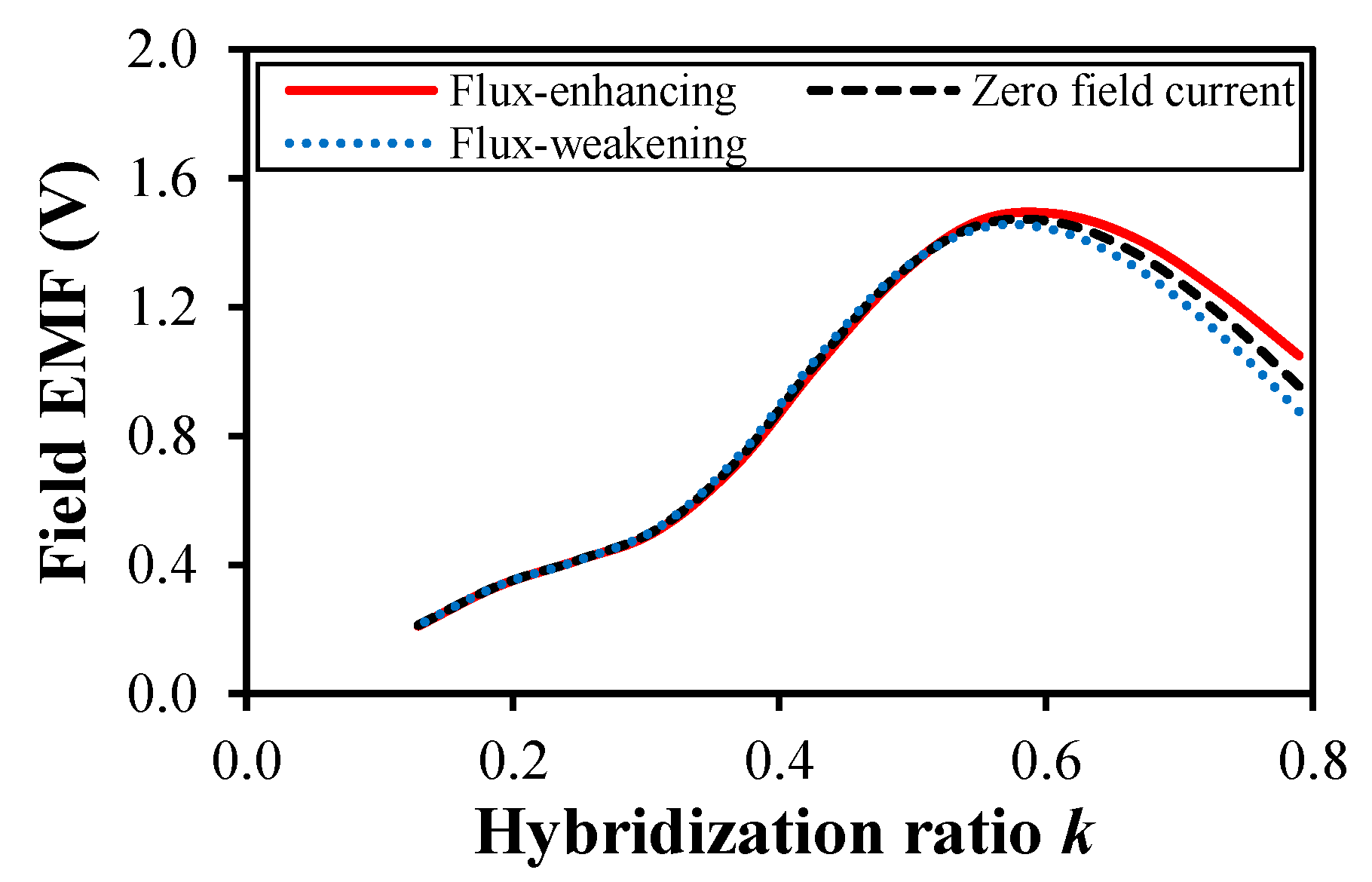
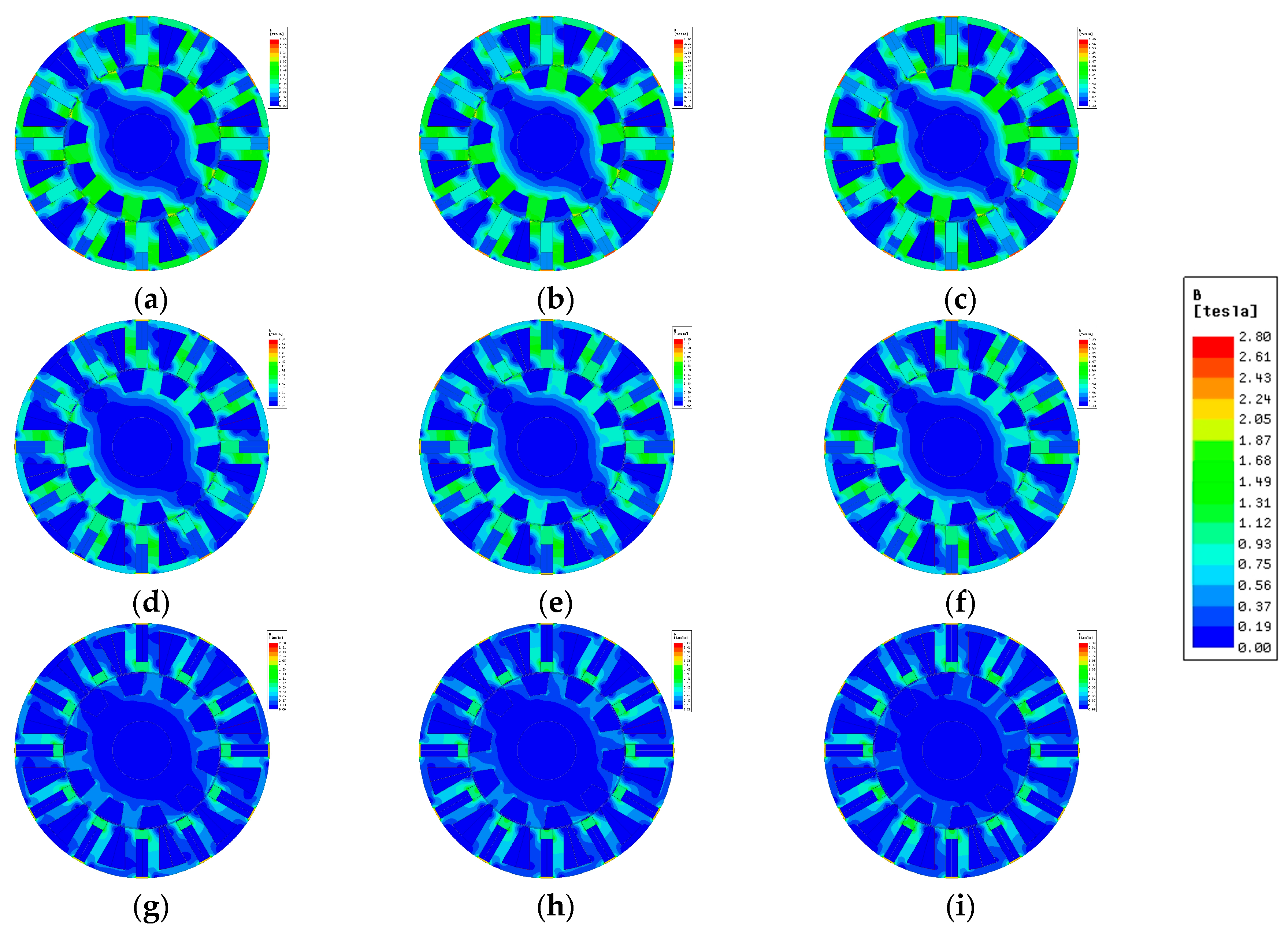
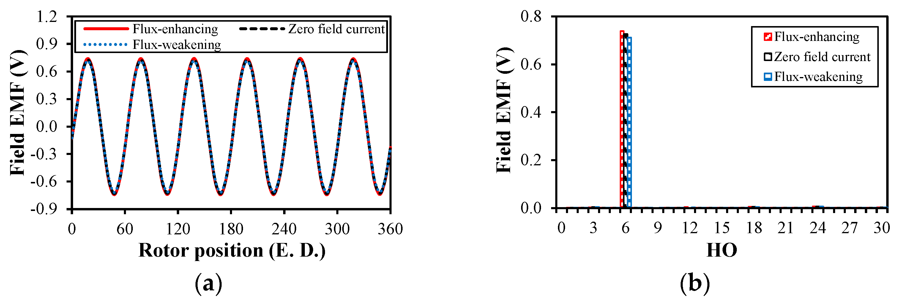
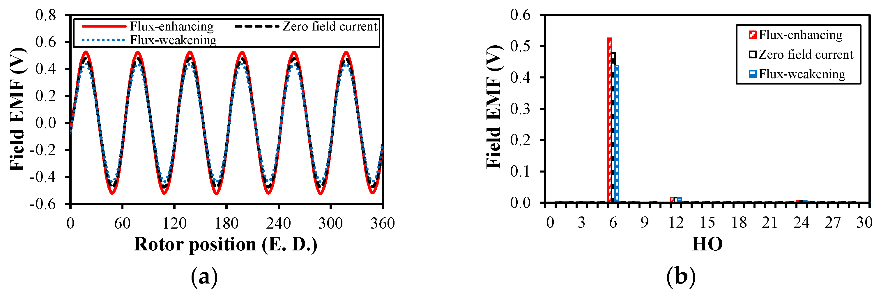
3. Influence of Hybridization Ratio on Field Back-EMF Ripple in HESF Machines

To comprehensively illustrate the influence of the hybridization ratio k on the field back-EMF ripple in HESF machines, the field back-EMF ripple against the hybridization ratio k under various operating conditions is covered in the following section. Besides, to reveal the relationship between the magnetic saturation and the field back-EMF ripple, the field back-EMF of HESF machines in flux-enhancing, zero field current, and flux-weakening modes is also presented. It should be noted that all of the simulation results presented in this paper were obtained using the commercial finite element analysis (FEA) software Ansys Maxwell 18.2. In the software, 2D FEA and transient mode are utilized for the investigation.
For the field back-EMF ripple, it is difficult to accurately predict its value due to magnetic saturation, end effects, flux leakage, etc. However, its harmonic orders under different operating conditions can be accurately predicted using the analytical method. The predicted harmonic orders can be used to indicate the peak-to-peak value of the field back-EMF ripple and hence its influence on the machine system. The field back-EMF with higher harmonics usually exhibits a lower amplitude, while the field back-EMF with lower harmonics usually exhibits a higher amplitude. It should be noted that the hybridization ratio k does not affect the field back-EMF harmonic orders but the amplitude whilst the harmonic orders are subject to different operating conditions. Under the open-circuit condition, the existing field back-EMF harmonic order i can be expressed as follows:
i = LCM ( N s , N r ) N r k
where Ns and Nr are the stator and rotor pole numbers, respectively. k is a positive integer.
Under the armature reaction condition, the field back-EMF ripple due to three-phase armature currents Varmature can be expressed as follows:
v a r m a t u r e ( θ e ) = j = 1 , 2 , 3 , 3 2 I p N r Ω M j k w j × { ( j 1 ) sin ( ( j 1 ) θ e + β j θ a ) ,   w h e n   j = 3 m 2 ( j + 1 ) sin ( ( j + 1 ) θ e + β j + θ a ) ,   w h e n   j = 3 m 1 0 ,   w h e n   j = 3 m
where Ip is the peak phase current. Ω is the mechanical speed of the rotor. Mjkwj is the amplitude of the jth harmonic of mutual inductance. kwj is the winding factor of the jth harmonic. βj is the corresponding initial phase. θa is the phase current angle. θe is the rotor electrical position.
Under the on-load condition, the field back-EMF ripple is the synthesis of that under the no-load and armature reaction conditions and thus the back-EMF harmonic orders under different conditions can be predicted with the aid of Equations (1) and (2).

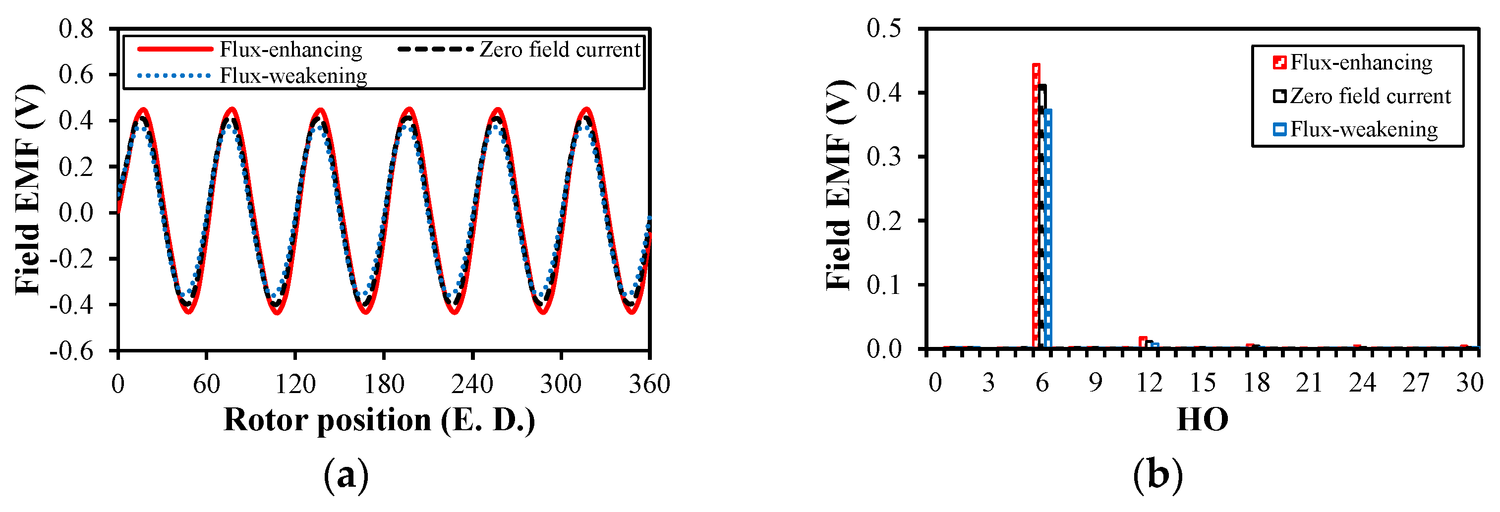
3.1. Open-Circuit Condition

Figure 2 shows the peak-to-peak field back-EMF ripple (Vpp) under the open-circuit condition against the hybridization ratio k in flux-enhancing, zero field current, and flux-weakening modes. It should be noted that the current density in the field winding is +5 A/mm2 in flux-enhancing mode while −5 A/mm2 is applied in flux-weakening mode. In zero field current mode, there is no current in the field winding and only the PMs are active for field excitation. With the change in the hybridization ratio k, the respective volume of the PMs and field coils changes accordingly since the total volume for the PMs and field coils is kept constant. Therefore, the MMF generated by the field winding and the PMs also changes with the change in the hybridization ratio k. From Figure 2, the open-circuit Vpp first increases and then decreases with k in flux-enhancing, zero field current, and flux-weakening modes. Therefore, a maximum value of Vpp exists at k = 0.6 for all three operating modes.
Figure 3 illustrates the HESF machine’s working mechanism, where the main flux paths produced by the field coils and PMs are labeled, respectively. For hybrid excited machines, they normally operate in three different modes, i.e., flux-enhancing, flux-weakening, and PM only. In PM only mode, the field current is zero and the air gap field is only excited by the PMs. In flux-enhancing mode, positive field current is injected into the field winding and the flux produced by the positive field current is used to enhance the air gap field, as illustrated in Figure 3a. With an enhanced air gap field, the phase back-EMF and thus the electromagnetic torque can be increased. While in flux-weakening mode, negative field current is injected into the field winding and the flux produced by the negative field current is used to weaken the air gap field, as illustrated in Figure 3b. With the flux-enhancing current, the air gap PM flux is enhanced and the PM leakage flux around the iron bridge area is reduced. By contrast, with flux-weakening current, the air gap PM flux is weakened and the PM leakage flux around the iron bridges is increased. The HESF machine’s no-load flux-density distributions under different hybridization ratios and operating modes are shown in Figure 4.
The trend of the three curves shown in Figure 2 can be explained by the diagrams illustrated in Figure 3 and the flux density distributions presented in Figure 4.
When k is small, the total field slot is almost occupied by the PMs and thus the PMs’ MMF is considerably higher than the MMF of the field winding. Consequently, as shown in Figure 4a–c, the DC winding’s flux path’s magnetic saturation is severe, which results in relatively lower open-circuit Vpp due to lower amplitudes of self-inductance harmonics and mutual-inductance harmonics, as evidenced in Figure 2. Besides, it can also be observed in Figure 2 that the open-circuit Vpp in different operating modes is almost unchanged when k is small and the three curves largely overlap. This is due to the fact that the MMF of the PMs is dominant when k is small and the magnetic saturation level of the field winding’s flux path can almost not be adjusted by the negligible MMF of the field winding.
With the increase in k, the volume of the field winding is increased while that of the PMs is reduced. Therefore, the field winding’s MMF becomes increasingly dominant, especially when k is large. As such, the magnetic saturation of the field winding’s flux path is mitigated, as shown in Figure 4d–f, and a higher Vpp can be observed as k increases, as evidenced in Figure 2. As k continues to increase, the magnetic saturation level of the field winding’s flux path is significantly mitigated, as illustrated in Figure 4g–i, since the MMF produced by the PMs rapidly decreases. However, Vpp starts to fall as k continues to increase since the total MMF of the field winding’s magnetic circuit is reduced due to the low energy density of the field winding. Therefore, Vpp reaches its maximum value with k at around 0.6 for different modes.
When k is large, the MMF of the field winding becomes effective and Vpp under flux-enhancing current is higher than that under zero field current and flux-weakening current with the same k, as shown in Figure 2. As illustrated in Figure 3, with flux-enhancing current, the PM leakage flux around the iron bridge area is reduced and the magnetic saturation level of the field winding’s flux path is alleviated. Therefore, a higher Vpp can be found in flux-enhancing mode. By contrast, with zero field current or flux-weakening current, the PM leakage flux path is enhanced and the magnetic saturation level in the corresponding area is intensified. As such, Vpp in these two operating modes is lower than that under flux-enhancing current due to different magnetic saturation levels.
The field back-EMF and the FFT results under the no-load condition with k = 0.61 in different operating modes are shown in Figure 5. In Figure 5a, the back-EMF waveforms in different modes are almost coincident, i.e., tiny differences in Vpp, which agrees well with the aforementioned theoretical analyses. Besides, the field back-EMF waveforms in different modes are periodical and the 6th back-EMF harmonic has the highest amplitude amongst all of the harmonics, as shown in Figure 5b. In theory, apart from the main 6th back-EMF harmonic, the 12th, the 18th, the 24th, the 30th…may exist in the field winding, albeit with very low amplitude. In other words, the field back-EMF harmonics with 6N order (where N is a positive integer) can exist in the field winding while other harmonic orders (HOs) are counteracted. However, it is worth noting that the hybridization ratio and the operating mode do not change the field back-EMF harmonic orders, which is essentially determined by the machine topology, the combinations of pole and slot numbers, etc.
Figure 6 shows the open-circuit field back-EMF waveforms and the FFT results of the HESF machine with k = 0.79 in different operating modes. As can be found in Figure 6a, Vpp in flux-enhancing mode is higher than that in zero field current and flux-weakening modes due to the magnetic saturation level in the field winding’s flux path, as previously mentioned. Similar to Figure 5b, the field back-EMF harmonic orders are not influenced by the hybridization ratio, but the amplitude of each harmonic may change due to the change in the total MMF and the magnetic saturation level, as shown in Figure 6b.

3.2. Armature Reaction Condition

Figure 7 shows the peak-to-peak field back-EMF ripple (Vpp) against the hybridization ratio k under the armature reaction condition, where the field excitations, i.e., the PMs and field winding, are absent and only armature currents are injected. The armature copper loss is fixed at 20 W by considering the thermal limits of the investigated HESF machine since the operating speed is 400 rpm and the copper loss is the main loss component. As such, an AC current with a root mean square (RMS) value of 12 A is applied for each phase. In Figure 7, the armature reaction Vpp decreases almost linearly with the increase in k, which indicates that the magnetic saturation level in the field winding’s flux path is almost unchanged. With the increase in k, the field winding’s slot area is enlarged, which results in a reduced rate of the field winding’s flux change, i.e., reduced Vpp, although there is no MMF produced by the field excitation.
Figure 8 shows the field back-EMF waveform and the FFT results for the HESF machine with k = 0.61 under the armature reaction condition. As shown in Figure 8a, similar to the condition of open circuit, the waveform of the field back-EMF is also periodic under the armature reaction condition. The field back-EMF harmonic orders attributed to the armature reaction are still 6N, as can be found in Figure 8b, but the main back-EMF harmonic is the 12th. Similarly, the hybridization ratio does not influence the field back-EMF harmonic orders under the armature reaction condition, but the amplitude of each harmonic may change due to the varied slot area for the field winding.

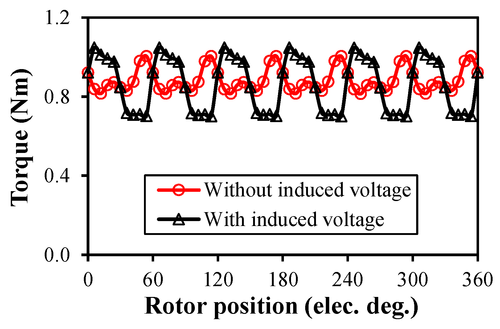
3.3. On-Load Condition

Figure 9 shows the peak-to-peak field back-EMF ripple (Vpp) under the on-load condition against the hybridization ratio k in flux-enhancing, zero field current, and flux-weakening modes. Under the on-load condition, the field current density is still 5 A/mm2 and the AC current’s RMS value in each phase is 12 A. In contrast to the no-load condition, the field back-EMF under on-load conditions is the synthesis of the back-EMF under both the open-circuit and armature reaction conditions. However, similar to the open-circuit condition, the on-load Vpp first increases and then decreases with k in all three operating modes, as shown in Figure 9.
When k is small, the PMs play a dominant role in the field excitation and thus the magnetic saturation level of the field winding’s flux path is severe, as can be found in Figure 10a–c. Therefore, a relatively lower on-load Vpp can be observed with a small k, whilst the on-load Vpp under different modes is almost unchanged due to the trivial MMF produced by the field current. When k increases, the on-load Vpp first increases as well in all three modes due to the alleviated magnetic saturation resulting from the reduced PMs’ MMF, as shown in Figure 10d–f.
As k continues to increase, the field winding’s MMF plays a dominant role in the field excitation and the MMF produced by the PMs is significantly reduced, especially when k is large. As such, the on-load Vpp starts to fall in all three modes due to the reduced total MMF produced by the PMs and the field current. However, different from the condition with a small k, the on-load Vpp in flux-enhancing mode is higher than that under zero field current or flux-weakening current when k is large. Similar to the condition of open circuit, this can be explained from the perspective of the magnetitic saturation level in the field winding’s flux path, which is different in the three operating modes due to the enhanced MMF of the field winding, as shown in Figure 10g–i.
Figure 11 shows the on-load field back-EMF waveforms and the FFT results of the HESF machine with k = 0.61 in different operating modes. As previously mentioned, the on-load field back-EMF is the synthesis of the field back-EMF under the no-load and armature reaction conditions. Therefore, the on-load field back-EMF waveforms in different modes are still periodical, as can be found in Figure 11a, and the 6th is the main harmonic with k = 0.61, as shown in Figure 11b. Moreover, the on-load field back-EMF harmonic orders are still 6N, as can be found in Figure 11b, which is attributed to the open-circuit and armature reaction back-EMF harmonics.
Additionally, the back-EMF waveforms in different modes are almost coincident with a small k, which agrees well with the results shown in Figure 9. Similar to the conditions of open circuit and armature reaction, the hybridization ratio and the operating mode do not change the field back-EMF harmonic orders.
Figure 12 shows the on-load field back-EMF waveforms and the FFT results of the HESF machine with k = 0.79 in different operating modes. As can be found in Figure 12a, Vpp in flux-enhancing mode is higher than that in zero field current and flux-weakening modes due to the magnetic saturation level in the field winding’s flux path, as explained for Figure 9. Similar to Figure 11b, the field back-EMF harmonic orders are not influenced by the hybridization ratio, but the amplitude of each harmonic may change due to the change in the total MMF and the magnetic saturation level, as shown in Figure 12b.

4. Comparison of HESF and WFSF Machines

In Section 3, the influence of the hybridization ratio k on the field back-EMF ripple of the HESF machine in various operating modes are comprehensively studied. In this section, a comparative study of the field back-EMF in both HESF and WFSF machines is presented. It should be noted that both the PMs and field coils are employed as excitation sources in HESF machines while only field coils are employed as the excitation source in WFSF machines. The difference in excitation sources leads to significant differences in the field back-EMF characteristics of HESF and WFSF machines. As illustrated in Figure 1, the HESF machine becomes an SFPM machine when k = 0 and thus the field back-EMF does not exist. When 0 < k < 1, the machine is the HESF machine, and its field back-EMF against k was investigated in Section 3. When k = 1, the HESF machine becomes a WFSF machine, as shown in Figure 1d, and its field back-EMF will be comparatively investigated in this section. For WFSF machines, they are developed from conventional SFPM machines, where the PMs are totally replaced by DC coils. WFSF machines feature salient stator/rotor-pole and both AC and DC coils are positioned in the stator side. Therefore, WFSF machines are suitable for very high-speed applications and their field-regulating capabilities is excellent due to solely DC winding excitation. Similar to conventional SFPM machines, WFSF machines exhibit sinusoidal phase back-EMF and thus the output torque is stable. Another advantage of WFSF machines is their low cost, which is extremely important for low-cost applications, e.g., domestic appliances. However, the iron loss for WFSF machines should be carefully considered, especially under high speeds, since the air gap field harmonics are abundant due to the doubly salient structure, i.e., the field modulation effect. To make a fair comparison, the geometric parameters of the HESF and WFSF machines are kept the same and the main difference lies in the excitation source. Similar to the HESF machine, for the investigated WFSF machine, the copper loss of the three-phase armature windings is fixed at 20 W and a 5 A/mm2 field current density is applied.

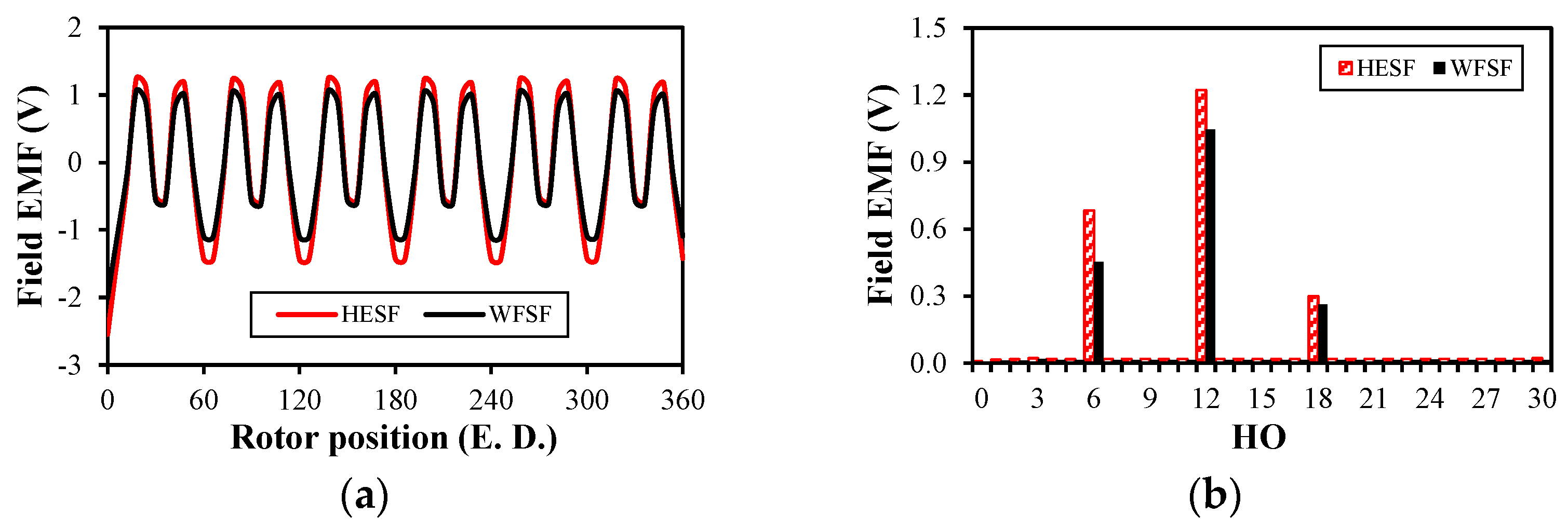
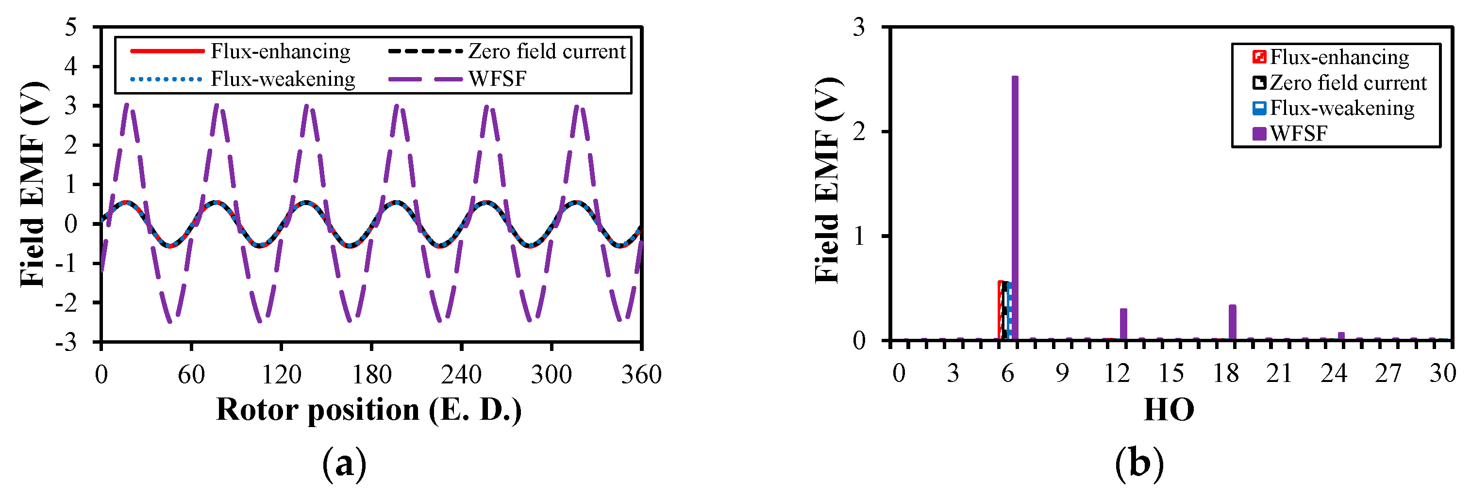
4.1. Open-Circuit Condition

Figure 13 compares the open-circuit field back-EMF in both HESF and WFSF machines. As can be found in Figure 13a, the WFSF machine’s open-circuit Vpp is relatively lower than the HESF machine’s Vpp with k = 0.61. Although the magnetic saturation level of the field winding’s flux path in the WFSF machine is significantly mitigated due to the elimination of the MMF of the PM, the total field’s MMF is substantially reduced as well, which results in a relatively lower Vpp in the WFSF machine. However, as shown in Figure 13b, the open-circuit field back-EMF harmonic contents in the WFSF machine are not changed, i.e., 6N.

4.2. Armature Reaction Condition

Figure 14 compares the armature reaction field back-EMF in both HESF and WFSF machines. In Figure 14a, the WFSF machine’s armature reaction Vpp is slightly lower than the HESF machine’s Vpp with k = 0.61. Under the armature reaction condition, all other parameters are kept the same in both machines, except the field winding slot area. Therefore, the armature reaction Vpp in the WFSF machine is slightly lower due to the enlarged field winding slot area, although the saturation level in both machines is almost unchanged, as analyzed in Figure 7. Besides, as shown in Figure 14b, the armature reaction field back-EMF harmonic contents of both machines are the same, i.e., 6N.

4.3. On-Load Condition

Figure 15 compares the on-load field back-EMF in both HESF and WFSF machines. As shown in Figure 15a, different from the conditions of open circuit and armature reaction, the WFSF machine’s on-load Vpp is considerably larger than the HESF machine’s Vpp with k = 0.61. However, as shown in Figure 15b, the on-load field back-EMF harmonic contents of both machines are the same, i.e., 6N.
As previously mentioned, the on-load field back-EMF is the superposition rather than simple addition of the back-EMF components under the open-circuit and armature reaction conditions. In fact, each field back-EMF component is essentially determined by the field winding’s flux path’s magnetic saturation and MMF levels. Compared with the HESF machine’s flux density distributions shown in Figure 4 and Figure 10, the magnetic saturation level of the WFSF machine in various operating modes is considerably lower, as illustrated in Figure 16. Therefore, due to severe local magnetic saturation in the HESF machine, the illustrated open-circuit and armature reaction back-EMF components are essentially reduced under the on-load condition, which leads to a relatively lower on-load Vpp. Compared with the HESF machine, the on-load Vpp of the WFSF machine is considerably increased since the magnetic saturation is considerably alleviated by removing the PMs’ MMF. It is also revealed from the above analyses that the type of field excitation source does not affect the field back-EMF harmonics.
In theory, the field current is constant and free from any current harmonics if the field back-EMF ripple does not exist. However, as shown in Figure 17, the actual field current is not constant but suffers from many current harmonics due to the field back-EMF ripple. The unstable field current leads to unstable field excitation, additional phase back-EMF harmonics, and thus increased torque ripple and even deceased average torque. As shown in Figure 18, the torque ripple is increased by 86.6% and the average torque is decreased by 2.4% due to the influence of the field back-EMF ripple.

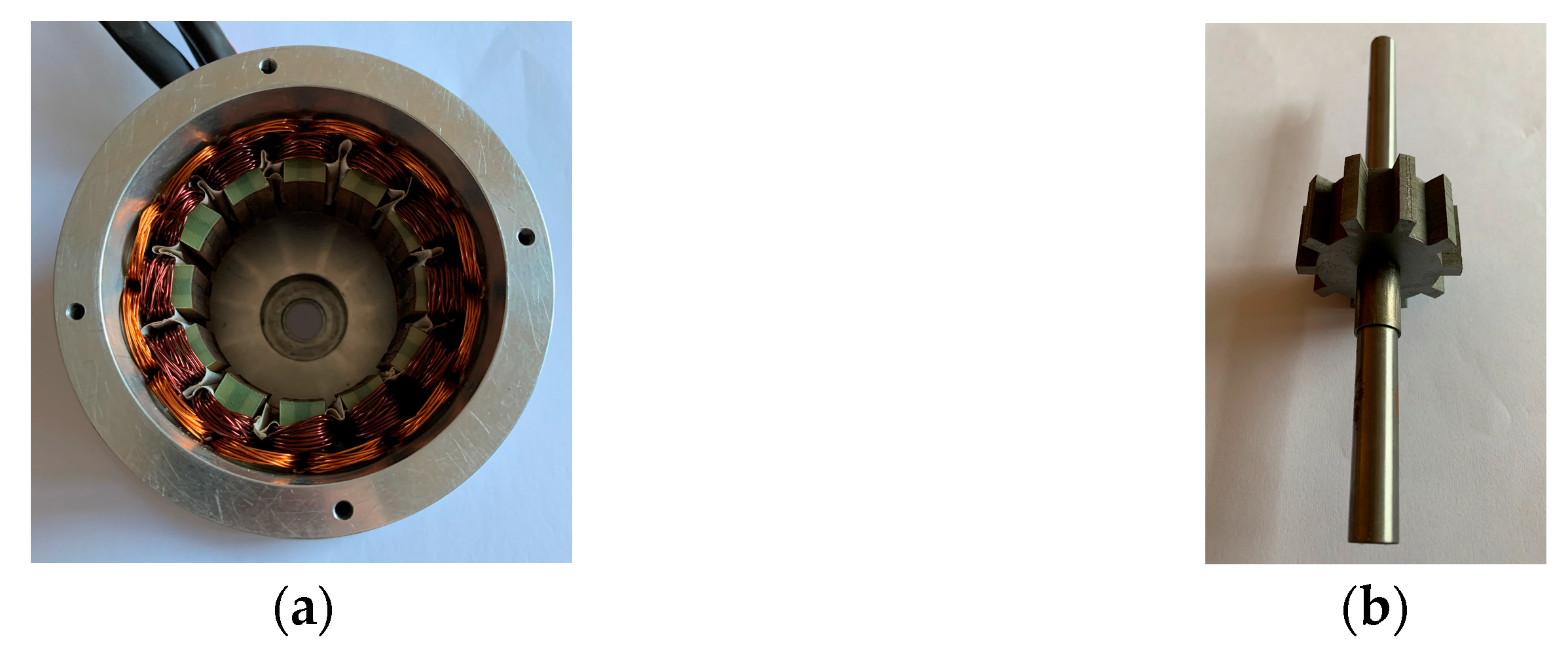
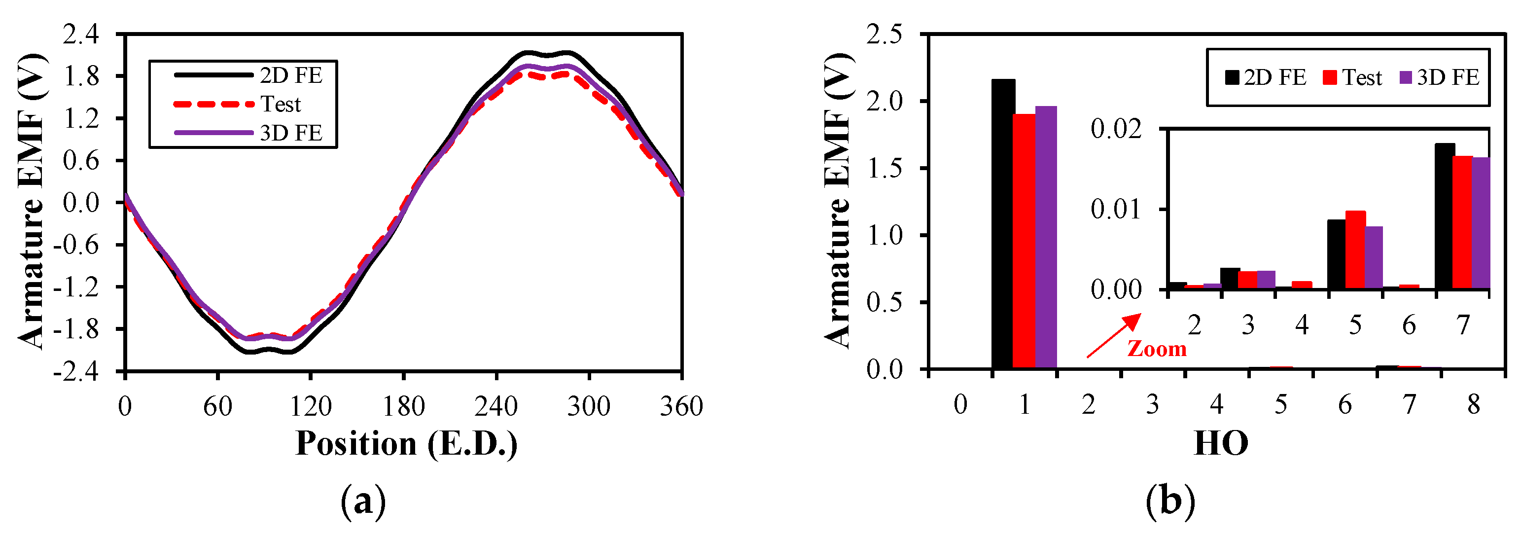
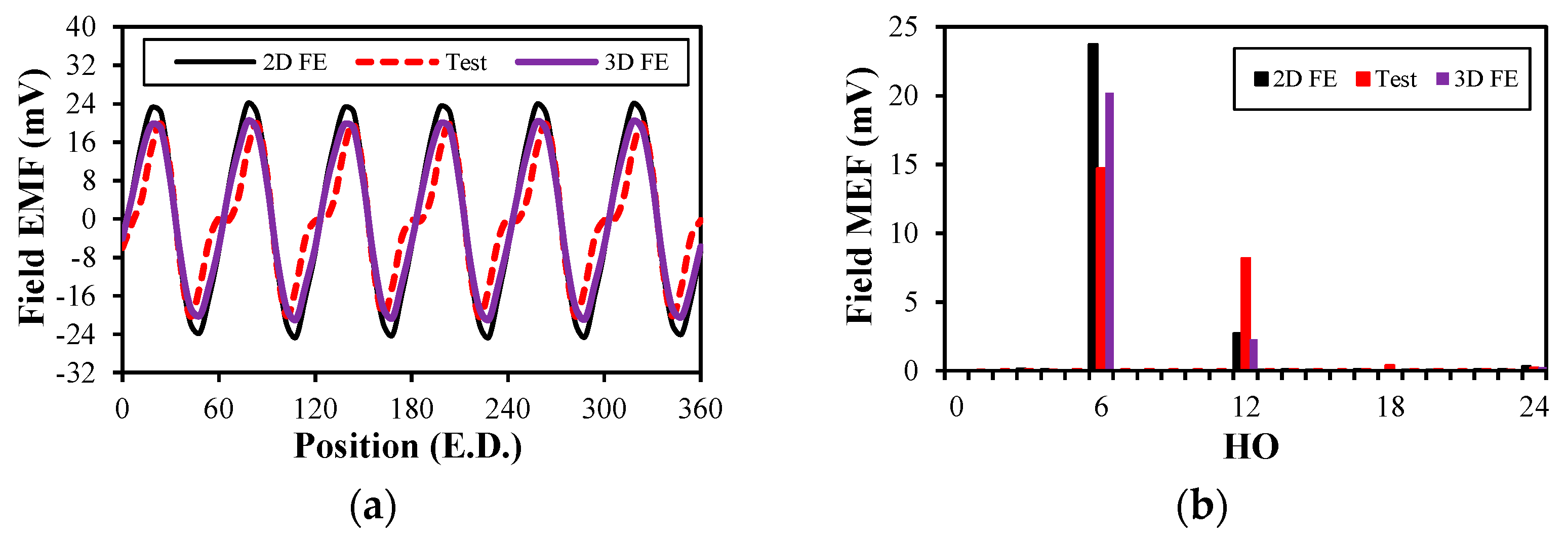
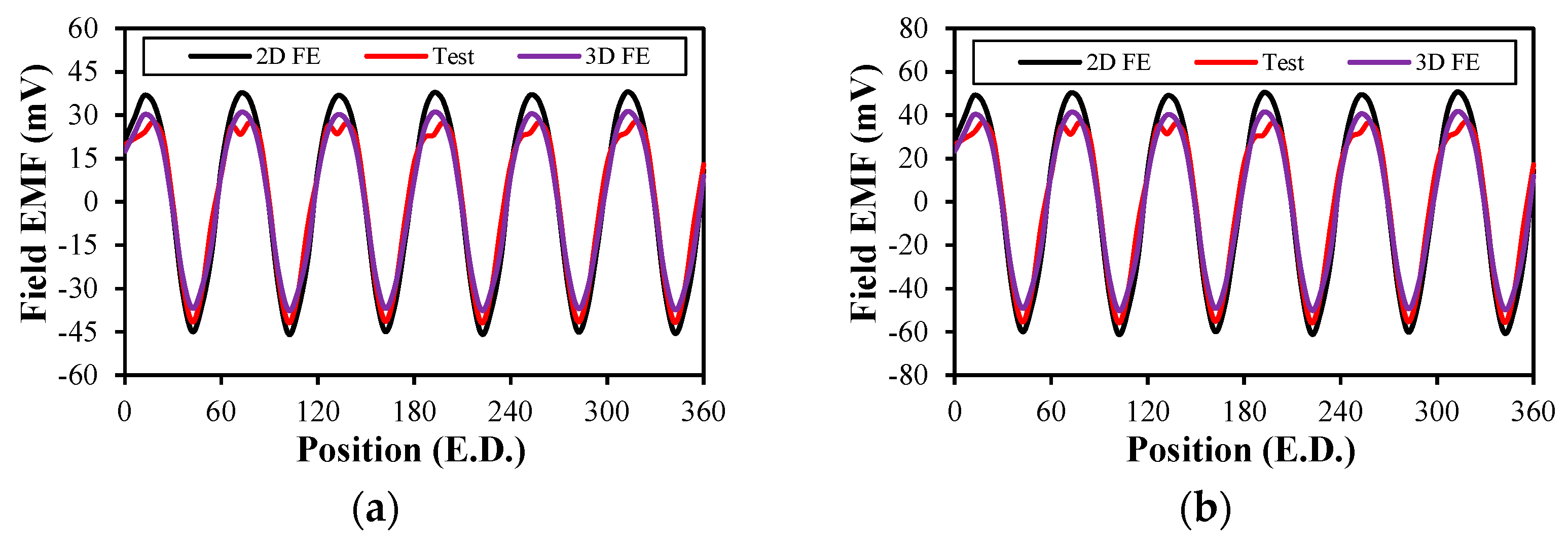
5. Experimental Verification

As shown in Figure 19, to verify the theoretical results calculated using the finite element method, a 12/10-pole HESF machine with the hybridization ratio k = 0.56 was prototyped. For the prototype machine, the stator contained the PMs and DC and AC windings. The coil pitch of the DC and AC windings was one stator slot and the magnetization direction of the PMs was circumferential. Similar to switched reluctance machines, the rotor was very simple and only composed of laminations, which was beneficial for thermal management and high-speed operation. The stator outer and inner radius of the prototype machine were 45 mm and 27 mm, respectively, whilst the active axial length of the silicon steel laminations was 25 mm. Besides, the height of the PMs was 7.5 mm and an iron bridge of 1 mm was employed to provide an additional flux path for the DC winding, which resulted in the hybridization ratio k being around 0.56. The main parameters of the prototype machine are summarized in Table 1. Figure 20 illustrates the test rig for performing experiments with the prototype machine. The mechanical components of the test rig mainly included the DC load machine, the torque sensor, the position sensor, and the prototype machine.
Open-circuit tests of the prototype machine were first conducted. As shown in Figure 21, the simulated and tested armature back-EMFs and the FFT results of the prototype machine were compared, in which the rotor rotated at 400 rpm and the prototype was in zero field current mode (Idc = 0 A). Only the results of one phase are shown in Figure 21 for clear comparison. It can be observed in Figure 21a that the measured phase back-EMF was around 14.5% lower than that predicted by 2D FEA, which was mainly due to the 3D end effect, as evidenced by the 3D FEA calculations shown in Figure 21. The stack length of the prototype machine was only 25 mm and the influence of the end effect would be more severe if the stack length was too short. Usually, only a 2D FEA model is employed to balance calculation accuracy and efficiency. However, to illustrate the influence of the 3D end effect, a 3D FEA model was also employed and simulated in this section. It can be found from Figure 21b that the measured phase back-EMF harmonics agreed well with those predicted by FEA. Overall, the open-circuit test results agreed well with the finite element simulated results and the error was mainly attributed to the 3D end effect and also manufacturing tolerance.
Although the induced back-EMF in the field winding was very similar to the armature back-EMF, the testing method for the field back-EMF was different from that of the armature back-EMF. The field coils were first divided into two groups, and each group consisted of 6 field coils. The field coils in one group, i.e., f1, f3, f5, f7, f9, f11, were connected together to form the field winding, while the field coils in the other group, i.e., f2, f4, f6, f8, f10, f12, were kept open-circuited. When measuring the induced back-EMF in the field winding, the first winding group, 6 coils, was loaded with twice the rated current to keep the field winding’s MMF unchanged. It was shown that the electromagnetic performance of the investigated machine was not affected if the total field winding’s MMF was unchanged. Then, the induced back-EMF waveform in any field coils of the second group could be measured since these coils were open-circuited and the influence of the DC power supply on the measurement of the field winding-induced back-EMF could be eliminated. When the induced back-EMF in one field coil was obtained, the induced back-EMF in the rest of the field coils could be obtained by the corresponding phase shift according to their spatial electric positions. As such, the induced back-EMF in the field winding could be obtained by adding all of the field coil back-EMFs. It should be mentioned that for both the open-circuit and on-load tests, the mechanical speed of the rotor was 400 rpm and the machine operated in flux-enhancing mode. Under the conditions of open circuit and on load with flux-enhancing current, the tested and FEA-predicted results of the field back-EMFs are shown in Figure 22 and Figure 23, respectively. It can be observed in Figure 22a Figure 23a that the measured field back-EMF was lower (no-load: 16%, on-load: 18%) than that predicted by 2D FEA, which was still mainly due to the 3D end effect, as verified by the 3D FEA results shown in Figure 22 and Figure 23. However, in Figure 22b and Figure 23b, the main field back-EMF harmonics, e.g., 6th and 12th, are clearly observed from the measured harmonic spectra, which further validated the theoretical analysis. Apart from the 3D end effect, the observed errors between the FEA-predicted and test results were mainly caused by manufacturing imperfections, assembly tolerances, and measuring errors. However, it reveals that the measured field back-EMF harmonic orders under both the no-load and on-load conditions were 6N with flux-enhancing current, which validated the theoretical results shown in Section 3. Figure 24 shows the tested and simulated on-load field back-EMF waveforms under different operating speeds. It revealed that the field back-EMF was proportional to the rotor speed and the 3D end effect could lead to obvious differences between the 2D FEA-predicted and test results. The 2D FEA model of the simulated machine is provided in Figure 25.

6. Conclusions

The paper reveals the relationship between the hybridization ratio k and the field back-EMF ripple in HESF machines under different operating conditions. The analytical method, the finite element method, and the experimental method are used to investigate and validate the field back-EMF ripple. In this paper, the field back-EMF of the HESF machine with flux-enhancing current, zero field current, and flux-weakening current is first investigated under different conditions. It reveals that the open-circuit and on-load Vpp first increases and then decreases with k in all three operating modes and thus maximum value of the on-load and no-load Vpp exists. Such a phenomenon is jointly caused by the local magnetic saturation and total MMF level. Besides, with the increase in k, the available field winding slot area is increased and the armature reaction Vpp decreases almost linearly. When k is small, the open-circuit and on-load Vpp in different modes is almost unchanged. However, when k is large, the open-circuit and on-load Vpp with flux-enhancing current is higher than that with zero field current and flux-weakening current due to the eased local magnetic saturation level in the field winding’s flux path. Moreover, it shows that field back-EMF harmonic orders can serve as an indicator of its peak-to-peak value and influence on machine systems. The hybridization ratio k does not affect the back-EMF harmonic orders but their amplitudes under different conditions due to magnetic saturation. By comparing the field back-EMF in the HESF and WFSF machines, it reveals that the WFSF machine’s on-load Vpp is considerably larger than the HESF machine’s Vpp. This is mainly due to the fact that the mutual inductance harmonics between the AC and DC windings under the on-load condition in WFSF machines are significantly increased compared to HESF machines since the magnetic saturation in WFSMs is considerably alleviated by removing the PMs’ MMF. Additionally, the field back-EMF harmonic orders, i.e., 6N in the HESF and WFSF machines, are not influenced by the hybridization ratio, the operating mode, or the type of field excitation source.
As previously mentioned, a higher local magnetic saturation level is beneficial for suppressing the field back-EMF ripple while it is detrimental for improving the flux-regulating capability. Therefore, in future work, investigations can be extended to multi-objective optimization of HESF machines by considering both the field back-EMF and the air gap flux-regulating capability. Besides, the conclusions drawn in this paper can serve as a reference for other HEMs.

Author Contributions

Conceptualization, X.S. and R.H.; methodology, X.S. and R.H.; validation, X.S., R.H., and R.S.; formal analysis, X.S., R.H., and R.S.; investigation, X.S., R.H., and R.S.; resources, Z.Y.; data curation, X.S. and Z.Y.; writing—original draft preparation, X.S.; writing—review and editing, R.H., R.S., and Z.Y.; visualization, R.H., R.S., and Z.Y.; supervision, X.S.; project administration, X.S.; funding acquisition, X.S. All authors have read and agreed to the published version of the manuscript.

Funding

This research was funded in part by the National Key Research and Development Program of China under Project 2023YFB2406400, in part by the National Natural Science Foundation of China under grant no. 52407035, in part by the Hebei Natural Science Foundation under Project E2023105080, and in part by the Beijing Institute of Technology Research Fund Program for Young Scholars under Project XSQD-202207004.

Data Availability Statement

The data that support the findings of this study are available from the corresponding author upon reasonable request.

Conflicts of Interest

The authors declare no conflicts of interest.

Abbreviations

The following abbreviations are used in this manuscript:
ICEsInternal combustion engines
HEVs/EVsHybrid/full electric vehicles
HEMsHybrid-excited synchronous machines
WFSMsWound field synchronous machines
DSBLDCDoubly salient brushless DC
HESFHybrid excited switched flux machines
SFPMMSwitched flux permanent magnet machine
PMSMsPermanent magnet synchronous machines
WFSFSwitched flux wound field machine
MMFsMagnetomotive forces
HOsHarmonic orders
RMSRoot mean square

References

  1. Zhu, Z.Q.; Howe, D. Electrical machines and drives for electric, hybrid, and fuel cell vehicles. Proc. IEEE. 2007, 95, 746–765. [Google Scholar] [CrossRef]
  2. Chan, C.C. The state of the art of electric, hybrid, and fuel cell vehicles. Proc. IEEE. 2007, 95, 704–718. [Google Scholar] [CrossRef]
  3. Bianchi, N.; Bolognani, S.; Carraro, E.; Castiello, M.; Fornasiero, E. Electric vehicle traction based on synchronous reluctance motors. IEEE Trans. Ind. Appl. 2016, 52, 4762–4769. [Google Scholar] [CrossRef]
  4. Cheng, M.; Hua, W.; Zhang, J.; Zhao, W. Overview of stator-permanent magnet brushless machines. IEEE Trans. Ind. Electron. 2011, 58, 5087–5101. [Google Scholar] [CrossRef]
  5. Chan, C.C.; Chau, K.T.; Jiang, J.Z.; Xia, W.; Zhu, M.; Zhang, R. Novel permanent magnet motor drives for electric vehicles. IEEE Trans. Ind. Electron. 1996, 43, 331–339. [Google Scholar] [CrossRef]
  6. Kamiya, M. Development of traction drive motors for the Toyota hybrid system. IEEE Trans. Ind. Appl. 2006, 126, 473–479. [Google Scholar] [CrossRef]
  7. Sato, Y.; Ishikawa, S.; Okubo, T.; Abe, M.; Tamai, K. Development of High Response Motor and Inverter System for the Nissan LEAF Electric Vehicle; SAE Technical Paper; SAE International: Warrendale, PA, USA, 2011. [Google Scholar]
  8. Wilden, R.; Gudergan, S.P. The impact of dynamic capabilities on operational marketing and technological capabilities: Investigating the role of environmental turbulence. J. Acad. Mark. Sci. 2015, 43, 181–199. [Google Scholar] [CrossRef]
  9. Soong, W.L.; Ertugrul, N. Field-weakening performance of interior permanent-magnet motors. IEEE Trans. Ind. Appl. 2002, 38, 1251–1258. [Google Scholar] [CrossRef]
  10. Amara, Y.; Vido, L.; Gabsi, M.; Hoang, E.; Ahmed, A.; Lecrivain, M. Hybrid excitation synchronous machines: Energy-efficient solution for vehicles propulsion. IEEE Trans. Veh. Technol. 2009, 58, 2137–2149. [Google Scholar] [CrossRef]
  11. Ali, Q.; Atiq, S.; Lipo, T.A.; Kwon, B.I. PM assisted, brushless wound rotor synchronous machine. J. Magn. 2016, 21, 399–404. [Google Scholar] [CrossRef]
  12. Chu, W.Q.; Zhu, Z.Q.; Zhang, J.; Liu, X.; Stone, D.A.; Foster, M.P. Investigation on operational envelops and efficiency maps of electrically excited machines for electrical vehicle applications. IEEE Trans. Magn. 2015, 51, 1–10. [Google Scholar] [CrossRef]
  13. Fukami, T.; Matsuura, Y.; Shima, K.; Momiyama, M.; Kawamura, M. A multipole synchronous machine with nonoverlapping concentrated armature and field windings on the stator. IEEE Trans. Ind. Electron. 2012, 59, 2583–2591. [Google Scholar] [CrossRef]
  14. Fukami, T.; Matsuura, Y.; Shima, K.; Momiyama, M.; Kawamura, M. Development of a low-speed multi-pole synchronous machine with a field winding on the stator side. In Proceedings of the International Conference on Electrical (ICEM), Rome, Italy, 6–8 September 2010. [Google Scholar]
  15. Afinowi, A.A.; Zhu, Z.Q.; Guan, Y.; Mipo, J.C.; Farah, P. Hybrid-excited doubly salient synchronous machine with permanent magnets between adjacent salient stator poles. IEEE Trans. Magn. 2015, 51, 1–9. [Google Scholar] [CrossRef]
  16. Cai, S.; Zhu, Z.Q.; Mipo, J.C.; Personna, S. A novel parallel hybrid excited machine with enhanced flux regulation capability. IEEE Trans. Energy Convers. 2019, 34, 1938–1949. [Google Scholar] [CrossRef]
  17. Gaussens, B.; Hoang, E.; Lecrivain, M.; Manfe, P.; Gabsi, M. A hybrid-excited flux-switching machine for high-speed DC-alternator applications. IEEE Trans. Ind. Electron. 2014, 61, 2976–2989. [Google Scholar] [CrossRef]
  18. Hoang, E.; Lecrivain, M.; Gabsi, M. A new structure of a switching flux synchronous polyphased machine with hybrid excitation. In Proceedings of the 2007 European Conference on Power Electronics and Applications, Aalborg, Denmark, 2–5 September 2007. [Google Scholar]
  19. Wu, Z.Z.; Zhu, Z.Q.; Wang, C.; Mipo, J.C.; Personnaz, S.; Farah, P. Reduction of open-circuit DC winding induced voltage in wound field switched flux machines by skewing. IEEE Trans. Ind. Electron. 2019, 66, 1715–1726. [Google Scholar] [CrossRef]
  20. Wu, Z.Z.; Zhu, Z.Q.; Wang, C.; Mipo, J.C.; Personnaz, S.; Farah, P. Analysis and reduction of on-load DC winding induced voltage in wound field switched flux machines. IEEE Trans. Ind. Electron. 2020, 67, 2655–2666. [Google Scholar] [CrossRef]
  21. Wu, Z.Z.; Zhu, Z.Q.; Hua, W.; Akehurst, S.; Zhu, X.F.; Zhang, W.T.; Hu, J.; Li, H.Y.; Zhu, J.M. Analysis and suppression of induced voltage pulsation in DC winding of five-phase wound-field switched flux machines. IEEE Trans. Energy Convers. 2019, 34, 1890–1905. [Google Scholar] [CrossRef]
  22. Wu, Z.Z.; Zhu, Z.Q.; Wang, C. Reduction of on-load dc winding-induced voltage in partitioned stator wound field switched flux machines by dual three-phase armature winding. IEEE Trans. Ind. Electron. 2022, 69, 5409–5420. [Google Scholar] [CrossRef]
  23. Yu, L.; Zhang, M.; Jiang, B. Reduction of field-winding-induced voltage in a doubly salient brushless dc generator with stator-damper winding. IEEE Trans. Ind. Electron. 2022, 69, 7767–7775. [Google Scholar] [CrossRef]
  24. Sun, X.Y.; Zhu, Z.Q. Investigation of DC winding induced voltage in hybrid-excited switched-flux permanent magnet machine. IEEE Trans. Ind. Appl. 2020, 56, 3594–3603. [Google Scholar] [CrossRef]
  25. Sun, X.Y.; Zhu, Z.Q.; Cai, S.; Wang, L.; Wei, F.R.; Shao, B. Influence of stator slot and rotor pole number combination on field winding induced voltage ripple in hybrid excitation switched flux machine. IEEE Trans. Energy Convers. 2021, 36, 1245–1261. [Google Scholar] [CrossRef]
  26. Sun, X.Y.; Zhu, Z.Q.; Wei, F.R. Voltage pulsation induced in DC field winding of different hybrid excitation switched flux machines. IEEE Trans. Ind. Appl. 2021, 57, 4815–4830. [Google Scholar] [CrossRef]
  27. Sun, X.Y.; Zhu, Z.Q. Analysis of open-circuit DC winding induced voltage in partitioned-stator hybrid-excited switched-flux machine. In Proceedings of the 2019 Fourteenth International Conference on Ecological Vehicles and Renewable Energies (EVER), Monte-Carlo, Monaco, 8–10 May 2019. [Google Scholar]
  28. Sun, X.Y.; Zhu, Z.Q. Analysis and suppression of on-load excitation winding voltage pulsating in partitioned-stator hybrid-excited switched-flux machine. In Proceedings of the 10th IET International Conference on Power Electronics, Machines and Drives (PEMD 2020), Nottingham, UK, 15–17 December 2020. [Google Scholar]
Figure 1. HESF machine with different hybridization ratios. (a) k = 0.3; (b) k = 0.6; (c) k = 0; (d) k = 1.
Machines 13 00473 g001
Figure 2. Open-circuit peak-to-peak field back-EMF ripple against the hybridization ratio k in flux-enhancing, zero field current, and flux-weakening modes.
Machines 13 00473 g002
Figure 3. Operation principle of the HESF machine. (a) Flux-enhancing; (b) Flux-weakening.
Machines 13 00473 g003
Figure 4. Flux density distributions under no load with different hybridization ratios and operating modes. (a) Flux-enhancing (k = 0.37); (b) Zero field current (k = 0.37); (c) Flux-weakening (k = 0.37); (d) Flux-enhancing (k = 0.61); (e) Zero field current (k = 0.61); (f) Flux-weakening (k = 0.61); (g) Flux-enhancing (k = 0.79); (h) Zero field current (k = 0.79); (i) Flux-weakening (k = 0.79).
Machines 13 00473 g004
Figure 5. Field back-EMF under no load with k = 0.61 in different operating modes (400 rpm). (a) Field EMF; (b) FFT.
Machines 13 00473 g005
Figure 6. Field back-EMF under no load with k = 0.79 in different operating modes (400 rpm). (a) Field EMF; (b) FFT.
Machines 13 00473 g006
Figure 7. Armature reaction peak-to-peak field back-EMF ripple against hybridization ratio k.
Machines 13 00473 g007
Figure 8. Armature reaction field back-EMF with k = 0.61 (400 rpm). (a) Field EMF; (b) FFT.
Machines 13 00473 g008
Figure 9. On-load peak-to-peak field back-EMF ripple against hybridization ratio k in flux-enhancing, zero field current, and flux-weakening modes.
Machines 13 00473 g009
Figure 10. On-load flux density distributions under different hybridization ratios and operating modes. (a) Flux-enhancing (k = 0.37); (b) Zero field current (k = 0.37); (c) Flux-weakening (k = 0.37); (d) Flux-enhancing (k = 0.61); (e) Zero field current (k = 0.61); (f) Flux-weakening (k = 0.61); (g) Flux-enhancing (k = 0.79); (h) Zero field current (k = 0.79); (i) Flux-weakening (k = 0.79).
Machines 13 00473 g010
Figure 11. On-load field back-EMF with k = 0.61 in different operating modes (400 rpm). (a) Field EMF; (b) FFT.
Machines 13 00473 g011
Figure 12. On-load field back-EMF with k = 0.79 in different operating modes (400 rpm). (a) Field EMF; (b) FFT.
Machines 13 00473 g012
Figure 13. Field back-EMF under no load in the HESF machine with k = 0.61 and k = 1 (400 rpm). (a) Field EMF; (b) FFT.
Machines 13 00473 g013
Figure 14. Comparison of armature reaction field back-EMF in the HESF machine with k = 0.61 and k = 1 (400 rpm). (a) Field EMF; (b) FFT.
Machines 13 00473 g014
Figure 15. Comparison of on-load field back-EMF in the HESF machine with k = 0.61 and k = 1 (400 rpm). (a) Field EMF; (b) FFT.
Machines 13 00473 g015
Figure 16. Flux-density distributions of the WFSF machine in different operating modes. (a) Open-circuit; (b) Armature reaction; (c) On-load.
Machines 13 00473 g016
Figure 17. Influence of field winding back-EMF on field current.
Machines 13 00473 g017
Figure 18. Influence of field winding back-EMF on output torque.
Machines 13 00473 g018
Figure 19. 12/10-pole HESF machine prototype. (a) Stator; (b) Rotor.
Machines 13 00473 g019
Figure 20. Test bench of the HESF machine prototype.
Machines 13 00473 g020
Figure 21. Armature back-EMFs in zero field current mode (400 rpm). (a) Field EMF; (b) FFT.
Machines 13 00473 g021
Figure 22. Open-circuit field back-EMF with flux-enhancing current (400 rpm). (a) Field EMF; (b) FFT.
Machines 13 00473 g022
Figure 23. On-load field back-EMF with flux-enhancing current (400 rpm). (a) Field EMF; (b) FFT.
Machines 13 00473 g023
Figure 24. On-load field back-EMF under different rotor speeds. (a) 600 rpm; (b) 800 rpm.
Machines 13 00473 g024
Figure 25. FEA model of the simulated HESF machine.
Machines 13 00473 g025
Table 1. Main parameters of the prototype machine.
ParametersValueParametersValue
Stator outer radius45 mmStator pole number12
Active axial length25 mmRotor pole number10
Air gap length0.5 mmIron bridge length1 mm
Rotor outer radius26.5 mmPM length7.5 mm
Disclaimer/Publisher’s Note: The statements, opinions and data contained in all publications are solely those of the individual author(s) and contributor(s) and not of MDPI and/or the editor(s). MDPI and/or the editor(s) disclaim responsibility for any injury to people or property resulting from any ideas, methods, instructions or products referred to in the content.

