Article

Numerical Analysis of the Structural Parameters on the Performance of Oil-Injected Rotary Vane Compressors

1
School of Advanced Manufacturing, Nanchang University, Nanchang 330000, China
2
Jiangxi Key Laboratory of Intelligent Robot, Nanchang 330000, China
3
Centre for Sustainable Energy Use in Food Chains, Institute of Energy Futures, Brunel University London, Uxbridge UB8 3PH, UK
4
Centre for Compressor Technology, City St George’s, University of London, 10 Northampton Square, London EC1V 0HB, UK
*
Author to whom correspondence should be addressed.
Machines 2025, 13(6), 456; https://doi.org/10.3390/machines13060456
Submission received: 27 March 2025 / Revised: 16 May 2025 / Accepted: 22 May 2025 / Published: 26 May 2025
(This article belongs to the Special Issue Advances in Positive Displacement Compressors, 2nd Edition)

Abstract

The performance improvement potential with the optimisation of vane geometry and port timing angle in oil-injected Rotary Vane Compressors (RVCs) is not yet fully understood. Commonly, studies have used single-phase CFD models without consideration of lubricating oil. However, the presented analysis uses a more complex oil–gas two-phase CFD model. A fully analytical grid generation method was used for discretisation of the rotor domain, and the numerical method was validated against the experimental results. Coupled with the analysis of the flow field, the effects of five vane parameters and four configurations of port timing angles on the compressor performance were studied. The results show that the baseline case of the RVC achieved the volumetric and adiabatic efficiencies of 95.4% and 62.3%, respectively, while the specific power was 9.47 kW/(m3·min−1), which is consistent with typical industrial RVCs. The RVC as a high-efficiency compressor highly relies on the vane tip clearance size. The baseline parameters of the vane geometry and the port timing angles are relatively reasonable, and further optimisation of vane thickness, vane tip radius, vane eccentric angle, vane tip eccentric angle, intake port closing angle and exhaust port closing angle contributes to 1.7% decrease in the specific power. Overall, the structural parameter optimisation carried out in this paper, combined with the operational parameter optimisation conducted in previous studies, leads to a power reduction of 5.6%.

1. Introduction

Positive displacement Rotary Vane Compressor (RVC) has the advantages of a compact structure, a wide range of operation pressures and advantageous performance [1]. For this reason, RVCs have been widely applied in refrigeration [2], air conditioning [3], heat pumps [4,5] and compressed air [6,7]. In the latter case, compressed air makes up around 10% of global electricity and is a vital energy consumer in the industrial field. RVC is one of the typical air compressors for a flow rate of less than 1000 m3/min and a discharging pressure within 7–12 bar [8]. This underscores its critical role in efforts to improve energy efficiency and reduce CO2 emissions. To meet the needs of energy-saving and high-performance compressors, it is increasingly critical to improve the performance and the efficiency of RVCs.
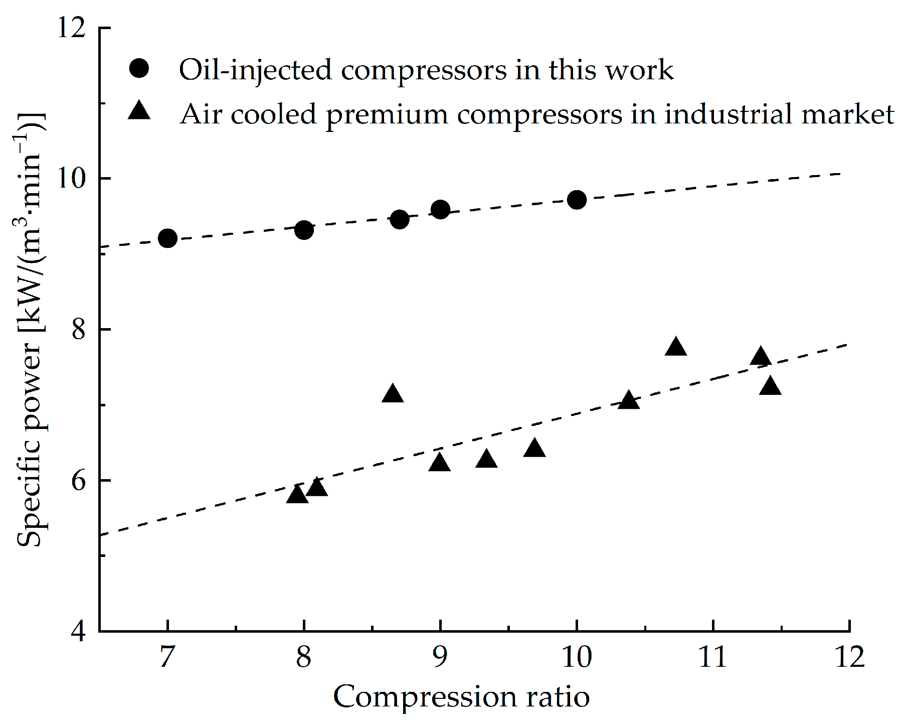
The efficiency of RVCs has been increasing over time and is predicted to reach 65.4% by 2025, with values approaching 70% at higher flow rates [9]. In the current industrial market, the specific power of RVCs increases with compression ratio, typically ranging from 6 to 7 kW/(m3·min−1), which is consistent with the description in Section 3.2 of this paper. Significant effort has been devoted to the structural optimisation of rotary vane machines (compressors, expanders and pumps) to improve their performance. Choo and Ooi [10] studied the vane chattering characteristics of a vane compressor by pressure measurement in working chambers, which can be resolved by increasing vane back pressure, using heavier vanes or enlarging the discharging port. Yang et al. [11] developed a kind of spring-loaded vane for vane expanders to enhance the reaction force at the vane tip, leading to smaller vane tip leakage. Jia et al. [12] enhanced the volumetric and isentropic efficiencies of a vane expander by introducing high-pressure gas into its vane slot. Experimental results showed a 27.2% performance improvement compared to the original prototype. Fatigati et al. [13] studied the impacts of the aspect ratio on the performance of vane pumps, which showed that increasing the radial dimension of the stator diameter allows for a reasonable reduction in the axial length at a given displacement, thereby reducing mechanical power losses. They also proposed a dual intake configuration of vane expanders to enhance volumetric and indicated efficiencies, as well as the use of lightweight graphite vanes to boost mechanical efficiency [14]. Natali et al. [15] proposed a novel elliptical vane tip profile by introducing additional geometric parameters that allow designers to improve robustness against manufacturing tolerances. Chen et al. [16] proposed a new quadratic spiral profile for the asymmetric stator of vane vacuum pumps to obtain a higher built-in volumetric ratio. In a second work, the latter authors indicated that a novel three-chamber configuration was feasible and better than the conventional single or double-chamber type from the perspective of pumping speed [17].
Developing innovative structures is another effective way to enhance the performance of vane machines. Choo and Ooi [18] developed a novel revolving vane compressor by adding additional free vanes. This modification enables the machine to produce several discharging cycles for every revolution, which helped to achieve higher volumetric flow rates and lower pressure fluctuations, as well as reduce the discharging noise level. Zhou et al. [19] developed a novel synchronous rotating compressor, leading to lower friction and wear by reducing the relative velocity of key friction pairs. Wang et al. [20] introduced a novel vane expander with a two-stage configuration for refrigeration systems. Their study found that under certain conditions, the expander can increase the coefficient of performance by up to 14.2%, outperforming traditional vapour-compression refrigeration systems. Gu et al. [21] numerically studied a novel RVC with a rotating cylinder and found that the friction losses at the vane tip and between the stator and rotor decreased by 0.25% and 10.23%, respectively. Shakya and Ooi [22] introduced an innovative design for a coupled dual-blade vane compressor, in which two vanes extend radially through the rotor. This compact structure with fewer vanes helped to reduce friction losses. Bradshaw and Groll [23] proposed a novel rotating spool compressor whose vane was constrained by an eccentric cam, and the affixed endplates of the rotor revolved with the central hub and the vanes.
The application of advanced numerical Computational Fluid Dynamics (CFD) methodologies in the investigation and optimisation of vane machines was a great research breakthrough. Due to the challenges in discretising the deforming domain enclosed between the rotor, stator and vane [24], most existing investigations employed commercial grid generation software for domain discretisation [25,26,27,28]. An assumption of single-phase flow condition neglecting lubricating oil of vane machines has been utilised in most CFD studies. Błasiak et al. [29] performed numerical investigations on a vane expander and focused on the heat transfer coefficient under different flow conditions, which found that there are changes in the velocity profile of the fluid in the vane tip clearance gap. Montenegro et al. [30] conducted numerical simulations of a vane expander using OpenFOAM, comparing results under various conditions with experimental data. Gu et al. [31] numerically investigated the effects of port configuration on the performance of a rotating-cylinder RVC, which showed that the central angle of −28° and the coverage angle of 45° of the discharging port helped to improve compressor performance. They also carried out a numerical simulation on a novel rotating cylinder vane expander and optimised flow fields through the guiding vane port, vertical port, as well as chamfer port [32].
Oil is injected into the internal chambers of the RVC for lubrication, sealing as well as cooling, leading to better performance of the RVC. It is challenging to perform gas–liquid two-phase CFD research on oil-injected RVCs due to the tiny vane tip clearance, the complex feature of the rotor geometry, the big difference between the oil and gas densities and the smearing of the oil–gas interface if the incompressible liquid and the compressible gas is in the same fluid domain. This leads to very few CFD studies on oil-injected RVCs with consideration of lubrication oil. Bianchi et al. [33] conducted CFD investigations on an RVC and observed recirculating flows within the chambers, caused by the vane tip leakage flow. Their findings revealed that the gas–liquid convective heat transfer significantly contributed to the better cooling effect. The dynamic viscosity of the oil decreased with the temperature, which led to a reduction in the hydrodynamic potential, preventing direct contact between the vane tip and the stator by maintaining a lubricating oil film. In an earlier study of the authors in ref. [34], a gas–liquid two-phase CFD model of the RVC was developed to study the impacts of the oil-injected parameters on the performance of the RVC. The results showed that oil to gas ratio has more obvious effects than injection angle or temperature. Around an 8° shift in the injection angle helped to reduce the specific power by 4.2%.
To date, the structural optimisation of the RVC using CFD under oil–gas two-phase flow conditions has been unexplored. The impacts of the vane geometry and the port timing angles on the performance of the RVC remain unknown. In the present study, a fully analytical grid generation method was utilised for mesh generation of deforming rotor domain. The gas–liquid two-phase CFD simulation model of the RVC was established and validated by the experimental results. The influences of the vane parameters (vane tip clearance, vane tip radius, vane thickness, vane eccentric angle and vane tip eccentric angle) on the performance of the RVC (volumetric and adiabatic efficiencies, specific power) were then explored. Eventually, the structural optimisation of the intake and exhaust ports was conducted to further improve the compressor performance.

2. Numerical Method

2.1. Structural Model

The main components of the RVC include a rotor, a stator and some vanes. Figure 1 displays a typical seven-vane RVC including port positions. The rotor and the stator axes are eccentric. The rotor has equally spaced slots along its surface to host vanes. Due to the centrifugal forces and vane back pressure, each vane slides along the vane slot toward the stator’s inner surface. With the rotation of the rotor, the deforming chambers enclosed between the stator, rotor and vanes are periodically created. This process enables the suction, compression and exhaust of gas. Table 1 shows the key structural parameters of the RVC. Referring to previous investigations on vane machines of similar dimensions [35,36], the vane tip clearance remains unchanged at 50 µm. This assumption is based on both physical and numerical considerations. In reality, a minimum clearance is required to account for the presence of the oil film, which prevents direct mechanical contact between the stator and the rotor, while in the numerical method, the consideration of the vane tip clearance region benefits produce an “O” topology of the rotor mesh. The tangential clearance between the stator and the rotor is also fixed to be 50 µm in this work. Both the vane tip and the tangential clearances contribute to internal leakage, which ultimately results in a decrease in volumetric efficiency.

2.2. Computation Mesh

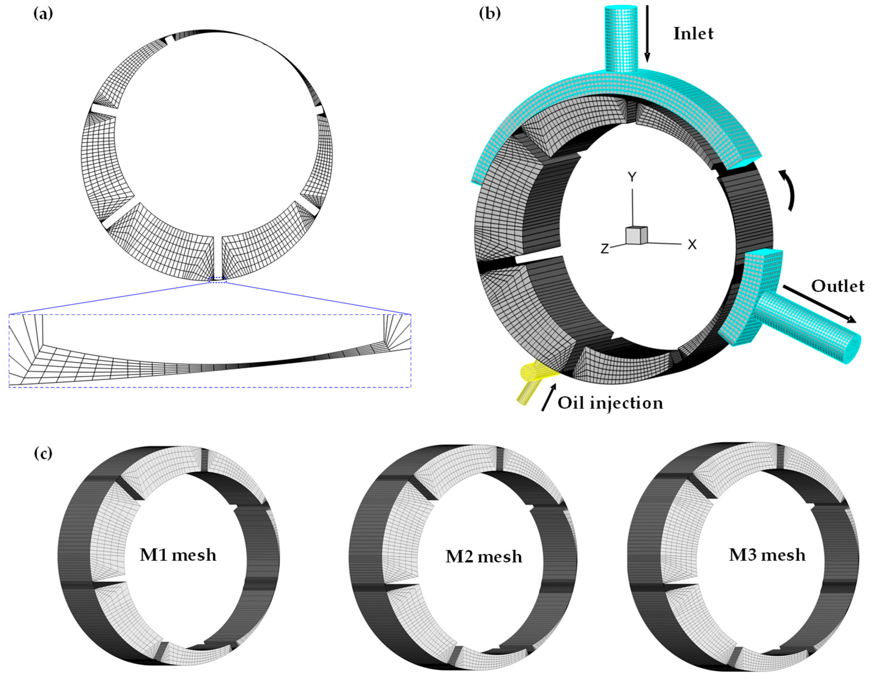
Grid generation of RVCs is a key step in performing CFD simulations due to the challenge of representing the moving and deforming rotor domain. A fully analytical grid generation method proposed in a previous study by the authors was utilised in this work. The detailed mesh generation method can be seen in ref. [37]. The computational domain is divided into the core region and the port region. The former is discretised through the aforementioned analytical grid generation approach, and the latter is treated using the traditional grid generation tools in the ANSYS software 18.0 suite. The resulting computational mesh is displayed in Figure 2. Figure 2a shows a two-dimensional rotor mesh with a local magnified view of vane tip clearance, while Figure 2b illustrates a three-dimensional mesh for rotor and port domains. Since the primary focus is on main flows instead of boundary layers, the present work does not take inflation layers into account, which also leads to a smaller mesh count and shorter computational time.

2.3. Assumptions

Several assumptions were utilised in CFD simulations to obtain better computational efficiency. In terms of fluid properties, air, as well as oil, is treated as Newtonian immiscible fluid, which means that no mass transfer occurs between air and oil. In addition, the air is modelled as ideal gas as the operating pressure remains within several bars. And the oil is a kind of incompressible and continuous fluid with fixed density, specific heat, dynamic viscosity and thermal conductivity. In reality, the inlet and outlet temperature values are about 25 °C and 65 °C, respectively. All the density, specific heat, dynamic viscosity and thermal conductivity of the oil slightly vary with the temperature from 25 to 65 °C. Therefore, the mentioned thermophysical properties at an average of 45 °C are employed for the present work. The physical and thermal properties of the air and oil phase are displayed in Table 2. Additionally, the constant clearance between the vane tip and the stator inner surface throughout a full revolution is assumed to further reduce the computational complexity. This is a trade-off between the actual operation circumstances and ideal geometrical tangency, with the vane tip sliding along a fluid film to prevent direct contact with the inner surface of the stator. Also, the heat transfer between the compressor body and working fluids is not considered in this work.

2.4. Multi-Phase Model

In the two-phase numerical simulations of the oil-injected RVCs in this work, the gas–liquid interface is captured by the Volume of Fluid (VOF) model. Since air and oil are immiscible fluids, the property, like density, can be governed by volume fractions:
ρ = α l ρ l + α g ρ g
α l + α g = 1
where ρ is density of mixed phase, ρ l is liquid destiny, ρ g is gas density, α l is liquid volume fraction, α g is gas volume fraction.
These variables are utilised in continuity, momentum and energy equations [38]:
ρ t + · ρ v = 0
t ρ v + · ρ v v = p + · μ v + v T + ρ G + F
t k = 1 n α l ρ l h l + · [ α l ( ρ l v l h l δ T ) ] = 0
t k = 1 n α g ρ g h g + · [ α g ( ρ g v g h g δ T ) ] = 0
where t is time, v is velocity of mixed phase, v l is liquid velocity, v g is gas velocity, μ is viscosity, F is body force, G is gravity term. h l is liquid enthalpy, h g is gas enthalpy, T is temperature.

2.5. Simulation Setup

All simulation cases in this work were conducted using the ANSYS FLUENT solver, with detailed solver settings provided in Table 3. The SST k-ω model is selected to characterise the turbulence condition. And the VOF method is utilised to capture the gas–liquid interface. The choice of using first order of accuracy in the numerical simulations is primarily due to better stability of simulations, especially due to the large deformation of the cells that is experienced in the rotor domain with large pressure and oil volume fraction gradients. In fact, the complexity of the oil–gas two-phase CFD simulations on Rotary Vane Compressors tends to lead to computational instability, while a high order of accuracy requires more computational cost for each angular simulation step. The convergence criteria for the energy equation is set to 10−6, and the convergence criteria for other equations is 10−3. The angular step size per time step is 0.25°, resulting in 1440 angular grid positions for a full revolution cycle. The reference operating conditions used as boundary conditions are outlined in Table 4. Regarding boundary conditions, constant values for pressure and temperature are applied to the intake port, while the exhaust port is defined with a constant pressure value. In terms of oil injection, oil is fed by a common rail and then injected into the working chambers by calibrated orifices positioned along the axial direction. Among the benchmark operating conditions, the rotational speed is 1000 RPM, the boundary condition of the oil injection is mass flow rate and the oil injection pressure, temperature and mass flow rate are 6.6 bar, 338.2 K and 0.11 kg/s, respectively.

2.6. Grid Independence Test

The reliability of the results has been verified by a grid independence investigation. The rotor mesh at three different refinements is shown in Figure 2c, while the port meshes remain unchanged. Table 5 shows the simulated results for three different sizes of rotor grids. The relative difference in the air-flow rate between M2 mesh and M3 mesh is close to 0.3%, while the corresponding difference in the shaft power is less than 0.3%. Therefore, taking both computational cost and simulation accuracy into consideration, a rotor mesh of 151,232 cells (M2 mesh) is used for all numerical simulations. In addition, all CFD cases use the same port mesh, as this does not impact air capacity and shaft power.

2.7. Method Validation

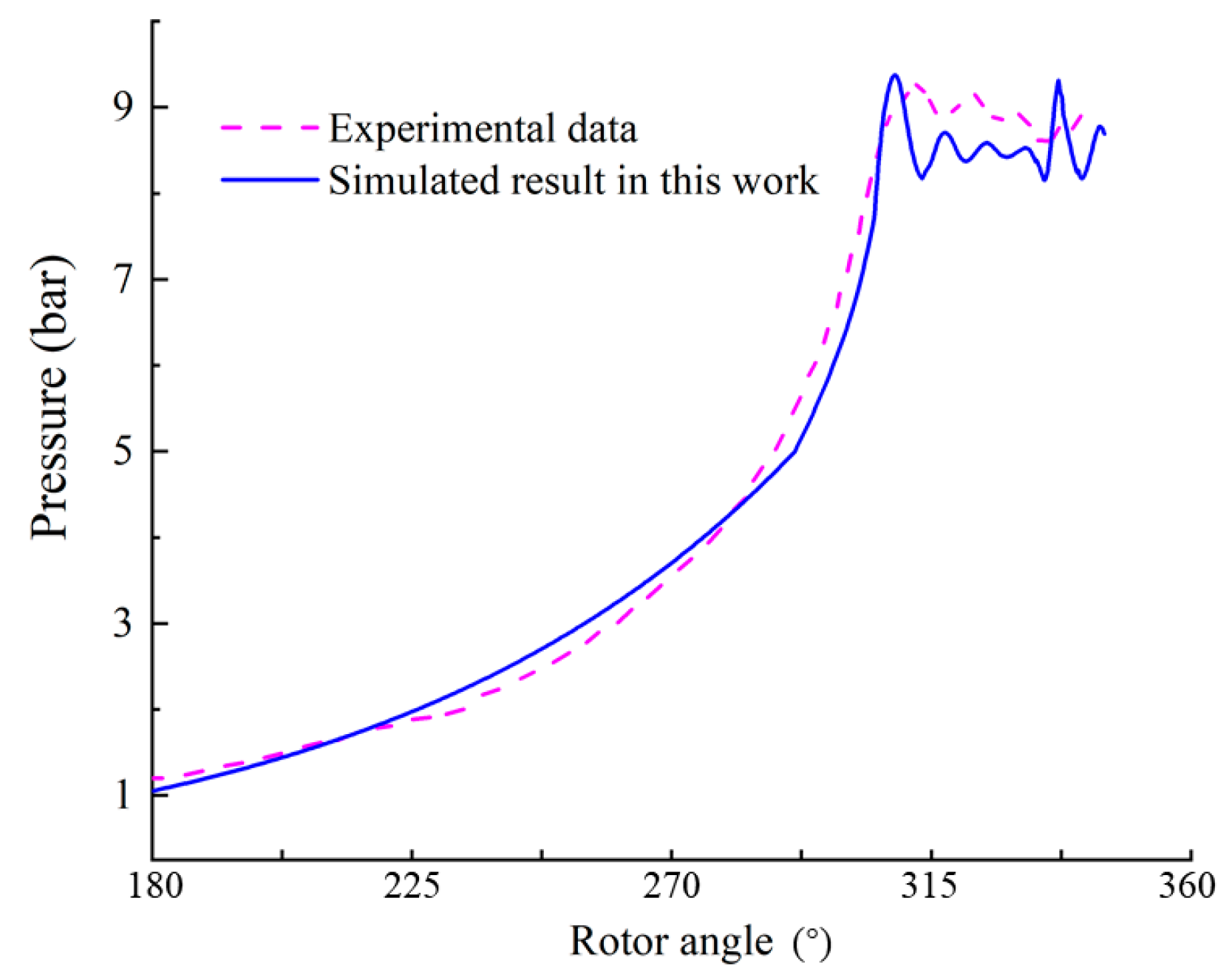
To validate the gas–liquid two-phase CFD model of the RVC established in this work, the obtained simulated data are compared to the corresponding experimental results [8]. Figure 3 shows the pressure trace varying with the rotor angle between the previous experimental test and the present simulation. As a result, the maximum difference between experimental and simulated pressure is less than 5.0% within the testing range. This difference may result from the simplification of no axial leakage clearance in the geometrical model. Consequently, the numerical method established in this work is considered credible to simulate the flow characteristics and the working performance of RVCs.

3. Oil Distribution and Comparison with Industrial Market Compressor

Internal flow is important for lubrication and sealing characteristics, which are reported in detail in ref. [34] for a baseline case (oil injection flow rate = 0.14 kg/s, oil injection angle = 228°). With the optimised oil injection flow rate of 0.11 kg/s and oil injection angle of 236°, this paper briefly reveals the oil distribution in Section 3.1. In Section 3.2, the volumetric and adiabatic efficiencies as well as specific power are then employed to characterise RVC performance followed by a comparison with the industrial market RVCs.

3.1. Oil Distribution Feature

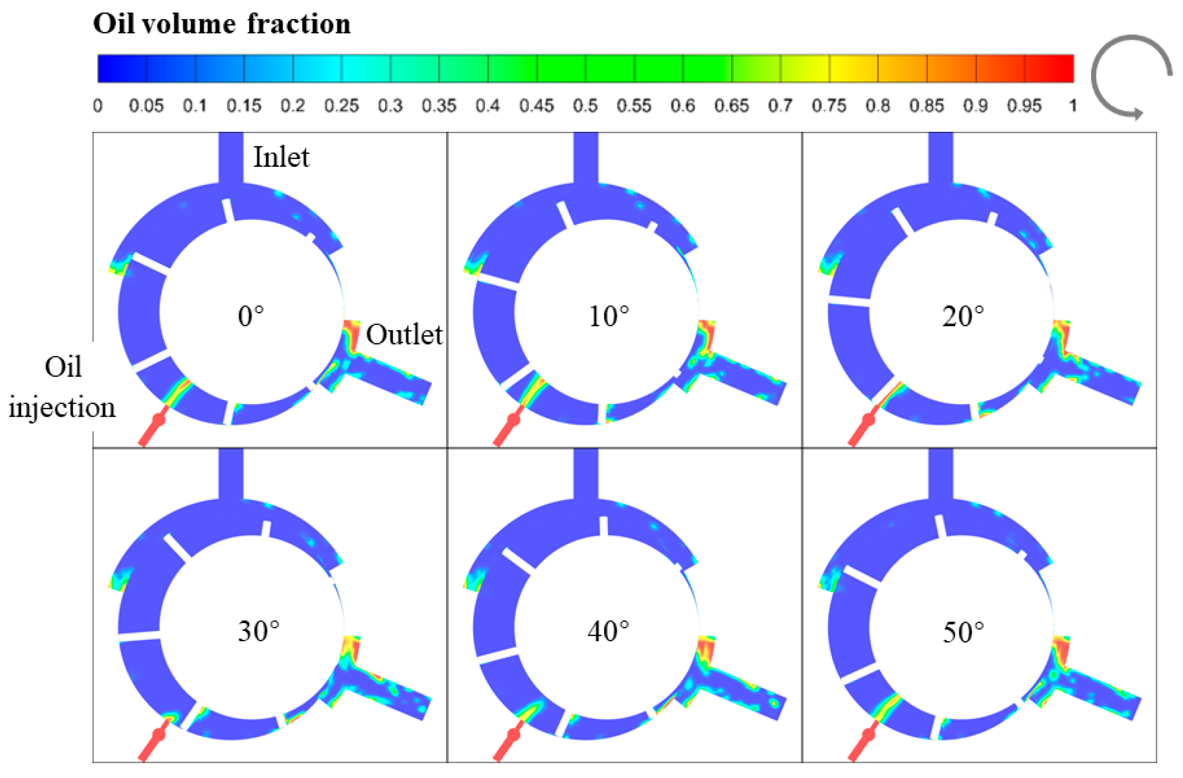
The oil distribution at mid-length of the RVC throughout a full cycle is illustrated in Figure 4. The oil is injected into the chambers radially at the rotor angle of 236°. The oil tends to spread along the leading edge of the vanes. Then, due to the high viscosity, the oil accumulates on the surface of the rotor outer wall, the stator inner wall and the vane side wall. The local oil accumulation blocks oil–gas mixing, thereby impacting the cooling performance. With the rotation of the rotor, the accumulated oil tends to flow into the vane tip gap, resulting in better sealing lubrication performance at the vane tip region. The narrow clearance at the vane tips restricts the oil entry when the vanes pass along the injection port, which causes a reduction in the flow rate of the oil, as observed at the rotor angle of 20° in Figure 4. During the exhaust stage, the mixing of oil and air becomes more uniform, resulting in sufficient air cooling. Ultimately, most oil exits through the exhaust port, and the rest leaks through the tangential gap to the next cycle.

3.2. Comparison with Industrial Market Compressor

In this work, the performance of the RVC is evaluated by volumetric and adiabatic efficiencies and specific power whose definitions are referenced in [34]. The RVC reference case obtains the volumetric and adiabatic efficiencies of 95.4% and 62.3%, respectively, and the specific power of 9.47 kW/(m3·min−1). A comparison of the compressor performance between this work and in industrial market technology is reported in detail in ref. [34] and briefly recalled here. The specific power against the compression ratio obtained in this work is compared to the one in existing technology [39], as shown in Figure 5. Both air-cooled RVCs in the market and oil-injected RVCs in the present study almost linearly increase with compression ratio. Nevertheless, the specific power in market compressors is lower than that obtained in this work. One reason for this result is the difference in cooling approaches. Oil-injected approach belongs to an internal-cooling category, while the air-cooled method is an external-cooling category. Also, an oil jet rather than an oil spray is utilised in the present study, which results in larger energy consumption. For both cooling approaches, the specific power almost increases linearly with the compression ratio. That is to say, the variation trend is the same, which ulteriorly validates the reliability of the simulated results.

4. Influences of Vane Parameters on RVC Performance

Within the same overall size of the machine, the structure parameters available for optimisation are the vane geometrical parameters. The effects of the vane parameters including vane tip clearance, vane tip radius, vane thickness, vane eccentric angle and vane tip eccentric angle on the RVC performance are investigated in this section.

4.1. Effects of Vane Tip Clearance

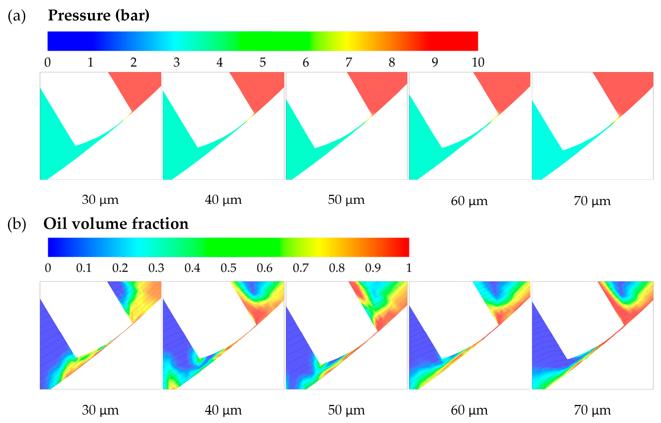
In the present work, the vane tip clearance ranges from 30 to 70 μm. Figure 6 shows the flow field at vane tip clearance with different clearance sizes and the impact of tip clearance on compressor performance. The vane tip leakage channel can be regarded as a nozzle. It can be seen from Figure 6a,b that the pressure gradient and oil volume fraction in the nozzle region are similar with different clearance sizes. Larger tip clearance leads to larger tip leakage and consequently lower volumetric efficiency, which is consistent with the result in Figure 6c. Also, larger leakage results in lower air capacity and, consequently, higher specific power. This is also consistent with the result shown in Figure 6c, that the specific power steadily increases with tip clearance from 30 to 70 μm. Specifically, the volumetric efficiency steadily reduces from 95.9% to 94.3% with the tip clearance from 30 to 70 μm. Similarly to volumetric efficiency, the adiabatic efficiency declines from 63.0% to 61.3% with the vane tip clearance from 30 to 70 μm. This is because larger clearance leads to lower adiabatic work due to the reduced seal effects. The specific power defined by the actual work to the air volumetric capacity improves from 9.36 to 9.61 kW/(m3·min−1) with the vane tip gap from 30 to 70 μm. Larger clearance leads to a worse seal effect and consequently decreases the air-flow rate, while larger tip leakage decreases the actual work at the same time. Considering the impacts of the tip clearance on both the air-flow rate and the actual work, the specific power increases steadily with the vane tip clearance. From the above analysis, the RVC as a high-efficiency compressor highly depends on the vane tip gap size. It would be significative to reduce the vane tip clearance through advanced technical methods.

4.2. Effects of Vane Thickness

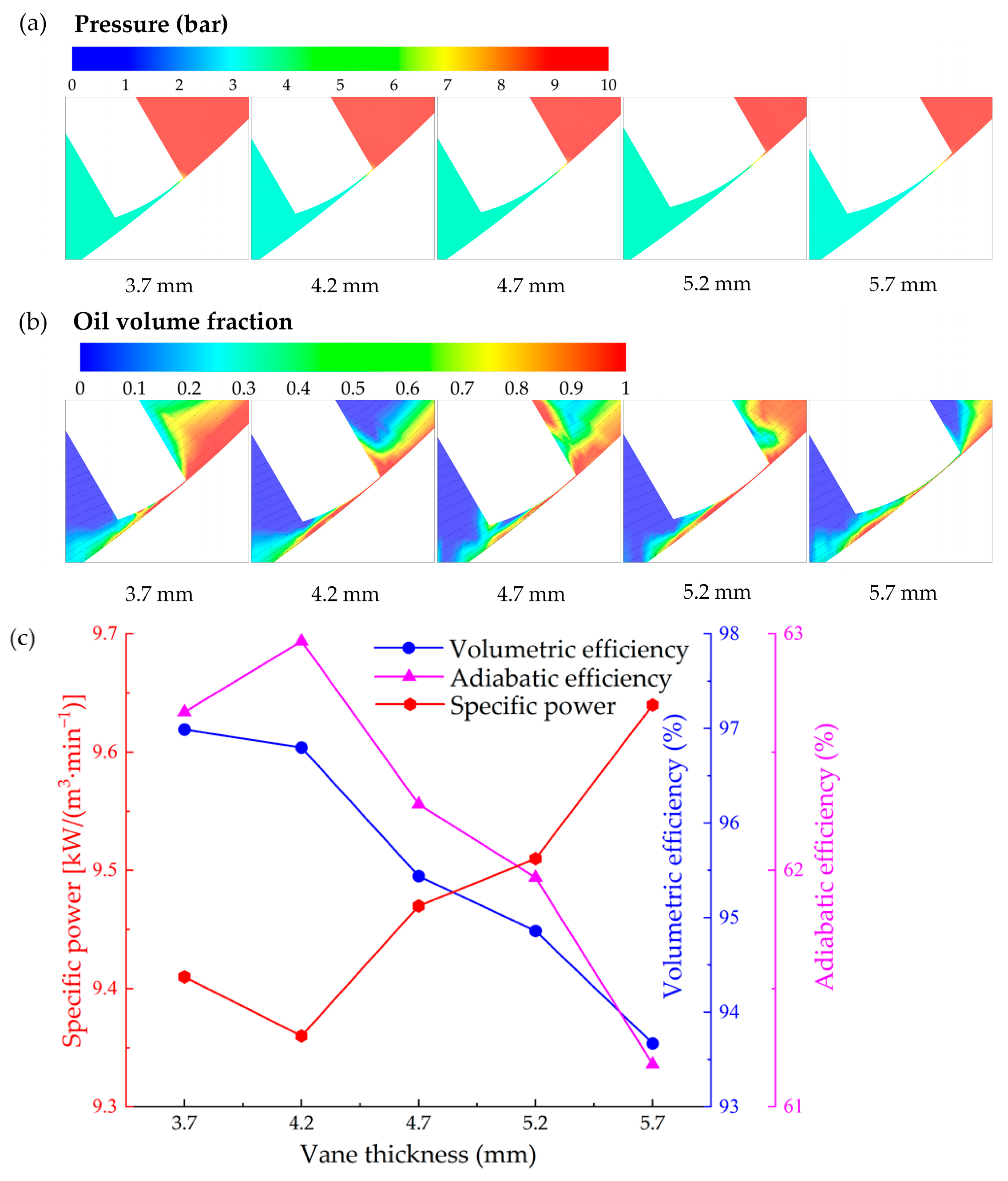
Despite the vane tip clearance size remaining unchanged at 50 μm, the vane thickness affects both the volume of the chambers and the length of the vane tip leakage channel. Figure 7 shows the flow field at vane tip clearance with different vane thicknesses and the impact of vane thickness on compressor performance. It can be seen from Figure 7a that thicker vanes result in a lower pressure gradient in the nozzle region, which helps to reduce leakage. As shown in Figure 7b, the oil volume fraction is relatively higher at 4.2 mm vane thickness, which may contribute to improving compressor performance. A larger vane thickness reduces the theoretical flow rate (due to the reduction in displacement volume of the chambers) and the simulated flow rate at the same time, leading to a steady decrease from 96.9% to 93.7% in the volumetric efficiency with the vane thickness from 3.7 to 5.7 mm, as illustrated in Figure 7c. A cumulative, yet counterflow effect is that a thin vane offers smaller resistance to leakage flow. Pressure diffusion and leakage are higher across thinner vanes compared to thicker vanes, which means that the vane tip leakage reduces with the vane thickness from 3.7 to 5.7 mm. An optimum vane thickness that balances, leakage with the reduction in geometrical chamber volume thus exists. As seen in the result of Figure 7c, the adiabatic efficiency wholly decreases from 62.9% to 61.2%. While the specific power decreases from 9.41 to 9.36 kW/(m3·min−1) with the vane thickness from 3.7 to 4.2 mm and increases to 9.64 kW/(m3·min−1) as the vane thickness further increases to 5.7 mm. The synthetic effect leads the specific power, defined as the ratio of the actual work to the capacity, to reach its lowest value of 9.36 kW/(m3·min−1) at the vane thickness of 4.2 mm. From the results, a vane thickness of 4.2 mm is recommended for the present RVC.

4.3. Effects of Vane Tip Radius

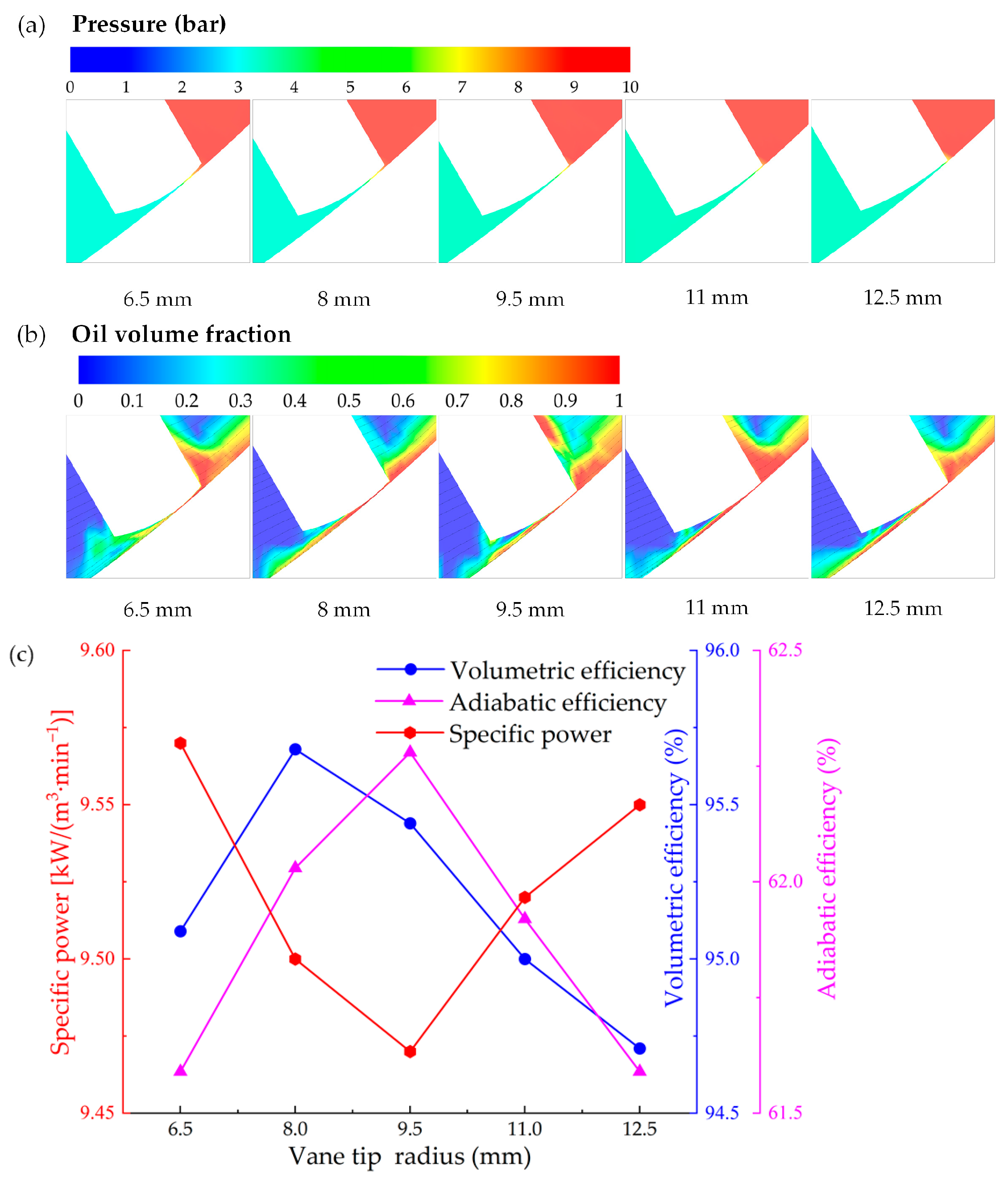
The minimum gap between the vane tip and the stator inner surface occurs just once with consideration of finite vane thickness. This causes the position at the vane tip profile corresponding to the minimum gap to change with the rotor rotation. In addition, the vane tip radius affects the shape of the vane tip gap. For instance, increasing the vane tip radius decreases the sizes of the inlet and the outlet of the vane tip leakage channel. As shown in Figure 8a, the pressure gradient in the nozzle region is relatively lower for vane tip radius = 8 mm, leading to smaller tip leakage and consequently higher volumetric efficiency, which is consistent in Figure 8c. In Figure 8b, the average oil volume fraction is relatively higher for vane tip radius = 9.5 mm, which contributes to achieving better performance of RVC. This is also consistent with the result shown in Figure 8c that the specific power reaches its bottom at the vane tip radius of 9.5 mm. Specifically, the volumetric efficiency increases with the vane tip radius from 6.5 to 8.0 mm and then decreases with the radius from 8.0 to 12.5 mm, reaching its peak of 95.7% at the radius of 8.0 mm. The variation trend of the adiabatic efficiency is similar to that of the volumetric efficiency, the former achieves the maximum value of 62.3% with a radius of 9.5 mm. The specific power declines initially and then increases with the radius from 6.5 to 12.5 mm, reaching its bottom of 9.47 kW/(m3·min−1) at a radius of 9.5 mm. Comprehensively taking into account the influences of the vane tip radius on the performance of the RVC, 9.5 mm is chosen for the vane tip radius.

4.4. Effects of Vane Eccentric Angle

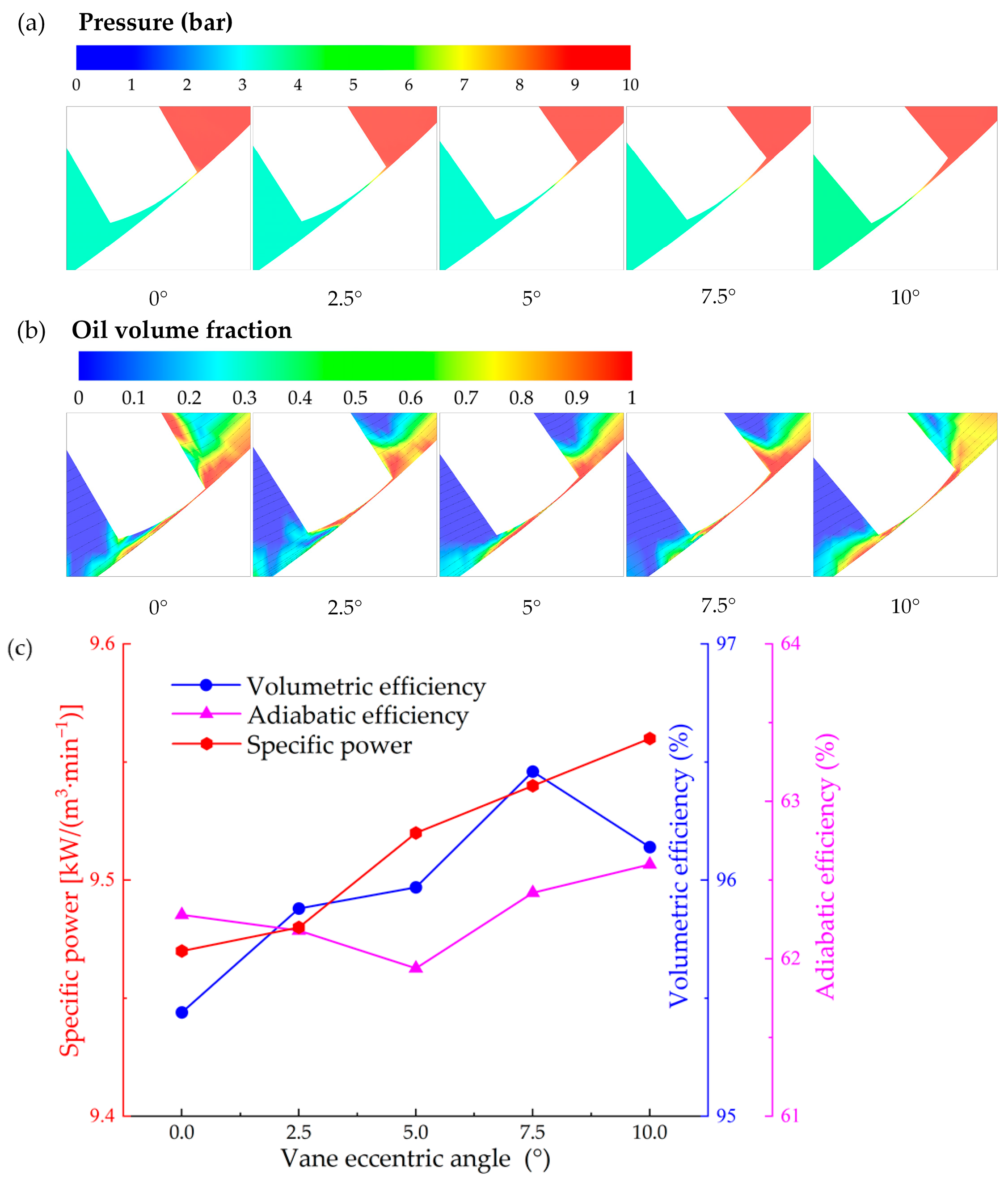
Figure 9 shows the flow field at vane tip clearance with different vane eccentric angles and the impact of vane eccentric angle on compressor performance. As shown in Figure 9a,b, the pressure gradient in the nozzle region is similar for different vane eccentric angles, while the average oil volume fraction in the nozzle region is relatively higher with a vane eccentric angle of 7.5°. This leads to relatively lower tip leakage and consequently higher volumetric efficiency for a 7.5° vane eccentric angle, as illustrated in Figure 9c. The vane eccentric angle influences the shape of the vane tip clearance gap. A larger vane eccentric angle leads to a larger inlet area and smaller outlet area of the vane tip clearance. As a result, with the vane eccentric angle from 0° to 10°, the adiabatic efficiency almost keeps constant, while the specific power steadily reduces from 9.47 to 9.56 kW/(m3·min−1), which has unfavourable effects on the energy consumption. From the above results, acting on the vane tilt produces an adverse influence, rather than improvement for the compressor performance. The vane-centred configuration is suggested for the RVC in this work.

4.5. Effects of Vane Tip Eccentric Angle

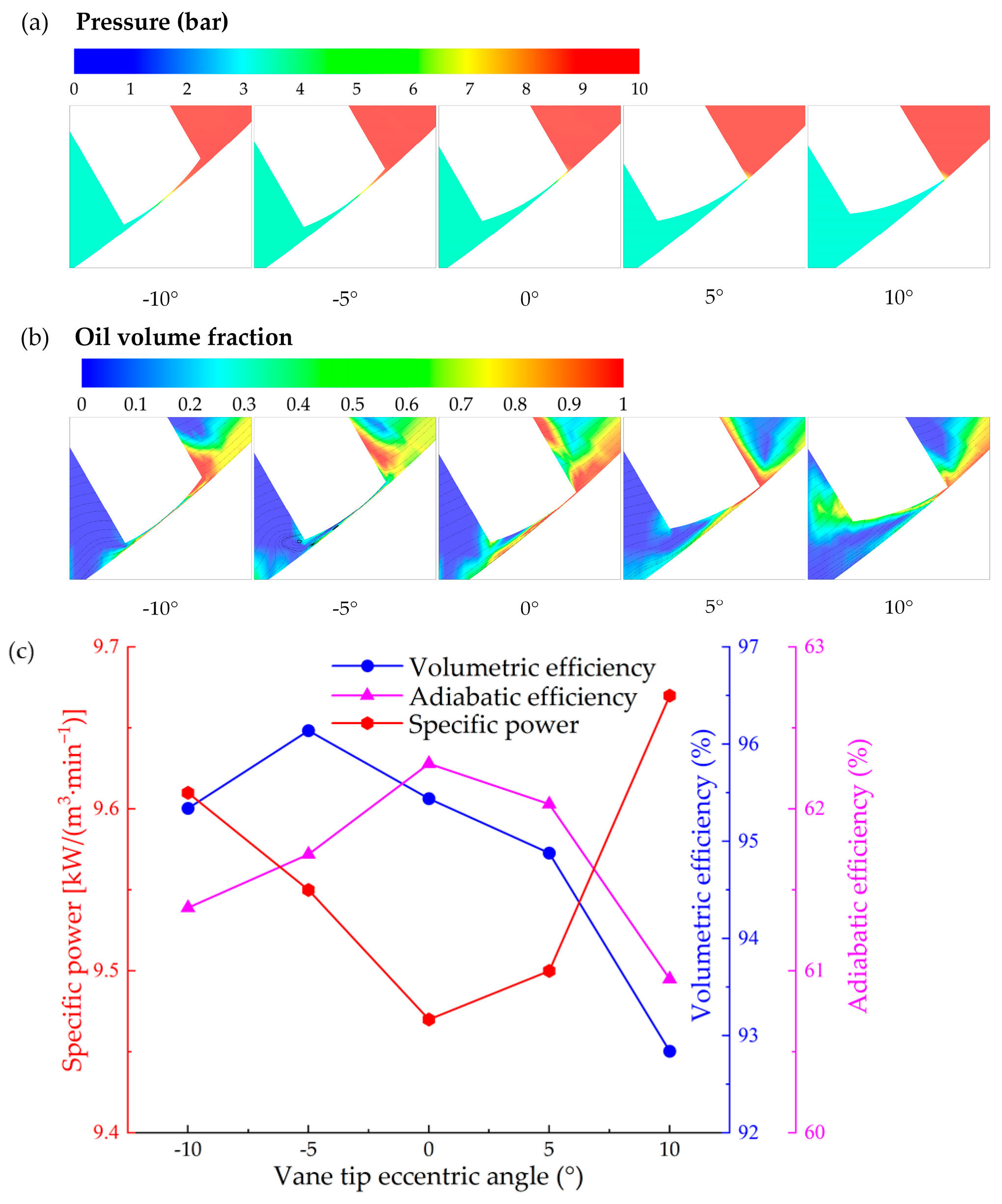
Similarly to the vane eccentric angle, a larger vane tip eccentric angle increases the inlet area and decreases the outlet area of the vane tip clearance. Figure 10 shows the flow field at vane tip clearance with different vane tip eccentric angles and the impact of vane tip eccentric angle on compressor performance. As shown in Figure 10a, the pressure gradient in the nozzle region is relatively lower for the vane tip eccentric angle = −5°, leading to smaller tip leakage and consequently higher volumetric efficiency, which is consistent with the result in Figure 10c. In Figure 10b, the average oil volume fraction is relatively higher for vane tip eccentric angle = 0°, which contributes to achieving better performance of RVC. This is also consistent with the result shown in Figure 10c, that the specific power reaches its bottom at the vane tip eccentric angle of 0°. Specifically, with the increase in the vane tip eccentric angle from −10° to 10°, both the volumetric and the adiabatic efficiencies increase first and then show a downward trend. The former reaches its peak value of 96.1% at the eccentric angle of −5°, while the latter achieves its maximum value of 62.3% at the eccentric angle of 0°. In terms of specific power, any vane tip eccentric angles lead to more energy consumption. The specific power achieves its bottom value of 9.47 kW/(m3·min−1) as the vane tip eccentric angle is equal to 0°. Based on the above analysis, although the vane tip-tilt configuration would lead to slight improvements in the volumetric and adiabatic efficiencies, but also results in adverse influences on the specific power. Therefore, a vane tip eccentric angle of 0° is recommended for the present RVC.

5. Effects of Port Parameters on Compressor Performance

Ports are vital components of the RVC and require optimal design. In this section, the effects of the intake/exhaust port closing angles on the performance of the RVC have been studied.

5.1. Effects of Intake Port Closing Angle (Intake Port Opening Angle = 30°)

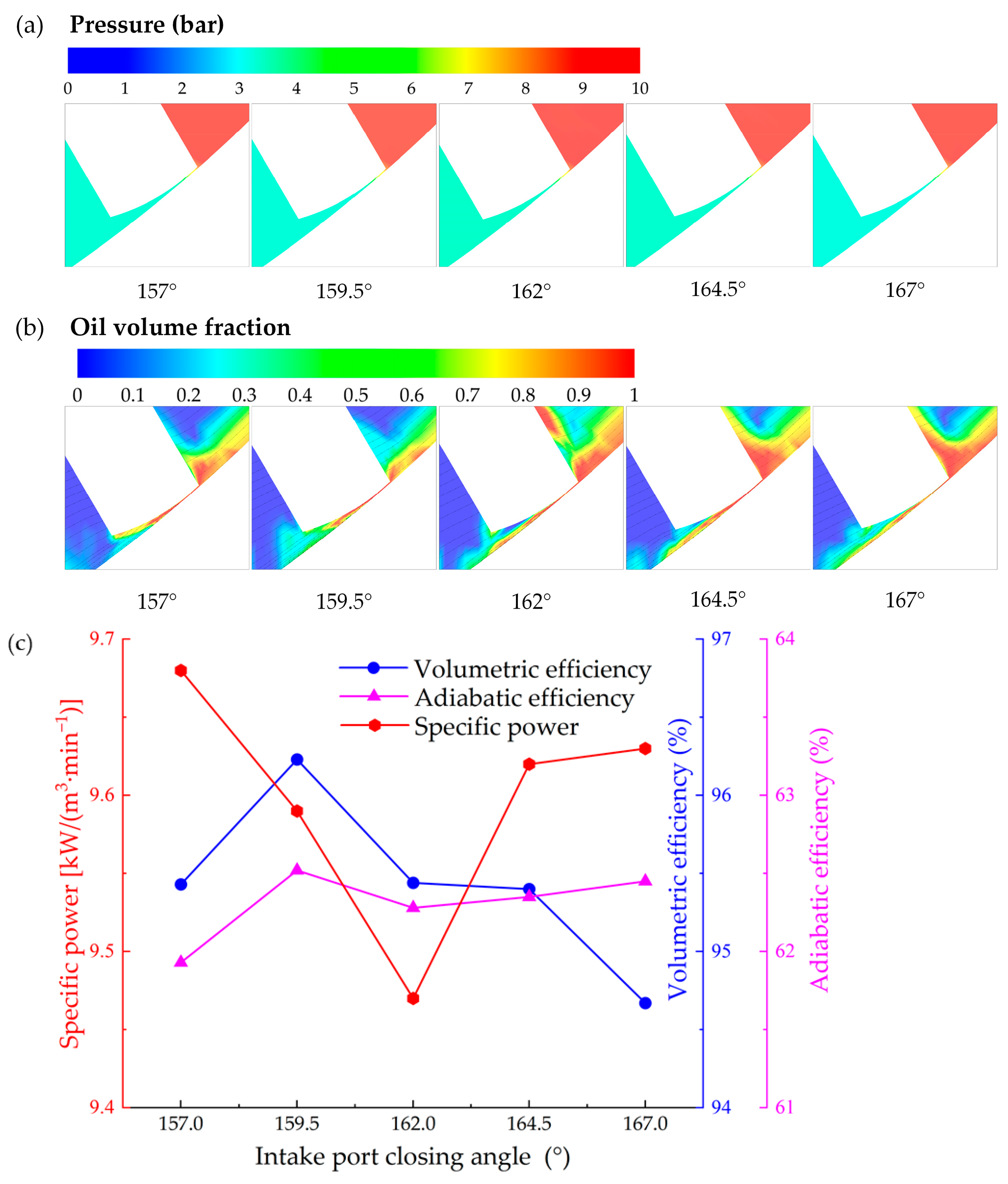
The intake port should be carefully designed, which needs to ensure an adequate intake process, as well as not affect the compression process. Figure 11 shows the flow field at vane tip clearance with different intake port closing angles and the impact of intake port closing angle on compressor performance with a fixed intake port opening angle of 30°. As shown in Figure 11a, the pressure gradient in the nozzle region is relatively lower for intake port closing angle = 159.5°, leading to smaller tip leakage and, consequently, higher volumetric efficiency, which is consistent with the result in Figure 11c. In Figure 11b, the average oil volume fraction is relatively higher for intake port closing angle = 162°, which contributes to achieving better performance of RVC. This is also consistent with the result shown in Figure 11c, that the specific power reaches its bottom at the intake port closing angle of 162.0°. The suction of air is more complete with an increase in the intake port closing angle due to the longer gas filling time, while the compression of the air may be not adequate due to the shorter gas compression time. As a consequence, the volumetric efficiency increases from 95.4% to 96.2% with the closing angle from 157.0° to 159.5° and decreases steadily from 96.2% to 94.6% with the closing angle from 159.5° to 167°. The adiabatic efficiency shows a slight increase with the closing angle from 157.0° to 159.5° and then almost remains constant with the closing angle from 159.5° to 167°. As the closing angle increases from 157.0° to 162°, the specific power obviously decreases from 9.68 to 9.47 kW/(m3·min−1) and then significantly increases to 9.63 kW/(m3·min−1), which also obtains its bottom at the angle of 162°. From the results, an intake port closing angle of 162° is suggested for the RVC if the intake port opening angle is fixed at 30°.

5.2. Effects of Intake Port Closing Angle (Intake Port Span Angle = 132°)

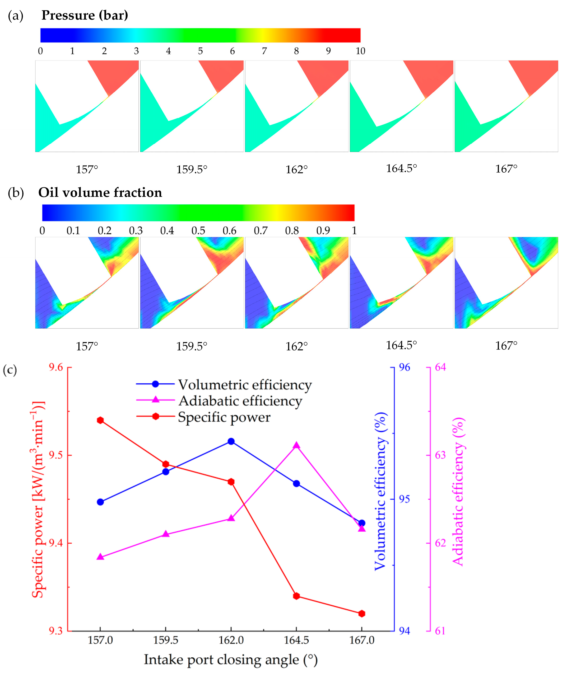
To ensure the adequate intake process of the air, a fixed intake span angle of 132° is controlled to study the influences of the intake port closing angle on the compressor performance. Figure 12 shows the flow field at vane tip clearance with different intake port closing angles and the impact of intake port closing angle on compressor performance. As shown in Figure 12a, the pressure gradient in the nozzle region is relatively lower for the intake port closing angle = 162°, leading to lower tip leakage and, consequently, higher volumetric efficiency, which is consistent with the result in Figure 12c. In Figure 12b, the average oil volume fraction is relatively higher for intake port closing angle = 167°, which contributes to achieving better performance of RVC. This is also consistent with the result shown in Figure 12c, that the specific power reaches its bottom at the intake port closing angle of 167°. Specifically, both the volumetric and adiabatic efficiencies increase initially and then decline with the closing angle from 157° to 167°. The former reaches its peak of 95.4% at the angle of 162.0°, while the latter obtains its maximum of 63.1% at the angle of 164.5°. The specific power shows a steady downward trend within the range of closing angle, reaching its minimum value of 9.32 kW/(m3·min−1) at the angle of 167°. Comparing the two schemes studied in Section 5.1 and Section 5.2, the latter achieves a more satisfactory result. With a fixed intake port span angle of 132°, about a 5.0° shift in the intake port closing angle leads to a 1.6% decrease in specific power. An intake port closing angle of 167° with a fixed intake port span angle of 132° is suggested for intake port optimisation.

5.3. Effects of Exhaust Port Closing Angle (Exhaust Port Opening Angle = 325°)

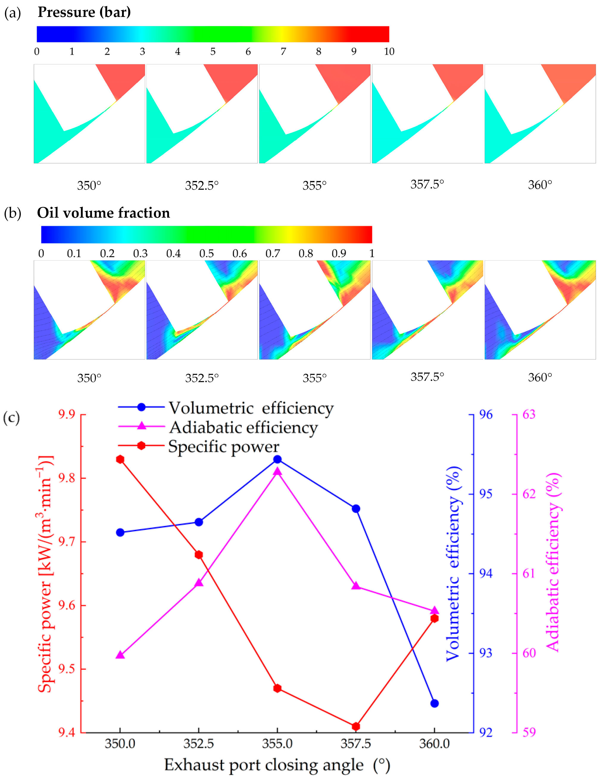
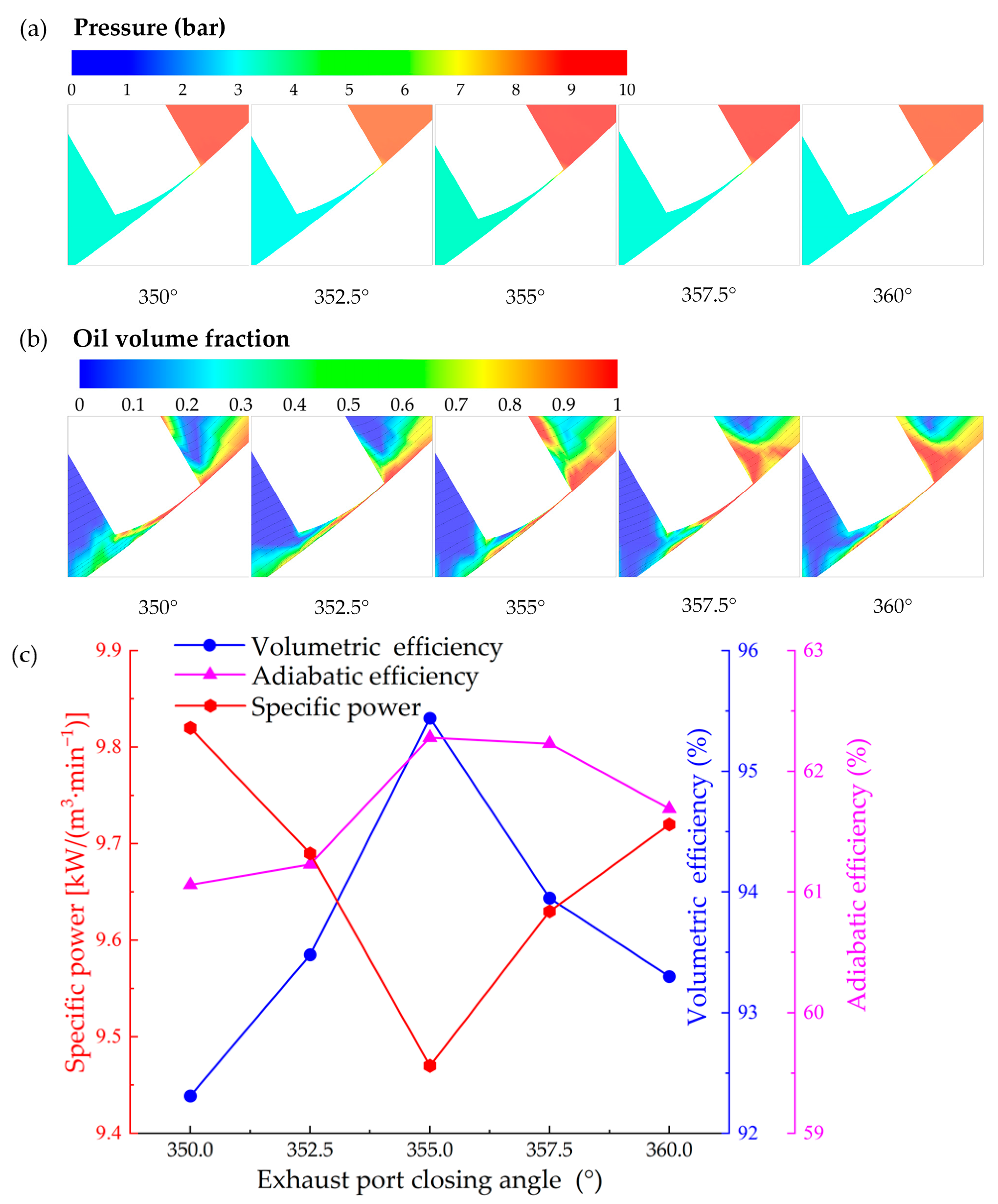
The exhaust port affects the compressor and exhaust process as well as the tangential leakage, which also should be precisely designed. Figure 13 shows the flow field at vane tip clearance with different exhaust port closing angles and the impact of exhaust port closing angle on compressor performance with a fixed exhaust port opening angle of 325°. As shown in Figure 13a, the pressure gradient in the nozzle region is relatively lower for the exhaust port closing angle = 355°, leading to smaller tip leakage and, consequently, higher volumetric efficiency, which is consistent with the result in Figure 13c. In Figure 13b, the average oil volume fraction is relatively higher for the exhaust port closing angle = 357.5°, which contributes to achieving better performance of RVC. This is also consistent with the result shown in Figure 13c that the specific power reaches its bottom at the exhaust port closing angle of 357.5°. With a fixed exhaust port opening angle of 325°, a too-small closing angle of the exhaust port would result in an incomplete exhaust phenomenon, while a too-large closing angle would lead to shorter tangential sealing length and consequently larger tangential leakage. As a consequence, both the volumetric and the adiabatic efficiencies increase with the closing angle from 350° to 355° and then decrease with the closing angle from 355° to 360°, obtaining the peak values of 95.4% and 62.3%, respectively, at the closing angle of 355°. The specific power sharply drops with the closing angle from 350.0° to 357.5° and then obviously increases with the closing angle from 357.5° to 360°, achieving its minimum value of 9.41 kW/(m3·min−1) at the closing angle of 357.5°. Therefore, an exhaust port closing angle of 357.5° is recommended with a fixed exhaust port opening angle of 325°.

5.4. Effects of Exhaust Port Closing Angle (Exhaust Port Span Angle = 30°)

To ensure the adequate exhaust process of the air, a fixed exhaust port span angle of 30° is controlled to study the impacts of the exhaust port closing angle on the compressor performance. Figure 14 shows the flow field at vane tip clearance with different exhaust port closing angles and the impact of exhaust port closing angle on compressor performance. As shown in Figure 14a, the pressure gradient in the nozzle region is relatively lower for the exhaust port closing angle = 355°, leading to smaller tip leakage and consequently higher volumetric efficiency, which is consistent with the result in Figure 14c. In Figure 14b, the average oil volume fraction is relatively higher for exhaust port closing angle = 355°, which contributes to achieving better performance of RVC. This is also consistent with the result shown in Figure 14c that the specific power reaches its bottom at the exhaust port closing angle of 355°. It should be noted that a larger exhaust port closing angle would lead to larger tangential leakage. As a consequence, both the volumetric and adiabatic efficiencies increase with the closing angle from 350° to 355° and then decrease with the closing angle from 355° to 360°, achieving peak values of 95.4% and 62.3%, respectively, at the closing angle of 355°. The specific power decreases sharply from 9.82 to 9.47 kW/(m3·min−1) with the closing angle from 350° to 355° and then increases obviously from 9.47 kW/(m3·min−1) to 9.72 kW/(m3·min−1) with the closing angle from 355° to 360°, reaching its bottom value of 9.47 kW/(m3·min−1) at the closing angle of 355°. Comparing the two schemes studied in Section 5.3 and Section 5.4, the former achieves a more satisfactory result. Around 2.5° expansion in the exhaust port span angle leads to a 0.6% decrease in specific power. Therefore, an exhaust port closing angle of 357.5° with a fixed exhaust port opening angle of 325° is suggested for exhaust port optimisation.
Table 6 summarises the optimisation outcomes of the vane parameters and the port timing angles, indicating that the structural optimisation contributes to enhancing the performance of the RVC with the same vane tip clearance of 50 μm. Specifically, the volumetric efficiency increased from 95.44% to 96.52%, resulting in a 1.1% improvement. The adiabatic efficiency improves from 62.28% to 63.07% with a slight increase of 0.8%. While the specific power decreases from 9.47 to 9.31 kW/(m3·min⁻1), resulting in a 1.7% reduction in energy consumption. On the whole, the optimisation results are not quite obvious, which also shows that our baseline structural parameters in terms of the vane geometry and port timing angles are reasonable. Altogether, the structural parameter optimisation carried out in this paper, combined with the operational parameter optimisation conducted in [34], leads to a power reduction of 5.6%.

6. Conclusions

This work performed an oil–gas two-phase CFD study on an oil-injected Rotary Vane Compressor (RVC). After the oil distribution feature has been characterised, the impact of structural parameters related to the vane geometry and intake/exhaust port closing angles on the performance of the RVC has been investigated. According to the simulated results, the oil tends to accumulate at the leading edge of the vane before flowing into the vane tip gap, leading to smaller leakage and sufficient lubrication at the vane tip. In terms of the RVC reference case, the compressor performance is evaluated by the volumetric efficiency of 95.4%, the adiabatic efficiency of 62.3% and the specific power is 9.47 kW/(m3·min⁻1). The RVC as a high-efficiency compressor highly relies on the vane tip clearance size. It can be concluded that with the changes in the dimensions, the results can be more reasonably generalised to other RVCs by the normalised tip clearance (ratio of tip clearance to rotor radius), rather than the tip clearance. The appropriate values of the vane thickness and vane tip radius help to reduce specific power, while the vane tilt arrangement and the vane tip eccentric configuration have adverse influences on the compressor performance in the present study. Considering the effects on the overall compressor performance, the optimised values for vane thickness, vane tip radius, vane eccentric angle and vane tip eccentric angle are 4.2 mm, 9.5 mm, 0° and 0°, respectively. Optimisation of the intake/exhaust port closing angles helps to improve the compressor performance. With a constant intake port span angle of 132°, about a 5.0° shift in the intake port closing angle helps to decrease the specific power by 1.6%. In addition, with a fixed exhaust port opening angle of 325°, around 2.5° expansion in the exhaust port span angle leads to a 0.6% decrease in the specific power. The optimisation results show that the baseline parameters of the vane geometry and the port timing angle are relatively reasonable. Comprehensive optimisation leads to a further 1.1% increase in the volumetric efficiency, a further 0.8% increase in the adiabatic efficiency and a further 1.7% decrease in the specific power. Overall, the structural parameter optimisation carried out in this paper, combined with the operational parameter optimisation conducted in previous studies, led to a power reduction of 5.6%.

Author Contributions

Conceptualisations, F.Y. and H.Z.; methodology, F.Y., H.Z. and S.R.; software, F.Y., H.Z. and S.R.; formal analysis, F.Y., H.Z., Y.P., G.B., S.R. and Y.D.; writing—original draft preparation, F.Y., H.Z., Y.P. and Y.D.; writing—review and edition, F.Y., G.B. and S.R.; visualisation, H.Z. and Y.P.; supervision, F.Y., G.B. and S.R.; project administration, S.R.; funding acquisition, F.Y. All authors have read and agreed to the published version of the manuscript.

Funding

This research was funded by the Jiangxi Provincial Natural Science Foundation, grant number 20242BAB20213.

Data Availability Statement

The raw data supporting the conclusions of this article will be made available by the authors upon request.

Conflicts of Interest

The authors declare no conflicts of interest.

Nomenclature and Abbreviations

The following symbols and abbreviations are used in this manuscript:
αVolume fraction [-]
βEccentric angle [°]
γSpecific heat ratio [-]
ηEfficiency [-]
μDynamic viscosity [Pa·s]
ρDensity [kg/m3]
τTorque [Nm]
λThermal conductivity [W/(m·k)]
cpSpecific heat capacity [J/(kg·K)]
CClearance [µm]
eEccentricity distance [mm]
FBody force [-]
gGas phase [-]
GGravity term [-]
hSpecific enthalpy [J/mol]
lLiquid phase [-]
mMass flow rate [kg/s]
nRotational speed [RPM]
pPressure [bar]
QVolume flow rate [m3/min]
RRadius [mm]
tTime [s]
TTemperature [K]
ThThickness [mm]
vVelocity [m/s]
WPower [W]
ZAxial length [mm]
axiAxial
gapTangential clearance
rotRotor
staStator
tipVane tip
vaneVane
CFDComputational Fluid Dynamics
RVCRotary Vane Compressor
VOFVolume of Fluid

References

  1. Aw, K.T.; Ooi, K.T. A review on sliding vane and rolling piston compressors. Machines 2021, 9, 125. [Google Scholar] [CrossRef]
  2. Liu, S.; Ma, G.; Xu, S.; Gong, Y.; Jia, X.; Wu, G. A review of reverse Brayton air cycle refrigerators. Int. J. Refrig. 2023, 150, 200–214. [Google Scholar] [CrossRef]
  3. Wang, C.; Wu, J.; Du, Y.; Lei, B. Lubricating condition evaluation of the rotary compressor under high ambient temperature. Int. J. Refrig. 2020, 118, 220–229. [Google Scholar] [CrossRef]
  4. Hosseinnia, S.M.; Amiri, L.; Poncet, S. Performance analysis of a novel air source ammonia/water cascade heat pump for heating buildings in subarctic climate. Int. J. Refrig. 2024, 164, 57–74. [Google Scholar] [CrossRef]
  5. Olympios, A.V.; Song, J.; Ziolkowski, A.; Shanmugam, V.S.; Markides, C.N. Data-driven compressor performance maps and cost correlations for small-scale heat-pumping applications. Energy 2024, 291, 130171. [Google Scholar] [CrossRef]
  6. Valenti, G.; Murgia, S.; Contaldi, G.; Valenti, A. Experimental evidence of the thermal effect of lubricating oil sprayed in sliding-vane air compressors. Case Stud. Therm. Eng. 2014, 4, 113–117. [Google Scholar] [CrossRef]
  7. Vittorini, D.; Cipollone, R. Financial analysis of energy saving via compressor replacement in industry. Energy 2016, 113, 809–820. [Google Scholar] [CrossRef]
  8. Bianchi, G.; Cipollone, R.; Murgia, S.; Contaldi, G. Development of an internal air cooling sprayed oil injection technique for the energy saving in sliding vane rotary compressors through theoretical and experimental methodologies. Int. J. Refrig. 2015, 52, 11–20. [Google Scholar] [CrossRef]
  9. Vittorini, D.; Cipollone, R. Energy saving potential in existing industrial compressors. Energy 2016, 102, 502–515. [Google Scholar] [CrossRef]
  10. Choo, W.C.; Ooi, K.T. Analysis of the novel multi-vane Revolving Vane compressor–Investigation of vane chattering phenomenon through instantaneous working chamber pressure measurements. Int. J. Refrig. 2022, 134, 207–218. [Google Scholar] [CrossRef]
  11. Yang, B.; Peng, X.; Sun, S.; Guo, B.; Xing, Z. Study of a rotary vane expander for the transcritical CO2 cycle—Part I: Experimental investigation. HVAC&R Res. 2009, 15, 673–688. [Google Scholar] [CrossRef]
  12. Jia, X.; Zhang, B.; Pu, L.; Guo, B.; Peng, X. Improved rotary vane expander for trans-critical CO2 cycle by introducing high-pressure gas into the vane slots. Int. J. Refrig. 2011, 34, 732–741. [Google Scholar] [CrossRef]
  13. Fatigati, F.; Di Battista, D.; Cipollone, R. Design improvement of volumetric pump for engine cooling in the transportation sector. Energy 2021, 231, 120936. [Google Scholar] [CrossRef]
  14. Fatigati, F.; Bartolomeo, M.D.; Battista, D.D.; Cipollone, R. A dual-intake-port technology as a design option for a sliding vane rotary expander of small-scale ORC-based power units. Energy Convers. Manag. 2020, 209, 112646. [Google Scholar] [CrossRef]
  15. Natali, C.; Battarra, M.; Proner, E.; Mucchi, E. Advantages of elliptical tip vanes on the kinematic design of balanced vane pumps. Mech. Mach. Theory 2025, 206, 105901. [Google Scholar] [CrossRef]
  16. Chen, Z.; Wang, J.; Cui, S.; Feng, H.; Sha, R. Numerical simulation and design methodology of a novel asymmetric cylinder profile for sliding vane vacuum pumps. Vacuum 2019, 169, 108945. [Google Scholar] [CrossRef]
  17. Wang, J.; Chen, Z.; Yang, S.; Li, H.; Cui, S. Geometric design and analysis of a novel sliding vane vacuum pump with three chambers. Mech. Mach. Theory 2019, 141, 52–66. [Google Scholar] [CrossRef]
  18. Choo, W.C.; Ooi, K.T. Analysis of the novel multi-vane Revolving Vane compressor–Theoretical modelling and experimental investigations. Int. J. Refrig. 2021, 131, 592–603. [Google Scholar] [CrossRef]
  19. Zhou, H.; Qu, Z.; Yang, H.; Yu, B. Dynamic model and numerical simulation for synchronal rotary compressor. ASME J. Fluids Eng. 2009, 131, 041102. [Google Scholar] [CrossRef]
  20. Wang, M.; Zhao, Y.; Cao, F.; Bu, G.; Wang, Z. Simulation study on a novel vane-type expander with internal two-stage expansion process for R-410A refrigeration system. Int. J. Refrig. 2012, 35, 757–771. [Google Scholar] [CrossRef]
  21. Gu, H.; Zhou, X.; Chen, Y.; Wu, J.; Wu, Z.; Jiang, Y.; Sund’en, B. Analysis, modeling and simulations of an innovative sliding vane rotary compressor with a rotating cylinder. Energy Convers. Manag. 2021, 230, 113822. [Google Scholar] [CrossRef]
  22. Shakya, P.; Ooi, K.T. Introduction to Coupled Vane compressor: Mathematical modelling with validation. Int. J. Refrig. 2020, 117, 23–32. [Google Scholar] [CrossRef]
  23. Bradshaw, C.R.; Groll, E.A. A comprehensive model of a novel rotating spool compressor. Int. J. Refrig. 2013, 36, 1974–1981. [Google Scholar] [CrossRef]
  24. Prasad, B.G.S. CFD for positive displacement compressors. In Proceedings of the International Compressor Engineering Conference at Purdue University, West-Lafayette, IN, USA, 15–18 July 2004; Available online: https://docs.lib.purdue.edu/icec/1689/ (accessed on 21 May 2025).
  25. Hieronymus, T.; Lobsinger, T.; Brenner, G. A combined CFD-FEM approach to predict fluid-borne vibrations and noise radiation of a rotary vane pump. Energies 2021, 14, 1874. [Google Scholar] [CrossRef]
  26. Murthy, A.A.; Krishan, G.; Shenoy, P.; Patil, I.S. Theoretical, CFD modelling and experimental investigation of a four-intersecting-vane rotary expander. Appl. Energy 2024, 353, 122145. [Google Scholar] [CrossRef]
  27. Rak, J.; Błasiak, P.; Kolasiński, P. Influence of the applied working fluid and the arrangement of the steering edges on multi-vane expander performance in micro ORC system. Energies 2018, 11, 892. [Google Scholar] [CrossRef]
  28. Wang, J.; Liu, Y.; Chen, Z.; Tan, Q. Geometric model and pressurization analysis on a novel sliding vane compressor with an asymmetrical cylinder profile. Int. J. Refrig. 2021, 129, 175–183. [Google Scholar] [CrossRef]
  29. Błasiak, P.; Kolasiński, P.; Daniarta, S. Numerical analysis of heat transfer within a rotary multi-vane expander. Energies 2023, 16, 2794. [Google Scholar] [CrossRef]
  30. Montenegro, G.; Torre, A.D.; Fiocco, M.; Onorati, A.; Benatzky, C.; Schlager, G. Evaluating the performance of a rotary vane expander for small scale organic rankine cycles using CFD tools. Energy Procedia 2014, 45, 1136–1145. [Google Scholar] [CrossRef]
  31. Gu, H.; Chen, Y.; Wu, J.; Jiang, Y.; Sundén, B. Impact of discharge port configurations on the performance of sliding vane rotary compressors with a rotating cylinder. Appl. Therm. Eng. 2021, 186, 116526. [Google Scholar] [CrossRef]
  32. Gu, H.; Chen, Y.; Wu, J.; Sundén, B. Novel rotary sliding vane expanders with small eccentricity and guide vane ports: Numerical simulation and structural parameter analysis. Appl. Therm. Eng. 2024, 254, 123820. [Google Scholar] [CrossRef]
  33. Bianchi, G.; Rane, S.; Kovacevic, A.; Cipollone, R.; Murgia, S. Development of a general numerical methodology for CFD analyses in sliding vane machines and application on a mid-size oil injected air compressor. In Proceedings of the International Compressor Engineering Conference, West Lafayette, IN, USA, 11–14 July 2016; Available online: https://bura.brunel.ac.uk/handle/2438/14651 (accessed on 21 May 2025).
  34. Dai, Y.; Zhu, H.; Bianchi, G.; Rane, S.; Ye, F. Numerical investigation on flow characteristics and working performance in oil-injected sliding vane rotary compressors. Int. J. Refrig. 2025, 171, 202–216. [Google Scholar] [CrossRef]
  35. Zhang, Q.; Xu, X. Numerical simulation on cavitation in a vane pump with moving mesh. In Proceedings of the 5th International Conference on Computational Methods, Cambridge, UK, 28–30 July 2014; Available online: https://www.sci-en-tech.com/ICCM2014/PDFs/401-835-1-PB.pdf (accessed on 21 May 2025).
  36. Lobsinger, T.; Hieronymus, T.; Brenner, G. A CFD investigation of a 2D balanced vane pump focusing on leakage flows and multiphase flow characteristics. Energies 2020, 13, 3314. [Google Scholar] [CrossRef]
  37. Ye, F.; Bianchi, G.; Rane, S.; Tassou, S.A.; Deng, J. Analytical grid generation and numerical assessment of tip leakage flows in sliding vane rotary machines. Adv. Eng. Software 2021, 159, 103030. [Google Scholar] [CrossRef]
  38. ANSYS. ANSYS Fluent Theory Guide-Release 18.0; Ansys Inc.: Washington, PA, USA, 2017. [Google Scholar]
  39. Vittorini, D.; Bianchi, G.; Cipollone, R. Energy Saving Potential in Existing Volumetric Rotary Compressors. Energy Procedia 2015, 81, 1121–1130. [Google Scholar] [CrossRef]
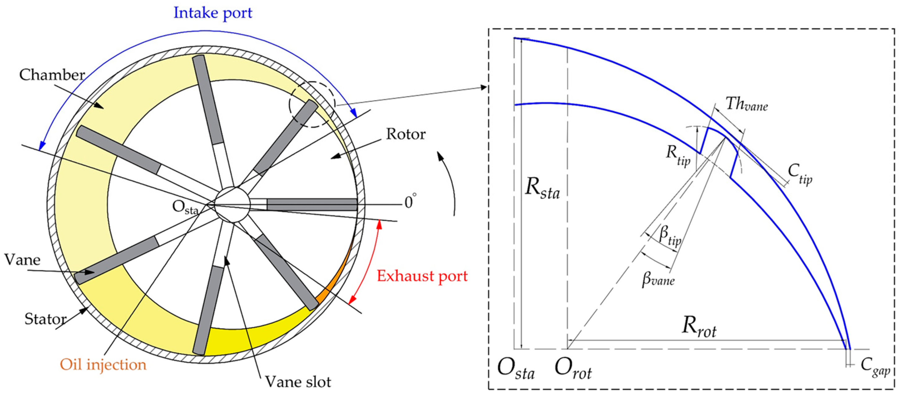
Figure 1. Schematic of RVC with port position.
Machines 13 00456 g001
Figure 2. Computational mesh: (a) two-dimensional rotor mesh with a local magnified view of vane tip clearance; (b) three-dimensional mesh for rotor and port domains; (c) different three-dimensional rotor mesh for grid independent test.
Machines 13 00456 g002
Figure 3. Cell pressure trace in simulated data and experimental results [8].
Machines 13 00456 g003
Figure 4. Oil volume fraction varying with rotor angle.
Machines 13 00456 g004
Figure 5. Specific power varying with compression ratio [34].
Machines 13 00456 g005
Figure 6. Effect of vane tip clearance on compressor performance: pressure field at vane tip gap (a), oil distribution at vane tip gap (b) and impact on specific power, adiabatic and volumetric efficiencies (c).
Machines 13 00456 g006aMachines 13 00456 g006b
Figure 7. Effect of vane thickness on compressor performance: pressure field at vane tip gap (a), oil distribution at vane tip gap (b) and impact on specific power, adiabatic and volumetric efficiencies (c).
Machines 13 00456 g007
Figure 8. Effect of vane tip radius on compressor performance: pressure field at vane tip gap (a), oil distribution at vane tip gap (b) and impact on specific power, adiabatic and volumetric efficiencies (c).
Machines 13 00456 g008
Figure 9. Effect of vane eccentric angle on compressor performance: pressure field at vane tip gap (a), oil distribution at vane tip gap (b) and impact on specific power, adiabatic and volumetric efficiencies (c).
Machines 13 00456 g009
Figure 10. Effect of vane tip eccentric angle on compressor performance: pressure field at vane tip gap (a), oil distribution at vane tip gap (b) and impact on specific power, adiabatic and volumetric efficiencies (c).
Machines 13 00456 g010
Figure 11. Effect of intake port closing angle on compressor performance: pressure field at vane tip gap (a), oil distribution at vane tip gap (b) and impact on specific power, adiabatic and volumetric efficiencies (c). Note that intake port opening angle = 30°.
Machines 13 00456 g011
Figure 12. Effect of intake port closing angle on compressor performance: pressure field at vane tip gap (a), oil distribution at vane tip gap (b) and impact on specific power, adiabatic and volumetric efficiencies (c). Note that intake port span angle = 132°.
Machines 13 00456 g012
Figure 13. Effect of exhaust port closing angle on compressor performance: pressure field at vane tip gap (a), oil distribution at vane tip gap (b) and impact on specific power, adiabatic and volumetric efficiencies (c). Note that exhaust port opening angle = 325°.
Machines 13 00456 g013
Figure 14. Effect of exhaust port closing angle on compressor performance: pressure field at vane tip gap (a), oil distribution at vane tip gap (b) and impact on specific power, adiabatic and volumetric efficiencies (c). Note that exhaust port span angle = 30°.
Machines 13 00456 g014
Table 1. Structural parameter of RVC.
QuantitiesValuesUnits
Number of vanes/N7-
Stator radius/Rsta68.0mm
Rotor radius/Rrot55.5mm
Rotor axial length/Zaxi40.0mm
Vane thickness/Thvane4.7mm
Vane tip radius/Rtip9.5mm
Vane tip clearance/Ctip50.0µm
Tangential clearance/Cgap50.0µm
Vane eccentric angle/βvane0°
Vane tip eccentric angle/βtip0°
Opening angle of intake port 30°
Closing angle of intake port 162°
Opening angle of exhaust port 325°
Closing angle of exhaust port 355°
Table 2. Properties of working fluids [34].
VariablesAirOil (at 45 °C)
Fluid typeIdeal gasConstant ρ 950 kg/m3
Specific heat [J/(kg·K)]1004.42250
Viscosity [Pa·s]1.7894 × 10−50.009
Thermal conductivity [W/(m·K)]2.61 × 10−20.145
Table 3. Setting in ANSYS FLUENT 18.0 software [34].
ItemsSpecificationsSettings
Solver formPressure-based
Turbulence modelSST k-ω
Multi-phase modelVolume of fluidVolume Fraction Parameters
Formulation: Explicit
Volume Fraction Cutoff: 1 × 10⁻⁶
Courant Number: 0.25
Interface modelling type: Sharp
Solution methodPressure-velocity couplingCoupled
Control volume gradientsGreen-gauss Node-based
Spatial discretisationPressure: PRESTO!
Others: First-order upwind
Transient formulationFirst-order implicit
Solution controlExplicit relaxation factor0.1
Under-relaxation factor0.1
Residual standardEnergy: 1 × 10⁻⁶
Others: 1 × 10⁻³
Angular step size0.25°
Number of angular steps5760
Max iterations per angular step500
Table 4. Operational parameter for reference case.
VariablesValuesUnits
Rotating speed1000RPM
Intake pressure1.01bar
Intake temperature298.6K
Exhaust pressure8.7bar
Oil injection pressure6.6bar
Oil injection temperature338.2K
Oil injection flow rate0.11kg/s
Table 5. Result for grid independence analysis.
ItemsCell Count of Rotor MeshAir-Flow Rate (g/s)Shaft Power (kW)
M1 mesh109,6897.2273.57
M2 mesh151,2327.2153.55
M3 mesh182,5927.1923.54
Table 6. Summary of the optimisation of the vane parameters and the port timing angles.
Design ParametersBaselineOptimal
Vane thickness/mm4.74.2
Vane tip radius/mm9.59.5
Vane eccentric angle/°00
Vane tip eccentric angle/°00
Intake port closing angle/°162167
Exhaust port closing angle/°355357.5
Volumetric efficiency/%95.4496.52
Adiabatic efficiency/%62.2863.07
Specific power/kW/(m3·min−1)9.479.31
Disclaimer/Publisher’s Note: The statements, opinions and data contained in all publications are solely those of the individual author(s) and contributor(s) and not of MDPI and/or the editor(s). MDPI and/or the editor(s) disclaim responsibility for any injury to people or property resulting from any ideas, methods, instructions or products referred to in the content.