Abstract
The adjoint thermodynamic and heat exchange processes in the new class piston compressor with regenerative heat exchange are considered in the paper. The implicit tridiagonal matrix algorithm is implemented to study the unsteady thermal conductivity in the cylinder–piston group. After the formulation of proper initial and boundary conditions, the optimal relationship between temporal and spatial discretization steps is determined. Two different time steps are used in the numerical solution of the two-way coupled fast thermodynamic and slow heat exchange models. The relationship between those time steps is determined as well. The conducted numerical experiments allow the analysis of the dynamics of heat exchange in the cylinder–piston group, temperature variation in different parts of the cylinder–piston group, the impact of the heat transfer processes on isothermal and adiabatic efficiency, the impact of heat exchange dynamics on the thermodynamic cycle, as well as other thermodynamic and energetic effects.
1. Introduction
The energy of compressed air, along with other types of energy, plays a huge part in all areas of a person’s life. Compressed air is used extensively in industry and the service sector because it is safe and easy to produce and handle. The widespread use of compressed air in industry necessitates the use of a large number of compressor units. Compressed air accounts for up to 10% of industrial power consumption in the European Union [1,2] and up to 20% (without centrifugal machines powered by gas turbines) in Russia [3]. Compressed air is substantially expensive, suggesting the need to improve the energy efficiency of compressed air systems and to reach potentially 20–50% in energy savings [4].
Reducing the gas temperature in the thermodynamic cycle is one of the most effective ways to improve thermodynamic efficiency [5,6]. The novel piston hybrid compressor with regenerative heat exchange (PHC) is studied in this paper. It combines a piston compressor unit with a reciprocating pump so that the liquid pumped by the unit can be used to cool down the compressor chamber.
Several design schemes of PHCs have been studied theoretically and experimentally to improve this class of machines. The crosshead scheme of a piston hybrid compressor was considered in [7]. High-efficiency piston seals of PHC with a high ratio of fluid flow from the pump section to the compressor section and back per cycle were developed in [8,9]. In [10,11], the authors proposed to utilize the heat of gas compression in the compressor section of the PHC for compressing and moving liquid in the pump section. The authors of [12,13] proposed designs for highly efficient PHCs based on differential trunk pistons. These machines allow the highly efficient cooling of compressed gas and have a low weight and low dimensions. All these PHC designs have their own advantages and disadvantages. Based on the analysed disadvantages of PHCs, a new class of these machines is proposed that uses one working chamber to compress and move gas and dropping liquid [14]. A suggested design for a PHC is presented in Figure 1.
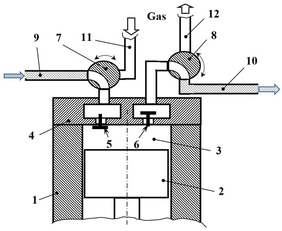
Figure 1.
Schematic diagram of PHPM with regenerative heat exchange (1—cylinder; 2—piston; 3—working chamber; 4—valve head; 5—suction valve; 6—discharge valve; 7, 8—three-way valves; 9—liquid suction line; 10—liquid discharge line; 11—gas suction line; 12—gas discharge line).
During the time interval τ1, the PHC works in the compressor mode. In this case, the walls of the working chamber are heated from the initial temperature to a certain limiting temperature due to the removal of the gas compression heat. Accumulation of the thermal energy in the chamber walls leads to the reduction of the compressor efficiency. When a certain wall temperature is reached after time interval τ1, the PHC switches the operation mode from a compressor to a pump. In the pump mode, the parts of the cylinder–piston group are intensively cooled by the pumping liquid during the time interval τ2. Then, the studied system returns to the compressor mode and the cycle repeats.
Thus, a new technical solution has been implemented to remove the heat of the compressible gas by pumping the coolant through the compressor’s working chamber. As there is no thermal resistance of the working chamber wall, this type of heat exchange (regenerative) is the most efficient. This removal of the compression heat can be used in almost all piston compressors.
A survey of heat transfer in piston compressors shows that little attention has been paid to modelling heat transfer and evaluating its impact. This is partly due to the lack of consensus on its impact and partly due to its complexity [15]. However, many researchers consider the heat exchange inside the cylinder as one of the main factors affecting the efficiency of piston compressors. Piston compressor workflow models benefit from accuracy when heat transfer is taken into account [16,17]. In fact, adiabatic compressors involve a heat flow to and from the walls, which can cause exergy losses, even if the time sum is zero, due to the heating and cooling of the liquid [18,19]. The isothermal compression process in compressors associated with their maximum possible efficiency requires knowledge of the heat transfer phenomena inside the cylinder [20]. Researchers who used heat transfer calculations in their models obtained more accurate results [21,22]. A comparative analysis of heat transfer models for piston compressors showed that the isentropic efficiency of the compressor depends on the type of heat transfer model [23]. They also presented an analysis of heat transfer in a piston compressor cylinder using complex CFD modelling. The results showed a large deviation between the integral correlations and the numerical model for predicting heat transfer [24]. This illustrates the importance and complexity of heat transfer models in piston compressors.
The heat exchange processes in the working chamber and in the cylinder–piston group can be studied theoretically and experimentally. At this stage of the research, a theoretical study is carried out to determine the theoretical limits of the suggested design of PHC. A numerical model of unsteady heat transfer in the compressor working chamber coupled with a thermodynamic cycle is reported in the present paper.
2. Theoretical Models
The low-capacity single-cylinder compressor DECO DKAC09AIR was taken as a basis design in the present study. Figure 2 shows the section of its cylinder–piston group. This compressor is air-cooled and has a cylinder–piston group with a seal and a strainer of O-rings.
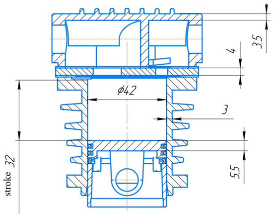
Figure 2.
Section of cylinder–piston group of DKAC09AIR compressor used as basis in the study.
2.1. Assumptions and Governing Equations
An increase in the temperature of the working chamber surfaces deteriorates the compressor’s efficiency [25]. Therefore, the determination of the temporal variation of temperatures requires a consideration of two-way coupled heat exchange in the compressor chamber and corresponding thermodynamic cycle. Due to the extreme complexity of the given processes, several simplifications are required.
Heat transfer from the compressed gas to the inner surface of the compressor chamber is carried out by convection, which dominates over conduction and radiation [26]. The empirical Newton’s law of convection reads:
where dτ is the infinitesimal time interval and dF is the elementary surface area.
The convection coefficient, , depends on the local or mean gas velocity in the vicinity of the heat exchange surface and thus varies with time due to velocity dependence on the instantaneous piston position. Moreover, the piston can be considered to be a source of compression waves. In [27], the shock compression wave was determined from the expression for the piston’s velocity. The instantaneous local gas speed in the cylinder during compression changes at the stroke from the piston speed to zero on the surface of the valve plate.
It is known that gas flow induces vortices in the vicinity of the non-axisymmetric arrangement of the valves. In addition, the turbulence intensity of the flow is higher during the suction compared to the discharge process. This is due to fast gas expansion in the valve’s cross-section. The determination of accurate values of convection coefficient in such a complicated flow requires a numerical solution of the full system of Reynolds-Averaged Navier–Stokes (RANS) equations combined with an appropriate semi-empirical turbulence model [28]. Simulating the gas flow within the RANS model will substantially complicate the considered problem and, on the other hand, will not necessarily lead to improvement in the accuracy of the predicted heat transfer. In the present study, the average values of the convection coefficient, , are determined based on the empirical correlations as discussed in the following.
The unsteady heat transfer in the cylinder–piston group is governed by the heat diffusion equation that should be taken without internal heat sources [29]:
where . The previous theoretical and experimental studies indicate the significant variation in the temperatures over the surface of the working chamber. The greatest temperature non-uniformity is observed on the piston surface, and can rise up to 90 K between the zone of the suction and discharge valves [30]. There is a change in surface temperature both during the cycle time and from cycle to cycle.
Further assumptions were divided into two groups: (1) simplifications in the compressor thermodynamic cycle; (2) simplifications in the heat transfer.
2.1.1. Thermodynamic Cycle Simplifications
The following assumptions were adopted, in accordance with [30]:
- The simulated processes are reversible and at equilibrium;
- The fluid (gas) is considered to be continuous;
- The compressed gas is single-phase;
- The variation in the hydrostatic and dynamic energy of the gas is negligible;
- The properties of the fluid follow the perfect gas state equation;
- The heat exchange between the gas and the walls of the compressor chamber is carried out by convection alone and described by Newton’s law;
- A simplification of the lumped parameters is adopted in the modelling of leakages and of the flow through the valves [30]: the gas flow is one-dimensional, isotropic, and in a quasi-steady-state, and the hydraulic coefficients are taken for the steady-state flow;
- The spatial variation of the convection coefficient across the compressor chamber is neglected, i.e., the spatially averaged convection coefficient is accounted for. The temporal variation of this coefficient is related to the instantaneous velocity of the piston.
2.1.2. Unsteady Heat-Transfer Simplifications
- The complex internal surface of the compressor chamber is split into three simple elements: a cylinder head (valve plate) of constant thickness, a piston of constant thickness, and a cylinder with no fins on its outer surface—see Figure 3;
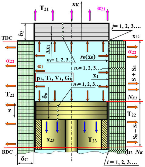 Figure 3. Scheme of unsteady heat-transfer modelling in cylinder-piston group.
 - The piston and the valve plate are considered to be radially unconstrained, i.e., one-dimensional heat transfer is assumed;
- There is no internal heat generation in the elements of the chamber;
- The external heat convection coefficient is approximated based on the experimental studies;
- The thermophysical properties of the materials are independent of temperature and pressure.
The modelling scheme of the cylinder–piston group involving the adopted simplifications is depicted in Figure 3.
2.2. Numerical Methods for Transient Heat-Transfer
The following system of equations is used to simulate the unsteady heat exchange caused by the thermal conductivity in the elements of the chamber:
Equations (3) and (4) are written in the Cartesian coordinate system for the valve plate and the piston head, respectively, and Equation (5) was written in the cylindrical coordinate system for the cylinder walls. Taking into account the simplifications listed in Section 2.1.2, and assuming the problem to be axisymmetric, the system containing (3)–(5) is reduced to:
The given system of equations is expected to be coupled with the compressor thermodynamic cycle by appropriate boundary conditions as discussed below. This significantly restricts analytical approaches, making them practically inapplicable. On the contrary, the given problem can be solved numerically with one of the following methods: finite difference (FDM) [31,32], finite volume (FVM) [33,34], finite element (FEM) [35,36], meshless methods [37,38], boundary element (BEM) [39,40], or some other techniques [41,42,43].
One of the most effective numerical approaches is the so-called implicit tridiagonal matrix algorithm [44], which is used in the present study. In this method, the coefficients are determined in the “forward sweep”, while the temperature values are determined in the “back substitution” using the obtained coefficients. In the following, we discuss the implementation of the algorithm in Cartesian and cylindrical coordinates, respectively.
2.2.1. Cartesian Coordinates: Cylinder Head and Piston
In the first time loop, the coefficients are found as follows:
and for the subsequent loops, they are found by:
The integration coordinate is determined as , and the current integration time is determined as . To determine the temperature values in the “back substitution” step, the following recursive formula is used:
The boundary conditions of the third kind are used to determine the surface temperatures and (see Figure 3):
2.2.2. Cylindrical Coordinates: Cylinder Walls
In this case, integration is performed along two spatial coordinates. When integrating the temperature field along the radial axis, r, Equation (8) is reduced to:
The coefficients in the forward sweep are as follows:
where . The temperature values in the back substitution are:
When integrating the temperature field along the longitudinal axis, z, Equation (8) is converged to:
The form of this equation is similar to that of the Cartesian coordinates, i.e., (6) and (7). In this case, the coefficients in the forward sweep are:
In the back substitution, the temperature values are:
It is required to distinguish three zones along the cylinder wall in order to impose the boundary conditions (see Figure 4): (I) internal surface of the cylinder between its head and the upper surface of the piston; (II) contact region between the cylinder and the piston; (III) the cylinder surface below the piston.
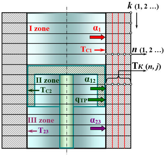
Figure 4.
Three zones along cylinder with appropriate boundary conditions.
The total number of nodes, K, along, z, the axis is:
The distribution of the nodes between the defined zones is as follows:
In zone I, the convection coefficient α1 and the surface temperature, Tc1, are defined by the compressor thermodynamic cycle. The distribution of temperature in the radial direction is:
In zone II, the friction between the piston’s O-rings and the cylinder leads to the generation of contact heat, which adds to the convective heat transfer. The temperature of the cylinder surface in this case is:
Temperature, , is defuned by Formula (28).
In zone III, the value of is defined as:
The outer wall temperature in zone III is also determined by Formula (28).
Both the first-kind and third-kind boundary conditions can be set in the longitudinal direction, z. For the first-kind boundary conditions, the temperature will read:
The third-kind boundary conditions will define the temperatures on the top and the bottom surfaces of the cylinder as follows:
2.3. Thermodynamics of Compressor Cycle
There are three degrees of mathematical simplification: mathematical models with distributed parameters, those with lumped parameters, and those based on polytropic approximation. As discussed above, the application of distributed parameters models, such as RANS, is substantially restricted due to the extreme requirements for temporal and spatial resolutions to be resolved combined with the large time scales of the heat transfer processes. The complexity is further enhanced by the temporal variability of the domain’s geometry caused by the motion of the piston. On the other hand, the polytropic approximation of gas compression is oversimplified, leading to the low accuracy of the results, as well as the inability to account for the impact of the chamber surface temperature on the thermodynamic process.
In this study, we use the lumped approximation to model the thermodynamic cycle of the compressor. The introduced assumptions are listed in Section 2.1.1. The principle scheme used to derive the thermodynamic model is depicted in Figure 5.
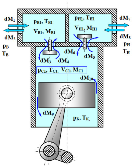
Figure 5.
Principal scheme of PHC used in derivation of thermodynamic lumped model.
The governing equations of the lumped thermodynamic model incorporate the energy conservation equation (the first law of thermodynamics) for the gas, which has a variable volume and mass; the mass conservation equation; the equation of chamber volume variation due to piston motion; the equation for the dynamics of self-acting valves; the equation for a perfect gas state. This system of equations is written for three control volumes (see Figure 5)—that of the intake chamber, compression chamber, and discharge chamber:
There are two approaches in the determination of the heat transfer, , between the compressed gas and the chamber walls. The first one is based on the area-averaged temperature of the compression chamber surface:
The heat exchange surface, , can be defined as:
and the area average temperature of the cylinder surface can be defined as:
where . In this this approach, the heat flow to or from the compressed gas reads:
Alternatively, the value of can be sought as a sum of the heat flows to or from different elements of the compression chamber:
The individual terms in this expression are as follows:
The convection coefficient in the compression chamber is parametrized with empirical correlations. It is known that the mean Nusselt number in the compressor chambers is predominantly dependent on the mean Reynolds number, varying in time together with the piston velocity. In this study, we use the Prilutsky–Fotin empirical correlation:
A, B, and x are known constants.
The mass flow rates are calculated based on the Saint-Venant–Wanzel formula, taking into account the assumptions made in Section 2.1.1. The lumped mass formulation is implemented to take into account the dynamics of the intake and discharge valves, while the forces acting on the valves are determined in accordance with [30].
2.4. Implementation of the Numerical Model
The integration time step, ∆τ, is a crucial parameter impacting the accuracy and stability of computations. Since we consider two closely coupled models, two integration steps need to be selected: ∆τ1 will be used to solve the unsteady heat diffusion equations, and ∆τ2 will be used to resolve the thermodynamic model (33)–(47). In general, their values do not coincide. To keep the computation efficient, the values of both ∆τ1 and ∆τ2 need to be as high as possible. On the other hand, an excessive increase in the time step will lead to the instability of numerical methods and, consequently, to computational inaccuracies. Thus, particular attention should be paid to selection of those values.
2.5. Selection of the Diffusion Equation Integration Step ∆τ1
It is shown in [44] that the tridiagonal matrix algorithm is stable when . The approximation error is of . To study the lower limit of ∆τ1, the accuracy of the tridiagonal matrix algorithm will be compared with that of the finite element software ANSYS, allowing the automatic selection and adjustment of the integration step. To this end, several simulations with different parameters S and ∆τ1 are to be executed.
A simplified problem focused specifically on the unsteady heat transfer is considered in this section, namely an infinite plate of thickness, . The following third-kind boundary conditions are imposed on the plate: α1 = 400 W/m2K, T1 = 400 K; α2 = 10 W/m2K and T2 = 293 K. The number of nodes in the tridiagonal matrix algorithm was selected as i = 20, and the spatial resolution was ∆x = 0.00025 m.
Figure 6 shows the temperature of the inner surface, , as a function of time obtained by selecting different values for S and ∆τ1. It is seen that selection S = 224 shows an initial growth in the surface temperature to 332 K followed by the subsequent maintenance of this value. This trend is drastically different from the results of the ANSYS computation, which is probably due to the insufficient numerical accuracy of the tridiagonal matrix algorithm. A reduction in S leads to a convergence between the tridiagonal matrix algorithm and the finite element solution. The divergence between the results remains in the interval 4 to 5 K.
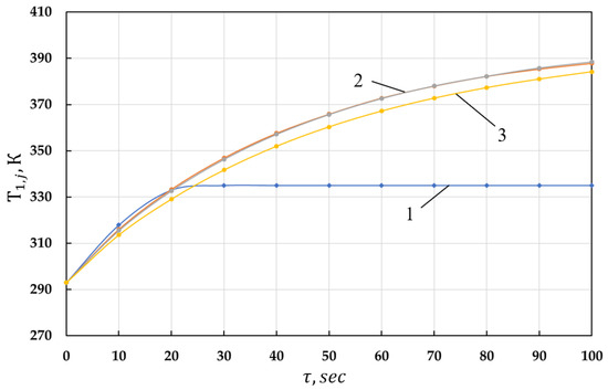
Figure 6.
Comparative analysis of the tridiagonal matrix lgorithm with different values for S parameter against ANSYS finite element software(1: S = 224; 2: S = 11.21 and S = 22.42; 3: ANSYS).
The dependence of the temperature divergence, ∆T, between the tridiagonal matrix and finite element methods on the parameter S was studied is shown in Figure 7. It is seen that the optimal value of S should be in the range between 40 and 60 W/s∙K. Smaller values of S lead to faster but less accurate computation.
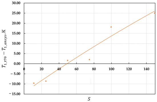
Figure 7.
Dependence of temperature divergence between tridiagonal matrix and finite element methods on parameter S. Duration of the simulations was 70 s.
Figure 8 shows the variation in time of the temperature difference between the inner and outer surfaces of the plate obtained by the use of different values of S. It is seen that the maximum difference between the tridiagonal matrix and finite element methods is reached at τ = 40 s and equal to 0.154 K. Moreover, the temperature divergence tends to reduce with a longer time.
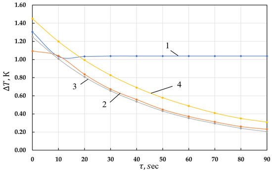
Figure 8.
Dependence of temperature difference between inner and outer surfaces of the plate on time (1: S = 224; 2: S = 22.42; 3: S = 11.21; 4: ANSYS).
Since a significant portion of the heat flow transfers through the cylindrical wall of the compression chamber, we consider the unsteady heating of the geometrically simplified cylinder as a second test case. Several boundary conditions, including those of the first and third kind, will be examined.
Figure 9 shows the computational domain corresponding to the cylinder with the third-kind boundary conditions imposed on its inner and outer surfaces, and the first-kind boundary conditions imposed on its upper and lower boundaries (i.e., T = 300 K). The full piston stroke here is 0.032 m, which is discretized by 85 grid nodes (K1 = 85). The length of the piston contact region is 0.004 m, split into K2 =15 grid nodes. The temperature on the inner surface of the cylinder in the contact area is set to 310 K.
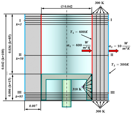
Figure 9.
Calculation scheme of a cylinder with boundary conditions applied to it.
The tridiagonal matrix algorithm was applied to solve the problem, and the simulation results are summarized in Table 1 for two physical times: τ1 = 33.35 s and τ2 = 66.576 s. The results are presented for three cross-sections of the cylinder: those corresponding to node numbers K = 3, K = 50, and K = 95, respectively. The presented results demonstrate the propagation of thermal energy in both transversal and longitudinal directions. The tridiagonal matrix algorithm was found to demonstrate reasonable accuracy.

Table 1.
Simulation results of heat transfer in cylindrical coordinates obtained by the tridiagonal matrix method.
2.6. Selection of the Time Step ∆τ2 in the Thermodynamic Model
Two main approaches can be recognized in modelling the compressor thermodynamic cycle. According to the first one, the temperature and pressure variation in time, τ, or in the crank angle, φ, is governed by a set of ordinary differential equations in the following form:
These equations are usually solved numerically by the 4th or higher order Runge–Kutta method allowing fixed or adjusted integration step ∆τ2 or ∆φ.
Another approach [45] is based on the conservation of the total internal energy in the control volume. This approach was found to be significantly more stable and robust due to intrinsic properties, thus allowing the application of both Runge–Kutta or the simpler Euler method. However, it was quite sensitive to the size of the control volume, which required a significant reduction in the integration step when dealing with relatively small volumes, such as that of the compression chamber.
The stability analysis demonstrated the time-step-independent solution of Equations (33)–(47) when the crank angle step was set to , which corresponds to and the angular velocity of the compressor shaft, which corresponds to . As one can see, the ratio between ∆τ1 and ∆τ2 can be in the range of 200 to 1000.
3. Results and Discussion
The unsteady heat transfer in the compressor mode of the PHC was studied— see Figure 1. The following geometrical and physical parameters were selected— see Table 2. For details, refer to Figure 10.

Table 2.
Main parameters of the PHPM.
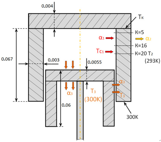
Figure 10.
Main geometric and physical parameters assumed in numerical analysis.
The spatial resolution of the computation grid was as follows: 20 nodes were used to discretize the piston and cylinder head plates; the full length of the cylinder was divided into 100 nodes, while in the radial direction, it was split between 20 nodes. The following designations were adopted in the analysis: the surface temperature of the valve plate, ; the upper surface temperature of the piston, the inner surface temperature of the cylinder, (50); the area-averaged temperature of the compression chamber surface, (48).
Figure 11 depicts the variation in time of the designated temperatures obtained for the different values of the shaft revolution speed. Parabolic fitting was used to interpolate the discrete temperature values predicted in the simulation. It was seen that the interpolation curves asymptotically approached the thermodynamic equilibrium temperature. The valve plate was found to be the hottest part of the domain followed by the piston, while the mean temperature of the cylinder seemed to be the smallest one. The average temperature of the entire surface of the compression chamber exceeded the cylinder surface temperature by 10–15 K.
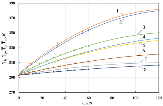
Figure 11.
Temperature variation in time for different parts of the cylinder–piston group: 1— for discharge pressure p = 0.5 MPa and shaft revolution speed nrev = 2000 rpm; 2— for p = 0.5 MPa and nrev = 2000 rpm; 3— for p = 0.5 MPa and nrev = 1000 rpm; 4— for p = 0.5 MPa and nrev = 1000 rpm; 5— for p = 0.5 MPa and nrev = 2000 rpm; 6— for p = 0.5 MPa and nrev = 1000 rpm; 7— for p = 0.5 MPa and nrev = 2000 rpm; 8— for p = 0.5 MPa and nrev = 1000 rpm.
Additionally, an increase in the shaft revolution speed from 1000 rpm to 2000 rpm resulted in significant growth (up to 15 K) in the temperatures of the piston and the valve plate, which was related to the growth in the compressor discharge temperature of the gas. The most notable growth in temperature while increasing the shaft revolution speed was observed on the surface of the cylinder, which added up to around 20 K.
The impact of the discharge pressure value on temperatures was studied and is shown in Figure 12. Increases in the pressure led to the growth in the gas temperature in the thermodynamic cycle and in the corresponding intensification of the heat transfer. The most significant temperature growth was observed on the surfaces of the valve plate and piston, tending to be 8–10 K after 120 s of the physical time. On the other hand, the variation in the mean temperature on the cylinder surface was negligible and was less than 1 K.
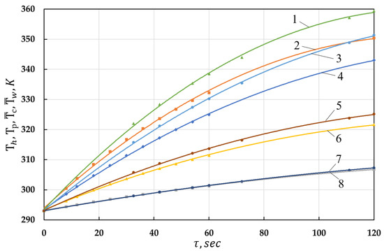
Figure 12.
Same as Figure 11 for various discharge pressure: 1— for p = 0.6 MPa and nrev = 1000 rpm; 2— for p = 0.5 MPa and nrev = 1000 rpm; 3— for p = 0.6 MPa and nrev = 1000 rpm; 4— for p = 0.5 MPa and nrev = 1000 rpm; 5— for p = 0.6 MPa and nrev = 1000 rpm; 6— for p = 0.5 MPa and nrev = 1000 rpm; 7— for p = 0.6 MPa nrev = 1000 rpm; 8— for p = 0.5 MPa and nrev = 1000 rpm.
Figure 13 demonstrates the reduction in the heat flow through the compression chamber walls with time. Moreover, a similar trend was observed for the total heat flow per thermodynamic cycle, , as well as for the heat flow during the gas compression alone, . Since the heat flow as directed from the compressed gas toward the solid walls, its value was negative. The performed simulations suggest that the overall heat flow from the compressed gas to the environment consisted of the mean- and time-fluctuating components, which is fully in line with the widely accepted theory.
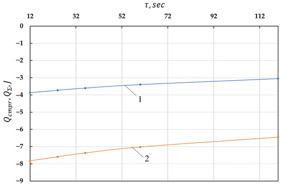
Figure 13.
Time variation in overall heat flow per single thermodynamic cycle, (curve 1), and that for the compression process only, (curve 2).
It is seen that both and depended almost linearly on time, while ws nearly twice higher than due to the impact of the gas expansion process. The reduction of impacted directly the polytropic index of the process, thermodynamic efficiency, and volumetric efficiency, as demonstrated in Figure 14. The variation in the polytropic index in time was close to parabolic, while the other indicators were almost linear in time. One can see that after 120 s the isothermal, adiabatic, and volumetric efficiencies decreased by 3%, 3.5%, and 2.5%, respectively, which is quite significant.
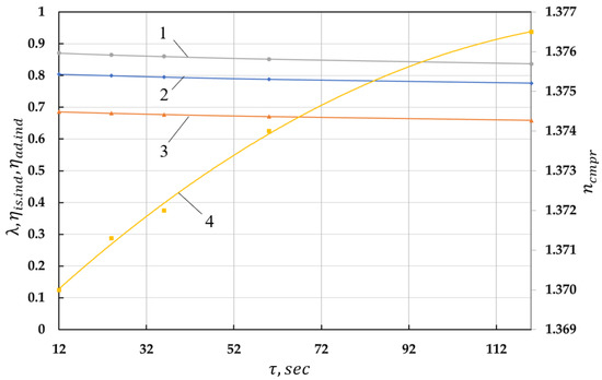
Figure 14.
Time variation of isothermal ( ) and adiabatic () efficiency, volumetric efficiency (), and polytropic index (): 1—; 2—; 3—; 4—. Here, the volumetric efficiency is the ratio of the actual mass flow rate produced by the compressor to the ideal value.
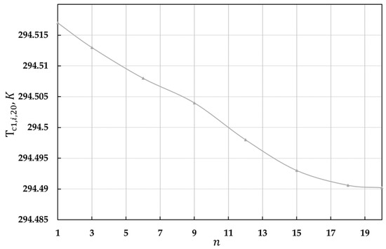
Figure 15 demonstrates the temperature distribution in the body of the piston and the cylinder head at the physical time during the gas compression process when the shaft angle was φ = π. The maximum temperature value was seen at node number three, with the coordinate xi = 0.006 m. The temperature difference between the opposite sides of the plates was negligible and equal to 0.16 K, which is related to the low value of the convection coefficient at the outer sides of the plates. Note that the cylinder head surface temperature exceeded that of the piston surface by 5.4 K. A monotonic temperature drop of 0.33 K was observed in the piston body.
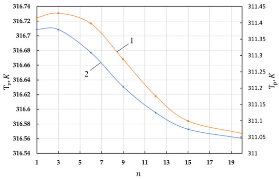
Figure 15.
Temperature distribution in the body of the valve plate (curve 1) and piston (curve 2). Here, n is the number of the grid nodes.
The temperature distributions in three cross-sections corresponding to the number of grid nodes K = 5, 16, and 20 are depicted in Figure 16, Figure 17 and Figure 18. The initial increase in temperature followed by its subsequent reduction was found in section K = 5. Two temperature maxima were observed in section K = 16, while section K = 20 demonstrated a monotonous decline in temperature.
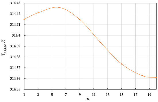
Figure 16.
Temperature distribution across the cylinder wall in the cross-section K = 5. Here, n is the number of grid nodes.
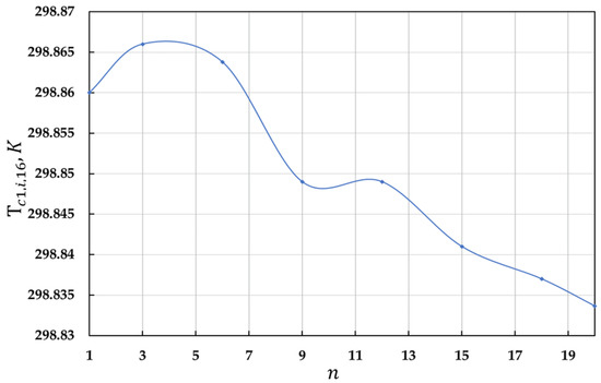
Figure 17.
Same as Figure 16 for the cross-section K = 16.
The surface temperature of the cylinder decreased in the longitudinal direction from the cylinder head temperature to 300 K, which was imposed on its bottom edge. However, the temperature dropped below 300 K in the cross-section K = 20 because of the wall cooling during the gas expansion process. Intensifying the external heat transfer by increasing the convection coefficient α2 and by the additional reduction of the environmental temperature was expected to diminish the temperature of the cylinder–piston group components.
4. Conclusions
- Starting from the system of assumptions, the thermodynamic model was coupled with the unsteady heat transfer model to study the novel piston hybrid compressor (PHC) with regenerative heat exchange.
- The implicit tridiagonal matrix algorithm was implemented to solve the unsteady thermal diffusion equation subject to boundary conditions of the first and third kinds. The properties of the numerical method were discussed.
- Numerical stability analysis was performed to determine the ratio between the spatial and temporal resolutions adopted in the tridiagonal matrix algorithm, which ensure the minimization of the computational time while maintaining sufficient accuracy. The finite element solution obtained in the ANSYS software was used as a reference for the comparison of the computation results.
- The integration time step was determined for the thermodynamic model, which was strongly coupled with the heat transfer processes. It was found to be substantially smaller compared to the heat transfer temporal resolution, which is attributed to the relatively small size of the compressor chamber.
- Several numerical experiments were executed using the strongly coupled thermodynamic and heat transfer models which were developed. The following conclusions can be made:
- The developed numerical model allowed the retrieval of the time variation of the temperatures in the components of the piston hybrid compressor;
- The dynamics of the heat flows, as well as the integral energetic characteristics of the compressor were studied with consideration of the isothermal, adiabatic, and volumetric efficiencies. A reduction in all efficiencies of around 3% was reported for the studied time interval of 120 s.
- The heat flow through the compressor chamber walls was divided into the mean and the oscillating parts. The existence of the non-zero mean heat flow contribution was demonstrated and was in agreement with the existing theories. Moreover, the temperature variation at the compressor chamber surfaces was found to be less than 1 K, which is also supported by the available literature.
Author Contributions
Conceptualization, V.S.; methodology, V.S.; software, A.K.; validation, E.P.; formal analysis, E.P.; investigation, A.K.; resources, A.K. and E.P.; data curation, A.K.; writing—original draft preparation, E.N.; writing—review and editing, E.P.; visualization, A.K.; project administration, V.S. All authors have read and agreed to the published version of the manuscript.
Funding
The study was supported by the Russian Science Foundation, grant no. 22–29-00399, https://rscf.ru/project/22–29-00399/ (13 January 2023).
Data Availability Statement
Data sharing not applicable. No new data were created or analyzed in this study. Data sharing is not applicable to this article.
Conflicts of Interest
The authors declare no conflict of interest.
Nomenclature
The nomenclature of the paper is shown below:
| A | the experimentally determined constants in the correlation for the Nusselt number (A = 0.2 ÷ 0.235); |
| the thermal diffusivity of the cylinder, m2/s; | |
| the thermal diffusivity of the piston material, m2/s; | |
| the thermal diffusivity of the cylinder head, m2/s; | |
| B | the experimentally determined constants in the correlation for the Nusselt number (B = 500 ÷ 800); |
| the elementary masses of the gas passing during time interval through various cross-sections, kg; | |
| the isobaric specific heat capacy, J/(kg·K); | |
| the isochoric specific heat capacity, J/(kg·K); | |
| the specific heat capacity of the materials of the cylinder head, J/(kg·K); | |
| the specific heat capacity of the piston, J/(kg·K); | |
| the specific heat capacity of the cylinder, J/(kg·K); | |
| the heat exchange surfaceof the piston, m2; | |
| the heat exchange surface of the cylinder head, m2; | |
| the heat exchange surface of the cylinder, m2; | |
| h | the stroke of the valves, m; |
| i | the specific enthalpy of the gas, J; |
| the adiabatic index of the gas (indices “sc”, “sc1”, “cmprs1”, “d1”, and “d” refer to the suction gas, the suction cavity, the compression chamber, the discharge cavity, and the discharge gas, respectively); | |
| the piston length, m; | |
| the length of the cylinder, m; | |
| the mass of the gas, kg; | |
| the reduced mass of the valves, kg; | |
| nrev | the number of revolutions per minute of the compressor shaft, rpm; |
| the area-averaged Nusselt number; | |
| the pressure of the gas, Pa; | |
| the gas discharge pressure, Pa; | |
| the heat flux density vector, W/m2; | |
| the internal heat generation, W/m3; | |
| the specific heat flux caused by friction forces, W/m2; | |
| r | the radial coordinate, m; |
| the gas constant (indices “sc”, “sc1”, “cmprs1”, “d1”, and “d” refer to the suction gas, the suction cavity, the compression chamber, the discharge cavity, and the discharge gas, respectively), J/(mol·K); | |
| ) | the Reynolds number as a function of the angular shaft coordinate; |
| the current stroke of the piston, m; | |
| S | the convergence parameter of the difference scheme; |
| Sd | the size of the dead volume, m; |
| the stroke of the piston, m; | |
| the temperature of gas, K; | |
| the suction temperature, K; | |
| the temperature of the piston, K; | |
| the temperature of the cylinder head, K; | |
| the temperature of the cylinder, K; | |
| the gas temperature gas in the compressor chamber, K; | |
| the environmental air temperature, K; | |
| the cylinder head temperature at the contact with the cylinder itself, K; | |
| the crankcase temperature at the point of contact with the lower cylinder surface, K; | |
| the temperature of the gas at the time , K; | |
| the temperature of the wall surface with , K; | |
| the total gas internal energy, J; | |
| the volume of the gas, m3; | |
| the dead volume of the compressor chamber, m3; | |
| the total volume of the compressor chamber, m3; | |
| the instantaneous velocity of the piston, m/s; | |
| x | the experimentally determined constants in the correlation for the Nusselt number (x = 0.8 ÷ 0.86); |
| the convection heat transfer coefficient in the compressor chamber, W/(m2·K); | |
| the convection heat transfer coefficient, W/(m2·K); | |
| the convection heat transfer coefficient between the gas located near at the time , W/(m2·K); | |
| the area-averaged convection heat transfer coefficient, which is a function of the angular shaft coordinate, W/(m2·K); | |
| ∆x | the spatial integration step; |
| the temporal integration step; | |
| the thermal conductivity of the piston, W/(m·K); | |
| the thermal conductivity of the cylinder head, W/(m·K); | |
| the ratio of the piston stroke to the doubled length of the rod; | |
| the thermal conductivity of the gas, W/(m·K); | |
| the dynamic viscosity of the gas, Pa·s; | |
| the density of the gas, kg/m3; | |
| the density of materials of the cylinder head, kg/m3; | |
| the density of materials of the piston, kg/m3; | |
| the density of materials of the cylinder, kg/m3; | |
| the sum of forces acting on the valves, N; | |
| τ | the current physical time, s; |
| the angular coordinate of the compressor shaft, grad; | |
| the angular velocity of the shaft, rad/s. |
References
- Radgen, P. Efficiency through Compressed Air Energy Audits. In Proceedings of the Energy Audit Conference, Lahti, Finland, 11–13 September 2006. [Google Scholar]
- Xiaolin, T. Energy Consumption and Energy Saving Research Status of Air Compressor System. In Applied Mechanics & Materials; Xiaolin, T., Shougen, H., Hongbo, Q., Eds.; Trans Tech Publications Ltd.: Zürich, Switzerland, 2014; Volume 628, pp. 225–228. [Google Scholar]
- Sychkov, A.E. The role of efficient cooling systems in modern compressor installations. Megapascal 2009, 4, 36–40. [Google Scholar]
- Mousavi, S. Energy efficiency of compressed air systems. Procedia CIRP 2014, 15, 313–318. [Google Scholar] [CrossRef]
- Tuhovcak, J.; Hejcik, J.; Jicha, M. Comparison of heat transfer models for reciprocating compressor. Appl. Therm. Eng. 2016, 103, 607–615. [Google Scholar] [CrossRef]
- Patil, V.C.; Acharya, P.; Ro, P.I. Experimental investigation of heat transfer in liquid piston compressor. Appl. Therm. Eng. 2019, 146, 169–179. [Google Scholar] [CrossRef]
- Shcherba, V.E.; Aver’yanov, G.S.; Kalekin, V.S.; Korneev, S.V.; Tegzhanov, A.S. Calculation of Rational Values of Discharge Pressures in the Compressor and Pump Sections of a Crossheadless Reciprocating Hybrid Power Machine. Chem. Pet. Eng. 2018, 54, 418–424. [Google Scholar] [CrossRef]
- Shcherba, V.E.; Shalai, V.V.; Nosov, E.Y.; Kondyurin, A.Y.; Nesterenko, G.A.; Tegzhanov, A.S.; Bazhenov, A.M. Comparative Analysis of Results of Experimental Studies of Piston Hybrid Energy-Generating Machine with Smooth and Stepped Slot Seals. Chem. Pet. Eng. 2018, 54, 499–506. [Google Scholar] [CrossRef]
- Shcherba, V.E.; Shalai, V.V.; Grigor’ev, A.V.; Kondyurin, A.Y.; Lysenko, E.A.; Bazhenov, A.M.; Tegzhanov, A.S. Analysis of results of theoretical and experimental studies of the influence of radial gaps in stepped slot seal of piston hybrid energy-generating machine. Chem. Pet. Eng. 2018, 54, 666–672. [Google Scholar] [CrossRef]
- Shcherba, V.E.; Shalai, V.V.; Kondyurin, A.Y.; Ovsyannikov, A.Y.; Dorofeev, E.A.; Kryukov, K.S. Influence of Deformation, Mass Transfer, and Heating on Pump Compression. Russ. Eng. Res. 2019, 39, 1–5. [Google Scholar] [CrossRef]
- Shcherba, V.E.; Shalai, V.V.; Kuzhbanov, A.K.; Zaloznov, I.P.; Kryukov, K.S.; Tegzhanov, A.S. Utilization of Compressed Gas Heat for Fluid Compression and Movement in a Displacement Pump. Chem. Pet. Eng. 2019, 55, 216–222. [Google Scholar] [CrossRef]
- Pat. for the invention 2686536 Russian Federation, IPC F 04 B 19/06. Hybrid volumetric machine with a tron piston. In Applicant and Patent Holder; Shcherba, V.E., Tegzhanov, A.S., Bolshtyansky, A.P., Nosov, E.Y., Eds.; Omsk State Techn. University: Omsk, Russia, 2018. [Google Scholar]
- Development of a Prototype of Crosshead-Free Piston Hybrid Power Machine; Shcherba, V.E., Tegzhanov, A.S., Nosov, E.Y., Eds.; Bulletin of Irkutsk State Technical University: Irkutsk, Russia, 2018; Volume 22. [Google Scholar]
- Russian Federation. Method of Operation of the Liquid Cooling System of a Volumetric Machine and Device for Its Implementation. Patent 2763099, 27 December 2021.
- Prasad, B.G.S. Heat Transfer in Reciprocating Compressors—A Review. In Proceedings of the ASME 1998 International Mechanical Engineering Congress and Exposition, Anaheim, CA, USA, 15–20 November 1998; Paper 1349. Available online: https://docs.lib.purdue.edu/icec/1349 (accessed on 4 January 2023).
- Adair, R.P.; Qvale, E.B. Pearson Instantaneous Heat Transfer to the Cylinder Wall in Reciprocating Compressors. Proc. Purdue Compress. Conf. 1972, 521–526. [Google Scholar]
- Liu, Z.; Yang, X.; Yang, X.; Zhai, H.; Duan, Z. Performance Evaluation on the In-Cylinder Heat Transfer of a Reciprocating Compressor using CO2 as a Working Fluid. J. Therm. Sci. 2022, 31, 1518–1530. [Google Scholar] [CrossRef]
- Ocheduszko, S. Teoria Maszyn Cieplnych, ume 3; Państwowe Wydawnictwo Naukowe: Warszawa, Poland, 1953. [Google Scholar]
- Szargut, J. Exergy Method: Technical and Ecological Applications; WIT Press: Cambridge, MA, USA, 2005; Volume 18. [Google Scholar]
- Mahbod, H.; Mehdi, M.; Alfred, R. Design, modeling and experimental validation of a novel finned reciprocating compressor for isothermal compressed air energy storage applications. Energy 2017, 140, 1252–1266. [Google Scholar]
- Maria, A.C.; Michael, S.; Sapin, P.; Christos, N. Markides Off-design optimisation of organic rankine cycle (orc) engines with piston expanders for medium-scale combined heat and power applications. Appl. Energy 2019, 238, 1211–1236. [Google Scholar]
- Richard, M.; Christos, N.M.; Alexander, J. White A framework for the analysis of thermal losses in reciprocating compressors and expanders. Heat Tran. Eng. 2014, 35, 1435–1449. [Google Scholar]
- Recktenwald, G.W.; Ramsey, J.W.; Patankar, S.V. Predictions of Heat Transfer in Compressor Cylinders. In Proceedings of the International Compressor Engineering Conference, West Lafayette, IN, USA, 4–7 August 1986; Paper 523. Available online: http://docs.lib.purdue.edu/icec/523 (accessed on 4 January 2023).
- Tuhovcak, J.; Jicha, M. Heat Transfer Analysis in the Cylinder of Reciprocating Compressor; Purdue University: West Lafayette, IN, USA, 2016. [Google Scholar]
- Shcherba, V.E. Method for estimating the operating time in the compressor mode of a volumetric piston hybrid power machine with regenerative heat exchange. News of higher educational institutions. Engineering 2022, 751, 96–102. [Google Scholar]
- Plastinin, P.I. Reciprocating Compressors; Kolos: Moscow, Russia, 2006; p. 456. [Google Scholar]
- Landau, L.; Lifshitz, E. Continuum Mechanics. In Hydrodynamics and the Theory of Elasticity; State Publishing House of Technical and Theoretical Literature: Leningrad, Russia, 1944; Volume 3, 624p. [Google Scholar]
- Emtsev, B.T. Technical Hydromechanics; Mashinostroenie: Moscow, Russia, 1987; 440p. [Google Scholar]
- Isachenko, V.P.; Osipova, V.A.; Sukomel, A.S. Heat Transfer/Textbook for Universities, 3rd ed.; Mir Publishers: Moscow, Russia, 1975; 488p. [Google Scholar]
- Cui, M.; Peng, H.F.; Xu, B.B. A new radial integration polygonal boundary element method for solving heat conduction problems. Int. J. Heat Mass Transf. 2018, 123, 252–260. [Google Scholar] [CrossRef]
- Annafi, T.A.; Gyeabour, A.A.; Akaho, E.H.K. Finite difference analysis of the transient temperature profile within GHARR-1 fuel element. Ann. Nucl. Energy 2014, 68, 204–208. [Google Scholar] [CrossRef]
- Cui, M.; Zhao, Y.; Xu, B.B. Inverse analysis for simultaneously estimating multi-parameters of temperature-dependent thermal conductivities of an Inconel in a reusable metallic thermal protection system. Appl. Therm. Eng. 2017, 125, 480–488. [Google Scholar] [CrossRef]
- Li, W.; Yu, B.; Wang, X.R. A finite volume method for cylindrical heat conduction problems based on local analytical solution. Int. J. Heat Mass Transf. 2012, 55, 5570–5582. [Google Scholar] [CrossRef]
- Han, S. Finite volume solution of two-step hyperbolic conduction in casting sand. Int. J. Heat Mass Transf. 2016, 93, 1116–1123. [Google Scholar] [CrossRef]
- Clarac, F.; Goussard, F.; Teresi, L. Do the ornamented osteoderms influence the heat conduction through the skin? A finite element analysis in Crocody lomorpha. J. Therm. Biol. 2017, 69, 39–53. [Google Scholar] [CrossRef]
- Cebula, A. Heat flux and temperature determination in a cylindrical element with the use of Finite Volume Finite Element. Int. J. Therm. Sci. 2018, 127, 142–157. [Google Scholar] [CrossRef]
- Sladek, J.; Sladek, V.; Zhang, C. Transient heat conduction analysis in functionally graded materials by the meshless local boundary integral equation method. Comput. Mater. Sci. 2003, 28, 494–504. [Google Scholar] [CrossRef]
- Joldes, G.R.; Chowdhury, H.; Wittek, A.; Miller, K. A new method for essential boundary conditions imposition in explicit meshless methods. Eng. Anal. Bound. Elem. 2017, 80, 94–104. [Google Scholar] [CrossRef]
- Wrobel, L.C. Boundary Element Methods in Heat Transfer; Wrobel, L.C., Brebbia, C.A., Eds.; Southampton: Boston, MA, USA, 1992; 294p. [Google Scholar]
- Yu, B.; Xu, C.; Yao, W.A.; Meng, Z. Estimation of boundary condition on the furnace inner wall based on precise integration BEM without iteration. Int. J. Heat Mass Transf. 2018, 122, 823–845. [Google Scholar] [CrossRef]
- Ling, J.; Yang, D.S.; Zhai, B.W. Solving the single-domain transient heat conduction with heat source problem by virtual boundary meshfree Galerkin method. Int. J. Heat Mass Transf. 2017, 115, 361–367. [Google Scholar] [CrossRef]
- Hua, T.; Zhao, Y.C.; Guo, Z.Y. Optimization of the one-dimensional transient heat conduction problems using extended entransy analyzes. Int. J. Heat Mass Transf. 2018, 116, 166–172. [Google Scholar] [CrossRef]
- Choi, W.; Ooka, R.; Shukuya, M. Exergy analysis for unsteady-state heat conduction. Int. J. Heat Mass Transf. 2018, 116, 1124–1142. [Google Scholar] [CrossRef]
- Demidovich, B.P.; Maron, I.A.; Shuvalova, E.Z. Numerical methods of analysis. In Approximation of Functions, Differential and Integral Equations, 3rd ed.; Nauka: Moscow, Russia, 1967; 368p. [Google Scholar]
- Fotin, B.S.; Pirumov, I.B.; Prilutsky, I.K.; Plastinin, P.I. Piston compressors. In Proc. Allowance for University Students, Under the Total; Engineering Leningrad Department: Leningrad, Russia, 1987; 372p. [Google Scholar]
Disclaimer/Publisher’s Note: The statements, opinions and data contained in all publications are solely those of the individual author(s) and contributor(s) and not of MDPI and/or the editor(s). MDPI and/or the editor(s) disclaim responsibility for any injury to people or property resulting from any ideas, methods, instructions or products referred to in the content. |
© 2023 by the authors. Licensee MDPI, Basel, Switzerland. This article is an open access article distributed under the terms and conditions of the Creative Commons Attribution (CC BY) license (https://creativecommons.org/licenses/by/4.0/).
