Article

Tactile Force Sensing for Admittance Control on a Quadruped Robot

by
Thijs Van Hauwermeiren
1,2,*,
Annelies Coene
1,2 and
Guillaume Crevecoeur
1,2
1
Department of Electromechanical, Systems and Metal Engineering, Ghent University, 9000 Gent, Belgium
2
Flanders Make Core Lab MIRO, 9000 Gent, Belgium
*
Author to whom correspondence should be addressed.
Machines 2025, 13(5), 426; https://doi.org/10.3390/machines13050426
Submission received: 11 April 2025 / Revised: 9 May 2025 / Accepted: 16 May 2025 / Published: 19 May 2025
(This article belongs to the Section Robotics, Mechatronics and Intelligent Machines)

Abstract

:
Ground reaction forces (GRFs) are the primary interaction forces that enable a legged robot to maintain balance and perform locomotion. Most quadruped robot controllers estimate GRFs indirectly using joint torques and a kinematic model, which depend on assumptions and are highly sensitive to modeling errors. In contrast, direct sensing of contact forces at the feet provides more accurate and immediate feedback. Beyond force magnitude, tactile sensing also enables richer contact interpretation, such as detecting force direction and surface properties. In this work, we show how tactile sensor information can be used inside the feedback of the control loop to achieve compliance of legged robots during ground contact. The three main contributions are (i) a fast and computationally efficient 3D force reconstruction method tailored for spherical tactile sensors, (ii) a tactile admittance controller that adjusts leg motions to achieve the desired GRFs and compliance, and (iii) experimental validation on a quadruped robot, demonstrating enhanced load distribution and balance during external perturbations and locomotion. The results show that the peak ground reaction forces were reduced by 55% while balancing on a beam. During a locomotion scenario involving sudden touchdown after a fall, the tactile admittance controller reduced oscillations and regained stability compared to proportional–derivative (PD) control.

1. Introduction

Legged quadrupedal robots have seen a rapid increase in deployment and capabilities [1,2,3]. By design, quadruped robots have an excellent trade-off between maneuverability, stability, and payload capacity [4]. These robots carry considerable potential for automation in tasks such as inspection [5,6], regular maintenance [7], and exploration of rugged terrains [8]. Recently, a number of methods for controlling legged robots have been developed, either employing a model predictive control paradigm [9,10] or through the use of reinforcement learning [11,12]. However, in most prior works, posture control relies on proprioceptive measurements only (i.e., joint motor signals or inertial measurement units (IMUs)), rendering the legged robot unable to directly sense its environment, particularly the ground reaction forces (GRFs). Force sensing at the feet, however, is essential for maintaining balance [13]. The GRFs can be estimated using the proprioceptive measurements and the dynamical model of the robot [10]. This estimation is prone to modeling errors and oversimplification in the model (e.g., massless leg assumption to avoid the non-linear effect of the swing legs). Tactile sensors, embedded in the feet of the robot, have the ability to sense ground reaction forces in situ.
Prior works have explored tactile sensing for locomotion in legged robots. Shi et al. integrated a downward-facing camera with a compliant, passive, actuated foot design to sense GRFs and terrain properties [14]. Stone et al. developed a vision-based TacTip sensor embedded in a spherical dome design to enable a small-legged robot to walk on a beam [15]. Zhang et al. demonstrated that a single-legged robot can maintain balance using only tactile sensing from a vision-based foot sensor, showing that contact information alone can effectively stabilize a robot on tilted terrain [16]. Using a spherical tactile sensor design, edge detection was realized on the legged robot Unitree A1 [17]. An alternative approach to detecting ground impacts during locomotion involves estimating the leg’s position, velocity, and acceleration using high-bandwidth LiDAR measurements [18].
In order to make legged robots more versatile, they need to be able to sense disturbances and react accordingly. Prior works, such as Bledt et al. [19], introduced event-based gait-switching strategies relying on proprioceptive sensing and the probabilistic fusion of contact cues, yet these approaches are limited by the model-based force estimation methods employed. Generalized momentum-based disturbance observers suffer from noise introduced by modeling inaccuracy. In contrast, our approach leverages direct tactile force measurements from robust spherical sensors embedded in the feet, enabling precise force control without relying on noisy inference using the robot’s dynamical model. This resolves a core limitation in state-of-the-art proprioceptive methods and allows for more immediate and accurate admittance responses in real-world terrain interactions.
In this work, we introduce the Unitree A1 legged robot, which is equipped with four Tweelie custom spherical tactile feet [20]. The tactile feet are optimized for legged locomotion operation, featuring robustness against impacts of up to 200 N and a large, sensitive surface equal to the sensor’s lower hemisphere. The legged robot setup is depicted in Figure 1.
The potential of using measured ground reaction forces to improve the control of legged robots is investigated. Tactile admittance control enables force feedback based on the tactile measurements obtained at the feet. Admittance control regulates the legged robot motion in response to external forces, mapping the force input to motion outputs [21,22]. Its inverse, impedance control, regulates the interaction forces in response to motion deviations by commanding joint torques so the robot behaves like a virtual mechanical impedance to position or velocity errors. Examples of impedance control on quadruped legged robots using the sensorless estimated GRF method can be found in [23,24]. The key contributions presented in this article are as follows:
1.
Development of a fast 3D force reconstruction method for spherical pressure sensor-based tactile sensors.
2.
Design of a tactile admittance controller that augments the control of each leg of the quadruped robot using the interaction force measured at the feet by the spherical tactile sensor.
3.
Experiments that demonstrate the improved redistribution of ground reaction forces and impact attenuation during both static and dynamic balance disturbances using the presented tactile admittance controller.
This manuscript is structured as follows. In Section 2, Materials and Methods, we introduce the tactile foot, the data acquisition hardware, and the robot hardware. In Section 3, the 3D force reconstruction method (contribution 1) is discussed. In Section 4, the tactile admittance controller (contribution 2) is introduced. In Section 5, the results of the balance experiments are reported (contribution 3). Finally, in Section 6, we conclude this study by reflecting on the presented methods and providing suggestions for further research directions.

2. Materials and Methods

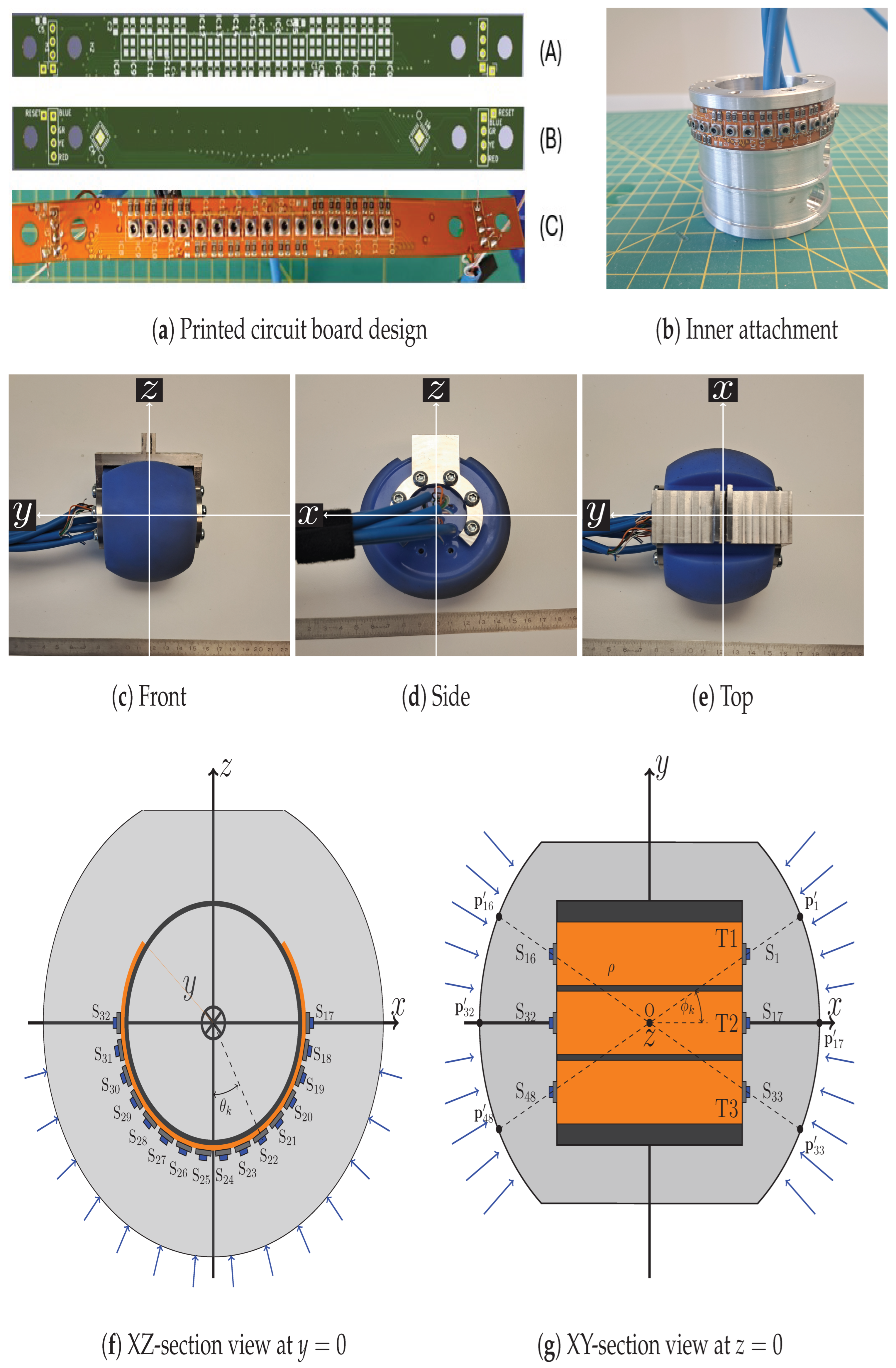
2.1. Tweelie: A Tactile Wheel-Shaped Foot Sensor

The legged robot is equipped with a Tweelie spherical tactile sensor, introduced in a prior work [20]. The Tweelie consists of 48 micro-electromechanical system (MEMS) barometers (MS5840-02BA21, TE Connectivity, Schaffhausen, Switzerland) with a footprint of 3.3 × 3.3 × 1.7 mm (L × W × H). The barometers are distributed over three flexible printed circuit boards (PCBs) of dimensions 150 × 12 mm (L × W). The PCBs are bent along a cylinder, and their position is fixed with bolts such that the barometers are evenly distributed along half the surface of the cylinder. The inner electronics of the sensor foot are depicted in Figure 2.
In order to protect the electronics and to distribute pressure, the inner cylinder is embedded in a cast spherical shape of silicone rubber with hardness shore 15A (Resion). The production procedure is described in more detail in [20]. The resulting sensor is shown in Figure 2c–e. The aluminum cylinder is completely confined within the rubber. The outer aluminum piece is bolted to the inner cylinder and serves as the interface to attach the wheel-shaped sensor to the lower limb of the legged robot. The radius of the cast rubber sphere is 45 mm.
Force applied to the surface of the sphere results in a local deformation, resulting in a pressure change, which is measured by one or more MEMS pressure sensors. The location of each MEMS sensor, fixed by the cylinder geometry and PCB layout, plays an essential role in the force reconstruction model. The location of each sensor element is given in Table 1.
The position of sensor S k on the cylinder is denoted as p k . Consider a ray from the origin O in Figure 2g through each MEMS sensor p k . The point on the surface that intersects each ray with the outer radius of the sphere is denoted as p k . Under the assumption that the pressure sensed by S k originates from a force applied in the neighborhood of p k , a simple force reconstruction model can be defined. The reconstructed 3D force vector F ^ , expressed in the local sensor frame, as shown in Figure 2, is obtained using the data from all 48 sensors:
F ^ = A k p k w k + b
where w k ( 0 , 1 ) is the normalized pressure value for sensor S k , A = diag ( a x x , a y y , a z z ) is a coefficient matrix, and b = b x b y b z T is the bias vector. A and b are obtained using linear regression to calibrate the force model (see Section 3).
This approximate force reconstruction model consists of simple matrix multiplication and addition operations, which are suitable for very fast computation and hence real-time application. A table defining the pressure sensor positions on the cylinder in spherical coordinates is given in Table 1. From this table, the Cartesian positions p k can be easily calculated using
p k = ρ sin ( θ k ) sin ( ϕ k ) cos ( π θ k )
The angles θ and ϕ are defined in Figure 2f,g: θ in the XZ plane and ϕ in the XY plane. The radius ρ of the aluminum cylinder is 24 mm, and the displacement between tracks in the y-direction is 13 mm: ϕ T 1 = atan ( 13 / 24 ) = 28 . 4 ° .

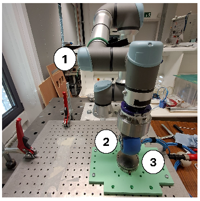
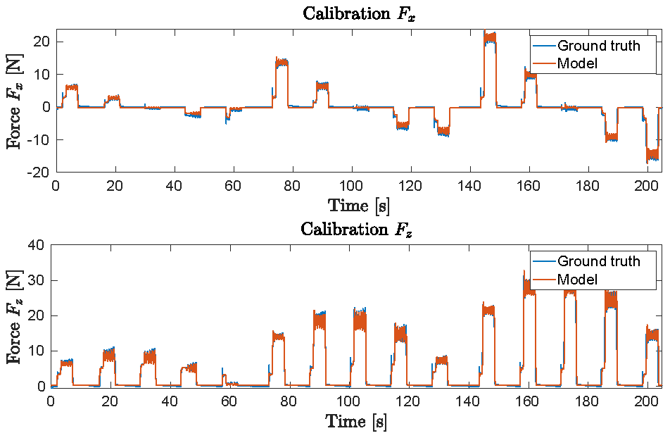
2.2. Data Collection from a Single Tactile Foot

The only communication standard supported by the MEMS sensor is I2C (Inter-Integrated Circuit) [25]. Since each MEMS sensor has the same fixed I2C address, multiplexers (TCA9548A, Texas Instruments, Dallas, TX, USA) are required. The microcontroller communicates with two I2C multiplexers (MUX), which are embedded in the flexible PCB inside the Tweelie sensor. Thus, one microcontroller interfaces with 16 individual MEMS pressure sensors.
It is impractical to directly interface a PC with many I2C sensors, due to both the limited number of serial interfaces and the limited allowable cable distance. This is the reason why an additional microcontroller is used. The sensor data are then translated by the microcontroller into a UDP message and transmitted over an IP network to the control PC. The UDP message consists of an array of 16 pressure values, sampled and transmitted at a fixed frequency of 25 Hz.
A vertical stack of three interface boards with microcontrollers is used to collect the data from one Tweelie sensor. The custom-designed interface board houses the Teensy 4.1 microcontroller, provides power (+5V DC) among the stack, and exposes two I2C channels (RJ12 interface) and one network channel (RJ45 interface). The interface board has a physical footprint of 80 × 53 mm.

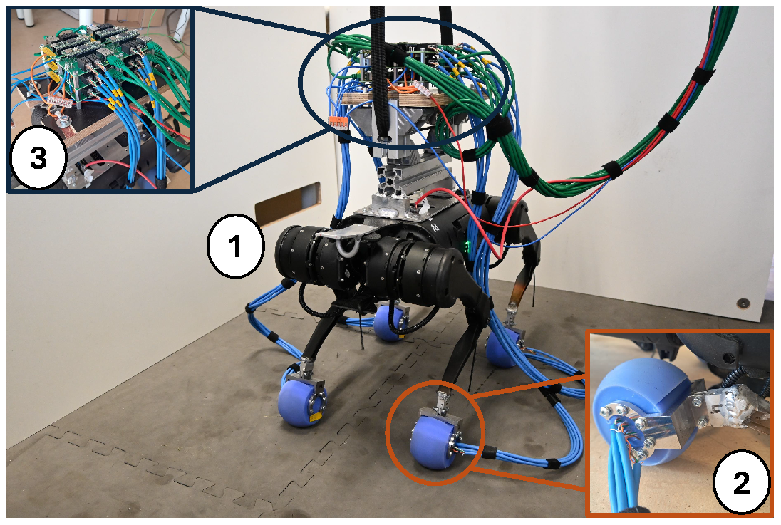
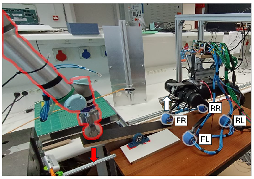
2.3. Integration of Tactile Feet with the Unitree A1 Legged Robot

The Unitree A1 quadruped robot is modified and equipped with four custom tactile sensor feet from Tweelie. An aluminum interface cube is welded to the lower limb of each leg (detail 2 of Figure 1). The outer aluminum piece of the sensor can be firmly attached to this interface with a threaded M4 bolt and nuts. In addition, the design of the sensor enables attachment to the leg of a standard Unitree Go1 robot, as the design of its feet is interchangeable. On the topside of the robot, twelve microcontrollers are attached (detail 3 of Figure 1), stacked in four groups of three, to allow data capture from the installed tactile feet. The weight of this payload amounts to 2.55 kg, and it is attached to the top of the robot base.
Due to the usage of custom feet, the robot API provided by the manufacturer can no longer provide high-level control, including walking behaviors, due to reliance on feedback from the standard feet (binary in/out of contact signal). Instead, only low-level control is available, which exposes the 12 individual servo actuators in the joints. We implement a custom trajectory generator based on the robotoc library [26], which performs model predictive control (MPC) for legged locomotion. A finite-state machine selects high-level commands, such as walking forward or backward, or turning left or right, which are converted into the desired motion trajectories. The MPC then generates joint-space trajectories consisting of position, velocity, and feedforward torque profiles for each joint. These trajectories are recorded offline and later used as reference setpoints in the low-level proportional–derivative (PD) controller (see Section 4) to actuate the physical robot. This approach enables the legged robot (with custom feet) to traverse horizontal terrain in all directions, as demonstrated in [17].

3. Fast GRF Reconstruction Using Tactile Sensor Data

In Section 2, the tactile sensor hardware and the ground reaction force reconstruction model were described. In this section, we introduce the calibration procedure and setup used to fit the model parameters from Equation (1). The experimental setup (shown in Figure 3) involved attaching the tactile sensor to the end effector of a UR5e collaborative robot arm, which was precisely controlled to apply various forces onto a force–torque sensor (Axia 80, ATI Industrial Automation). Data collection was systematically performed at different pitch orientations (−45°, −20°, 0°, +20°, +45°) and roll orientations (−20°, −10°, 0°, +10°, +20°), each repeated multiple times with different forces. Linear regression was used to obtain the best values for A and b for each of the four sensors (denoted as TW1, TW2, TW3, and TW4). In addition, k-fold cross-validation (with k = 5 ) was used to ensure that the force reconstruction model was sufficiently general. The UR5e robot is also used in the balance experiment in Section 5.
The main results reported in Table 2 provide insights into the model’s performance. First, minimal variance is observed due to the k-fold cross-validation within each sensor (intra-sensor variance), suggesting robust generalization and limited overfitting in the linear model. The effectiveness of the linear model is visually supported by Figure 4, which depicts the force reconstruction for sensor TW1 as a representative example. Conversely, notable variance exists between different sensors (inter-sensor variance), emphasizing the necessity of calibrating individual ( A and b ) parameters per sensor to achieve optimal accuracy. This variance between sensors is mainly attributed to manufacturing variability, particularly in the silicone rubber encapsulation, and inherent variations in MEMS pressure sensor elements. After calibration, we obtained a performant 3D force reconstruction method using tactile data, able to sense forces from different directions.

4. Tactile Admittance Control

Zelenak et al. argued that velocity-controlled robots offer superior compliance and robustness in unstructured environments compared to position- or torque-controlled robots [27]. This motivates the use of velocity-based admittance control, yielding smoother and safer contact behavior during ground interaction. We further draw inspiration from the hybrid force and position control of Palejiya and Tanner [28]. Their control strategy switches between velocity-based motion in free space and force-based regulation during contact. This is highly relevant to our method, where tactile events trigger mode switching between free motion and contact interaction, and a force controller shapes leg behavior during contact using a similar hybrid structure. In this work, we use the definition of admittance control as introduced in [22]:
v d = v d , 0 + Y ( F )
The velocity control setpoint v d is composed of a reference velocity setpoint v d , 0 and an admittance term Y ( F ) (a linear or non-linear mapping from force to velocity).
Consider a leg of the quadruped robot, which consists of a kinematic chain with three revolute actuated joints. We implement admittance control at the leg level, as shown in the schematic in Figure 5. The kinematic chain of one leg starts at the base center of mass (CoM) and ends at the foot. The joints are servo PD-controlled with torque feedforward. The control effort τ is calculated as [29]
τ = K p ( q d q ) + K v ( q ˙ d q ˙ ) + τ ff
where the subscript index d indicates the desired value (setpoints).
Velocity-based admittance control is achieved by allowing the external measured force F ^ to influence the setpoint of the velocity part:
q ˙ d = q ˙ d , 0 + Y ( F ^ )
where q ˙ d , 0 is the nominal desired joint velocity, obtained from the trajectory planner, and Y ( F ^ ) is the velocity admittance control output. As shown in the schematic Figure 5a, the admittance controller Y has three inputs:
  • F ^ : The estimated force vector provided by the tactile foot sensor and model.
  • F d , x d : The desired force and Cartesian position of the foot, provided by the trajectory planner.
  • q : The joint position of the leg, provided by the robot state. From the joint position, the Cartesian position, x , of the leg is calculated using the forward kinematics function, denoted as f k in the diagram.
The control dynamic equation for the virtual displacement is given by
M x ¨ a = ( F ^ F d ) D x ˙ a K ( x x d )
where M , D , and K R 3 × 3 represent the virtual inertia, damping, and spring constant of the controller.
The velocity admittance controller is implemented as a hybrid mass-spring-damper system with two reference positions: x , the actual Cartesian position of the leg, and x a , a virtual displacement. The virtual acceleration x ¨ a is driven by the force difference ( F ^ F d ) , a damping term D x ˙ a , and the spring force K ( x x d ) . Note that the spring force is not dependent on the virtual displacement x a ; hence, the actual virtual displacement is irrelevant for the control output.
The virtual acceleration x ¨ a is integrated using forward Euler with timestep Δ t and then bounded using a threshold mechanism to obtain the virtual velocity x ˙ a :
x ˙ a ( k ) = Threshold ( x ˙ a ( k 1 ) + x ¨ a ( k ) Δ t , x t h )
Threshold ( z , x th ) = sign ( z i ) x th , i if | z i | > x th , i , z i if | z i | x th , i
Thresholding allows compliance to be enabled or disabled per Cartesian direction. Setting a threshold to zero effectively disables compliance along that direction. The velocity is transformed to joint space using the inverse Jacobian, which is the output of the admittance control:
Y ( F ^ ) = q ˙ a = J 1 ( q ) x ˙ a
For descriptions of the forward kinematic function f k and the Jacobian J , refer to Appendix A.
The admittance control dynamics behave intuitively. For example, a larger-than-desired upward (z-direction) force results in a large z-component for x ˙ a , which causes the robot (through velocity control) to move upward (i.e., being compliant with the force). This, in turn, causes a discrepancy ( x x d ), which counteracts like a spring against the driving force. In addition, position deviations cause position-based control actions in the servo PD. As soon as the force approaches the equilibrium ( F ^ = F d ), the spring force drives the end effector back to the desired position x d and x ˙ a to zero.
The schematic depicted in Figure 5b shows how the admittance control is embedded in the overall control structure of the legged robot. The trajectory planner gives setpoints to the PD control and admittance control. This control utilizes the tactile feedback provided by the force model.
A note about frequencies: Servo PD control sends torque commands to the robot and receives its state at a 500 Hz frequency. The force reconstruction model operates at 25 Hz. Hence, the force input to the admittance control is submitted at 25 Hz as well. This is indicated in blue in Figure 5b. Given that typical legged locomotion gaits have a step frequency below 3 Hz, we consider the data acquisition frequency of 25 Hz sufficient for the intended application of locomotion.
Conventional admittance or impedance control methods are typically sensorless, relying solely on proprioceptive measurements such as joint encoders, motor current readings, and inertial measurements from onboard IMUs. However, implementing such controllers requires an accurate actuator model to relate motor currents to joint torques, a dynamic model to propagate these torques through the robot’s multibody structure, and a contact model to estimate the resulting ground reaction forces. On commercial platforms such as the Unitree A1, some hardware specifications, such as the motor current constant, are not fully disclosed, hindering accurate modeling. Moreover, contact models often require an estimate of the contact normal direction, which is non-trivial to obtain during operation.
In contrast, the proposed tactile admittance control approach eliminates the need for these modeling assumptions by directly measuring contact forces using soft, embedded barometric sensors in the feet. As a result, the control law is independent of the actuation parameters, link inertias, and contact normal estimation. This sensor-based approach simplifies implementation and improves portability, enabling the same control strategy to be deployed across a range of legged robots regardless of their hardware configurations.

5. Results

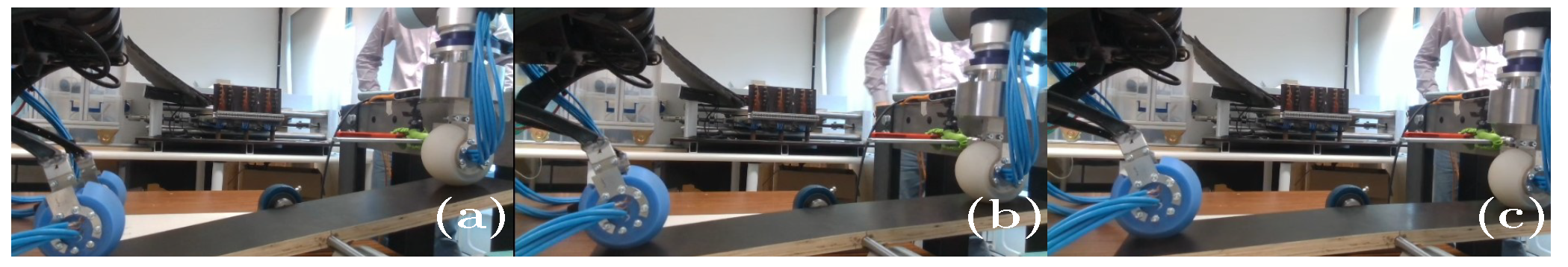
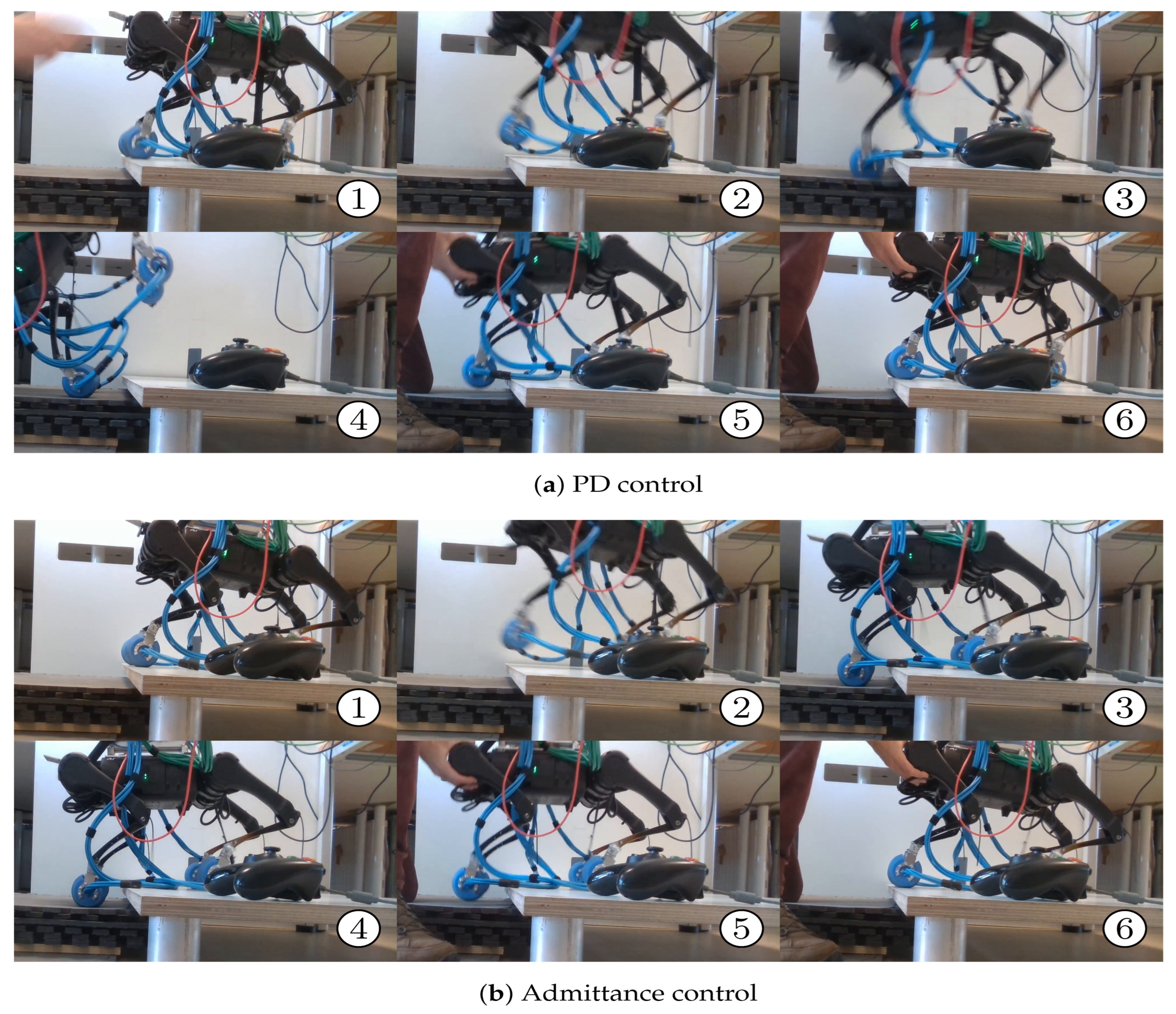
5.1. Static Balance Experiment on a Beam Using Admittance Control

The integration of tactile feedback into the robot control is of practical importance for legged locomotion, particularly for handling unexpected disturbances such as early or late foot touchdown, which can cause significant deviations in ground reaction forces. To evaluate the effect of tactile-based admittance control, this section presents an experiment designed to emulate the realistic disturbances encountered during locomotion within a controlled setting. The legged robot is resting with the front right (FR) foot on the beam of a lever. The beam is made from laminated wood material and has dimensions 560 × 120 × 18 mm (L × W × H). The fulcrum is a steel rod with a diameter of 12 mm supported by a bearing house.
A fixed-base UR5e robot pushes its tool center point (TCP) downward on the opposite side of the fulcrum, disturbing the legged robot, which must maintain its balance. The UR5e is position-controlled to ensure consistent and repeatable actuation of the beam. As the pusher presses down, the front right (FR) leg of the quadruped is lifted up, and the center of mass shifts toward its diagonal opposite leg, the rear left (RL) leg, causing a disturbance for the legged robot. The setup is shown in Figure 6, and a snapshot of the experiment is depicted in Figure 7.
In order to assess the balancing capability of the proposed admittance controller, the experiment was executed once under the baseline PD control, which commanded a static pose for the robot while disturbed, and once with the admittance control enabled, with the experimental parameters given in Table 3. For each joint, the servo gains of the motor control (Equation (4)) were fixed at K p = 80 and K v = 5 , which were selected during manual tuning. The applied force, registered ground reaction forces, and joint position states were compared. As indicated in the table, the threshold value x ˙ t h was zero in its first two components, meaning the legs were not compliant in the (body) x- and y-directions, only in the z-direction. In this experiment, we deliberately restricted the admittance controller to act only along the vertical (z) axis. This decision was made for two reasons. First, the external disturbance introduced during the balance experiment (i.e., an upward force acting through the balance) primarily perturbed the vertical direction. Second, constraining the admittance behavior simplified the comparative analysis with the baseline PD control. Thus, we can attribute the observed changes specifically to the enabled admittance in the z-axis in each leg. While this represents a basic use case, the proposed framework is naturally extendable to the x- and y-directions. Such extensions are the subject of future work focused on multi-directional tactile compliance.
In Figure 8, the applied disturbance force (as measured by the UR5e robot) and the TCP height are displayed. The disturbance was repeated four times. We note that the mean force while the end effector was down was 72 N with the PD control active (blue line), whereas it was only 55 N with the admittance control (red line, denoted as ADM), indicating a 23% reduction for the same displacement. This was also observed in the ground reaction forces (GRF) measured by the tactile sensor, as shown in Figure 9.
Looking at the FR leg, during disturbances, the GRF was consistently lower with admittance control. When the pusher moved upward, the robot rebalanced, and the GRF oscillated around the desired 30 N force F d , z . The same observation was made for the FL and RR legs: the force was effectively modulated around the desired force, allowing the robot to improve its balance. We made an interesting observation about the RL GRF. With only the PD control, a large peak force was observed with the disturbance active, above 90 N, as more than half the robot’s weight was effectively transferred to a single leg, potentially overheating the motors of this leg. Without a disturbance force applied, the force remained the largest among all the legs, as the robot was not horizontally aligned but slightly tilted backward and sideways (see the image of the setup in Figure 6). With the admittance control, however, the measured force was significantly reduced, as the other legs actively participated to regulate the force, resulting in a more distributed GRF. It was observed that under the admittance control, the RL GRF remained above its desired setpoint for the entire duration of the experiment. It barely changed, and this behavior can be explained by the heavy loading of this leg, as seen in the baseline scenario, PD control. The peak force on this overloaded leg was reduced from 90 N to 40 N, amounting to a 55% reduction in the peak force, which is clearly visible in the force RL plot in Figure 9.
The observations of the joint positions are plotted in Figure 10. Overall, we noted that the robot assumed significantly different joint-space positions depending on the control mode. The FR leg, which was primarily disturbed, deviated during the force application periods (gray shaded zones). The RL joints exhibited saturation behavior in the HFE joint under PD control and in the KFE joint under admittance control due to the heavy loading on this leg.

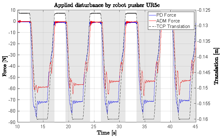
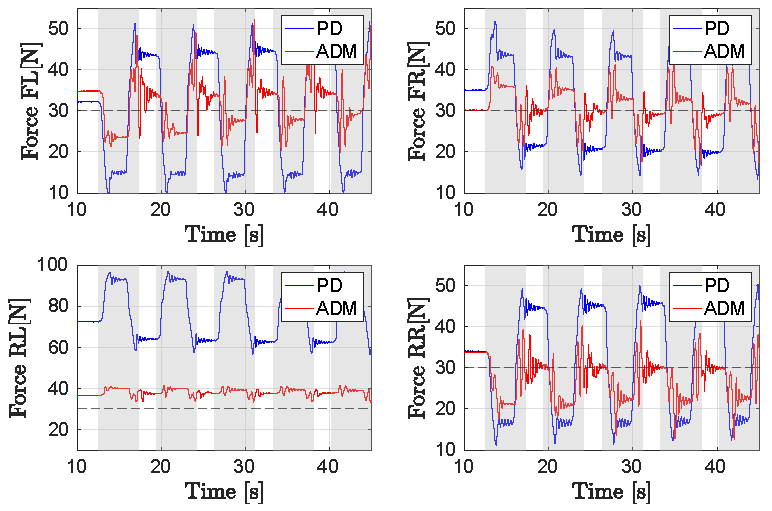
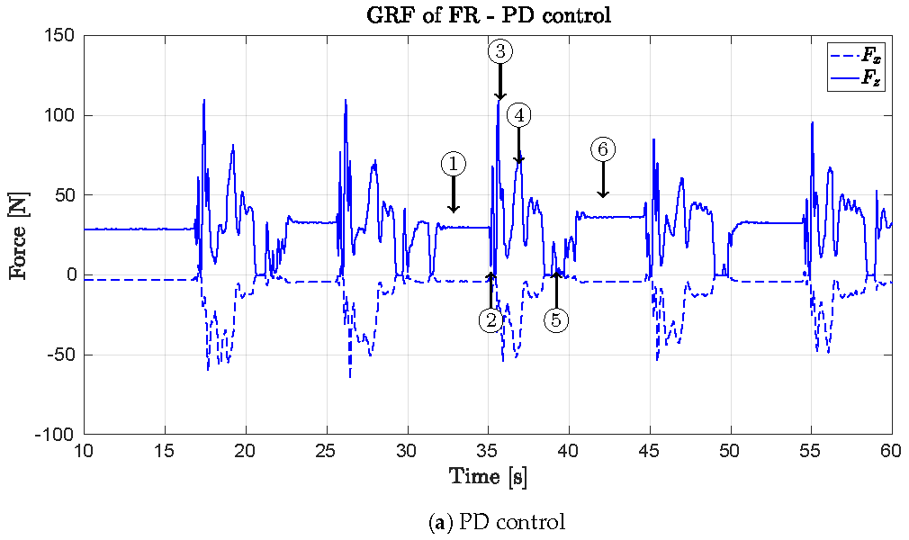
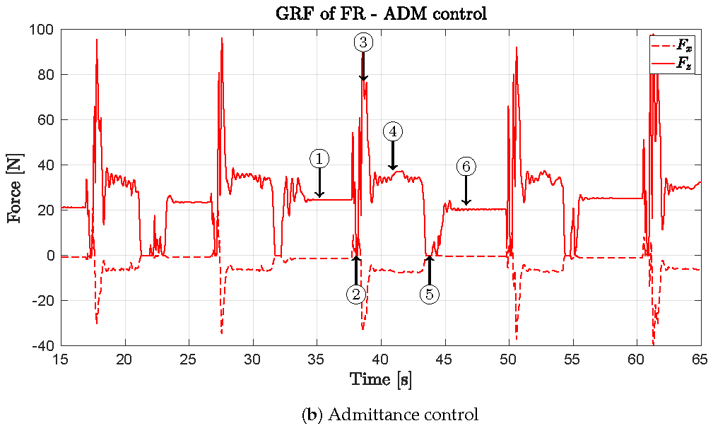
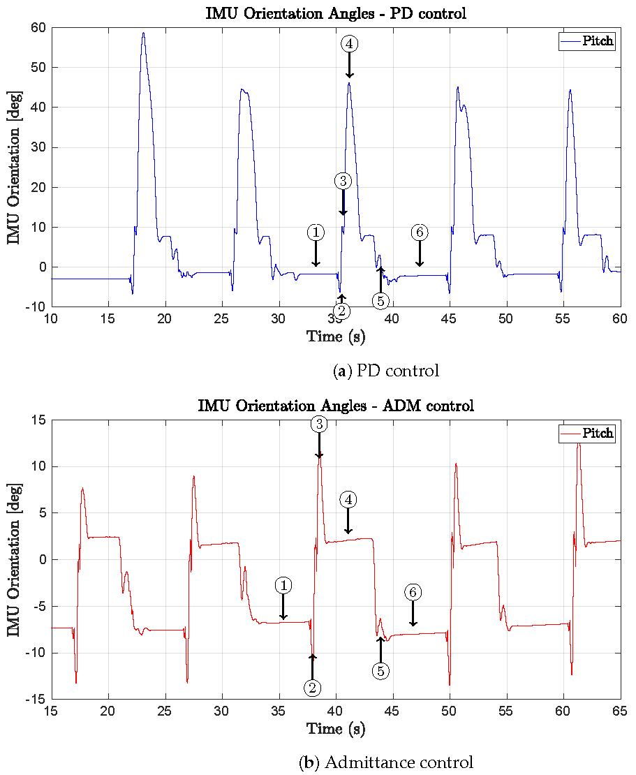
5.2. Dynamic Balance Experiment Using Admittance Control

The legged robot started on an elevated platform (5 cm above the ground), positioned near the edge. The robot was commanded to perform a bound gait, in which both front legs first jumped forward with the rear legs standing, and then both rear legs moved forward with the front legs standing. As the robot moved forward over the edge, it suddenly dropped 5 cm lower with significant forward momentum. The robot needed to maintain balance during locomotion as soon as contact was established. The lower ground floor was composed of soft rubber material to protect the hardware during the experiments.
The admittance control parameters are shown in Table 4. Compared to the settings for the static balance experiment (Table 3), the desired force in the z-direction for the front legs was increased and decreased for the rear legs. The threshold values were increased for all legs, resulting in a larger effect of the admittance control effort. The rest of the parameters remained the same as in the static balance experiment.
A visual representation of the experiment, depicting six frames, is given in Figure 11. As is clear from the snapshots, when comparing Frames 3 and 4 under both control modes, the robot managed to restore balance and mitigate the impact with the tactile admittance control mode enabled. Without the admittance control, the robot tripped and rolled forward, stopped by safety measures. After performing the step with the bound gait, the robot was reset to its original position on the platform by the operator, and the experiment was repeated. Similar to the static balance experiment, the experiment was repeated five times with the admittance control disabled (PD control mode) and enabled (ADM control mode). The observations are valid for the five repetitions.
Reusing the same definitions of the time frames, the force plots for the horizontal F x and vertical F z ground reaction forces for the front right foot are shown in Figure 12, and the pitch angle plot (the rotation about the y-axis) is shown in Figure 13. The data plotted are for the five repeated movements, and a comparison is made between the two control modes. In the pitch angle plot, it can be observed that the admittance control effectively stabilized the robot.
At the start (Frame 1), the robot adopted its nominal pose. Compared to the PD control, the admittance-controlled robot started from a slightly backward-tilted configuration (pitch 7 ° ). As the bounding motion began (Frame 2), the front legs lifted off, and the vertical forces dropped to zero under both conditions. Upon re-establishing contact (Frame 3), the peak touchdown forces were recorded in the front legs, ranging from 90 to 110 N under the PD control and slightly lower under the admittance control. This impact resulted in a forward pitch to ≈10° in both cases.
The key distinction was in the recovery behavior (Frame 4). With the PD control, the front legs showed high-frequency oscillations in the force, and the body rapidly pitched forward, as visible in Frame 4 of Figure 11. In contrast, the admittance control stabilized the force to approximately 30N smoothly and held pitch near 0° demonstrating damped behavior and maintaining balance while holding the base horizontal. When the robot was reset to its initial pose (Frames 5 and 6), both configurations returned to similar states as in Frame 1.

6. Conclusions

This work explored the integration of spherical tactile sensors in the Unitree A1 quadruped robot. These tactile feet offer wide-area sensing coverage and enable direct measurement of ground reaction forces (GRFs), allowing the legged robot to interact with its environment in a compliant way.
A computationally efficient 3D force reconstruction method based on the pressure readings of the MEMS-based tactile sensors was presented. The linear model, calibrated using force–torque measurements, generalized well across sensor orientations, which is essential for locomotion applications. Using spherical tactile feet data, the GRFs could be measured reliably even under high-impact and varying contact scenarios.
Next, we developed a tactile admittance control framework that augments the baseline servo controller by adding an additional velocity command derived from the measured contact forces. This resulted in a hybrid control structure, where motion is shaped by both the planned trajectories and sensed interaction forces. The admittance controller behaves as a virtual mass-spring-damper system, with intuitive parameters that directly influence the robot’s compliance characteristics: mass affects responsiveness, damping governs smoothness, and stiffness enforces deviation limits. This tactile force feedback allows the robot to adapt its foot motion in real time, enabling effective redistribution of contact forces and enhanced stability under external disturbances.
Experimental validation confirmed the effectiveness of this approach. In a static balance experiment on a beam, the tactile admittance control reduced the external disturbance force by 23% and the peak GRFs on the overloaded leg by 55%, demonstrating active force redistribution. In a dynamic jumping-and-landing scenario, the robot stabilized after impact using tactile feedback, while the baseline controller failed to do so.
While promising, the current method was tested in a limited setting, delivering compliance only in the vertical direction with fixed control gains. Extending compliance to multiple axes and enabling online parameter tuning could introduce new applications, with open questions regarding the complexity of stability and control. The long-term mechanical durability of the soft sensor feet also remains to be evaluated. Future work should investigate multi-directional adaptive admittance control, fusion with other sensory modalities (e.g., vision or LiDAR), and prolonged testing under varied terrain and environmental conditions. These enhancements will further support resilient and autonomous locomotion in complex, real-world settings.

Author Contributions

The contributions of the individual authors can be summarized as follows. Conceptualization, T.V.H., A.C. and G.C.; Methodology, T.V.H.; Software, T.V.H.; Validation, T.V.H.; Formal analysis, T.V.H.; Investigation, T.V.H.; Resources, G.C.; Data curation, T.V.H.; Writing—original draft, T.V.H.; Writing—review and editing, A.C. and G.C.; Visualization, T.V.H.; Supervision, A.C. and G.C.; Project administration, G.C.; Funding acquisition, A.C. and G.C. All authors have read and agreed to the published version of the manuscript.

Funding

This research was funded by Research Foundation–Flanders grant number 12Z4722N.

Data Availability Statement

Data are available on request due to restrictions.

Conflicts of Interest

The authors declare no conflicts of interest. The funders had no role in the design of the study; in the collection, analyses, or interpretation of data; in the writing of the manuscript; or in the decision to publish the results.

Abbreviations

The following abbreviations are used in this manuscript:
MEMSMicro-Electromechanical System
IMUInertial Measurement Unit
PCBPrinted Circuit Board
PD ControlProportional–Derivative Control
I2CInter-integrated Circuit
MUXMultiplexer
IPInternet Protocol
UDPUser Datagram Protocol
APIApplication Program Interface
MPCModel Predicitve Control
CoMCenter of Mass
FRFront Right (leg)
FLFront Left (leg)
RRRear Right (leg)
RLRear Left (leg)
GRFGround Reaction Forces
HAAHip Abduction Adduction
HFEHip Flexion Extension
KFEKnee Flexion Extension
ADMAdmittance Control Mode

Appendix A. Kinematic Description of a Single Leg of the Unitree A1 Quadruped Robot

A kinematic chain describes a series of linked bodies (rigid links connected by joints) used to model robotic manipulators. The Unitree A1 quadruped robot has a leg consisting of three revolute joints: hip roll (rotation about the x-axis), hip pitch (rotation about the y-axis), and knee pitch (rotation about the y-axis). To analyze its motion, we use homogeneous transformation matrices to describe the relationship between different coordinate frames along the kinematic chain.
A homogeneous transformation matrix T j i represents the pose (position and orientation) of frame j relative to frame i. It has the general form
T j i = R j i p j i 0 1 × 3 1 R 4 × 4
where R j i S O ( 3 ) is a rotation matrix belonging to the special orthogonal group and p j i R 3 is the translation vector.
The kinematic structure of a single leg follows the sequence
T end = T 1 0 ( q 0 ) T 2 1 ( q 1 ) T 3 2 ( q 2 ) T 4 3
where q 0 is the HAA (hip abduction adduction) angle (rotation about the x-axis), q 1 is the HFE (hip flexion extension) angle (rotation about the y-axis), and q 2 is the KFE (knee flexion extension) angle (rotation about the y-axis).
Note that T 4 3 is a static transform from the knee joint to the foot (end-effector) frame.
Each transformation consists of a rotation matrix and a translation vector. Combining the transformations results in the end-effector frame, which defines the forward kinematics function:
T end = R end p end 0 1 × 3 1 R 4 × 4
where p end is the Cartesian position of the foot in the base frame. This transformation matrix T end defines the forward kinematics function f k , as it maps the joint state q 0 ; q 1 ; q 2 T to the Cartesian position p end .
The Jacobian matrix  J ( q ) relates the joint velocities q ˙ to the linear and angular velocities of the end effector:
x ˙ = J ( q ) q ˙
where x ˙ = [ v end , ω end ] T R 6 × 1 is the Cartesian velocity of the foot, q ˙ R 3 × 1 = [ q ˙ 0 , q ˙ 1 , q ˙ 2 ] T is the joint velocity vector, and J ( q ) R 6 × 3 the joint-dependent Jacobian matrix.
Using the decomposition properties of forward kinematics, the time derivative of the transformation matrix follows:
d d t T end = S 1 T 1 T 2 T 3 q ˙ 1 + T 1 S 2 T 2 T 3 q ˙ 2 + T 1 T 2 S 3 T 3 q ˙ 3
where each S i is the motion screw for joint i and e ^ i is the basis vector:
S i = e ^ i × ( p end p i ) e ^ i
Now, in order to calculate the columns of the Jacobian, which signify the effect each joint has on the end-effector velocity, an intermediate step involves calculating the transformation frames from the base to each joint origin:
  • T 1 0 = T 1 0 ( q 0 ) , the transform from the base to the HAA joint.
  • T 2 0 = T 2 1 ( q 1 ) T 1 0 , the transform from the base to the HFE joint.
  • T 3 0 = T 3 2 ( q 2 ) T 2 1 , the transform from the base to the KFE joint.
We use these to extract the rotation axes z i and the joint positions p i :
  • z 0 (HAA rotation, x-axis rotation) is R : , 1 , the first column of T 0 1 .
  • z 1 (HFE rotation, y-axis rotation) is R : , 2 of T 0 2 .
  • z 2 (KFE rotation, y-axis rotation) is R : , 2 of T 0 3 .
  • p 0 (HAA position) is p of T 0 1 .
  • p 1 (HFE position) is p of T 0 2 .
  • p 2 (KFE position) is p of T 0 3 .
Each column of the Jacobian is computed as
J i = z i × ( p end p i ) z i
where p i is the position of joint i in the world frame.
Thus, the full Jacobian is
J ( q ) = z 0 × ( p end p 0 ) z 1 × ( p end p 1 ) z 2 × ( p end p 2 ) z 0 z 1 z 2
This 6 × 3 matrix maps the joint velocities q ˙ to the Cartesian velocities x ˙ .

References

  1. Cheng, X.; Kumar, A.; Pathak, D. Legs as Manipulator: Pushing Quadrupedal Agility Beyond Locomotion. In Proceedings of the 2023 IEEE International Conference on Robotics and Automation (ICRA), London, UK, 29 May–2 June 2023; pp. 5106–5112. [Google Scholar] [CrossRef]
  2. Hoeller, D.; Rudin, N.; Sako, D.; Hutter, M. ANYmal parkour: Learning agile navigation for quadrupedal robots. Sci. Robot. 2024, 9, eadi7566. [Google Scholar] [CrossRef] [PubMed]
  3. Arm, P.; Mittal, M.; Kolvenbach, H.; Hutter, M. Pedipulate: Enabling Manipulation Skills using a Quadruped Robot’s Leg. In Proceedings of the 2024 IEEE International Conference on Robotics and Automation (ICRA), Yokohama, Japan, 13–17 May 2024; pp. 5717–5723. [Google Scholar] [CrossRef]
  4. Majithia, A.; Shah, D.; Dave, J.; Kumar, A.; Rathee, S.; Dogra, N.; Vishwanathah, H.M.; Chiniwar, D.S.; Hiremath, S. Design, motions, capabilities, and applications of quadruped robots: A comprehensive review. Front. Mech. Eng. 2024, 10, 1448681. [Google Scholar] [CrossRef]
  5. Jang, Y.; Seol, W.; Lee, K.; Kim, K.S.; Kim, S. Development of quadruped robot for inspection of underground pipelines in nuclear power plants. Electron. Lett. 2022, 58, 234–236. [Google Scholar] [CrossRef]
  6. Gehring, C.; Fankhauser, P.; Isler, L.; Diethelm, R.; Bachmann, S.; Potz, M.; Gerstenberg, L.; Hutter, M. ANYmal in the Field: Solving Industrial Inspection of an Offshore HVDC Platform with a Quadrupedal Robot. In Field and Service Robotics; Ishigami, G., Yoshida, K., Eds.; Springer: Singapore, 2021; pp. 247–260. [Google Scholar]
  7. Pencelli, M.; Bonacchi, L.B.; Fiorucci, M.; Schillaci, G.; Youssef, A.; Politano, A.; Bettini, A.; Porciani, D.; Salusti, L.; Cioncolini, S.; et al. Testing the Robustness of Quadruped Robots for Unmanned Inspection Activities in the Energy Industry. In Proceedings of the IPTC International Petroleum Technology Conference, Dhahran, Saudi Arabia, 13 February 2024. [Google Scholar] [CrossRef]
  8. Cheng, Y.; Liu, H.; Pan, G.; Liu, H.; Ye, L. Quadruped robot traversing 3D complex environments with limited perception. In Proceedings of the 2024 IEEE/RSJ International Conference on Intelligent Robots and Systems (IROS), Abu Dhabi, United Arab Emirates, 14–18 October 2024; pp. 9074–9081. [Google Scholar] [CrossRef]
  9. Barasuol, V.; Buchli, J.; Semini, C.; Frigerio, M.; De Pieri, E.R.; Caldwell, D.G. A reactive controller framework for quadrupedal locomotion on challenging terrain. In Proceedings of the 2013 IEEE International Conference on Robotics and Automation, Karlsruhe, Germany, 6–10 May 2013; pp. 2554–2561. [Google Scholar] [CrossRef]
  10. Bledt, G.; Powell, M.J.; Katz, B.; Di Carlo, J.; Wensing, P.M.; Kim, S. MIT Cheetah 3: Design and Control of a Robust, Dynamic Quadruped Robot. In Proceedings of the 2018 IEEE/RSJ International Conference on Intelligent Robots and Systems (IROS), Madrid, Spain, 1–5 October 2018; pp. 2245–2252. [Google Scholar] [CrossRef]
  11. Aractingi, M.; Léziart, P.A.; Flayols, T.; Perez, J.; Silander, T.; Souères, P. Controlling the Solo12 quadruped robot with deep reinforcement learning. Sci. Rep. 2023, 13, 11945. [Google Scholar] [CrossRef]
  12. Miki, T.; Lee, J.; Hwangbo, J.; Wellhausen, L.; Koltun, V.; Hutter, M. Learning robust perceptive locomotion for quadrupedal robots in the wild. Sci. Robot. 2022, 7, eabk2822. [Google Scholar] [CrossRef] [PubMed]
  13. Gu, S.; Meng, F.; Liu, B.; Zhang, Z.; Sun, N.; Wang, M. Stability Control of Quadruped Robot Based on Active State Adjustment. Biomimetics 2023, 8, 112. [Google Scholar] [CrossRef] [PubMed]
  14. Shi, G.; Yao, C.; Liu, X.; Zhao, Y.; Zhu, Z.; Jia, Z. Foot Vision: A Vision-Based Multi-Functional Sensorized Foot for Quadruped Robots. IEEE Robot. Autom. Lett. 2024, 9, 6720–6727. [Google Scholar] [CrossRef]
  15. Stone, E.A.; Lepora, N.F.; Barton, D.A.W. Walking on TacTip toes: A tactile sensing foot for walking robots. In Proceedings of the 2020 IEEE/RSJ International Conference on Intelligent Robots and Systems (IROS), Las Vegas, NV, USA, 24 October 2020–24 January 2021; pp. 9869–9875. [Google Scholar]
  16. Zhang, G.; Du, Y.; Zhang, Y.; Wang, M.Y. A Tactile Sensing Foot for Single Robot Leg Stabilization. In Proceedings of the 2021 IEEE International Conference on Robotics and Automation (ICRA), Xi’an, China, 30 May–5 June 2021; pp. 14076–14082. [Google Scholar] [CrossRef]
  17. Van Hauwermeiren, T.; Sianov, A.; Coene, A.; Crevecoeur, G. Integrated Barometric Pressure Sensors on Legged Robots for Enhanced Tactile Exploration of Edges. IEEE Robot. Autom. Lett. 2024, 9, 6368–6375. [Google Scholar] [CrossRef]
  18. Sun, C.; Chen, Z.; Ye, S.; Lin, J.; Shi, W.; Li, B.; Teng, F.; Li, X.; Zhang, A. Highly-time-resolved FMCW LiDAR with synchronously-nonlinearity-corrected acquisition for dynamic locomotion. Opt. Express 2023, 31, 7774–7788. [Google Scholar] [CrossRef] [PubMed]
  19. Bledt, G.; Wensing, P.M.; Ingersoll, S.; Kim, S. Contact Model Fusion for Event-Based Locomotion in Unstructured Terrains. In Proceedings of the 2018 IEEE International Conference on Robotics and Automation (ICRA), Brisbane, QLD, Australia, 21–25 May 2018; pp. 4399–4406. [Google Scholar] [CrossRef]
  20. Van Hauwermeiren, T.; Sianov, A.; Coene, A.; Crevecoeur, G. Tweelie: Tactile Wheel-Shaped Sensor for Force Reconstruction and Localization Over Curved Spherical Surface. IEEE Sens. Lett. 2025, 9, 6003004. [Google Scholar] [CrossRef]
  21. Ott, C.; Mukherjee, R.; Nakamura, Y. Unified Impedance and Admittance Control. In Proceedings of the 2010 IEEE International Conference on Robotics and Automation, Anchorage, AK, USA, 3–7 May 2010; pp. 554–561. [Google Scholar] [CrossRef]
  22. Schimmels, J.; Peshkin, M. Admittance matrix design for force-guided assembly. IEEE Trans. Robot. Autom. 1992, 8, 213–227. [Google Scholar] [CrossRef]
  23. Cong, Z.; Honglei, A.; Wu, C.; Lang, L.; Wei, Q.; Hongxu, M. Contact Force Estimation Method of Legged-Robot and Its Application in Impedance Control. IEEE Access 2020, 8, 161175–161187. [Google Scholar] [CrossRef]
  24. Jin, B.; Sun, C.; Zhang, A.; Ding, N.; Lin, J.; Deng, G.; Zhu, Z.; Sun, Z. Joint Torque Estimation toward Dynamic and Compliant Control for Gear-Driven Torque Sensorless Quadruped Robot. In Proceedings of the 2019 IEEE/RSJ International Conference on Intelligent Robots and Systems (IROS), Macau, China, 3–8 November 2019; pp. 4630–4637. [Google Scholar] [CrossRef]
  25. NXP Semiconductors. UM10204 I2C-Bus Specification and User Manual. 2014. Rev. 6. Available online: https://www.nxp.com/docs/en/user-guide/UM10204.pdf (accessed on 15 March 2025).
  26. Katayama, S.; Ohtsuka, T. Lifted contact dynamics for efficient optimal control of rigid body systems with contacts. In Proceedings of the 2022 IEEE/RSJ International Conference on Intelligent Robots and Systems (IROS 2022), Kyoto, Japan, 23–27 October 2022. [Google Scholar]
  27. Karan, F.S.N.; Chakraborty, S. The Advantages of Velocity Control for Reactive Robot Motion. In Proceedings of the Dynamic Systems and Control Conference, Columbus, OH, USA, 28–30 October 2015; Volume 3. [Google Scholar] [CrossRef]
  28. Palejiya, D.; Tanner, H.G. Hybrid velocity/force control for robot navigation in compliant unknown environments. Robotica 2006, 24, 745–758. [Google Scholar] [CrossRef]
  29. Spong, M.W.; Hutchinson, S.; Vidyasagar, M. Robot Modeling and Control; John Wiley & Sons: Hoboken, NJ, USA, 2006. [Google Scholar]
Figure 1. 1: Unitree A1 quadruped legged robot, fitted with four custom Tweelie tactile feet, with data acquisition hardware on top. 2: Detailed view of tactile foot attachment. 3: Data acquisition using twelve Teensy 4.1 microcontrollers (PJRC, Sherwood, OR, USA).
Machines 13 00426 g001
Figure 2. (a) Tweelie electronics, showing the design of the PCB topside (A), the PCB bottom (B), and an image of the soldered topside (C). (b) Attachment of the flexible PCB on the inner aluminum cylinder. In the actual sensor, three flexible PCBs are attached. (ce) Different views of the Tweelie tactile sensor foot. (f) Schematic of the inner electronics and outer elastomer shape: XZ-section view and definition of θ , and (g) XY-section view and definition of ϕ . The blue arrows denote the area where forces can be sensed. The figure is adapted from [20] with permission.
Machines 13 00426 g002
Figure 3. Experimental setup used to calibrate the force model of the tactile sensor. The tactile foot (2) is attached to the end effector of the UR5e cobot (1) and makes contact with the ATI force–torque sensor (3).
Machines 13 00426 g003
Figure 4. Comparison over time of measured and reconstructed ground reaction forces (GRFs) in the x- and z-directions for sensor TW1 after calibration using the parameters in Table 2.
Machines 13 00426 g004
Figure 5. (a) Block diagram of tactile admittance controller Y takes as input the estimated force F ^ , the desired force F d , the desired Cartesian position of the foot x d , and the joint state q . The output is a velocity command in joint space q ˙ a , while the control dynamics (Equation (6)) are in Cartesian space. (b) Overview of a robot leg control structure with the admittance controller embedded in the loop. The black control signals are transmitted at 500 Hz, the blue signals are transmitted at 25 Hz.
Machines 13 00426 g005
Figure 6. Balance experiment: The fixed-base UR5e robot (outlined in transparent red) is position-controlled to push downward on a beam (black multiplex). At the other side of the beam, the balance of the Unitree A1 legged robot with tactile feet is disturbed as the front right (FR, outlined in transparent white) foot is pushed upward by the lever device. The disturbance also results in force redistribution on the other feet (outlined in transparent white): front left (FL) leg, rear right (RR) leg, and rear left (RL) leg.
Machines 13 00426 g006
Figure 7. Snapshot of the beam disturbance experiment. (a) Initial state with TCP at maximum height. (b) Beam being pushed down. (c) TCP at minimum, 35 mm downward movement, causing the disturbance.
Machines 13 00426 g007
Figure 8. Balance experiment: A controlled disturbance is applied by the UR5e, repeated four times. Blue line: applied force when the quadruped is proportional–derivative-controlled (PD). Red line: applied force when the quadruped robot is admittance-controlled (ADM). Black dashed line: tool center point (TCP) of the UR5e robot’s z-position. The gray dashed areas in the plot indicate the times when the TCP is below the upper reference position and is thus applying a disturbance.
Machines 13 00426 g008
Figure 9. Measured ground reaction forces in the z-direction during the balance experiment, reconstructed from tactile sensor data. Each subplot corresponds to one leg of the robot (FR, FL, RR, and RL). The blue line represents the standard PD control, while the red line shows the response with the admittance control active. The desired force F d is plotted with a dashed line. The admittance control reduces the peak forces, especially on the RL leg, and leads to a more balanced redistribution of the load across all feet during external disturbances.
Machines 13 00426 g009
Figure 10. Measured joint positions of each leg during the balance experiment under the PD control (blue) and the tactile admittance control (red). Each subplot shows the evolution of the hip abduction (HAA), hip flexion (HFE), and knee flexion (KFE) joints. The admittance control leads to distinct joint behaviors, particularly in the disturbed FR leg and the heavily loaded RL leg.
Machines 13 00426 g010
Figure 11. Dynamic balance experiment key frames: (1) Stable standing near the edge of the platform. (2) Front legs lifted. (3) Impact on the ground. (4) After impact. (5) Reset to the original position, front legs lifted. (6) Original position.
Machines 13 00426 g011
Figure 12. Dynamic balance experiment force plots of the FR foot, with the 6-frame sequence of Figure 11 indicated. Showing the plot of F x and F z in the body frame. (a) PD control. (b) Admittance control.
Machines 13 00426 g012aMachines 13 00426 g012b
Figure 13. Dynamic balance experiment: Pitch angle (IMU measurement) of the robot, with the 6-frame sequence from Figure 11 indicated. (a) PD control. (b) Admittance control.
Machines 13 00426 g013
Table 1. Positions of the MEMS sensor on the PCB tracks and orientation in the sensor assembly.
Track 1 (T1) θ [°] ϕ [°]Track 2 (T2) θ [°] ϕ [°]Track 3 (T3) θ [°] ϕ [°]
S19028.4S17900S3390−28.4
S27828.4S18780S3478−28.4
S36628.4S19660S3566−28.4
S45428.4S20540S3654−28.4
S54228.4S21420S3742−28.4
S63028.4S22300S3830−28.4
S71828.4S23180S3918−28.4
S8628.4S2460S406−28.4
S9−628.4S25−60S41−6−28.4
S10−1828.4S26−180S42−18−28.4
S11−3028.4S27−300S43−30−28.4
S12−4228.4S28−420S44−42−28.4
S13−5428.4S29−540S45−54−28.4
S14−6628.4S30−660S46−66−28.4
S15−7828.4S31−780S47−78−28.4
S16−9028.4S32−900S48−90−28.4
Table 2. Cross-validated force reconstruction parameters and metrics for each Tweelie sensor (mean ± std over 5 folds).
SensorAxisA [-]b [-]RMSE [-] R 2 [-]
TW1Fx11.97 ± 0.030.00 ± 0.0040.13 ± 0.010.98 ± 0.004
Fy11.91 ± 0.030.15 ± 0.0020.16 ± 0.0080.97 ± 0.002
Fz11.99 ± 0.02−0.18 ± 0.0090.14 ± 0.0080.98 ± 0.002
TW2Fx11.51 ± 0.04−0.60 ± 0.0060.20 ± 0.020.96 ± 0.007
Fy11.24 ± 0.021.26 ± 0.0060.22 ± 0.0070.95 ± 0.003
Fz11.01 ± 0.011.25 ± 0.0080.21 ± 0.020.96 ± 0.007
TW3Fx11.57 ± 0.030.92 ± 0.010.22 ± 0.020.95 ± 0.009
Fy11.75 ± 0.040.17 ± 0.0060.25 ± 0.030.93 ± 0.02
Fz11.66 ± 0.052.42 ± 0.010.23 ± 0.010.95 ± 0.006
TW4Fx11.67 ± 0.02−0.93 ± 0.0070.16 ± 0.010.97 ± 0.003
Fy12.09 ± 0.040.24 ± 0.0040.19 ± 0.010.96 ± 0.004
Fz11.28 ± 0.013.41 ± 0.0070.12 ± 0.0030.99 ± 0.0008
Table 3. Admittance control parameters per leg: front right (FR) leg, front left (FL) leg, rear right (RR), and rear left (RL) leg.
ParameterFRFLRRRL
x d [m](0.18, −0.13, −0.25)(0.18, 0.13, −0.25)(−0.18, −0.13, −0.25)(−0.18, 0.13, −0.25)
F d [N](0, 0, 30)(0, 0, 30)(0, 0, 30)(0, 0, 30)
M [kg]diag (10, 10, 10)diag (10, 10, 10)diag (10, 10, 10)diag (10, 10, 10)
D [Ns/m]diag (1, 1, 1)diag (1, 1, 1)diag (1, 1, 1)diag (1, 1, 1)
K [N/m]diag (10, 10, 10)diag (10, 10, 10)diag (10, 10, 10)diag (10, 10, 10)
x ˙ t h [m/s](0, 0, 0.1)(0, 0, 0.1)(0, 0, 0.1)(0, 0, 0.1)
Table 4. Admittance control parameters during the dynamic balance experiment.
ParameterFRFLRRRL
x d [m](0.18, −0.13, −0.25)(0.18, 0.13, −0.25)(−0.18, −0.13, −0.25)(−0.18, 0.13, −0.25)
F d [N](0, 0, 60)(0, 0, 60)(0, 0, 20)(0, 0, 20)
M [kg]diag (10, 10, 10)diag (10, 10, 10)diag (10, 10, 10)diag (10, 10, 10)
D [Ns/m]diag (1, 1, 1)diag (1, 1, 1)diag (1, 1, 1)diag (1, 1, 1)
K [N/m]diag (10, 10, 10)diag (10, 10, 10)diag (10, 10, 10)diag (10, 10, 10)
x ˙ t h [m/s](0, 0, 0.25)(0, 0, 0.25)(0, 0, 0.25)(0, 0, 0.25)
Disclaimer/Publisher’s Note: The statements, opinions and data contained in all publications are solely those of the individual author(s) and contributor(s) and not of MDPI and/or the editor(s). MDPI and/or the editor(s) disclaim responsibility for any injury to people or property resulting from any ideas, methods, instructions or products referred to in the content.

