

Systematic Optimization Study of Line-Start Synchronous Reluctance Motor Rotor for IE4 Efficiency

Abstract
1. Introduction
2. Basic Induction Motors (NEMA Standard Rotor Slot Shape) and Starting Performance
2.1. Analysis of Synchronization
2.2. Optimization Process of LS-SynRM
3. Design Optimization of LS-SynRM
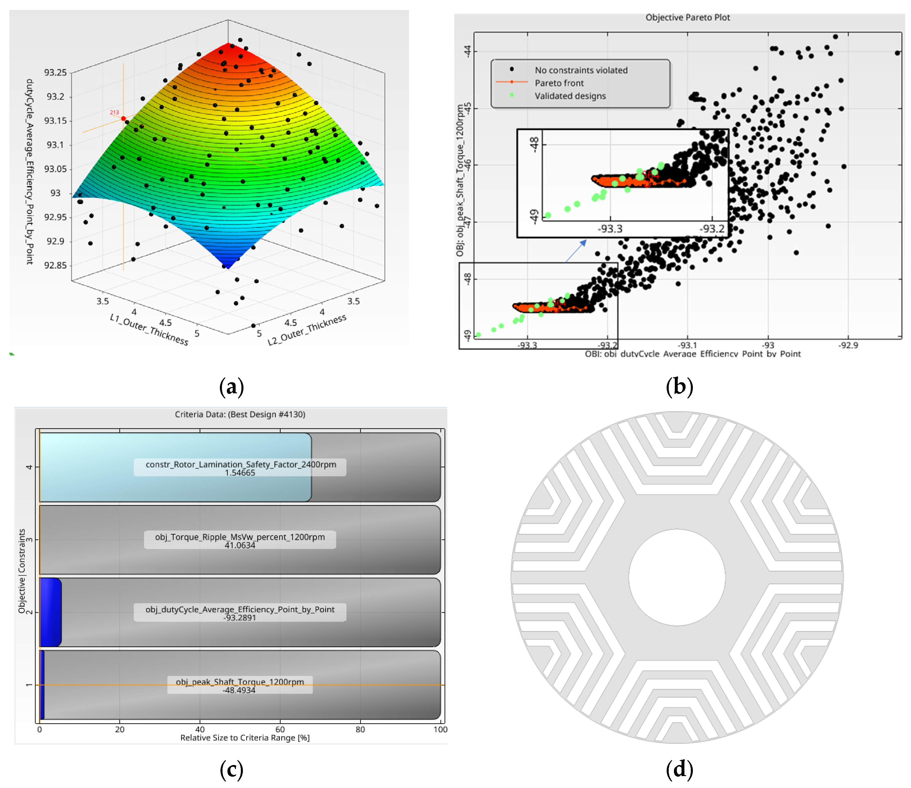
- Automatic selection: It automatically chooses the best-fitting model type based on prediction quality. The algorithm used is called the Adaptive Metamodel of Optimal Prognosis (AMOP).
- Accuracy evaluation: It uses metrics like the Coefficient of Prognosis (CoP) to assess model reliability.
- Multi-objective support: It is capable of modeling multiple objectives simultaneously.
- Efficient computation: It reduces simulation time by replacing costly simulations with fast surrogate models.
3.1. Steady-State Optimization Analysis
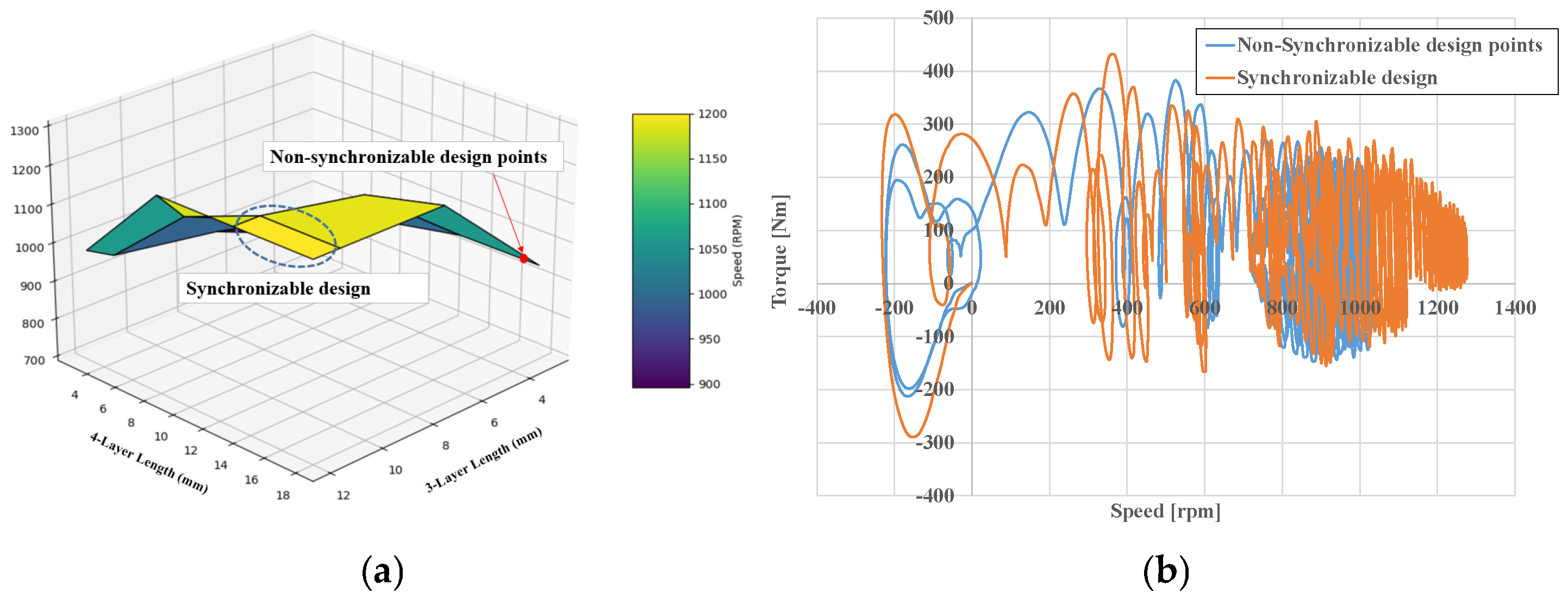
3.2. Startup Optimization Analysis
- Optimization Design Step II.
- Objective function: Maximize the torque (Tmax)/check whether it is synchronized.
- Constraint: Maximum torque > 45.1 N·m.
- Design variables: 0 mm ≤ Y1 ≤ 18 mm, 0 mm ≤ Y2 ≤ 12 mm, 0 mm ≤ Y3 ≤ 6 mm.
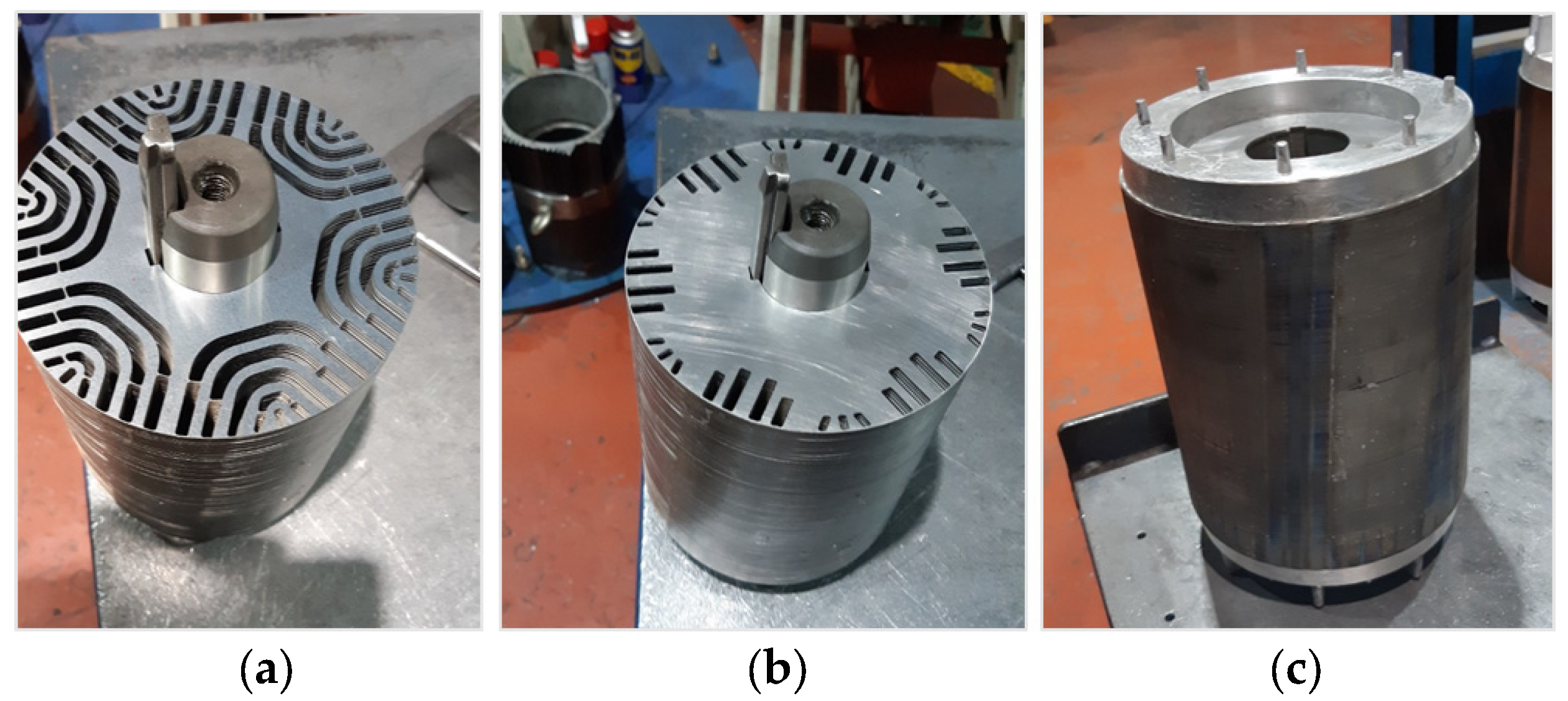
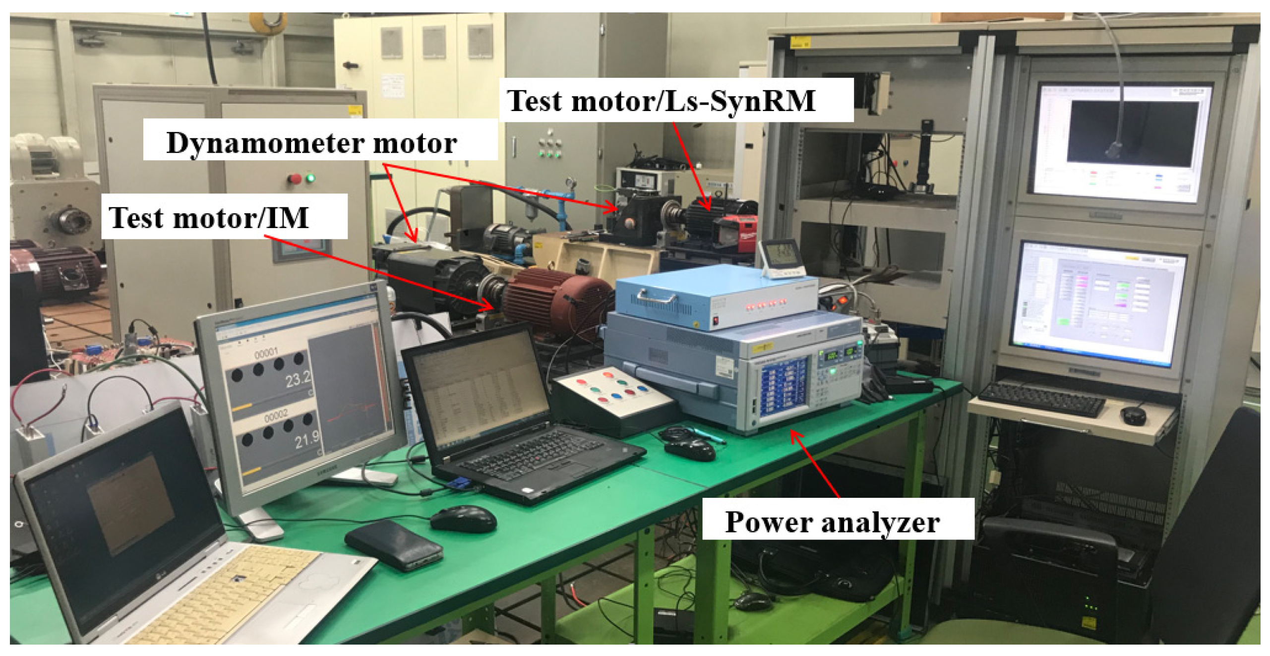
4. Prototype Manufacturing and Experiments
5. Conclusions
Funding
Data Availability Statement
Conflicts of Interest
Appendix A

| Motor Type | Key Cost Components | Rare Earth Materials | Rotor Complexity | Relative Manufacturing Cost |
|---|---|---|---|---|
| IM | Al/Cu rotor, standard stator | None | Low (die-cast aluminum) | 100% (baseline) |
| SynRM | No magnets, flux barrier rotor | None | Moderate (laminated punching) | ~90–100% |
| LS-SynRM | Squirrel cage + flux barriers | None | High (dual rotor structure) | ~95–110% |
| PMSM | IPM/SPM + embedded magnets | Yes (NdFeB) | High (magnet insertion) | ~130–160% |
| Method | Analysis Step | Time Per Design | Number of Designs | Total Time |
|---|---|---|---|---|
| Traditional FEA-based Approach | Steady-state FEA | 5 min | 6000 | 500 h |
| Mechanical stress FEA | 3 min | 6000 | 300 h | |
| Transient FEA | 1 h 40 min | 125 | 208.3 h | |
| Iterative mechanical check loops | >2 iterations | - | +>300 h | |
| Total (est.) | >1300 h | |||
| Proposed Approach | High-fidelity FEA for metamodel | 8 min | 500 | 66.7 h |
| Metamodel-based optimization | <1 s | 6000 | 12 min | |
| Transient FEA | 1 h 40 min | 125 | 208.3 h | |
| Total (est.) | 275 h |
References
- Kersten, A.; Liu, Y.; Pehrman, D.; Thiringer, T. Rotor Design of Line-Start Synchronous Reluctance Machine with Round Bars. IEEE Ind. Appl. 2019, 55, 3685–3696. [Google Scholar] [CrossRef]
- Ni, R.; Xu, D.; Wang, G.; Gui, X.; Zhang, G.; Zhan, H.; Li, C. Efficiency enhancement of general AC drive system by remanufacturing induction motor with interior permanent-magnet rotor. IEEE Trans. Ind. Electron. 2016, 63, 808–819. [Google Scholar] [CrossRef]
- de Almeida, A.T.; Ferreira, F.J.T.E.; Baoming, G. Beyond induction motors—Technology trends to move up efficiency. IEEE Trans. Ind. Appl. 2014, 50, 2103–2114. [Google Scholar] [CrossRef]
- Ferreira, F.J.T.E.; Leprettre, B.; de Almeida, A.T. Comparison of protection requirements in IE2- IE3- and IE4-class motors. IEEE Trans. Ind. Appl. 2016, 52, 3603–3610. [Google Scholar] [CrossRef]
- Chasiotis, I.D.; Karnavas, Y.L. A Computer Aided Educational Tool for Design, Modeling, and Performance Analysis of Brushless DC Motor in Post Graduate Degree Courses. Comput. Appl. Eng. Educ. 2018, 26, 749–767. [Google Scholar] [CrossRef]
- Tabassum, A.A.; Cho, H.M.; Mahmud, M.I. Essential Features and Torque Minimization Techniques for Brushless Direct Current Motor Controllers in Electric Vehicles. Energies 2024, 17, 4562. [Google Scholar] [CrossRef]
- Frias, A.; Kedous-Lebouc, A.; Chillet, C.; Albert, L.; Calegari, L.; Messal, O. Loss Minimization of an Electrical Vehicle Machine Considering Its Control and Iron Losses. IEEE Trans. Magn. 2016, 52, 8102904. [Google Scholar] [CrossRef]
- Costin, M.; Lazar, C. Field-Oriented Predictive Control Structure for Synchronous Reluctance Motors. Machines 2023, 11, 682. [Google Scholar] [CrossRef]
- Tawfiq, K.B.; Ibrahim, M.N.; Sergeant, P. Power Loss Analysis of a Five-Phase Drive System Using a Synchronous Reluctance Motor and an Indirect Matrix Converter with Reduced Switching Losses. Machines 2022, 10, 738. [Google Scholar] [CrossRef]
- Walch, D.; Blechinger, C.; Schellenberger, M.; Hofmann, M.; Eckardt, B.; Lorentz, V.R.H. Detection of Demagnetization Faults in Electric Motors by Analyzing Inverter Based Current Data Using Machine Learning Techniques. Machines 2024, 12, 468. [Google Scholar] [CrossRef]
- Du, Y.; Dong, Z.; Zhan, H.; Wu, L.; Zhou, K.; Yu, L.; Fang, Y.; Sun, L. Investigation of Post-Demagnetization Torque Ripple in Fractional-Slot Surface-Mounted PM Wind Power Generators after Short Circuit Faults. IEEE Trans. Ind. Appl. 2024, 60, 215–228. [Google Scholar] [CrossRef]
- Onsal, M.; Cumhur, B.; Demir, Y.; Yolacan, E.; Aydin, M. Rotor Design Optimization of a New Flux-Assisted Consequent Pole Spoke-Type Permanent Magnet Torque Motor for Low-Speed Applications. IEEE Trans. Magn. 2018, 54, 8206005. [Google Scholar] [CrossRef]
- Tawfiq, K.B.; Ibrahim, M.N.; EL-Kholy, E.E.; Sergeant, P. Performance Improvement of Synchronous Reluctance Machines—A Review Research. IEEE Trans. Magn. 2021, 57, 10. [Google Scholar] [CrossRef]
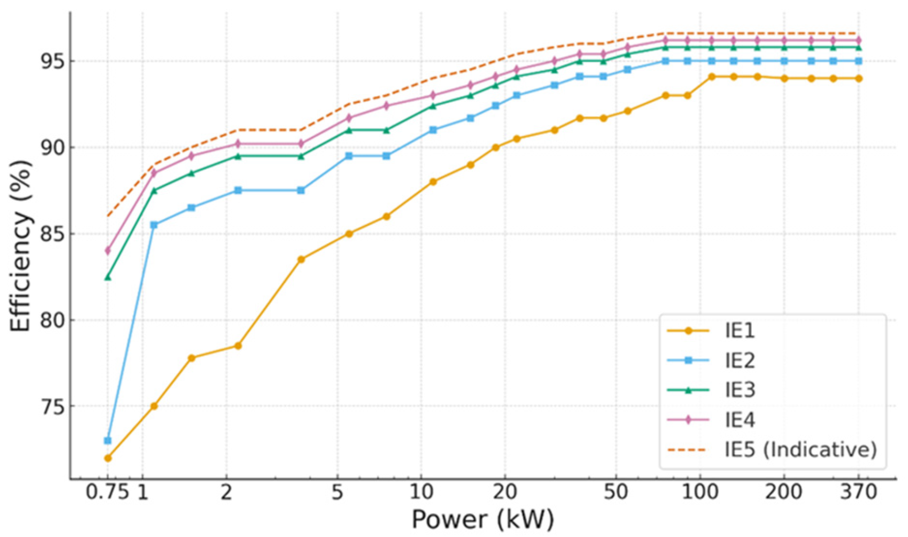
- IEC 60034-30-1; Rotating Electrical Machines—Part 30-1: Efficiency Classes of Line Operated AC Motors. International Electrotechnical Commission: Geneva, Switzerland, 2025.
- Chen, S.-G.; Lin, F.-J.; Huang, M.-S.; Yeh, S.-P.; Sun, T.-S. Proximate maximum efficiency control for synchronous reluctance motor via AMRCT and MTPA control. IEEE/ASME Trans. Mechatron. 2023, 28, 1404–1414. [Google Scholar] [CrossRef]
- Chen, S.-G.; Lin, F.-J.; Liang, C.-H.; Liao, C.-H. Intelligent maximum power factor searching control using recurrent chebyshev fuzzy neural network current angle controller for SynRM drive system. IEEE Trans. Power Electron. 2021, 36, 3496–3511. [Google Scholar] [CrossRef]
- Ban, B.; Stipetic, S. Systematic Metamodel-Based Optimization Study of Synchronous Reluctance Machine Rotor Barrier Topologies. Machines 2022, 10, 712. [Google Scholar] [CrossRef]
- Lopez-Torres, C.; Espinosa, A.G.; Riba, J.-R.; Romeral, L. Design and optimization for vehicle driving cycle of rare-earth-free SynRM based on coupled lumped thermal and magnetic networks. IEEE Trans. Veh. Technol. 2017, 67, 196–205. [Google Scholar] [CrossRef]
- Orlova, S.; Auzins, J.; Pugachov, V.; Rassõlkin, A.; Vaimann, T. Response Surface Method for Optimization of Synchronous Reluctance Motor Rotor. Machines 2022, 10, 897. [Google Scholar] [CrossRef]
- Liu, H.-C.; Kim, I.-G.; Oh, Y.J.; Lee, J.; Go, S.-C. Design of permanent magnet-assisted synchronous reluctance motor for maximized Back-EMF and torque ripple reduction. IEEE Trans. Magn. 2017, 53, 8202604. [Google Scholar] [CrossRef]
- Villani, M.; Fabri, G.; Credo, A.; Leonardo, L.; Collazzo, F. Line-Start Synchronous Reluctance Motor: A Reduced Manufacturing Cost Avenue to Achieve IE4 Efficiency Class. IEEE Access 2022, 10, 100094–100103. [Google Scholar] [CrossRef]
- Jeon, K.-W.; Chung, T.-K.; Hahn, S.-C. NEMA Class A Slot Shape Optimization of Induction Motor for Electric Vehicle Using Response Surface Method. In Proceedings of the 2011 International Conference on Electrical Machines and Systems, Beijing, China, 20–23 August 2011. [Google Scholar]
- Lee, G.; Min, S.; Hong, J.-P. Optimal Shape Design of Rotor Slot in Squirrel-Cage Induction Motor Considering Torque Characteristic. IEEE Trans. Magn. 2013, 49, 2197–2200. [Google Scholar] [CrossRef]
- Kamper, M.J.; Van Der Merwe, F.S.; Williamson, S. Direct Finite Element Design Optimisation of the Cageless Reluctance Synchronous Machine. IEEE Trans. Energy Convers. 1996, 11, 547–553. [Google Scholar] [CrossRef]
- Gundogdu, T.; Komurgoz, G. A systematic design optimization approach for interior permanent magnet machines equipped with novel semi-overlapping windings. Struct. Multidiscip. Optim. 2021, 63, 1491–1512. [Google Scholar] [CrossRef]
- Lampinen, J. Multi-Constrained Nonlinear Optimization by the Differential Evolution Algorithm. In Soft Computing and Industry; Springer: London, UK, 2002. [Google Scholar]
- Lee, J.; Seo, J.H.; Kikuchi, N. Topology optimization of switched reluctance motors for the desired torque profile. Struct. Multidiscip. Optim. 2010, 42, 783–796. [Google Scholar] [CrossRef]
- Lee, C.; Jang, I.G. Topology optimization of multiple-barrier synchronous reluctance motors with initial random hollow circles. Struct. Multidiscip. Optim. 2021, 64, 2213–2224. [Google Scholar] [CrossRef]
- IEC 60034-2-1; Rotating Electrical Machines—Part 2-1: Standard Methods for Determining Losses and Efficiency from Tests (Excluding Machines for Traction Vehicles). International Electrotechnical Commission (IEC): Geneva, Switzerland, 2014.
- Gurutz, A.; Caballero, D.; Prieto, B.; Martinez-Iturralde, M.; Elosegui, I. Eliminating rare earth permanent magnets on low-speed high-torque machines: A performance and cost comparison of synchronous reluctance machines, ferrite permanent magnet-synchronous reluctance machines and permanent magnet synchronous machines for a direct-drive elevator system. IET Electr. Power Appl. 2021, 15, 370–378. [Google Scholar]
- Kazakbaev, V.; Parkht, V.; Dmitrievskii, V.; Oshurbekov, S.; Golovanov, D. Life Cycle Energy Cost Assessment for Pump Units with Various Types of Line-Start Operating Motors Including Cable Losses. Energies 2020, 13, 3546. [Google Scholar] [CrossRef]
- Ozcelik, N.G.; Dogru, U.E.; Imeryuz, M.; Ergene, L.T. Synchronous Reluctance Motor vs. Induction Motor at Low-Power Industrial Applications: Design and Comparison. Energies 2019, 12, 2190. [Google Scholar] [CrossRef]


| Item | Unit | Value | 8/12 Stator, Slot of Stator |
|---|---|---|---|
| Size (Outer Diameter) Stator/Rotor | mm | 220, 144 |  |
| Stack Length | mm | 170 | |
| Pole/Slot Number | 6/54 | ||
| Air Gap | mm | 0.5 | |
| Rotor Conductor Number | - | 42 | |
| Coil Size (Bare) | mm | 0.85 | |
| No. of Turns, Strands | - | 17, 6 | |
| Phase Resistance@20 degC | Ω | 0.52 | |
| Fill Factor | % | 43 | |
| Insulation Paper Thickness | mm | 0.22 |
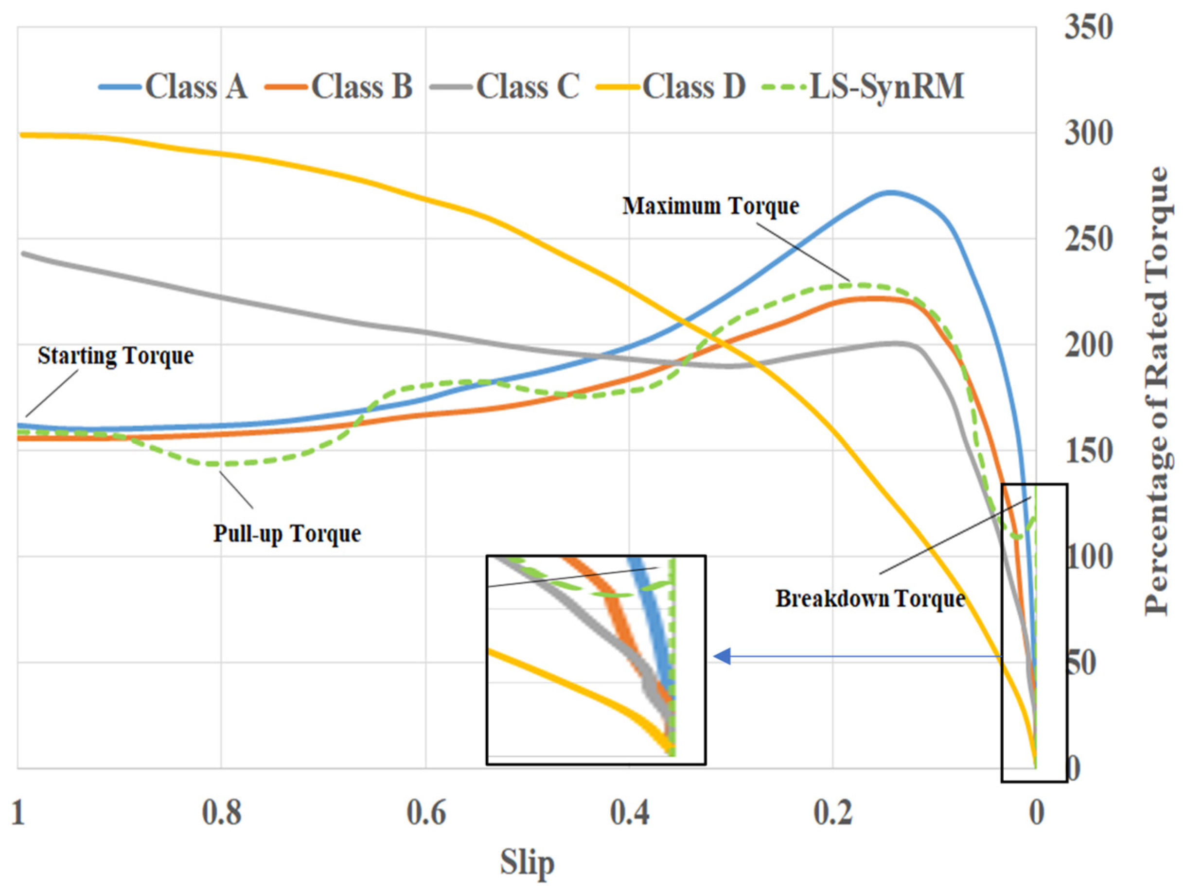
| NEMA Class A | NEMA Class B | NEMA Class C | NEMA Class D | |
|---|---|---|---|---|
| Shape |  |  |  |  |
| Full-load slip | Low 5% | 5% | 5% | 5~13% |
| Starting current/ Locked rotor current | High > 650% | Normal ≈ 650% | Normal ≈ 650% | Normal ≈ 650% |
| Locked rotor torque | Normal 90~100% | Normal 80~100% | High > 150% | Very high > 200% |
| Breakdown torque | Normal > 200% | Normal ≈ 200% | Normal ≈ 200% | Normal > 200% |
| Shape description | The cross-section is large (low resistance) and not too deep (low reactance). | It is similar to design A, except the deeper bar results in a lower irush and slightly lower torques. | The high resistance of the upper cage delivers a high start torque. | The bar shape and materials (brass or a similar alloy) are used for a high resistance (high starting torque) and high slip. |
| Application | Machines, tools, fans | General industrial applications | Conveyors | Hoists |
| Item (Constant Parameter) | Unit | Symbol | Value |
|---|---|---|---|
| Stator/rotor/shaft diameter | mm | Dso/Dro/Dri | 220/144/50 |
| Stack length | mm | Lstk | 170 |
| No. of phase/paths/tuns/strands | - | Nph/ap/Nc/NS | 3/1/17/6 |
| No. of poles/slots/barrier layers | - | p/Ns/Nb | 6/54/4 |
| Air gap | mm | δ | 0.5 |
| Item (Optimization Variables) | Unit | Symbol | Value/Range |
| Width of barrier layer 1~4 | mm | W1b/W2b/W3b/W4b | [2/4] |
| Width of segment layer 1~4 | mm | W1s/W2s/W3s/W4s | [3/5.5] |
| Width of rib layer 1~4 | mm | W1s/W2s/W3s/W4s | [0.5/0.8] |
| Item (Optimization Goals) | Unit | Symbol | Criterion |
| Stress safety factor at 2*baserpm | - | SF | Maximize/>1.5 |
| Maximum torque | Nm | Tmax | Maximize |
| Efficiency | % | Eff | Maximize |
| Pictutre | Item | Unit | Value |
|---|---|---|---|
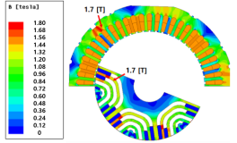 flux density distribution at 5.5 kW, 1200 rpm | Power at 1200 rpm | kW | 5.5 |
| Line voltage | Vrms | 380 | |
| Efficiency | % | 92.6 | |
| Power factor | 0.73 | ||
| Current | Arms | 12.3 | |
| Iron loss | W | 96.1 | |
| Copper loss | W | 239.2 | |
| Rotor copper loss | W | 33.1 | |
| Additional loss | W | 68.0 |
| Item | Unit | Value | ||
|---|---|---|---|---|
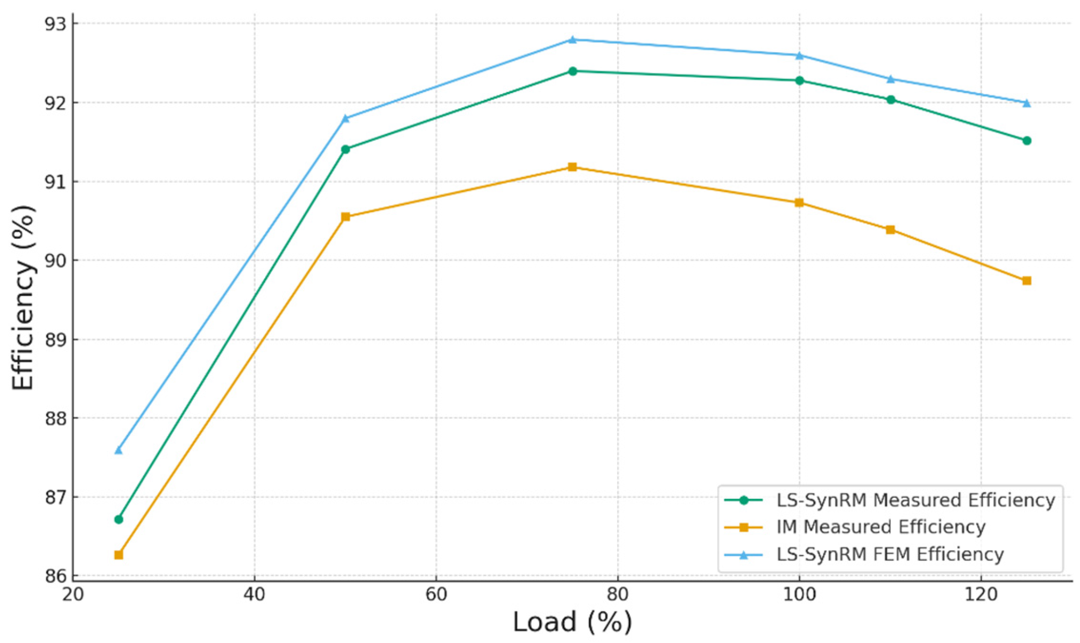
| LS-SynRM/FEM | IM/Test | LS-SynRM/Test | ||
| Power | kW | 5.5@1200 rpm | 5.5@1175 rpm | 5.5@1200 rpm |
| Efficiency | % | 92.6 | 90.7 | 92.2 |
| Power factor | 0.73 | 0.754 | 0.685 | |
| Current | Arms | 12.3 | 12.28 | 13.16 |
| Iron loss | W | 96.1 | 106 | 103.6 |
| Copper loss | W | 239.2 | 249.5 | 268.2 |
| Rotor copper loss | W | 33.1 * | 124.6 | 1.0 |
| Additional loss | W | 68 | 84.7 | 91.1 |
Disclaimer/Publisher’s Note: The statements, opinions and data contained in all publications are solely those of the individual author(s) and contributor(s) and not of MDPI and/or the editor(s). MDPI and/or the editor(s) disclaim responsibility for any injury to people or property resulting from any ideas, methods, instructions or products referred to in the content. |
© 2025 by the author. Licensee MDPI, Basel, Switzerland. This article is an open access article distributed under the terms and conditions of the Creative Commons Attribution (CC BY) license (https://creativecommons.org/licenses/by/4.0/).
Share and Cite
Liu, H.-c. Systematic Optimization Study of Line-Start Synchronous Reluctance Motor Rotor for IE4 Efficiency. Machines 2025, 13, 420. https://doi.org/10.3390/machines13050420
Liu H-c. Systematic Optimization Study of Line-Start Synchronous Reluctance Motor Rotor for IE4 Efficiency. Machines. 2025; 13(5):420. https://doi.org/10.3390/machines13050420
Chicago/Turabian StyleLiu, Huai-cong. 2025. "Systematic Optimization Study of Line-Start Synchronous Reluctance Motor Rotor for IE4 Efficiency" Machines 13, no. 5: 420. https://doi.org/10.3390/machines13050420
APA StyleLiu, H.-c. (2025). Systematic Optimization Study of Line-Start Synchronous Reluctance Motor Rotor for IE4 Efficiency. Machines, 13(5), 420. https://doi.org/10.3390/machines13050420