Article

Kinematics and Dynamics Analysis of a New 5-Degrees of Freedom Parallel Mechanism with Two Double-Driven Chains

1
College of Mechanical and Electrical Engineering, Hebei Normal University of Science & Technology, Qinhuangdao 066000, China
2
School of Vehicles and Energy, Yanshan University, Qinhuangdao 066004, China
3
Academy for Engineering and Technology, Fudan University, Shanghai 200433, China
4
Weichai Lovol Intelligent Agricultural Technology Co., Ltd., Weifang 261000, China
*
Author to whom correspondence should be addressed.
Machines 2025, 13(5), 419; https://doi.org/10.3390/machines13050419
Submission received: 16 April 2025 / Revised: 13 May 2025 / Accepted: 14 May 2025 / Published: 15 May 2025
(This article belongs to the Section Machine Design and Theory)

Abstract

:
This paper focuses on the design analysis of a novel 5-degrees of freedom (DOF) double-driven parallel mechanism (PM). By arranging two independent actuators on one branch chain, the mechanism can realize the five degrees of freedom of the moving platform only by relying on three branch chains, which have the characteristics of a compact structure and large workspace. Subsequently, the kinematic model of the mechanism is established, and the workspace, dexterity, and singularity characteristics are analyzed based on the derived model. Additionally, an explicit dynamic model of the mechanism is established based on the principle of virtual work. Finally, based on the dynamic model, the manipulability ellipsoid index and the inertial coupling strength index are proposed, and the distribution of these two kinds of dynamic performance indexes in the workspace is studied.

1. Introduction

Manufacturing is the cornerstone of modern industrial systems, with its development level directly impacting national industrial competitiveness. The pressing demand for precision and efficient machining of key components in high-end equipment manufacturing has become a critical bottleneck in industrial technological advancement. These components typically feature complex geometric characteristics such as large dimensions, intricate curved surfaces, and thick walls while constrained by stringent processing conditions and technical requirements that traditional manual and CNC can no longer adequately fulfill. Therefore, designing five-axis machining equipment with high performance, flexibility, and adaptability has inevitably become a trend in developing an advanced manufacturing industry [1,2,3,4].
Current machining robots are primarily categorized into three configurations: serial [5,6], hybrid [7,8], and parallel [9,10]. Serial robots excel in large curved surface component processing due to their extensive workspace and high flexibility [11]. Hybrid robots compensate for the low rigidity of serial architectures, offering new alternatives for aluminum alloy component machining [12]. Parallel 5-DOF robots (e.g., Metrom [13] and DiaRom [14,15]) demonstrate unique advantages in aerospace precision machining owing to their high stiffness, accuracy, and coupled motion characteristics. Although existing parallel robots have exhibited distinct advantages in large-scale component machining and achieved success in respective applications, the more significant number of branch chains and joints leads to more structural constraints, and these factors lead to small workspace and rotation capacity [16]. Therefore, the research and development of novel five-DOF parallel mechanisms represent a crucial technological pathway and potential breakthrough for advancing high-performance machining equipment [17].
In conventional parallel mechanisms, each actuated branch chain connecting the moving platform to the fixed base is typically equipped with a single active joint. This design paradigm establishes a direct correlation between the number of DOF and the number of actuated branch chains, such that the mechanism’s mobility is precisely determined by its number of independently driven chains [18]. Consequently, five actuated branch chains must achieve independent motion with five DOF. However, as the number of branch chains increases, the mechanism’s topology becomes more complex, significantly elevating design and manufacturing costs and exacerbating issues related to interference and dynamic coupling among the branches [19]. To solve the above problems, some scholars have combined the parallel mechanism with the series mechanism to form a hybrid mechanism with complementary advantages, which not only effectively expands the operating space of the mechanism but also overcomes the shortcomings of the traditional series mechanism, such as insufficient stiffness and error accumulation to a certain extent [20,21]. However, stiffness and positioning accuracy of the end effector of the hybrid mechanism are still affected by the serial structure, so it is difficult to achieve the high precision characteristic of the pure parallel mechanism [22].
In order to address both the requirements for DOF and overall mechanism performance, the double-driven PM, as a novel PM, has gradually attracted increasing attention in the academic community [23,24,25]. Integrating multiple actuators within a single branch chain can significantly reduce the number of branch chains while still satisfying the desired DOF, simplifying the overall structure and minimizing the potential for interference. As a member of the parallel topology family, the dual-drive PM retains the advantages of compact design, high stiffness, and excellent positioning accuracy, demonstrating strong potential for future development. Lu et al. [26] proposed a compound rotational/linear UPS and used it to design a three branch chain, 2UPS-SPR dual-drive PM with 5-DOF and analyzed its kinematics and statics. Zhao et al. [27] proposed and studied a 6-(PRRR)US dual-drive PM based on a planar five-bar mechanism, demonstrating its strong capabilities in attitude adjustment and vibration isolation through kinematic and dynamic analysis. Wang et al. [22] designed a 5-DOF double-driven PM (PUU-2PRRS) and analyzed its workspace, dexterity, volume, and dimensional optimization. Niu et al. [28] proposed a dual-driven PM (2PRPS/PSR) and optimized motion performance based on transmissibility, workspace/volume ratio, and mass. Rong et al. [29] proposed a dual-driven 5-DOF parallel mechanism 2PRPU/PRPS with only three limbs and 17 joints based on Lie group theory, the simplest structural form of 5-DOF PMs. Nevertheless, research in this area is still in its early stages, with limited studies on structural design and practical engineering applications. Further support through systematic theoretical modeling and prototype validation is urgently needed to advance this promising field.
As can be seen from the above, research on 5-DOF PM with two double-driven branch chains is still in its early stages, and such mechanisms exhibit promising application prospects. This paper proposes a novel P(2PRPU)/PRPS PM with two double-driven branch chains based on the dual-drive concept. Innovatively, the mechanism consists of only three double-driven branches, which significantly reduces branch interference. Moreover, some of the actuators are fixed on the base, thereby reducing the mass of the moving parts, improving dynamic response speed, and minimizing the impact of inertial loads on the structure. Compared with the current 5-DOF PMs, the mechanism proposed in this paper not only has only 3 branch chain, 17 single-DOF motion pairs as a whole, with a simpler structure, but also reduces the motion mass by fixing some drive pairs, enabling it to have a good dynamic response.
The structure of this paper is as follows. In Section 2, the structure of the proposed PM is introduced, and its kinematic performance is analyzed through the derivation of a 5 × 5 Jacobian matrix. In Section 3, the dynamic model of the proposed mechanism is established, along with an analysis of its dynamic manipulability ellipsoid and the inertia coupling strength of the branch chains. Conclusions are drawn in Section 4.

2. Structural and Kinematic Analysis

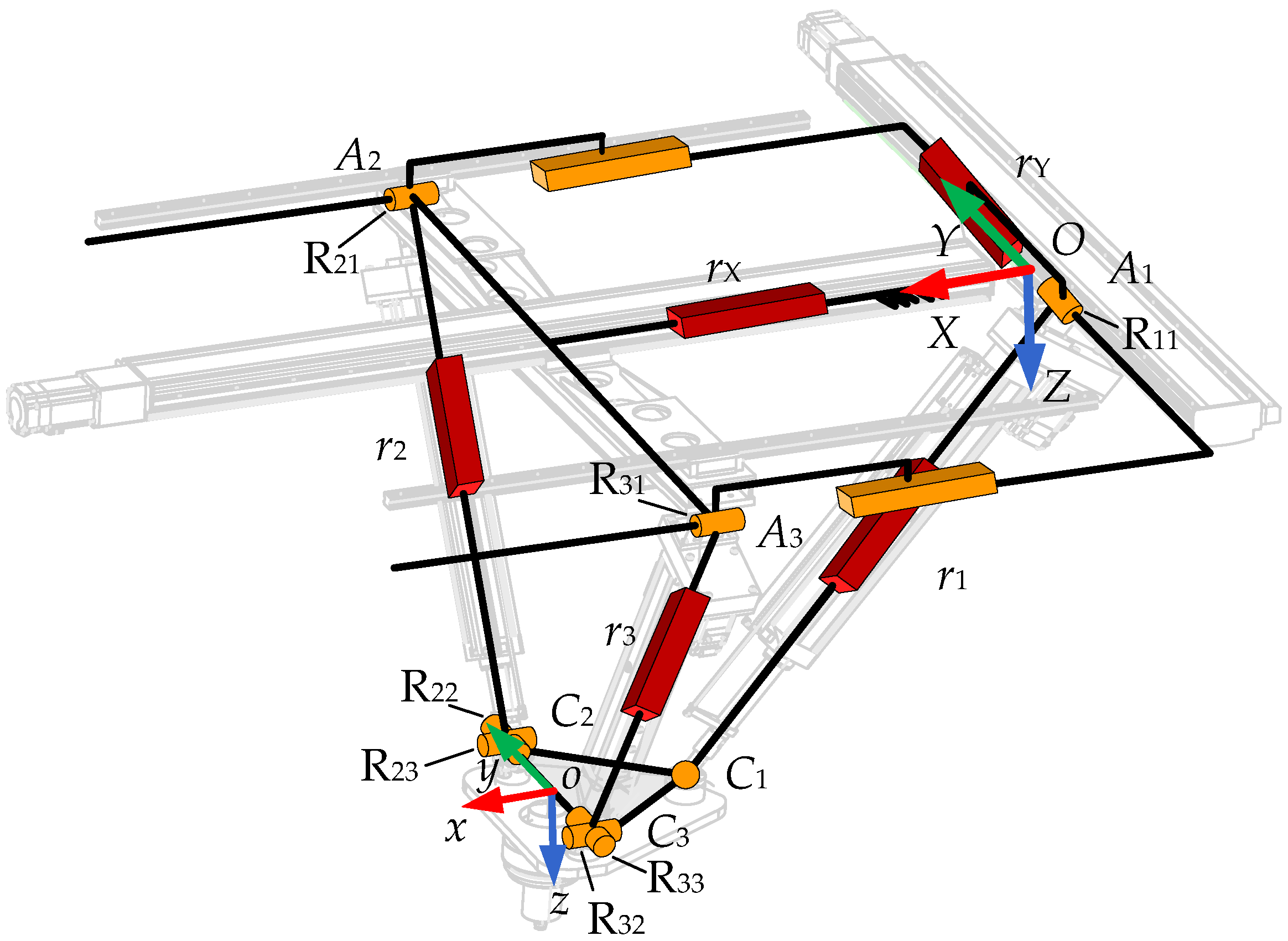
2.1. Configuration Description and Mobility Analysis

Figure 1 shows the new 5-DOF PM with two double-driven chains. It consists of a base and a moving platform, which are connected by branch chain r1, branch chain r2, branch chain r3, linear modules, and guide rails. Branch chain 1 comprises three key components: a revolute joint, an electric push rod (i.e., prismatic joint), and a sphere joint, which, together with the linear module rY constitute a PRPS-type branch chain. Branch chains 2 and 3 comprise three key components: a revolute joint, an electric push rod, and a universal joint, which, together with the passive guide rails, constitute a PRPU-type branch chain.
The linear modules rX and rY are rigidly mounted on the base among the five driving components. Linear modules rX propels the branch chains 2 and 3 for anteroposterior motion, while linear modules rY drive branch chain 1 for lateral movement, constituting a parallel mechanism with two double-driven chains. This innovative configuration achieves two significant advancements compared to traditional 5-DoF PMs: it reduces the number of required branch chains to only three, significantly minimizing inter-branch interference, and it incorporates more actuators arranged on the base, which helps reduce vibration and improve precision. The PM proposed in references [30,31] also adopts the design of fixing the drive motor on the frame or the static platform. As a result, this parallel mechanism has potential applications in machine tools, walking robots, industrial robotic arms, naval cargo handling systems, and satellite monitoring platforms.
For convenience of description, let point A1 denote the rotation center of the revolute joint in the RPS branch chain, and let point C1 represent the rotation center of the spherical joint. For branch chains 2 and 3, the rotation centers of their revolute joints are defined as A2 and A3, respectively, whereas the rotation centers of their universal joints are designated as C2 and C3. The fixed coordinate frame O-XYZ (denoted as {B}) is established with the midpoint O of branch chain Y as the origin; here, the X-axis aligns with branch chain X, the Y-axis with branch chain Y, and the Z-axis is determined by the right-hand rule. The moving coordinate frame o-xyz (denoted as {m}) is defined with the midpoint o of C1C2 as the origin: the y-axis coincides with C1C2, the z-axis is perpendicular to the plane formed by points C1, C2, and C3, and the x-axis is oriented according to the right-hand rule. Moreover, points A2, A3, C2, C3, and o are coplanar, with the normal vector of this plane parallel to the X-axis.
Let ǁ be a parallel constraint, | be a collinear constraint, and ⊥ be a perpendicular constraint, respectively. Let Rij (i = 1, 2, 3; j = 1, 2) be the j-th R joint in the i-th branch chain ri. Some geometrical constraints are satisfied for the P(2PRPU)/PRPS PM as follows (see Figure 1):
r Y | Y , R 11 | Y , r 1 Y , r X | X , A 2 A 3 Y r i R i 1 , R i 1 R i 2 , R i 2 R i 3 , R i 3 | y i = 2 , 3
Since the P(2PRPU) branch chain is equivalent to a 2PRPU branch chain, the P(2PRPU)/PRPS PM can be regarded as a 2PRPU/PRPS PM, the twist system of the two PRPU branch chains can be expressed as:
$ i 1 = 0 0 0 ; 1 0 0 $ i 2 = 1 0 0 ; 0 0 0 $ i 3 = 0 0 0 ; 0 m i 3 n i 3 $ i 4 = 1 0 0 ; 0 q i 4 r i 4 $ i 5 = 0 m i 5 n i 5 ; p i 5 q i 5 r i 5
Adopting the reciprocal screw theory, the branch chain wrench system can be expressed as:
$ i r = 0 0 0 ; 0 n i 5 m i 5
where S i r represents the constrained torque perpendicular to Ri2 and Ri3, based on the constraint relationship in Equation (3), it is deduced that Ri2 is parallel to the X-axis, while R23 and R33 are collinear with the y-axis. Consequently, the U-joint planes in the two PRPU branch chains are mutually parallel, and the constrained torque of the two branch chains is likewise parallel, forming a common constraint. As a result, the 2PRPU/PRPS is constrained solely by a constrained torque along the z-axis. Moreover, since the constraint relationships remain invariant during motion, the expression of the wrench system is constant, and the 2PRPU/PRPS or P(2PRPU)/PRPS PM always remain 2-rotational and 3-translational (2R3T) five DOF.

2.2. Jacobian Matrix Analysis

Let the rotational transformation matrix BRm from the reference frame {B} to {m}, Ai and Ci represent the vector of Ai and Ci in {B}, Ai and Ci can be written as:
A 1 = 0 e 1 s α s β + y 0 , A 2 = x 0.5 L 0 , A 3 = x 0.5 L 0 , o = x y z C 1 = R m B h 0 0 + o , C 2 = R m B 0 0.5 e 0 + o , C 3 = R m B 0 0.5 e 0 + o R m B = c β 0 s β s α s β c α s α c β c α s β s α c α c β
where L is the distance from A2 to A3, e denotes the distance from C2 to C3, h denotes the distance from o to C1, α and β are Euler angles, ci and si denote cos(θi) and sin(θi), o is the position vector of point o.
From Equation (4), li can be derived by the following:
l i = C i A i l 1 = e 1 c β + x 2 + e 1 c α s β + z 2 , l 2 = e 2 c α + y L 2 + e 2 s α + z 2 l 3 = e 3 c α + y + L 2 + e 3 s α + z 2 , l x = x , l y = e 1 s α s β + y
Let δi, δX = [1 0 0]T, and δY = [0 1 0]T be the unit vector of branch chains ri (i = 1, 2, 3, X, Y). Based on Equation (5), the closed-loop constraint equation associated with each branch chain can be written as:
l Y δ Y + l 1 δ 1 e 1 = o l X δ X + l i δ i e i = o , i = 2 , 3
here ei is the vector of oCi. Let v, a be the velocity and acceleration vectors of o in {B}, ω and Ɛ be angular velocity and angular acceleration of {m} relative to {B}. By differentiating Equation (6) concerning time, it leads to:
v r Y δ Y + v r 1 δ 1 + ω 1 × l 1 δ 1 ω × e 1 = v v r X δ X + v r i δ i + ω i × l i δ i ω × e i = v , i = 2 , 3
where vri and ωi are actuated joint rate and angular velocity of branch ri. Dot multiply both sides of Equation (7) by δi, δX, and δY, respectively. It leads to:
v r X v r Y v r i = J m v ω , J m = J X J Y J i = δ X T e 2 × δ X T δ Y T e 1 × δ Y T δ i T e i × δ i T
For the P(2PRPU)/PRPS PM in this paper, the relationship between V = [v ω]T and the independent kinematic parameter q = [x, y, z, α, β]T can be expressed as:
v ω = J B x ˙ y ˙ z ˙ α ˙ β ˙ , J B = E 3   0 3 × 2 0 3 × 3 J ω , J ω = 1 0 0 c α 0 s α
Substitute Equation (9) into Equation (8) and the relationship between the input and output parameters can be expressed as follows:
V q = J D 1 V r , J D = J m J B V q = x ˙ y ˙ z ˙ α ˙ β ˙ T V r = v r X v r Y v r 1 v r 2 v r 3 T
where J D 1 is the Jacobian matrix of P(2PRPU)/PRPS PM.

2.3. Kinematic Performance Analysis and Optimization

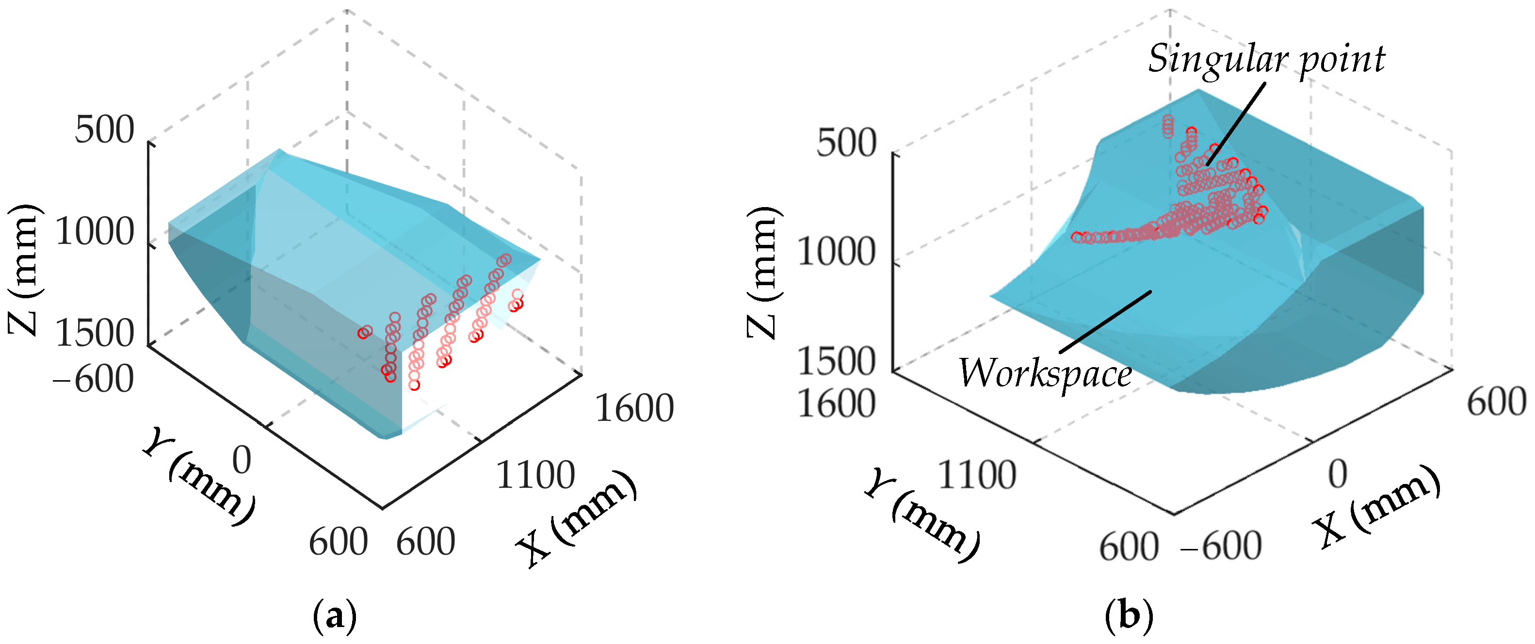
2.3.1. Singularity Analysis

Singularity analysis is a fundamental issue of kinematic analysis and performance evaluation. The kinematic performance of the PM deteriorates in singular configurations. In this study, singularities are investigated through the analysis of the velocity performance of the mechanism. With an input velocity fixed at 10 mm/s, the output velocity at the center of the moving platform is expected to remain relatively moderate under normal operating conditions. However, if the output velocity at a given position exceeds 1000 mm/s, this paper considers that the transmission characteristics have changed, which means that the mechanism has encountered a singularity and can no longer work properly.
Figure 2 shows the distribution of singular points within the workspace of the P(2PRPU)/PRPS PM at different orientation angles, where L = 1200 mm, e = 300 mm, h = 240 mm, 990 mm ≤ li ≤ 1490, 600 mm ≤ lX ≤ 1600 mm, −700 mm ≤ lY ≤ 700. As shown in Figure 2, these singular points can not only form a continuous surface but also demonstrate that the workspace of the mechanism and the distribution of its singular points are highly dependent on changes in the orientation angle. This phenomenon indicates that when the P(2PRPU)/PRPS PM performs operational tasks, it is essential to thoroughly consider the characteristics of singularity surfaces under varying orientations and adjust the control strategy accordingly to ensure stable operation across all poses.

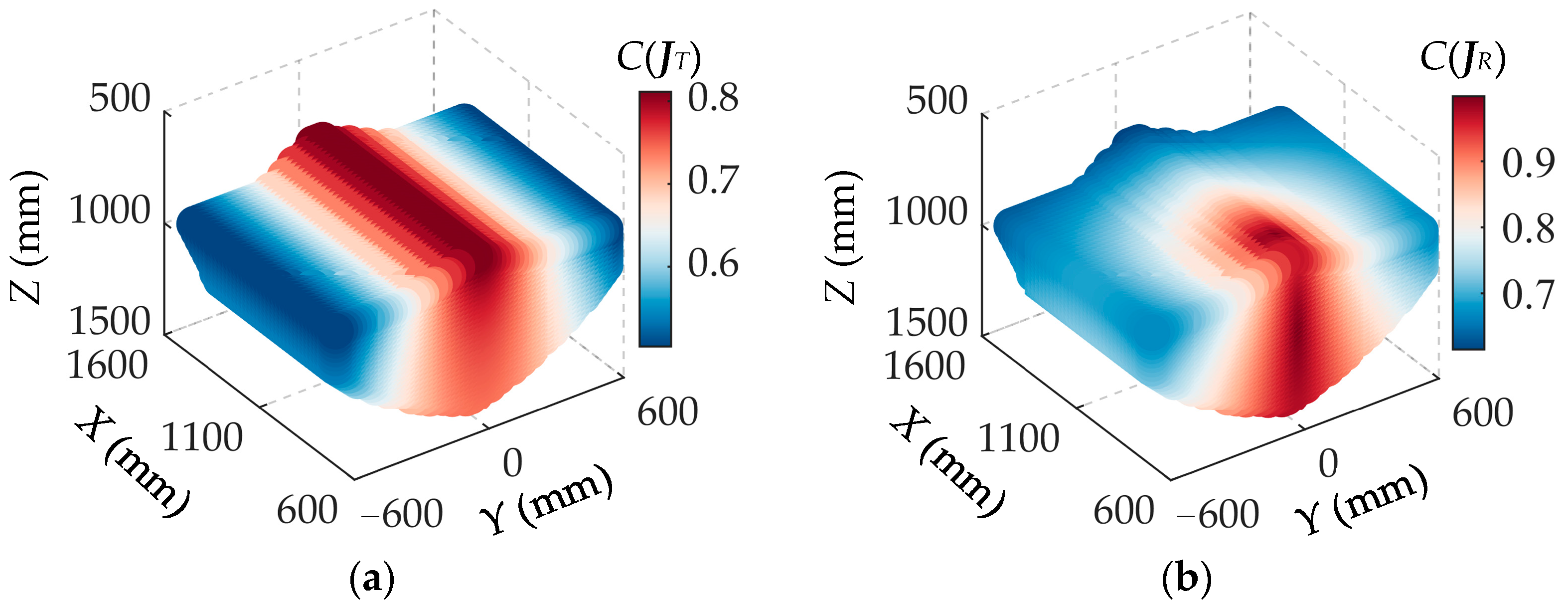
2.3.2. Dexterity Analysis

Dexterity is an important performance index that directly reflects the kinematic performance of the PM. Local condition indicators should be used to analyze a mechanism with both translational and rotational DOF. Equation (10) can be rewritten as:
x ˙ y ˙ z ˙ = J T V r , α ˙ β ˙ = J R V r
where JT is a 3 × 5 form matrix formed by taking the first three rows of J D 1 , JR is a 2 × 5 form matrix formed by taking the last two rows of J D 1 . JT and JR are the local matrices related to the Jacobian matrix. Based on this, the local dexterity index (LDI) of the position and orientation parts of the Jacobian matrix can be obtained, denoted as C(JT) and C(JR), as follows:
C J T = 1 k J T , C J R = 1 k J R
where k(JT) and k(JR) are the condition numbers of the Jacobian matrixes JT and JR, respectively. k(JT) and k(JR) are calculated as follows:
k J T = J T J T + 1 , k J R = J R J R + 1
The local dexterity index ranges from 0 to 1. The local dexterity index is 1, and the mechanism has the highest sensitivity and is isotropic. Conversely, the mechanism enters a singular configuration as the local dexterity index tends to 0. When the posture is fixed to take α = β = 0, the local dexterity index for the mechanism is shown in Figure 3.
As shown in Figure 3, the translational velocity dexterity index C(JT) exhibits symmetry about the Y = 0 plane, peaking near the Y = 0 plane and progressively decreasing with increasing Y coordinates, ultimately reaching its minimum at the extremities of the workspace along the Y-axis. Similarly, the angular velocity dexterity index C(JR) demonstrates symmetry about the Y = 0 plane, with its high-performance zones predominantly concentrated in the central workspace region near the origin.

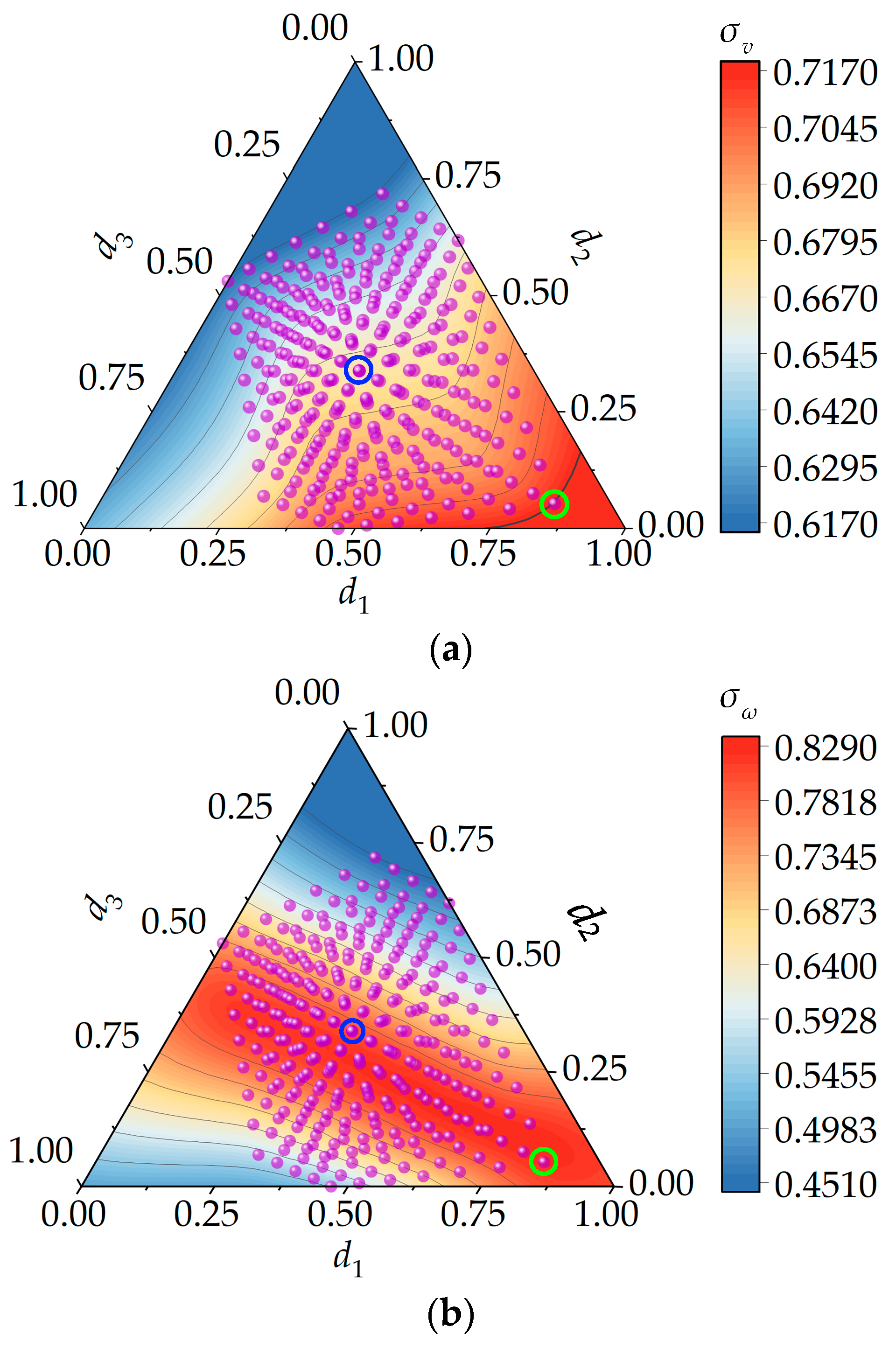
2.3.3. Optimization of Design Parameters

The kinematic performance of PMs exhibits significant dependence on their dimensional parameters. This study employs the global kinematic performance indexes σv and σω for parametric optimization, formulated as:
σ v = i = 1 N r ω C ( J T ) i N r ω , σ ω = i = 1 N r ω C ( J R ) i N r ω
where Nrw denotes the number of pose parameter points discretizing the workspace, with its physical interpretation corresponding to the workspace volume under the current dimensional parameters. Consequently, the geometrical meaning of indices σv and σω can be interpreted as the mean value of global kinematic performance indexes over the workspace.
The architectural parameters are as follows: L = 1100 mm: 50 mm: 1300 mm, e = 200 mm: 25 mm: 400 mm: 150 mm, h = 180 mm: 20 mm: 300 mm. Using the parameter design space (PDS), the design parameters are normalized as follows:
T = L + h + e d 1 = L T , d 2 = h T , d 3 = e T 0 < d 1 , d 2 , d 3 < 1 d 1 + d 2 + d 3 = 1
where T is a normalized factor, and di is a normalized nondimensional parameter. d1, d2, and d3 are assigned as the coordinate axes of a ternary plot. Each point within this plot corresponds to the values of the global kinematic indices under the current d design parameters of the mechanism.
The distributions of σv and σω can be obtained as shown in Figure 4, the σv is directly proportional to d1 and inversely proportional to d2, with the optimal region located in the lower right corner of the figure. The optimal region for σω exhibits a distinct band-like distribution.
Based on these observations, we can select the parameter combination that achieves the relatively optimal dexterity performance, corresponding to the coordinates marked by the green circle in Figure 4—the 253st scale combination: d1 = 0.7738, d2 = 0.1190, d3 = 0.1071, L = 1300 mm, e = 300 mm, h = 180 mm. This combination results in dexterity indices of σv = 0.7157 and σω = 0.8267. For comparison, the original configuration (blue circle) yields σv = 0.6707, σω = 0.8007.

3. Dynamic Analysis of the P(2PRPU)/PRPS PM

3.1. Velocity and Acceleration of Branch Chains

Taking the cross product with δi on both sides of Equation (7), we have:
δ 1 × v r Y δ Y + ω 1 l 1 δ 1 × ω × e 1 = δ 1 × v δ i × v r X δ X + ω i l i δ i ω i l i δ i δ i × ω × e i = δ i × v , i = 2 , 3
According to the principle of motion synthesis, the velocity vector of point Ci on the moving platform can be expressed as:
v i = v + ω × e i
Substituting Equation (16) into Equation (17), the angular velocity of ri(i = 1, 2, 3) can be derived as:
ω i = J ω i V J ω 1 = 1 l 1 δ ^ 1 δ ^ 1 e ^ 1 δ Y J Y J ω i = 1 l i δ ^ i δ ^ i e ^ i δ X J X , i = 2 , 3
Here êi represents the skew-symmetric matrix of the ei. Taking the time derivative of Equation (9), we can obtain angular acceleration and acceleration of the moving platform, respectively:
a = J v A q + V q T H v V q , H v = h v 1 h v 2 h v 3 T , A q = x ¨ y ¨ z ¨ α ¨ β ¨ T ε = J ω A q + V q T H ω V , H ω = h ω 1 h ω 2 h ω 3 T h ω 2 = 0 0 0 0 0 0 0 0 0 0 0 0 0 0 s α 0 , h ω 3 = 0 0 0 0 0 0 0 0 0 0 0 0 0 0 c α 0
where hv1 = hv2 = hv3 = hω1 = 05×5, 0u×w denotes a u × w from zero matrix with u and w being two arbitrary positive integers. Taking the time derivative of Equation (19), we can obtain the angular acceleration of ri (i = 1, 2, 3):
ε i = J ˙ ω i V + J ω i A , A = [ a ε ] T J ˙ ω 1 = δ ^ ˙ 1 δ ^ ˙ 1 e ^ 1 δ ^ 1 ω × e 1 ^ δ ^ ˙ 1 δ Y J Y δ ^ 1 δ ˙ Y J Y δ ^ 1 δ Y J ˙ Y l 1 l 1 2 δ ^ 1 δ ^ 1 e ^ 1 δ ^ 1 δ Y J Y v r 1 l 1 2 J ˙ ω i = δ ^ ˙ i δ ^ ˙ i e ^ i δ ^ i ω × e i ^ δ ^ ˙ i δ X J X δ ^ i δ ˙ X J X δ ^ i δ X J ˙ X l i l i 2 δ ^ i δ ^ i e ^ i δ ^ i δ X J X v r i l i 2 δ ˙ X = δ ˙ Y = 0 3 × 1 , δ ^ ˙ i = ω i × δ i ^ , J ˙ Y = 0 3 × 1 T ω × e 1 × δ Y T , J ˙ X = 0 3 × 1 T ω × e 2 × δ X T
Before deducing the velocity of the mass center of ri (i = 1, 2, 3), it is necessary to establish some key definitions and assumptions. The branch chain ri consists of the cylinder (connected to the base) and the piston (connected to the moving platform). Let pbi (i = 1, 2, 3) be the mass center of the cylinder, lbi be the distance from Ai to pbi, pbi be the vector of pbi in {B}, pbi can be expressed as below:
p b 1 = l Y δ Y + l b 1 δ 1 p b i = l X δ X + l b i δ i , i = 1 , 2 , 3
Taking the time derivative of Equation (21), it leads to:
v b 1 = v r Y δ Y + ω 1 × l b 1 δ 1 v bi = v r X δ X + ω i × l b i δ i , i = 1 , 2 , 3
where vbi is the velocity of the mass center of the cylinder, combined Equation (18) with Equation (22), it leads to:
v b 1 = δ Y l b 1 δ ^ 1 v r Y ω 1 = δ Y l b 1 δ ^ 1 δ Y T e 1 × δ Y T J ω 1 v ω = J b 1 v ω v bi = δ X l bi δ ^ i v r X ω i = δ X l bi δ ^ 1 δ X T e i × δ X T J ω i v ω = J bi v ω
By taking the derivative of Equation (23) concerning time, the acceleration abi of the mass center of the cylinder is derived as follows:
a bi = J bi A + J ˙ bi V J ˙ b i = 0 3 × 1 × δ Y l b 1 ω 1 × δ 1 ^ δ j T e i × δ j T J ω i + δ j l b 1 δ ^ 1 ω y × δ y T ω × e i × δ y + e i × ω j × δ j T J ω i , i = 1 , 2 , 3 , j = X , Y
Let psi (i = 1, 2, 3) be the mass center of the piston, lsi be the distance from Ci to psi, psi be the vector of psi in {B}, then psi can be expressed as below:
p s 1 = l Y δ Y + l 1 l s 1 δ 1 p s i = l X δ X + l i l s i δ i , i = 1 , 2 , 3
Taking the time derivative of Equation (25), it leads to:
v s 1 = v r Y δ Y + v r 1 δ 1 l 1 l s 1 δ ^ 1 ω 1 v si = v r X δ X + v r i δ i l i l s i δ ^ i ω i , i = 1 , 2 , 3
where vsi is the velocity of the mass center of the piston, combined Equation (18) with Equation (26), it leads to:
v s 1 = δ Y δ 1 l 1 l s 1 δ ^ 1 δ Y T e 1 × δ Y T δ 1 T e 1 × δ 1 T J ω 1 v ω = J s 1 v ω v si = δ X δ i l i l s i δ ^ i δ X T e i × δ X T δ i T e i × δ i T J ω i v ω = J si v ω , i = 2 , 3
By taking the derivative of Equation (27) concerning time, the acceleration asi of the mass center of the piston is derived as follows:
a si = J si A + J ˙ si V J ˙ s 1 = 0 3 × 1 × δ j ω i × δ i v r i δ ^ i l i l s i ω i × δ i ^ δ j T e 1 × δ j T δ i T e i × δ i T J ω i + δ j δ i l i l s i δ ^ i ω j × δ j T ω × e i × δ j + e i × ω j × δ j T ω i × δ i T ω × e i × δ i + e i × ω i × δ i T J ˙ ω 1 , i = 1 , 2 , 3 , j = X , Y

3.2. Dynamic Model of the Proposed Mechanism

Let mo, Io, fo, no, and Go, be the mass, inertia matrix, inertia force, inertia torque, and the gravity of the moving platform. Let F and T be the workloads applied to the moving platform at o. Let mbi, Ibi, fbi, nbi, and Gbi (i = 1, 2, 3) be the mass, inertia matrix, inertia force, inertia torque, and gravity of the cylinder, respectively. Let msi, Isi, fsi, nsi, and Gsi (i = 1, 2, 3) be the mass, inertia matrix, inertia force, inertia torque, and gravity of the piston, respectively. Let mj, fj, and Gj (j = X, Y) be the mass, inertia force, and gravity of the moving parts in the linear module rj, respectively. The inertia force, torque, and the gravity can be derived as follows:
G o = m o g , f o = m o a , n o = I ˜ o ε ω × I ˜ o ω G b i = m b i g , f b i = m b i a b i , n b i = I ˜ b i ε b i ω b i × I ˜ b i ω b i G s i = m s i g , f s i = m s i a s i , n s i = I ˜ s i ε s i ω s i × I ˜ s i ω b i G X = m X g , f X = m X a X , G Y = m Y g , f Y = m Y a Y I ˜ o = R m B I o R m B T , I ˜ b i = R i I c i R i T , I ˜ s i = R i I s i R i T R 1 = [ δ Y δ Y × δ 1 δ 1 ] R i = [ δ X δ X × δ i δ i ] , i = 2 , 3
where ωsi = ωbi = ωi, εsi = εbi = εi.
Let Fq be the active force applied on branch chains. Based on the principle of virtue work, we obtain:
F q T J m v ω + F T + f o T + G o T T T + n o T v ω + f X T + G X T 0 3 × 1 T J X + f Y T + G Y T 0 3 × 1 T J Y v ω + i = 1 3 f b i T + G b i T n b i T J B i v ω + f s i T + G s i T n s i T J S i v ω = 0
where Fq = [frX frY fr1 fr2 fr3]T, JBi = [Jbi Jωi]T, JSi = [Jsi Jωi]T. From Equation (30), the actuation force matrix of the branch chains can be expressed as:
F q = DA + HV + G + E
where D = J D T J B T i = 1 3 J b i T J b i m b i + J s i T J s i m s i + J ω i T I ˜ b i + I ˜ s i J ω i + J X 0 2 × 6 T J X 0 2 × 6 m X + 0 1 × 6 J Y 0 1 × 6 T 0 1 × 6 J Y 0 1 × 6 m Y + J Q
H = J D T J B T i = 1 3 J b i T J ˙ b i m b i + J s i T J ˙ s i m s i + J ω i T I ˜ b i + I ˜ s i J ˙ ω i + J m x 0 2 × 6 T J ˙ m x 0 2 × 6 m s x + 0 1 × 6 J m y 0 1 × 6 T 0 1 × 6 J ˙ m y 0 1 × 6 J ω i T I ˜ b i + I ˜ s i ω i ^ J ω i + J R
G = J D T J B T i = 1 3 J b i T m b i g + J s i T m s i g + J m x 0 2 × 6 T m X g + 0 1 × 6 J Y 0 1 × 6 T m Y g + J S E = J D 1 T J B T F T , J Q = m o E 3 × 3 0 3 × 3 0 3 × 3 I ˜ o , J R = 0 6 × 6 I ˜ o ω ^ J 0 E J S = m o g 0 0 0 T , J E 0 = E 3 × 3 0 3 × 3 , J 0 E = 0 3 × 3 E 3 × 3
From Equation (31), the actuation forces of five branch chains can be solved. Validation of the analytical dynamic model of P(2PRPU)/PRPS PM is necessary before evaluating the dynamic performance. Here, an Adams simulation is carried out to verify the dynamic model, as shown in Figure 5. In the simulation model of Figure 5, the structural parameters of P(2PRPU)/PRPS PM are L = 1300 mm, e = 300 mm, and h = 180 mm. The mechanism mass and inertia parameters are extracted from Adams, and the specific values are shown in Table 1. The motion of the end-effector is given as x = 800 + 200sint mm, y = 200cost mm, z = 1000 + 10t mm, α = πsint/9 rad, β = πcost/9 rad.
The numerical results of the forces exerted by the five actuators under the specified motion trajectory are obtained and presented in Figure 6 through theoretical analysis and simulation. The computational results demonstrate a strong agreement between the analytical dynamic and Adams models regarding magnitude and variation trends. Therefore, it is verified that all derived theoretical formulae of kinematics and dynamics are correct.

3.3. Dynamic Performance Analysis

3.3.1. Dynamic Manipulability of the P(2PRPU)/PRPS PM

This section investigates the dynamic performance of the P(2PRPU)/PRPS PM using the dynamic model in Equation (31). The Dynamic Manipulability Ellipsoid (DME) is adopted to evaluate the uniformity of the PM’s ability to change the MP’s position/orientation under the stated driving forces. Subsequently, the distribution and characteristics of the DME index within the workspace of the P(2PRPU)/PRPS PM are investigated.
Substituting Equation (9) into Equation (31), the dynamic equation can be derived as:
F q = D J B A q + D J ˙ B + H J B V q + G + E
In investigating the acceleration/deceleration characteristics of parallel manipulators, where acceleration-dependent terms dominate the dynamic model, Equation (32) can be appropriately simplified by neglecting the centrifugal, Coriolis, and gravitational items for the time being:
F q = M q A q M q = D J B , A q = a T a R T
Here aT represents the translational acceleration, aR is the rotational acceleration. The DME of P(2PRPU)/PRPS PM is separated into the rotation and translation parts by dividing the matrix Mq to evaluate the dynamic performance. Based on Equation (33), the driving forces Fq can be reformulated as [32]:
F q = F q T + F q R = M q T a T + M q R a R
where FqT represents the driving forces caused by the translational acceleration, and FqR represents the driving forces caused by the rotational acceleration. MqT represents the matrix composed of the first three columns of matrix Mq, and MqR is the matrix composed of the last two columns of the matrix Mq.
This section evaluates the dynamic performance of the P(2PRPU)/PRPS parallel manipulator (PM) using the maximum singular values (σqTmax and σqRmax) of matrices MqT and MqR at specified poses, where smaller values indicate better dynamic performance. Figure 7 presents the spatial distribution of both rotational and translational dynamic performance indices across the P(2PRPU)/PRPS PM’s workspace. The results demonstrate that all performance metrics exhibit perfect symmetry about the X = 0 plane, reflecting the inherent structural symmetry of the P(2PRPU)/PRPS PM. Moreover, the dynamic performance is optimal near the initial region of the workspace, while both the rotational and translational manipulability indices gradually increase as the X-coordinate grows, indicating progressively worse dynamic performance.

3.3.2. Coupling Property of the P(2PRPU)/PRPS PM

In the motion of PMs, each actuated branched chain is influenced by its inertia and coupled inertial effects from other branched chains, affecting the system’s overall dynamic performance. In order to study the coupling properties among active branched chains of the P(2PRPU)/PRPS PM, it is necessary to transform the dynamic model into the joint space. From Equation (31), the dynamic model of the P(2PRPU)/PRPS PM in the joint space can be expressed as:
F q = M J V ˙ r + H J V r + G + E M J = D J B J D 1 H J = D J B J ˙ D 1 + D J ˙ B + H J B J D 1
A monotonically increasing logarithmic function evaluates the inertial coupling intensity between actuated branched chains. The coupling intensity index kci, (i = X, Y, 1, 2, 3) for each branch can be expressed as:
k c i = 1 1 e λ i , λ i = j = 1 , j i 5 M J i j M J i i
The inertia matrix of the PMs has the property that the diagonal elements dominate so that λi is always in the range of [0, 1], so the value of the inertia coupling strength evaluation index kci is defined in the interval [0, 1]. When the index approaches 1, the inertia coupling strength of the branched chain becomes more significant, whereas when the index approaches zero, the inertia coupling strength of the branched chain decreases. The larger the coupling strength index, the greater the influence of other branched chains’ inertia on a given branched chain.
Figure 8 shows that the inertia coupling strength of each branched chain of the P(2PRPU)/PRPS PM changes with the motion attitude of the moving platform, the blue arrows indicate the movement directions of the corresponding side chains. The coupling intensity indices of branched chains kcX, kcY, and kc1 are symmetrical about the Y = 0 plane, consistent with the mechanism’s structural characteristics, while limbs kc2 and kc3 exhibit identical variation trends in opposite directions.
As can be seen from Figure 8, the coupling intensity of each branch is proportional to the length of the branch. When the moving platform t moves in the direction away from one of the branched chains, the inertia coupling strength index of this branched chain will gradually increase. By comparing Figure 8a,f, as well as Figure 8b,e, it can be observed that for the P(2PRPU)/PRPS PM, the first-stage driving branches of the dual-driven limbs PRPS and PRPU exhibit significantly lower coupling intensity than the second-stage driving branches.
According to the distribution law of branched chains’ inertia coupling strength in the workspace, the coupling between the branch chains is inevitable, but the motion trajectory of PMs can be rationally planned to reduce the influence of inertia coupling.
Through the analysis of the kinematics and dynamics of the mechanism, it can be noted that this mechanism has significant advantages in structural design and performance optimization, and has strong potential for engineering applications. In the future, this type of mechanism can be widely applied in high-end equipment fields such as five-axis machining of large aerospace components, precision polishing systems for high-accuracy optical elements, fine pointing adjustment platforms for space telescopes, and mold machining platforms for large wind turbine blades.

4. Conclusions

This paper proposes a novel 5-DOF PM with two double-driven chains. This mechanism features only three kinematic branches, which help reduce interference between branches. The PM exhibits approximate axial symmetry and adopts a rational constraint strategy along with a double-driven joint design, significantly enhancing the flexibility of the moving platform. The main conclusions of this work are summarized as follows:
Firstly, a novel P(2PRPU)/PRPS PM is proposed based on double-driven limbs. While maintaining the required DOF, the mechanism reduces the number of branches, simplifies the overall structure, and minimizes mutual interference between branches. The mobility of the mechanism is analyzed using screw theory, and the results confirm that it possesses five independent degrees of freedom.
Secondly, based on the geometric characteristics of the mechanism, its kinematic model is derived, and its kinematic performance is analyzed. The atlas method is employed to carry out the kinematic optimization design of the proposed parallel mechanism.
Furthermore, based on screw theory, an inverse dynamic model of the P(2PRPU)/PRPS PM is established with concise expressions and clear physical interpretations. The rotational dynamic motion evaluation index (σqRmax) and translational dynamic motion evaluation index (σqTmax) are adopted to assess the dynamic performance of the PM. The evaluation results indicate that the mechanism performs optimally in most workspace regions.
Finally, based on the dynamic model, an evaluation model is developed to quantify the inertial coupling strength of the active branches. The results reveal that the inertial coupling strength of each active branch is inversely proportional to its length and increases as the moving platform deviates from the corresponding branch chain’s layout direction.
Future research will focus on stiffness modeling and analysis to further facilitate the practical application of the proposed 5-DOF PM in engineering.

Author Contributions

Conceptualization, X.Z. and Y.R.; methodology, X.Z. and Y.R.; validation, X.Z. and S.Z.; investigation, X.Z.; resources, X.Z.; writing—original draft preparation, X.Z.; writing—review and editing, X.Z. and S.Z.; visualization, X.Z.; supervision, H.W. All authors have read and agreed to the published version of the manuscript.

Funding

This research was funded by the Scientific research project of colleges and universities in Hebei Province (No. QN2025199) and the Scientific research fund of Hebei Normal University of Science and Technology (No. 2025YB039).

Data Availability Statement

Data are contained within this article.

Conflicts of Interest

Author Shijun Zhang is employed by the company (Weichai Lovol Intelligent Agricultural Technology Co., Ltd.). All authors declare no conflicts of interest.

Abbreviations

The following abbreviations are used in this manuscript:
PMParallel mechanism
DOFDegree of freedom

References

  1. Chen, K.X.; Wang, M.; Huo, X.M.; Wang, P.F.; Sun, T. Topology and dimension synchronous optimization design of 5-DoF parallel robots for in-situ machining of large-scale steel components. Mech. Mach. Theory 2023, 179, 105105. [Google Scholar] [CrossRef]
  2. Zhang, D.S.; Xu, Y.D.; Yao, J.T.; Zhao, Y.S. Analysis and optimization of a spatial parallel mechanism for a new 5-DOF hybrid serial-parallel manipulator. Chin. J. Mech. Eng 2018, 31, 54. [Google Scholar] [CrossRef]
  3. Zhang, S.Q.; Ding, Y. Toolpath optimization based on sequential quadratic programming for five-axis flat-end milling with hybrid robots. J. Manuf. Process. 2025, 141, 1619–1630. [Google Scholar] [CrossRef]
  4. Li, C.Y.; Xing, H.; Qin, P.B. Robotic arm trajectory planning based on improved Slime Mould Algorithm. Machines 2025, 13, 79. [Google Scholar] [CrossRef]
  5. Möller, C.; Schmidt, H.C.; Koch, P.; Böhlmann, C.; Kothe, S.-M.; Wollnack, J.; Hintze, W. Machining of large scaled CFRP-Parts with mobile CNC-based robotic system in aerospace industry. Procedia Manuf. 2017, 14, 17–29. [Google Scholar] [CrossRef]
  6. Garnier, S.; Subrin, K.; Arevalo-Siles, P.; Caverot, G.; Furet, B. Mobile robot stability for complex tasks in naval industries. Procedia CIRP 2018, 72, 297–302. [Google Scholar] [CrossRef]
  7. Zhang, X.C.; Wang, H.B.; Rong, Y.; Niu, J.Y.; Tian, J.J.; Ning, Y.S. Kinematics and stiffness analysis of a novel 4-dof over-constrained parallel mechanism with three legs. Int. J. Rob. Autom 2023, 38, 450–460. [Google Scholar] [CrossRef]
  8. Hu, B.; Bai, P. Research on the conditions and optimization of 3-UPU parallel manipulators that naturally realize three translational degrees of freedom. Machines 2025, 13, 265. [Google Scholar] [CrossRef]
  9. Zhang, X.C.; Wang, H.B.; Rong, Y.; Niu, J.Y.; Tian, J.Y.; Li, S.S. Dynamic modeling of a class of parallel-serial mechanisms by the principle of virtual work. Meccanica 2023, 58, 303–316. [Google Scholar] [CrossRef]
  10. Antonov, A. Parallel–serial robotic manipulators: A review of architectures, applications, and methods of design and analysis. Machines 2024, 12, 811. [Google Scholar] [CrossRef]
  11. Verl, A.; Valente, A.; Melkote, S.; Brecher, C.; Ozturk, E.; Tunc, L.T. Robots in machining. CIRP Ann. 2019, 68, 799–822. [Google Scholar] [CrossRef]
  12. Dong, C.L.; Liu, H.T.; Huang, T.; Chetwynd, D.G. A screw theory-based semi-analytical approach for elastodynamics of the tricept robot. ASME J. Mech. Rob. 2019, 11, 031005. [Google Scholar] [CrossRef]
  13. Alagheband, A.; Mahmoodi, M.; Mills, J.K.; Benhabib, B. Comparative analysis of a redundant pentapod parallel kinematic machine. ASME J. Mech. Rob. 2015, 7, 034502. [Google Scholar] [CrossRef]
  14. Shen, X.; Xie, F.G.; Liu, X.J.; Xie, Z.H. A smooth and undistorted toolpath interpolation method for 5-DoF parallel kinematic machines. Rob. Comput. Integr. Manuf. 2019, 57, 347–356. [Google Scholar] [CrossRef]
  15. Luo, X.; Xie, F.G.; Liu, X.J.; Xie, Z.H. Kinematic calibration of a 5-axis parallel machining robot based on dimensionless error mapping matrix. Rob. Comput. Integr. Manuf. 2021, 70, 102115. [Google Scholar] [CrossRef]
  16. Wang, R.Y.; Niu, Z.L.; Chen, K.X.; Sun, T. Kinematic optimization design and performance simulation of novel 5-DOF parallel machining robots with spatial layout. Machines 2022, 10, 1187. [Google Scholar] [CrossRef]
  17. Chen, K.X.; Wang, R.Y.; Niu, Z.L.; Wang, P.F.; Sun, T. Topology design and performance optimization of six-limbs 5-DOF parallel machining robots. Mech. Mach. Theory 2023, 185, 105333. [Google Scholar] [CrossRef]
  18. Zou, Q.; Zhang, D.; Luo, X.L.; Huang, G.Y.; Li, L.J.; Zhang, H.Q. Enumeration and optimum design of a class of translational parallel mechanisms with prismatic and parallelogram joints. Mech. Mach. Theory 2020, 150, 103846. [Google Scholar] [CrossRef]
  19. Karnam, M.K.; Baskar, A.; Srivatsan, R.A.; Bandyopadhyay, S. Computation of the safe working zones of planar and spatial parallel manipulators. Robotica 2020, 38, 861–885. [Google Scholar] [CrossRef]
  20. Laryushkin, P.; Antonov, A.; Fomin, A.; Essomba, T. Velocity and singularity analysis of a 5-DOF (3T2R) parallel-serial (hybrid) manipulator. Machines 2022, 10, 276. [Google Scholar] [CrossRef]
  21. Wang, Y.F.; Chen, Y.A.; Liu, R.M. Aircraft image recognition network based on hybrid attention mechanism. Comput. Intell. Neurosci. 2022, 2022, 4189500. [Google Scholar] [CrossRef] [PubMed]
  22. Wang, X.H.; Lin, Y.F.; Cao, Y.R.; Wu, M.L.; Sun, S. Design and multi-objective Optimization of a novel 5-DOF parallel mechanism with two double-driven chains. Robotica 2023, 41, 2829–2849. [Google Scholar] [CrossRef]
  23. Zhao, X.Y.; Zhao, T.S.; Xu, X.H.; Bian, H.; Ding, S.X. Kinematic analysis and dimensional synthesis of a three-degrees-of-freedom hybrid-drive parallel mechanism. Proc. Inst. Mech. Eng. Part C J. Mech. Eng. Sci. 2019, 233, 2728–2752. [Google Scholar] [CrossRef]
  24. Li, W.; Angeles, J. The design of a 3-CPS parallel robot for maximum dexterity. Mech. Mach. Theory 2018, 122, 279–291. [Google Scholar] [CrossRef]
  25. Wang, X.H.; Sun, S.; Wu, M.L.; Cao, Y.R.; Guo, Z.Y.; Liu, Z.F. Kinematic calibration of a 5-DOF double-driven parallel mechanism with sub-closed loop on limbs. Robotica 2024, 42, 3709–3730. [Google Scholar] [CrossRef]
  26. Lu, Y.; Wang, P.; Zhao, S.H.; Hu, B.; Han, J.D.; Sui, C.P. Kinematics and statics analysis of a novel 5-DoF parallel manipulator with two composite rotational/linear active legs. Rob. Comput. Integr. Manuf. 2014, 30, 25–33. [Google Scholar] [CrossRef]
  27. Zhao, X.Y.; Zhao, T.S.; Wang, C.; Tian, X.; Chen, Y.H. Type synthesis and analysis of parallel mechanisms with sub-closed-loops. Mech. Mach. Theory 2018, 120, 140–165. [Google Scholar] [CrossRef]
  28. Niu, Z.L.; Chen, K.X.; Wang, P.F.; Sun, T. Kinematic Design and Simulation of a Novel Three Limbs 5-DOF Parallel Robot for Reconfigurable Manufacture. In Proceedings of the 2024 6th International Conference on Reconfigurable Mechanisms and Robots, Chicago, IL, USA, 23–26 June 2024. [Google Scholar]
  29. Rong, Y.; Zhang, X.C.; Dou, T.C.; Wang, H.B. Type synthesis of non-overconstrained and overconstrained two rotation and three translation (2R3T) parallel mechanisms with three branched chains. Mech. Sci. 2023, 14, 567–577. [Google Scholar] [CrossRef]
  30. Lu, S.; Li, Y.M.; Ding, B.X. Kinematics and dynamics analysis of the 3 PUS-PRU parallel mechanism module designed for a novel 6-DOF gantry hybrid machine tool. J. Mech. Sci. Technol. 2020, 34, 345–357. [Google Scholar] [CrossRef]
  31. Lu, S.; Ding, B.X.; Li, Y.M. Minimum-jerk trajectory planning pertaining to a translational 3-degree-of-freedom parallel manipulator through piecewise quintic polynomials interpolation. Adv. Mech. Eng. 2020, 12, 1687814020913667. [Google Scholar] [CrossRef]
  32. Chong, Z.H.; Xie, F.G.; Liu, X.J.; Wang, J.S. Evaluation of dynamic isotropy and coupling acceleration capacity for a parallel manipulator with mixed DoFs. Mech. Mach. Theory 2021, 163, 104382. [Google Scholar] [CrossRef]
Figure 1. Sketch of P(2PRPU)/PRPS PM.
Machines 13 00419 g001
Figure 2. Distribution of singular points in a workspace: (a) α = β = 30°; (b) α = −30°, β = 60°.
Machines 13 00419 g002
Figure 3. Distribution of LDI in the workspace: (a) C(JT); (b) C(JR).
Machines 13 00419 g003
Figure 4. Distribution of global kinematic indices in ternary plot: (a) σv; (b) σω.
Machines 13 00419 g004
Figure 5. Simulation model of P(2PRPU)/PRPS PM: (a) SolidWorks; (b) Adams.
Machines 13 00419 g005
Figure 6. Results of numerical simulations and errors: (a) frX; (b) frY; (c) fr1; (d) fr2; (e) fr3; (f) force error.
Machines 13 00419 g006
Figure 7. Distribution of DME in the workspace: (a) σqTmax; (b) σqRmax.
Machines 13 00419 g007
Figure 8. Distribution of coupling strength in the workspace: (a) kcX; (b) kc1; (c) kcX (Y = 0 plane); (d) kc1 (Y = 0 plane); (e) kcY; (f) kc2; (g) kc3.
Machines 13 00419 g008aMachines 13 00419 g008b
Table 1. Mass properties and moment of inertia of the P(2PRPU)/PRPS PM.
SymbolMass (kg)Local Inertial Matrix (kg∙mm2)
mo17.83diag(367,124 191,975 181,594)
mb1, mb2, mb325.42diag(1,437,939 1,375,778 97,592)
ms12.85diag(118,804, 117,521 1,849)
ms2, ms33.79diag(173,612, 172,451 2,340)
mX33.57diag(5,541,785 5,528,349 88,156)
mY4.55diag(8,732 7,620 7,522)
Disclaimer/Publisher’s Note: The statements, opinions and data contained in all publications are solely those of the individual author(s) and contributor(s) and not of MDPI and/or the editor(s). MDPI and/or the editor(s) disclaim responsibility for any injury to people or property resulting from any ideas, methods, instructions or products referred to in the content.

