Abstract
Power-split hybrid electric vehicles (power-split-HEVs) exhibit significant engine torque fluctuations due to their mechanical coupling with the driveline, leading to pronounced torsional vibration issues in the drive shaft. This study investigates an active torsional vibration suppression strategy based on drive motor control. First, a dynamic model of the power-split-HEV driveline is established, and its intrinsic characteristics are analyzed. Subsequently, an engine excitation torque model is developed to identify the dominant response orders, while a vehicle dynamics model is constructed to elucidate the torsional vibration mechanisms in both hybrid and pure electric driving modes. Next, a torsional vibration feedback control framework is proposed, utilizing the electric motor as a secondary-channel torque disturbance compensator. Furthermore, a novel frequency-decoupled dual-loop control framework is proposed, with rigorous derivation of the sufficient conditions for decoupling. Based on this framework, two distinct vibration suppression algorithms are developed for the secondary-loop controller, each tailored for specific operational modes. Finally, the proposed algorithms are validated through simulation and hardware-in-the-loop (HIL) testing. The results demonstrate a torque fluctuation suppression ratio of up to 72.2%, confirming that the active suppression algorithm effectively mitigates driveline torsional vibration induced by engine harmonic torque disturbances.
1. Introduction
Hybrid vehicles have emerged as a pivotal branch of new energy vehicle technology, owing to their advantages in low emissions, high efficiency, and extended driving range [1]. Although hybrid architectures exhibit considerable diversity, their configurations can be broadly classified into three categories: (1) series, (2) parallel, and (3) power-split hybrids [2,3]. Among these, power-split hybrids demonstrate superior performance in power output, fuel economy, and range compared to the other two types [4]. Driven by stringent carbon emission targets, advancements in power battery technology, and progress in electronic control systems, power-split hybrid vehicles are experiencing rapid market adoption [5,6]. However, their complex mechanical structures, multifaceted operational modes, and challenging system control requirements remain critical issues [7]. Current research predominantly focuses on vehicle-level energy management [8,9], power coordination [10,11], and mode-switching control [12,13] for power-split hybrids. As vehicle design matures, system durability and ride comfort have garnered significant consumer attention [14,15], with drivetrain vibration damping representing a key area for enhancing comfort. Torsional vibration represents a critical aspect of drivetrain system vibration. Although torsional vibration response is typically not the primary design objective, it serves as a key evaluation metric alongside power output and fuel economy in assessing various transmission system design solutions. Current vibration damping methods in drivetrain systems primarily include passive damping, semi-active damping, and active damping. In automotive applications, passive torsional vibration dampers—such as dual-mass flywheels—remain predominant. However, these dampers face an inherent design conflict: they must simultaneously transmit power torque while dissipating fluctuating torque, leading to competing requirements for torsional stiffness. Consequently, passive dampers exhibit a narrow effective frequency band and struggle to achieve consistent vibration suppression across diverse operating conditions, including idle vibration, high-speed heavy-load damping, and wide-frequency transient excitation during variable drivetrain operation [16]. While semi-active damping systems can adapt their damping characteristics in real time based on vibration states, they often fail to meet the rapid, large-scale vibration suppression demands during vehicle start–stop conditions. Additionally, their design and calibration present significant engineering challenges. In contrast, active damping systems employ direct actuator control to generate compensatory moments, offering exceptional flexibility in vibration cancellation. This approach holds substantial theoretical advantages, making active vibration control an increasingly urgent research focus for drivetrain systems [17,18]. Dario Magliacano et al. [19] proposed a conceptual design of an active device able to attenuate the tonal vibrations of a mounting bracket for automotive gearboxes. A preloaded piezo stack actuator is used to counteract the unbalanced vibrations of the component by monitoring its operational deformations. Mahmoud Elsisi et al. [20] presented an application of the Artificial Bee Colony to optimize the parameters of PID controller of nonlinear load frequency controller for a power system. Shuang Chen et al. [21] proposed a method for suppressing the torsional vibration in HEV drive systems that incorporate active harmonic current injection. Bouchard et al. [22] employed the recursive least squares (RLS) algorithm to train neural network controllers for active control of nonlinear vibroacoustic systems. Aslam et al. [23] implemented RLS in active noise control systems, while Jimenez-Gonzalez et al. [24] employed the RLS algorithm for mechanical parameter estimation. For trajectory tracking control, Lamraoui et al. [25] and Ahmed et al. [26] successfully applied Active Disturbance Rejection Control (ADRC) methods. Additionally, Wu et al. [27] utilized ADRC for main steam pressure control in power systems.
Nevertheless, few studies have systematically examined the impact of control strategies on vibration performance in parallel hybrid vehicles. Zhou et al. [28] developed an online torque fluctuation estimation method to actively counteract drivetrain torsional vibration during engine startup by adaptively adjusting motor demand torque. Wang et al. [29] focused on optimizing torque coordination during mode transitions, with the specific objective of minimizing powertrain torsional vibration to enhance driving comfort. Further research by [30] proposed a torque distribution strategy between the engine and electric motors during hybrid mode operation, aiming to minimize the root mean square value of acceleration and thereby reduce torsional vibration. Liu et al. [31] established a dynamic model for a mixed-connected hybrid vehicle and introduced a novel approach combining model-reference adaptive control with pole configuration methods to address torsional vibration control under system uncertainties. Zhang et al. [32] devised a feed-forward compensation control strategy that injects harmonic currents into permanent magnet synchronous motors, generating counteracting harmonic torques to mitigate both vehicle longitudinal shaking and drivetrain torsional vibration induced by mode transitions and load variations. Jinyu et al. [33] presented an online active damping control method that reduces motor vibration through real-time compensation of engine torque fluctuations.
The existing literature demonstrates the feasibility of utilizing electric motors to compensate for drivetrain torque fluctuations and suppress torsional vibration. However, multi-degree-of-freedom electromechanical hybrid drivetrain systems exhibit strong dynamic coupling, broad excitation spectra, and high vibration intensities [34,35]. These systems present significant control challenges due to inherent modeling inaccuracies in their dynamic representations. Conventional control approaches face substantial limitations, particularly during operational condition shocks and actuator saturation, where substantial mismatches between system responses and controller outputs can lead to severe performance degradation [36]. For hybrid vehicle drivetrains specifically, the complexity of their architectures has resulted in insufficient research on active vibration control strategies. Developing effective active suppression methods to mitigate torsional vibrations in these systems holds both theoretical and practical significance. Such advancements would not only reduce output torque fluctuations in hybrid drivetrains and minimize whole-vehicle longitudinal vibrations but also substantially improve driving safety and comfort. These improvements would represent valuable contributions to both academic research and engineering practice.
This study proposes an integrated active torsional vibration control strategy for the power-split-HEV driveline system by combining excitation characteristics, inherent properties, and control system design. The research begins with a comprehensive analysis of engine excitation characteristics and establishment of a full driveline dynamic model to elucidate vibration mechanisms in both hybrid and pure electric operating modes. A novel frequency-decoupled dual-loop control framework is developed, along with derived decoupling sufficiency conditions, to address different operational requirements. For hybrid mode, an adaptive control algorithm incorporating filtered RLS estimation is designed to suppress engine harmonic vibrations across the entire operating range. For pure electric mode, an active disturbance rejection control ADRC strategy is implemented to mitigate vibrations during critical transient conditions including launch acceleration and rapid deceleration. The effectiveness of the proposed control strategies is rigorously validated through comprehensive co-simulation and HIL testing, demonstrating significant improvements in torsional vibration suppression.
2. Modeling and Vibration Mechanism Analysis of Power-Split-HEV Driveline System
2.1. Driveline System Modeling
2.1.1. Input and Output Speed and Torque Analysis of Driveline System
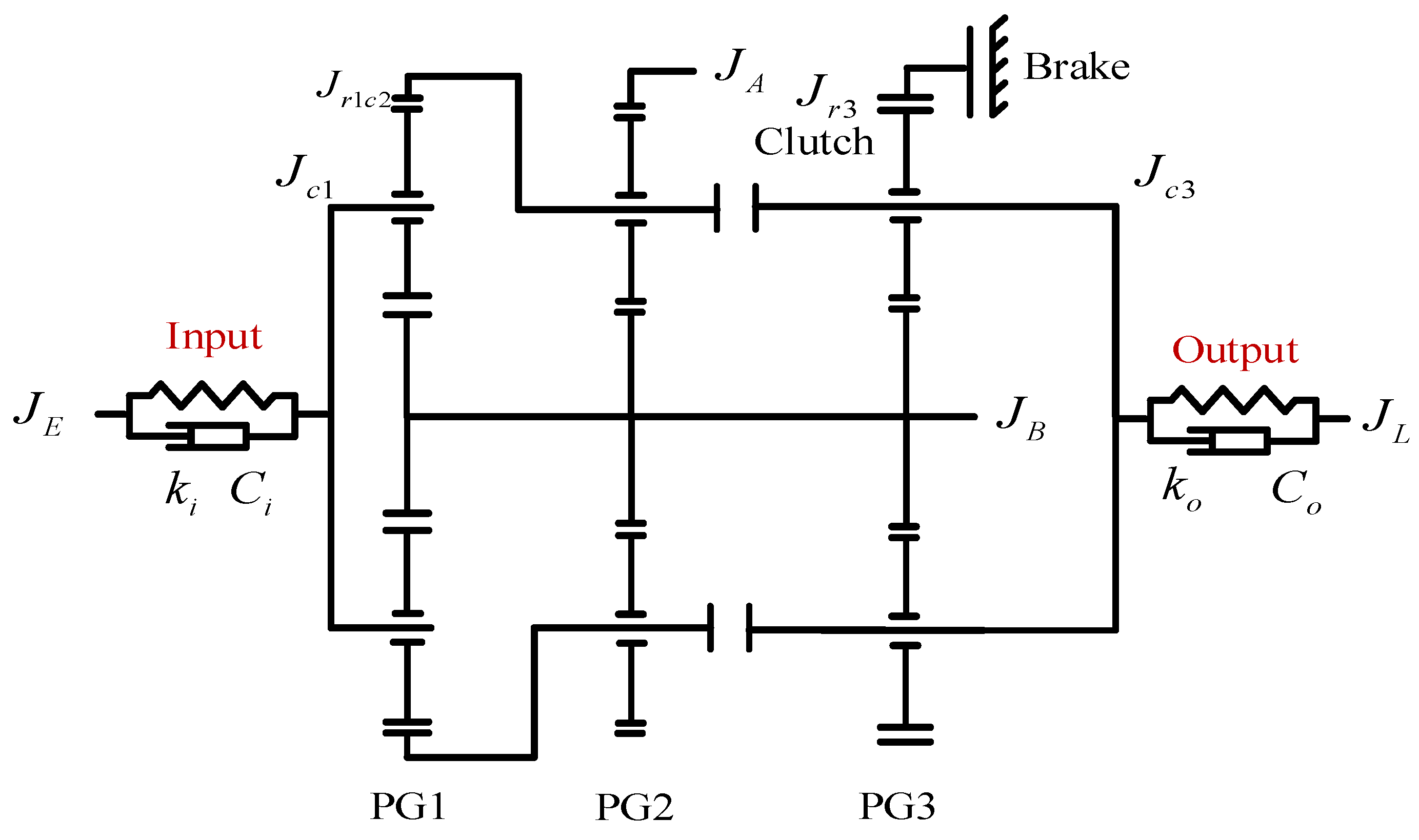
The driveline configuration of the investigated hybrid electric vehicle is illustrated in Figure 1. The powertrain system comprises an engine, two motor-generators (MGa and MGb), and a power coupling mechanism. The coupling mechanism incorporates three planetary gear sets, with CL1 representing a multi-plate clutch and BK denoting a braking clutch. The planetary gear components are designated as follows: S—sun gear, R—ring gear, and C—planetary carrier. Additionally, CL0 serves as the engine disconnect clutch.
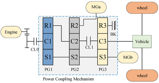
Figure 1.
Power-split-HEV driveline system.
The vehicle driveline has various operating modes, including two power-sharing modes (EVT, electrically variable transmission): input power-sharing mode (EVT1) and compound power-sharing mode (EVT2), as well as two power-concentrating modes: mechanical drive mode (MT) and pure electric drive mode (EV). The appropriate operating mode is selected according to the current driving requirements of the vehicle, and mode switching is realized by controlling the on–off of the clutch and brake.
The kinematic relationship between rotational speeds of planetary gear set components is expressed by the following equation:
where ns is the speed of the sun gear, nr is the speed of the ring gear, nc is the speed of the planetary carrier; k is the ratio of the number of teeth of the ring gear and the sun gear in the planetary mechanism.
In the two EVT modes, the speed relationship between the planetary row, engine, and motor in the power coupling mechanism is as follows:
The torque relationship between the components of the planetary gear mechanism is given in the following equation:
where Ts, Tr, and Tc represent the torque of the sun gear, ring gear, and planetary carrier, respectively.
The relationship between engine and vehicle speed and power coupling mechanism input speed and output speed is as follows:
where ωe is the engine speed, iq is the engine front transmission ratio, v is the vehicle speed, r is the wheel radius, and if is the reduction gear ratio.
Neglecting the friction between the components, the torque relationship in EVT1 and EVT2 modes can be obtained as follows:
where Ti, To, TA, TB denote the torque at the input end of the power coupling mechanism, the torque at the output end, and the torque of the motor A and motor B, respectively.
The relationship between the input torque and output torque of the engine, wheels, and power coupling mechanism is as follows:
where Te is the engine torque and Tw is the torque on the wheel.
2.1.2. Engine Torque Modeling and Motor Torque Modeling
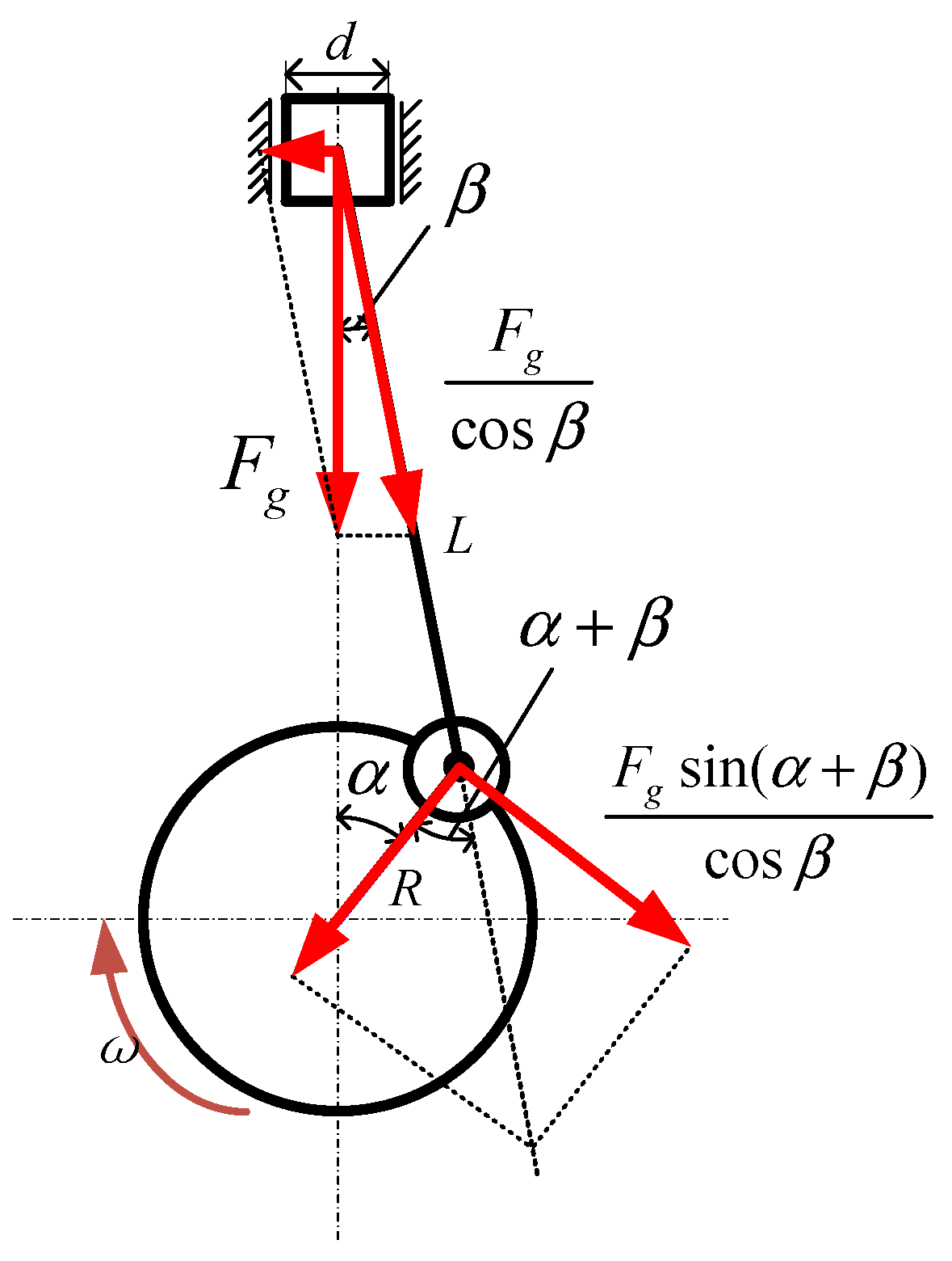
The engine produces periodic torque fluctuations during operation, which represent the primary excitation source for driveline vibrations. The total engine torque comprises two principal components: the gas pressure torque and the reciprocating inertia torque. Figure 2 illustrates the force distribution acting on the engine’s crank-slider mechanism [37].
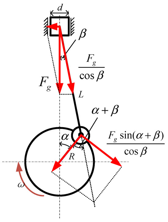
Figure 2.
Crank linkage mechanism force analysis.
The gas pressure torque and reciprocating inertia torque for a single-cylinder engine are expressed as follows:
where d is the cylinder diameter; p is the gas pressure in the cylinder; α is the crankshaft angle of rotation; β is the angle between the connecting rod and the centerline of the cylinder; R is the crank length; L is the length of the connecting rod; ω is the engine rotational speed; mj is the mass of the reciprocating moving parts.
Therefore, the single-cylinder engine torque and total torque are as follows:
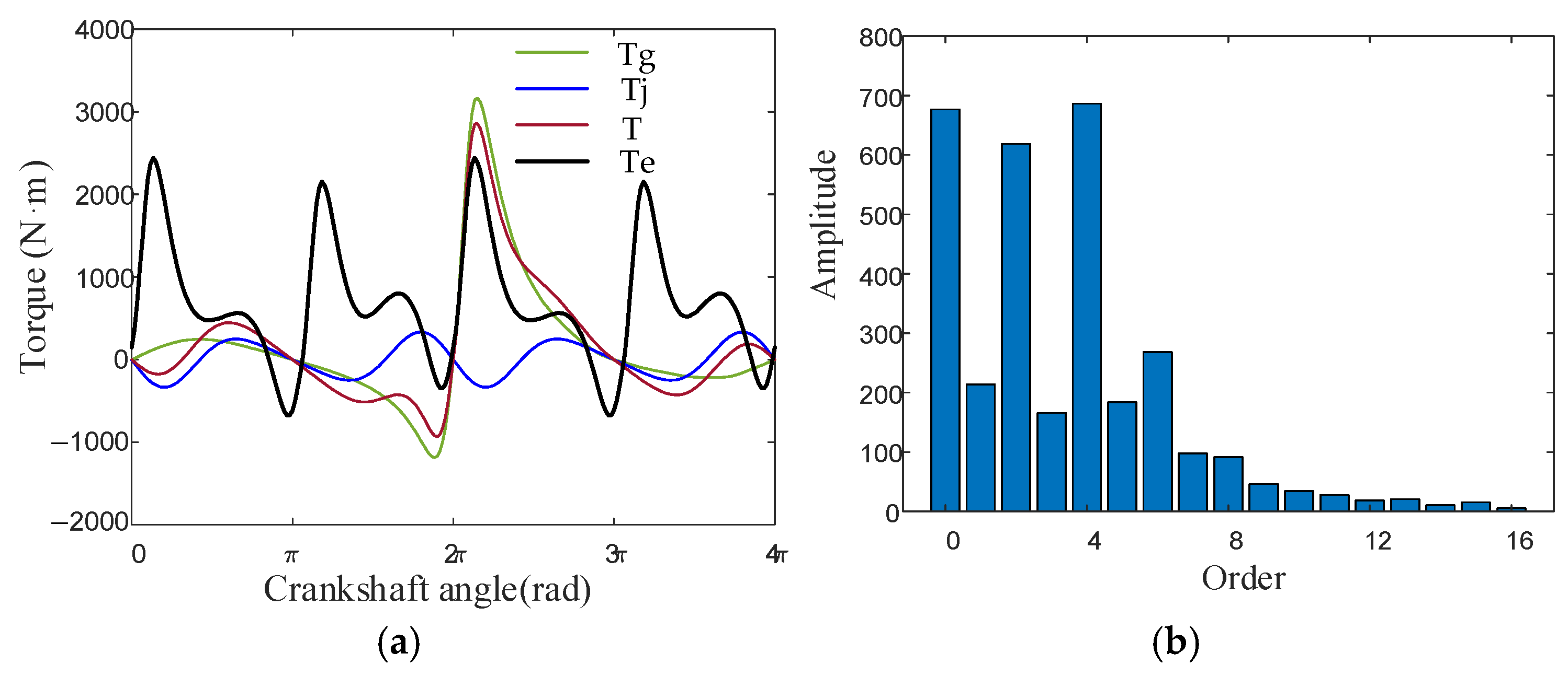
The engine excitation characteristics were simulated using a four-cylinder engine model operating at 2200 rpm. Figure 3a presents the output torque versus crankshaft angle curve, while Figure 3b displays the harmonic analysis results of the synthesized engine excitation torque. The analysis reveals that the 2nd and 4th harmonic components constitute the primary excitations responsible for driveline torsional vibration.

Figure 3.
Four-cylinder engine output torque at 2200 rpm. (a) Variation of engine excitation torque with angle of rotation; (b) harmonic analysis of engine torque.
The electric motor serves dual functions in the system: (1) primary propulsion and power generation, and (2) active torque actuation for torsional vibration suppression. Consequently, this study focuses on the motor’s output torque characteristics [9], which can be mathematically expressed as follows:
where TA, TB are the actual output torque of motor A and motor B, respectively; TA_cmd, TB_cmd are the torque control commands of motor A and motor B, respectively; τA, τB are the torque response time constants of motor A and motor B, respectively; nm is the motor rotational speed; Tm is the motor torque.
By conducting force analysis along the rotational direction, the vehicle’s dynamic equation is derived as follows:
where m is the mass of the vehicle, g is the gravitational acceleration, Rw is the wheel rolling radius, v is the vehicle speed, Tf is the rolling resistance moment, Tw is the air resistance moment, Tα is the gradient resistance, α is the slope angle of the road surface, Cd is the air resistance coefficient, and A is the windward area of the vehicle.
The target torque values for MGa and MGb can be derived from the constant-speed and torque relationships of transmission system components operating in EVT1 and EVT2 modes, expressed as follows:
where is the target torque of the engine, is the engine rotational speed, and , are the target torque of the MGa and MGb, iq is the engine front transmission ratio, and if is the output shaft to wheel ratio.
2.1.3. Transmission Mechanism Model
To address the control-strategy mismatch caused by oversimplified modeling, this study employs a model order reduction technique [38] to reconstruct the drivetrain system. Figure 4 illustrates the reduced-order dynamic model of the drivetrain obtained through this approach.
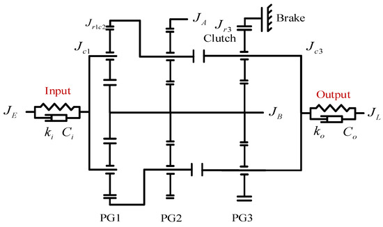
Figure 4.
Simplified diagram of the torsional dynamics model of the driveline.
The dynamic equations of the driveline system are established:
J1, J2, J3, J4 in the inertia matrix J are equivalent inertia with the following expressions:
The undamped free vibration dynamics equation of the system is as follows:
2.2. Torsional Vibration Mechanism Analysis
The free vibration response of a multi-degree-of-freedom system can be decomposed into a superposition of multiple simple harmonic modes. For a representative harmonic component with vibration response denoted as , the equation is derived as follows:
where ω is the intrinsic frequency of the system and X is the vibration mode of the system at the relevant intrinsic frequency.
Table 1 presents the first two natural frequencies of the system for both EVT1 and EVT2 operational modes.

Table 1.
Driveline intrinsic frequency (Hz).
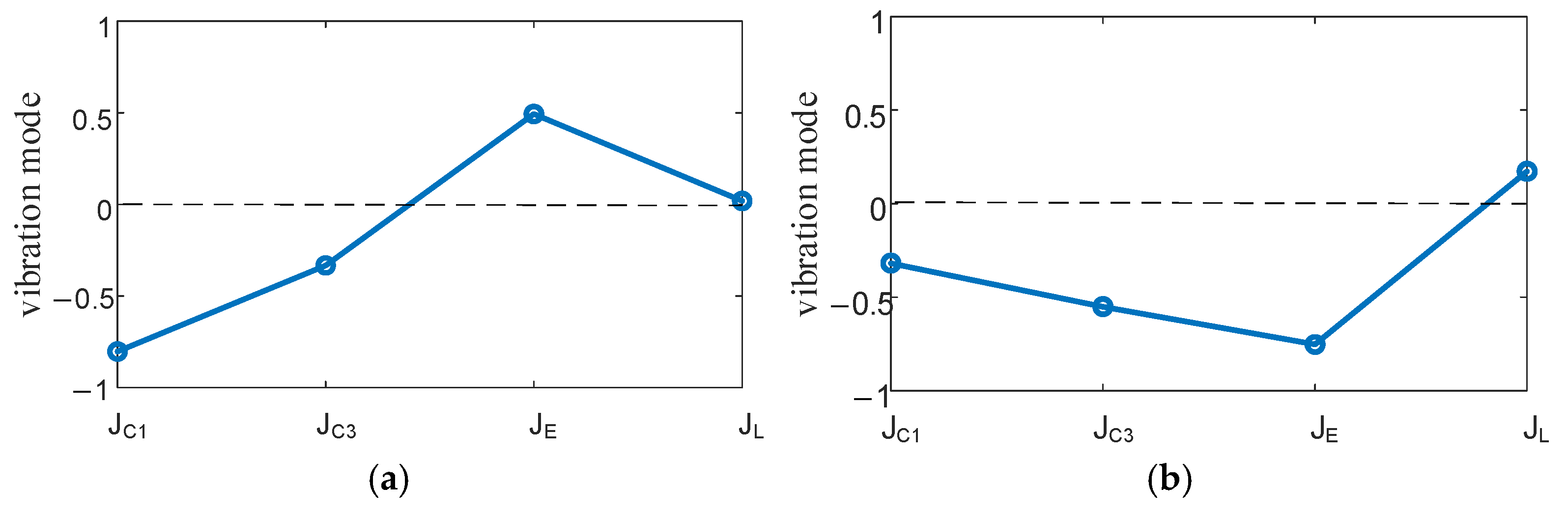
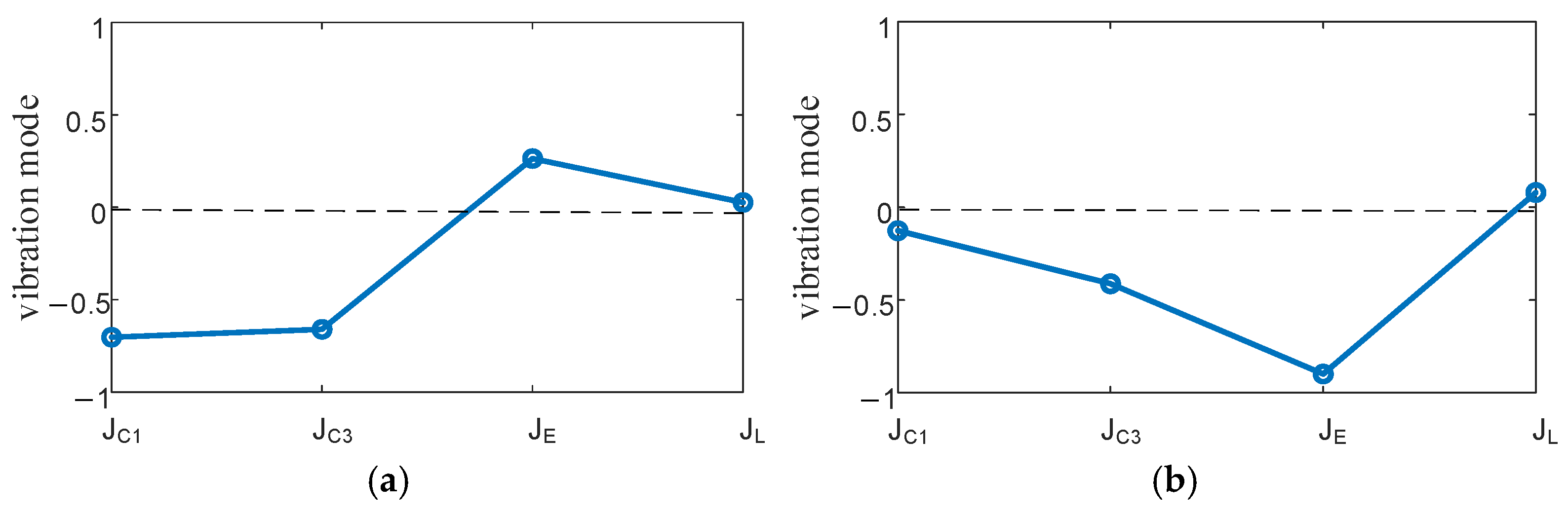
Figure 5 and Figure 6 respectively depict the first- and second-order vibrational modes of the driveline during EVT1 and EVT2 operation.
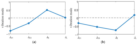
Figure 5.
EVT1 mode. (a) First-order vibrational mode (f1 = 17.55 Hz), (b) second-order vibrational mode (f2 = 37.43 Hz).
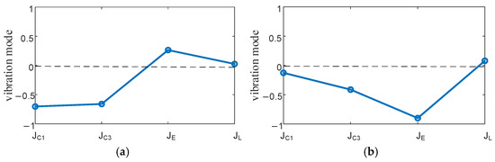
Figure 6.
EVT2 mode. (a) First-order vibrational mode (f1 = 21.40 Hz), (b) second-order vibrational mode (f2 = 44.19 Hz).
2.2.1. Analysis of Torsional Vibration Mechanism in Hybrid Mode
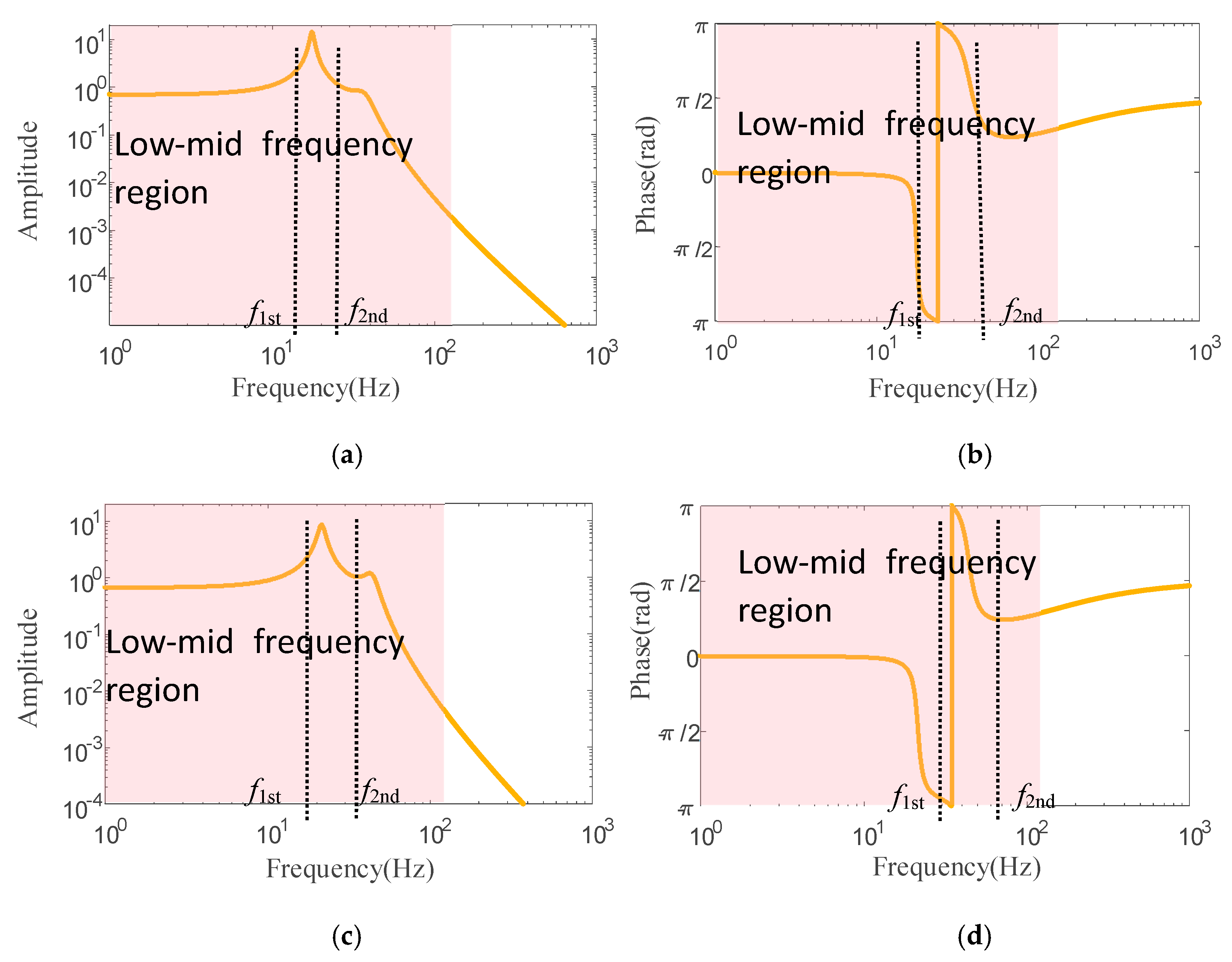
Frequency response characteristics were systematically analyzed and validated for both EVT1 and EVT2 operational modes, tracing the transmission path from engine torque excitation to output shaft torque response. As illustrated in Figure 7, the light-shaded region highlights the frequency band of primary interest for low-to-medium frequency torsional vibrations, with fundamental modal frequencies explicitly labeled as f1st and f2nd.
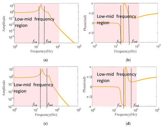
Figure 7.
Comparison of frequency characteristics between EVT1 and EVT2 modes, (a) amplitude-frequency characteristic of EVT2 mode, (b) phase-frequency characteristic of EVT2 mode, (c) amplitude-frequency characteristic of EVT2 mode, (d) phase-frequency characteristic of EVT2 mode.
The analysis reveals that the electromechanical hybrid driveline exhibits significant torsional vibration responses under low-to-medium-frequency excitations, while demonstrating attenuated responses in high-frequency regions. Consequently, active vibration control strategies should prioritize mitigation of low- and medium-frequency torsional vibrations.
2.2.2. Analysis of Torsional Vibration Mechanism in Pure Electric Mode
Under pure electric operating conditions, where Motor B serves as the sole propulsion source, the driveline dynamics can be effectively modeled as a two-inertia system (Figure 8).
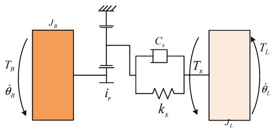
Figure 8.
Simplified model of the driveline.
The dynamic equations of the drive system at this point can be obtained as follows:
where , TB, JB are the rotational speed, torque, and moment of inertia of motor B; ir is the transmission ratio from motor B to the load planetary row; ks is the equivalent stiffness of the drive shaft, Cs is the equivalent damping of the drive shaft, and Ts is the torque of the drive shaft; , TL, JL are the rotational speed, torque, and equivalent moment of inertia of the load.
Selecting the motor B torque TB as the control quantity, the motor B speed , load speed , and drive shaft torque Ts as the state quantities, and as the output quantities, and the load torque TL as the perturbation quantity, the following can be obtained:
The state space equation of the driveline system is as follows:
In actual systems, the drive shaft exhibits non-rigid body behavior due to its inherent stiffness, which induces elastic deformation during power transmission. Variations in output inertia significantly affect system bandwidth, and this relationship directly influences transmission system torsional vibrations. To understand these interactions, a comprehensive analysis of the electric drive system’s dynamic response was conducted under varying stiffness and output inertia conditions. This investigation focuses on elucidating the fundamental mechanisms governing torsional vibration generation. The experimentally validated stiffness and inertia parameters used in this study are presented in Table 2.
Table 2.
Drive shaft stiffness and output inertia parameters.
Based on the mathematical relationship between state-space representations and transfer functions, the transfer function relating the control input to the system output can be derived from the state-space equations as follows:
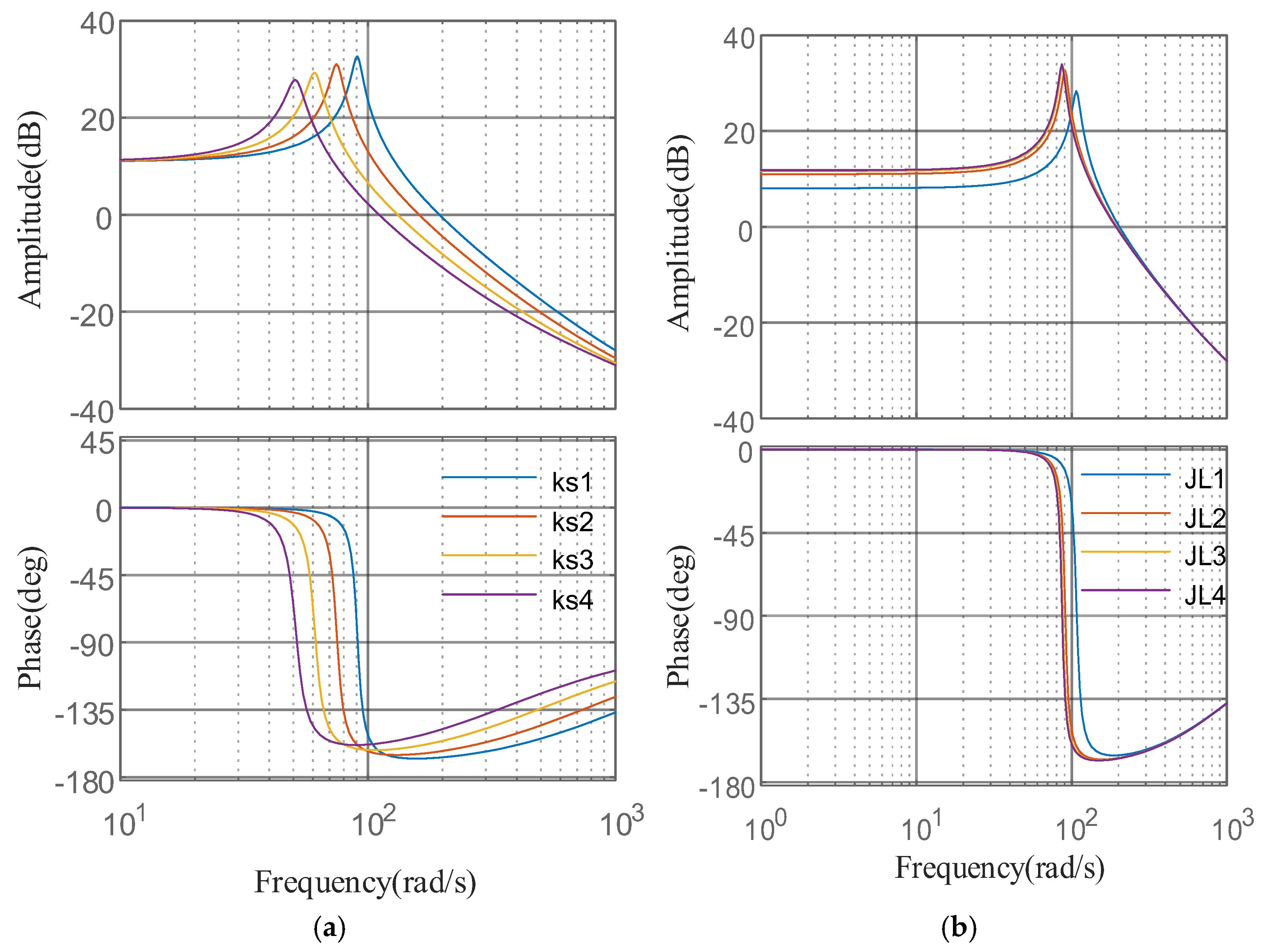
During pure electric operation, drive shaft torque fluctuations directly characterize driveline system vibrations. The transfer function relating Motor B torque to drive shaft torque is derived from Equation (26) as follows:
Using the parameter values for ks and JL specified in Table 2, the transfer function G1(s) was computed for various system configurations. The corresponding frequency response characteristics are presented in Figure 9.
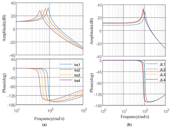
Figure 9.
G1(s) frequency response curve. (a) Stiffness change response, (b) load change response.
Figure 9a demonstrates significant amplitude and phase fluctuations in the transfer function of driveshaft torque (Ts) near the resonant frequency. These fluctuations exhibit a positive correlation with system stiffness—higher stiffness results in both increased resonant frequency and more pronounced fluctuations. As illustrated in Figure 9b, increasing the output-end inertia shifts the resonant frequency of Ts response toward mid-to-high-frequency ranges while simultaneously reducing amplitude. This behavior indicates improved torque smoothness and vibration attenuation under heavier loading conditions. During vehicle operation, external disturbances or operational condition changes may expand the system’s frequency bandwidth. If this expanded range encompasses the resonant frequency, intensified torsional vibration in the drivetrain system can occur. Therefore, active torsional vibration suppression methods become essential for maintaining system stability.
3. Torsional Vibration Control Strategy for HEV Based on Dual-Loop Decoupling Control
3.1. Dual-Loop Control Framework for Drivetrain Systems
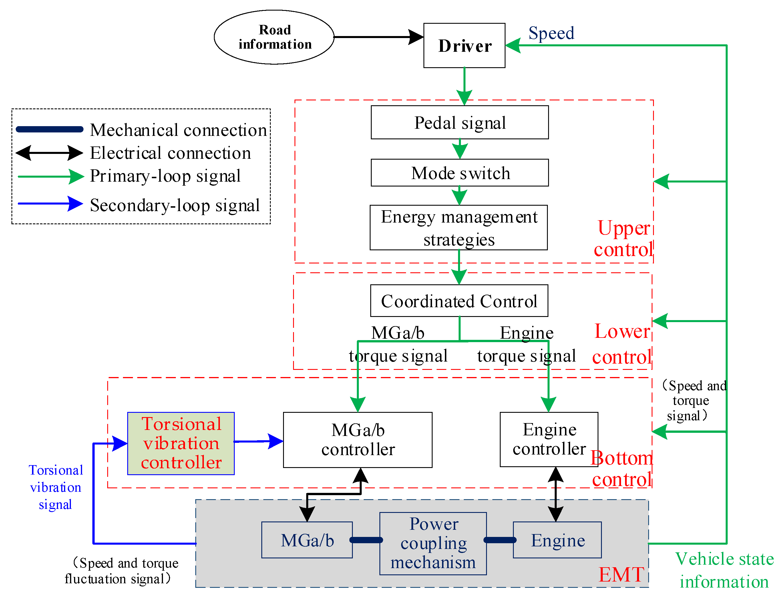
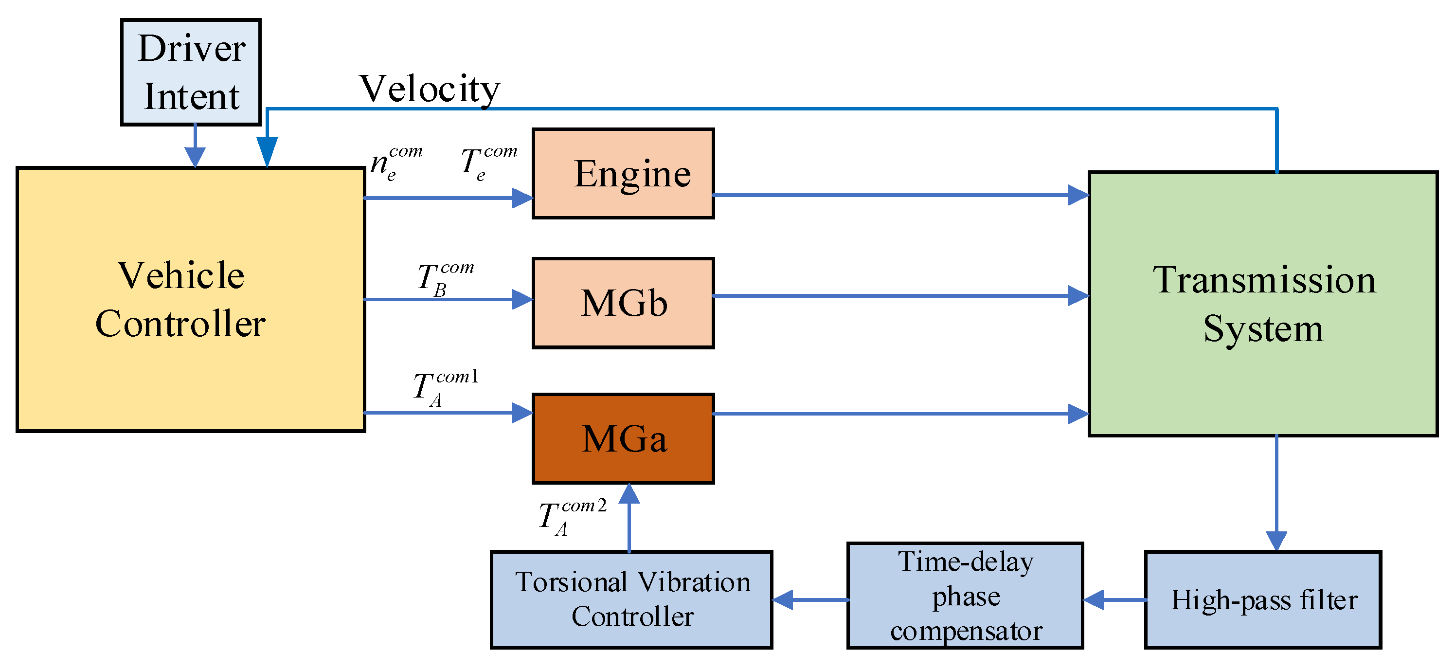
Building upon the existing integrated control strategy for the electromechanical transmission (EMT) system, this study proposes a hierarchical dual-loop motor control framework incorporating a dedicated torsional vibration control module (Figure 10). The architecture enhances conventional vehicle hierarchical control by adding a torsional vibration compensator to the motor controller. Due to its fast dynamic response characteristics, the vibration control module is strategically implemented at the bottom control layer, providing effective suppression of low-frequency drivetrain torsional vibrations while maintaining system stability.
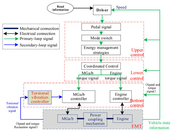
Figure 10.
Hierarchical dual-loop control framework for EMT systems.
As depicted in Figure 10, the conventional control system of the electromechanical transmission features a three-tier hierarchical architecture. The upper-level energy management layer optimizes power distribution to achieve balanced dynamic performance and fuel economy. The middle-level torque coordination layer ensures precise tracking of control targets, while the base-level torque response layer executes actuator command translation. Within this framework, we define (i) the primary control loop, integrating all three conventional control layers, and (ii) the secondary control loop, comprising the novel torsional vibration control module that performs real-time vibration signal processing and adaptive compensation torque calculation. These two loops converge through torque superposition at the base control layer, with the secondary loop specifically designed to inject anti-phase vibration cancellation torque while maintaining the primary loop’s operational integrity. This dual-loop architecture enables simultaneous achievement of both conventional control objectives and active vibration suppression.
The control process of the EMT system with torsional vibration suppression operates as follows: Initially, the pedal signal interpretation module converts accelerator inputs into total power demand based on real-time vehicle states. Subsequently, the mode transition module selects the optimal EVT mode according to vehicle speed and pedal position. The energy management system (EMS) then allocates the total power demand between the engine and battery, while transmitting both the power distribution scheme and system state references to the coordinated control module in the lower-level controller. This module dynamically optimizes the torque targets for Motor A, Motor B, and the engine by integrating operational state feedback, ensuring rapid and stable achievement of the EMS objectives. Finally, the adjusted reference torque signals are distributed via CAN bus to the motor and engine controllers. Simultaneously, the torsional vibration control module executes active damping algorithms using real-time vibration data to generate compensatory torque signals. These coordinated actions enable seamless actuator control for smooth vehicle propulsion while effectively suppressing driveline oscillations.
3.2. Frequency-Domain Decoupling Method for Dual-Loop Control of Motor
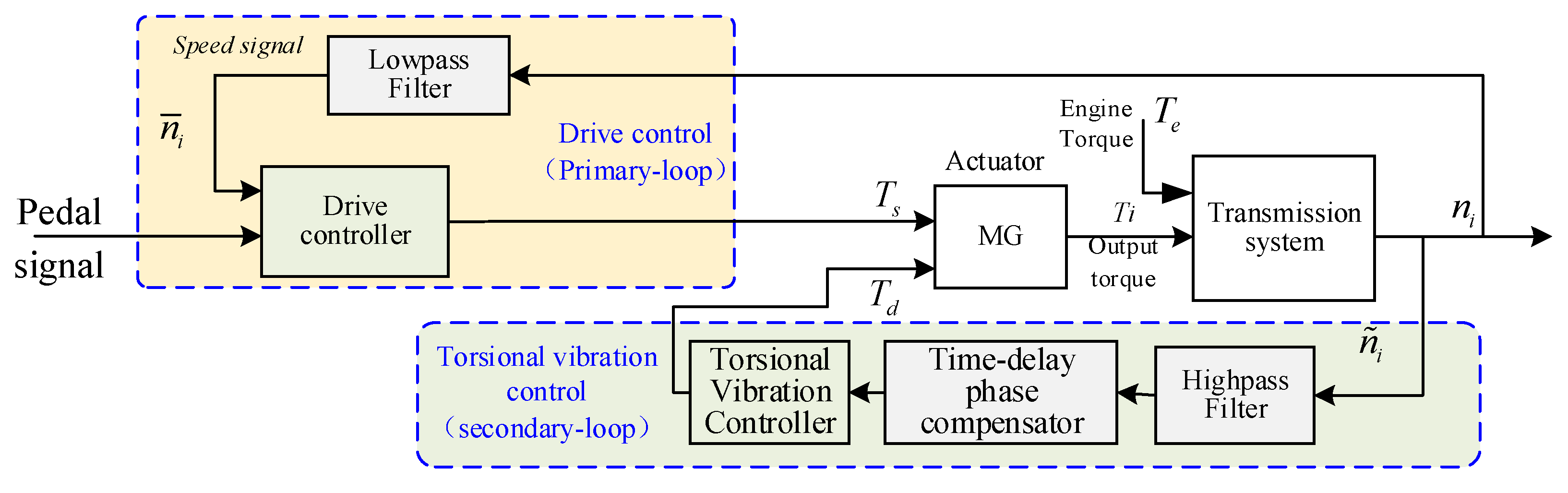
In electromechanical hybrid transmission systems, the introduction of a torsional vibration control loop results in the motor output torque comprising both drive control and torsional vibration suppression components. During actual operation, however, the interaction between vehicle drive control and active torsional vibration control deteriorates system stability and weakens robustness [36]. To address this issue, this study proposes a feedback-filter-based decoupling method for dual-loop motor control in electromechanical hybrid transmission systems, as illustrated in Figure 11. The core idea involves integrating a filter into the feedback loop to achieve frequency-domain decoupling between the drive control (primary-loop) and torsional vibration control (secondary-loop).
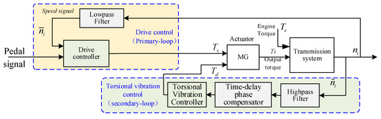
Figure 11.
Diagram of the dual-loop control decoupling method for motors based on feedback filtering.
Figure 11 illustrates that the primary-loop drive controller exhibits low-frequency characteristics, responding only to the operational signal, while the secondary-loop torsional vibration controller demonstrates high-frequency characteristics, acting solely on high-frequency torsional vibration signals. Under closed-loop dynamic operation, the main and secondary-loop controllers exhibit coupling behavior, which can be decoupled in the frequency domain under specific conditions to achieve independent control. For clarity, this study distinguishes the feedback signals of the primary and secondary control loops: the filtered feedback signal for system drive control is defined as the operational signal, representing non-periodic speed and torque signals determined by the vehicle’s driving demands under steady-state conditions; the filtered feedback signal for torsional vibration control is defined as the output torsional vibration signal, comprising zero-mean periodic disturbances such as speed and torque fluctuations. To extract these signals, low-pass and high-pass filters are employed in this work.
Sensitivity Analysis of Controllers
This study employs a frequency response sensitivity analysis method to derive the decoupling conditions for the primary and secondary control loops of the system. The torque output module and the drive control module in the main loop channel (Figure 11) are consolidated and represented as a dual-loop motor control schematic, as illustrated in Figure 12.
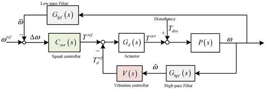
Figure 12.
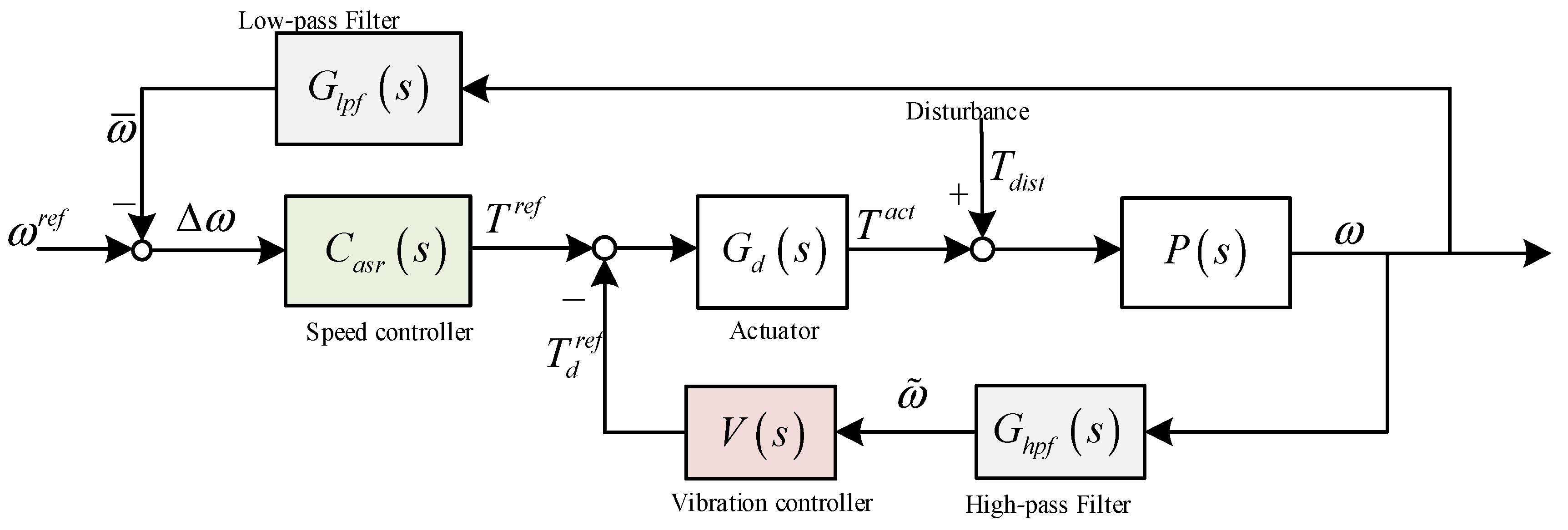
EMT speed closed-loop control structure with torsional vibration control loop.
In Figure 12, is the EMT system, is the transfer function of the speed controller. is the dynamic response of the actuator, which has hysteresis and can usually be approximated as a first-order inertial link. is the low-pass filter, which is used to estimate the mean value of output speed. is the high-pass filter, which is used to estimate the speed fluctuation. is the torsional vibration controller. Obviously, the following inequality constraints exist.
It can be seen from Figure 12 that in the closed-loop speed regulation system, the transfer function from to is as follows:
The sensitivity of to the speed controller is
The sensitivity of to the vibration controller is
Define the relative sensitivity of speed control :
It is known from Equation (28) that
Assume that , then . In addition, , therefore
Note 1: , that is, the torsional vibration controller has little influence on the speed regulation of the system. The transmission from torque disturbance to output speed is
The sensitivity of to the speed controller is
The sensitivity of to the speed controller is
Let s = jω, then
Equation (38) satisfies the following relationship:
Note 2: is related to the frequency of torque disturbance . When the jω is small, is large. At this time, the regulation controller has a great impact on torsional vibration. When the frequency is high, the control controller has little effect on torsional vibration. In particular, when jω is greater than the stopband frequency of the low-pass filter, ≈ 0, the control controller has no effect on the torsional vibration.
Combined with Note 1 and Note 2: when the frequency of engine torque fluctuation is large, speed regulation control and torsional vibration control are independent of each other. Therefore, the control parameters do not affect each other.
By synthesizing Equations (34) and (38), the sufficient conditions for frequency-domain decoupling of the primary and secondary controllers can be summarized as the following three constraints, which must be simultaneously satisfied (as illustrated in Figure 13):
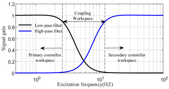
Figure 13.
Decoupling conditions for primary and secondary controllers in EMT system.
① The primary and secondary control loops are decoupled in the frequency domain;
② The relative sensitivity of the torsional vibration controller approaches zero within the operational frequency band of the primary controller;
③ The relative sensitivity of the drive controller approaches zero within the operational frequency band of the secondary controller.
As illustrated in Figure 11 and Figure 13, the low-pass filter suppresses the amplitude of torsional vibration signals in the drive controller within the low-frequency range of the primary controller’s operation, thereby achieving torsional vibration isolation. Conversely, in the high-frequency range governed by the secondary controller, the high-pass filter attenuates the amplitude of operational signals in the torsional vibration controller, enabling effective operational isolation. In the transitional frequency band between the primary and secondary controllers’ operational ranges, the output signals of both controllers exhibit coupling. However, since the excitation torque in this frequency band has a significantly smaller amplitude compared to other ranges, its output response can be neglected. Consequently, the primary and secondary controllers maintain strong decoupling characteristics across the entire spectrum.
3.3. Active Torsional Vibration Suppression Method Based on Filtered RLS Algorithm
The design of the hybrid mode torsional vibration control framework with MGa as the actuator is shown in Figure 14.

Figure 14.
The hybrid mode torsional vibration control framework.
During the actual operation of the transmission system, the driving torque of the engine and motor is first calculated based on the energy management strategy. Subsequently, the torsional vibration state feedback is utilized to decouple the primary and secondary controllers through a filter. To address computational delays in the control algorithm, a time-delay phase compensation method is adopted [39], where a phase compensator is connected in series with the torsional vibration controller. This approach effectively eliminates phase lag errors, thereby reducing the amplitude of torque fluctuations and ensuring stable operation of the powertrain. Finally, the torsional vibration controller computes the compensation torque for Motor A to actively suppress torsional vibrations in the transmission system.
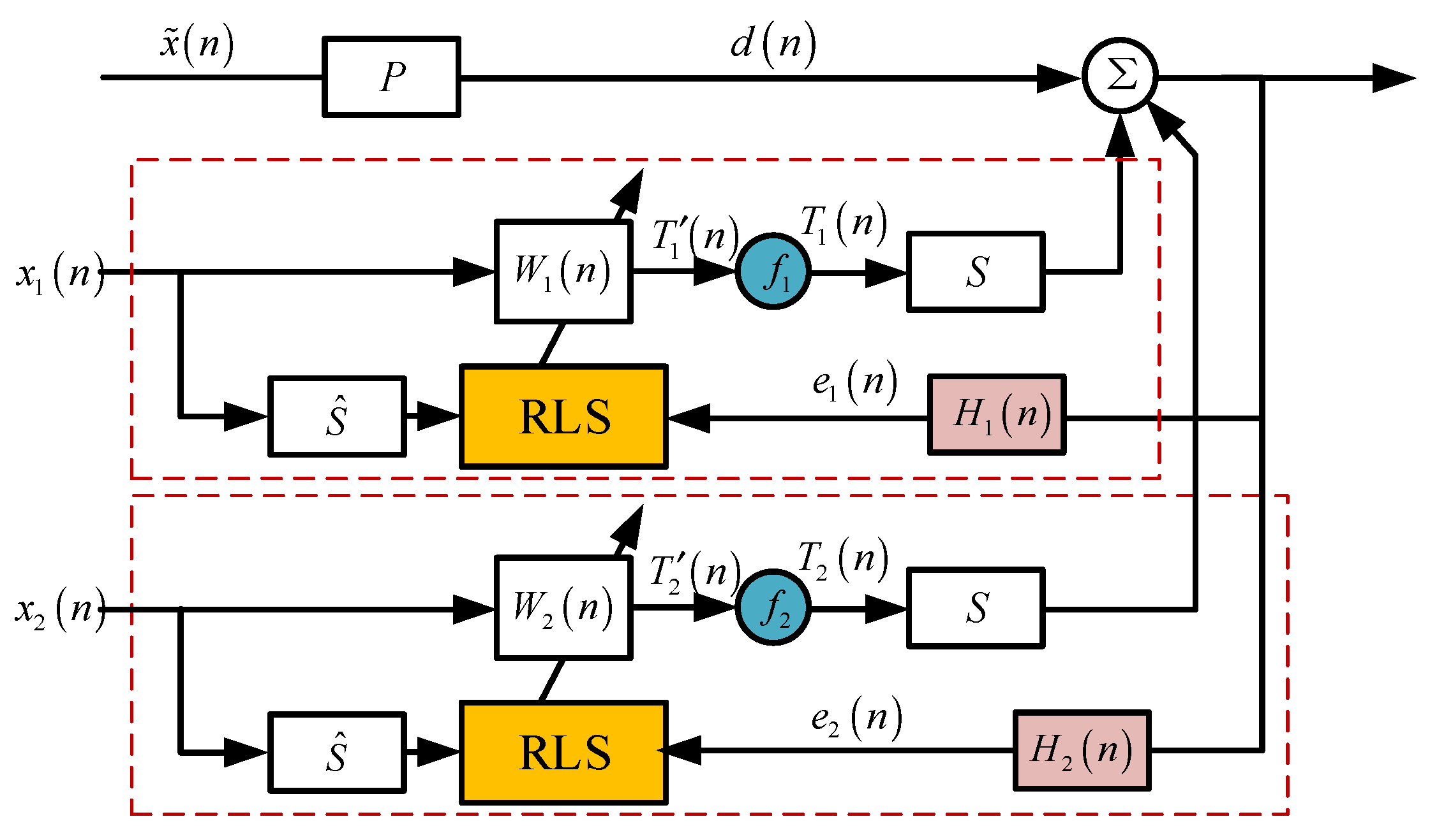
This study presents an adaptive active control method for torsional vibration suppression utilizing a filtered recursive least-squares (RLS) algorithm. During system operation, torque fluctuations generated by both the engine and electric motor propagate through drivetrain components to the control point, undergoing amplitude and phase modulation throughout the transmission process. Within the active control framework, the transmission path from the engine to the control point is designated as the primary path (P), while the path originating from the motor is defined as the secondary path (S).
As illustrated in Figure 15, represents the harmonic excitation signal generated by the engine, containing multiple frequency components correlated with the engine rotational frequency. This signal propagates through the primary channel P to the driveshaft, producing the vibrational response d(n). and denote reference signals corresponding to the second- and fourth-order harmonics of the engine rotational frequency, respectively. and are the output shaft torsional vibration signals at these respective harmonic frequencies. corresponds to the controller’s weighting coefficient. f indicates the torsional vibration control intensity. and represent the initial motor torque and compensated torque command, respectively. and are the resonator transfer functions.

Figure 15.
Adaptive torsional vibration control block diagram.
Given that the second- and fourth-order harmonics of the engine’s rotational frequency represent dominant resonant components in the system, these frequency components are selected as reference signals for torsional vibration control. The corresponding vibration controllers are specifically designed for these two critical frequencies as follows:
where , f0 is the reference frequency and ρ is the pole contraction factor, .
The weight coefficients W(n) are iteratively computed based on both input signals and feedback error signals of the control variables. This computation incorporates errors from both current and past time instants, with the cost function defined as follows:
where λ is the forgetting factor, taking the value range of 0~1.
The above equation partializes W(n) and makes the result zero; we have the following:
Through the above derivation process, the filtered RLS algorithm recursive calculation formula can be obtained as follows:
3.4. Active Torsional Vibration Suppression Method Based on ADRC Algorithm
In pure electric mode, only MGb is operational. Therefore, torsional vibration active control is achieved through torque compensation implemented by MGb. Figure 16 presents the designed control framework for torsional vibration in hybrid pure electric mode.
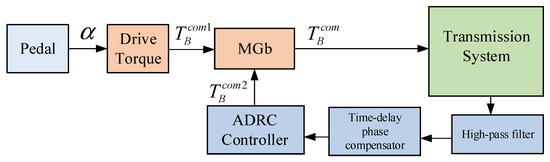
Figure 16.
The pure electric mode torsional vibration control framework.
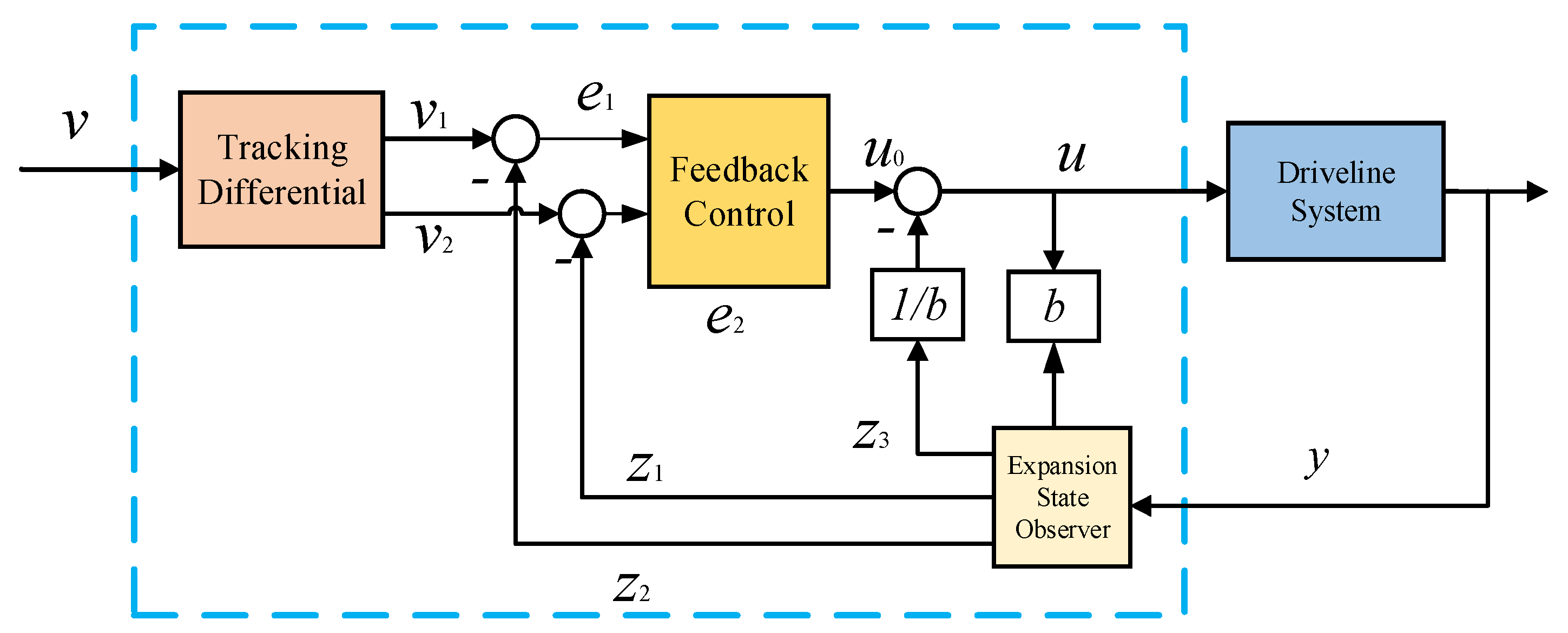
This study implements the ADRC algorithm to actively suppress torsional vibrations in pure electric drive mode operations. Figure 17 presents the architecture of the ADRC algorithm. The proposed torsional vibration controller comprises three key components: (1) a tracking differentiator, (2) a state observer, and (3) an error feedback control module. The reference input signal v represents the output shaft rotational speed. The tracking differentiator generates two derived signals: v1 (tracking v) and v2 (tracking its differential). The state observer provides estimated values z1 and z2 for v1 and v2, respectively. The control algorithm operates as follows: First, the preliminary torque command u0 for Motor B is computed based on the observed errors. Subsequently, the state observer estimates the torsional vibration in the output shaft, enabling correction of the control command to the final value u, which is then applied to the drivetrain system.
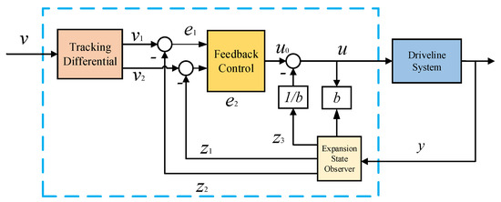
Figure 17.
ADRC framework.
In the studied hybrid electric vehicle operating in pure electric mode, the ADRC controller receives the desired drive torque (determined by current throttle position) as its input, while the drivetrain control variable corresponds to the motor torque command. Regarding driveline torsional vibration mitigation during operation, the driveshaft vibration signal represents a measurable system disturbance that can be actively monitored and compensated through the control system.
Construct the speed tracking differentiator as follows:
where v* is the input signal of the tracking differentiator, which is the reference speed of the transmission system, and v1 is the tracking signal of v; fal (e0, α0, δ0) is the optimal control function, and e0 is the error between the reference signal and the tracking signal; α0 is the tracking factor, r0 is the speed factor, and δ0 is the filtering factor, which is an adjustable parameter of the algorithm.
A state expansion observer is designed to estimate both the output speed (y) and output shaft torsional vibration of the transmission system. The observer outputs, denoted as z1 and z2 respectively, are mathematically expressed as follows:
where e1 is the error signal, β1 and β2 are the ESO output error correction gains, α1 and α2 are the tracking factors, δ1 and δ2 are the filtering factors, and b is the compensation factor.
An integrated torsional vibration control strategy is developed by synthesizing a speed tracking differentiator with an extended-state observer for torsional vibration monitoring. This nonlinear feedback control system actively suppresses transmission system vibrations, governed by the following expression:
where e2 is the error signal, α3 is the tracking factor, δ3 is the filtering factor, b0 is the compensation factor, and k is the regulator gain, all of which are adjustable parameters of the controller.
4. Simulation and Result Analysis
4.1. Analysis of the Effect of Active Torsional Vibration Suppression Under Hybrid Drive Conditions
4.1.1. Constant-Speed Working Condition Analysis
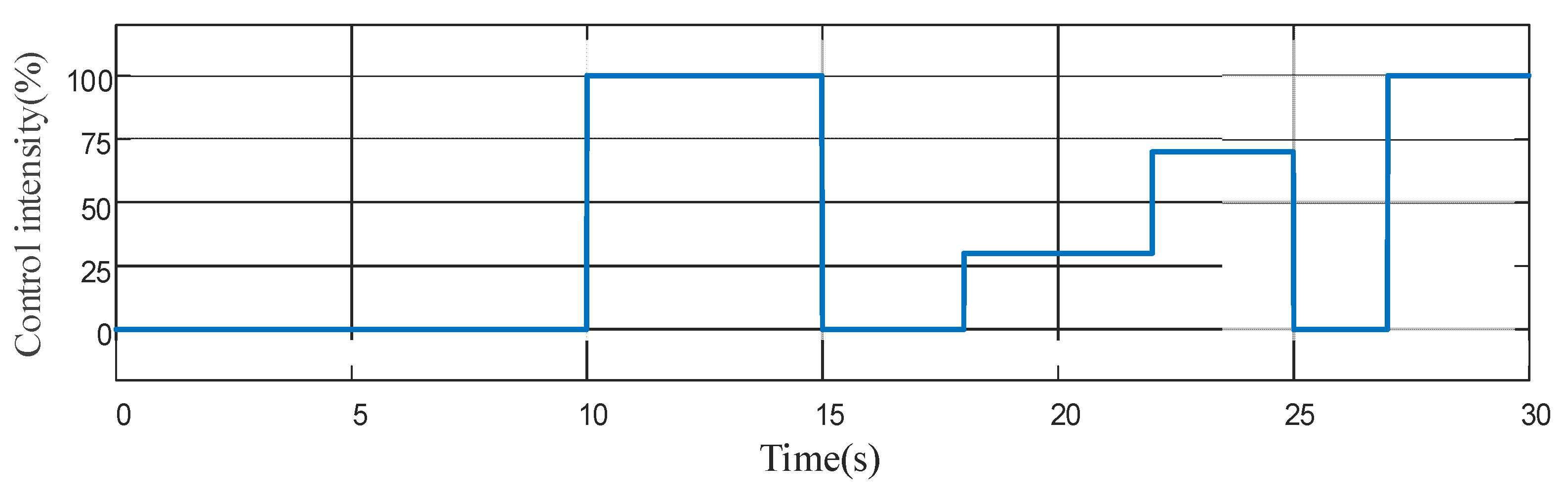
To validate the proposed adaptive active vibration suppression algorithm, numerical simulations were conducted under constant-speed EVT2 mode operation with an engine speed of 1200 rpm. The simulation protocol consisted of two phases: (1) a 10 s baseline operation without vibration control, followed by (2) a 20 s controlled operation with progressively varying control intensity (as illustrated in Figure 18). This approach enables systematic evaluation of the control algorithm’s effectiveness across different suppression intensities.
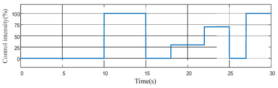
Figure 18.
Control intensity—f(%).
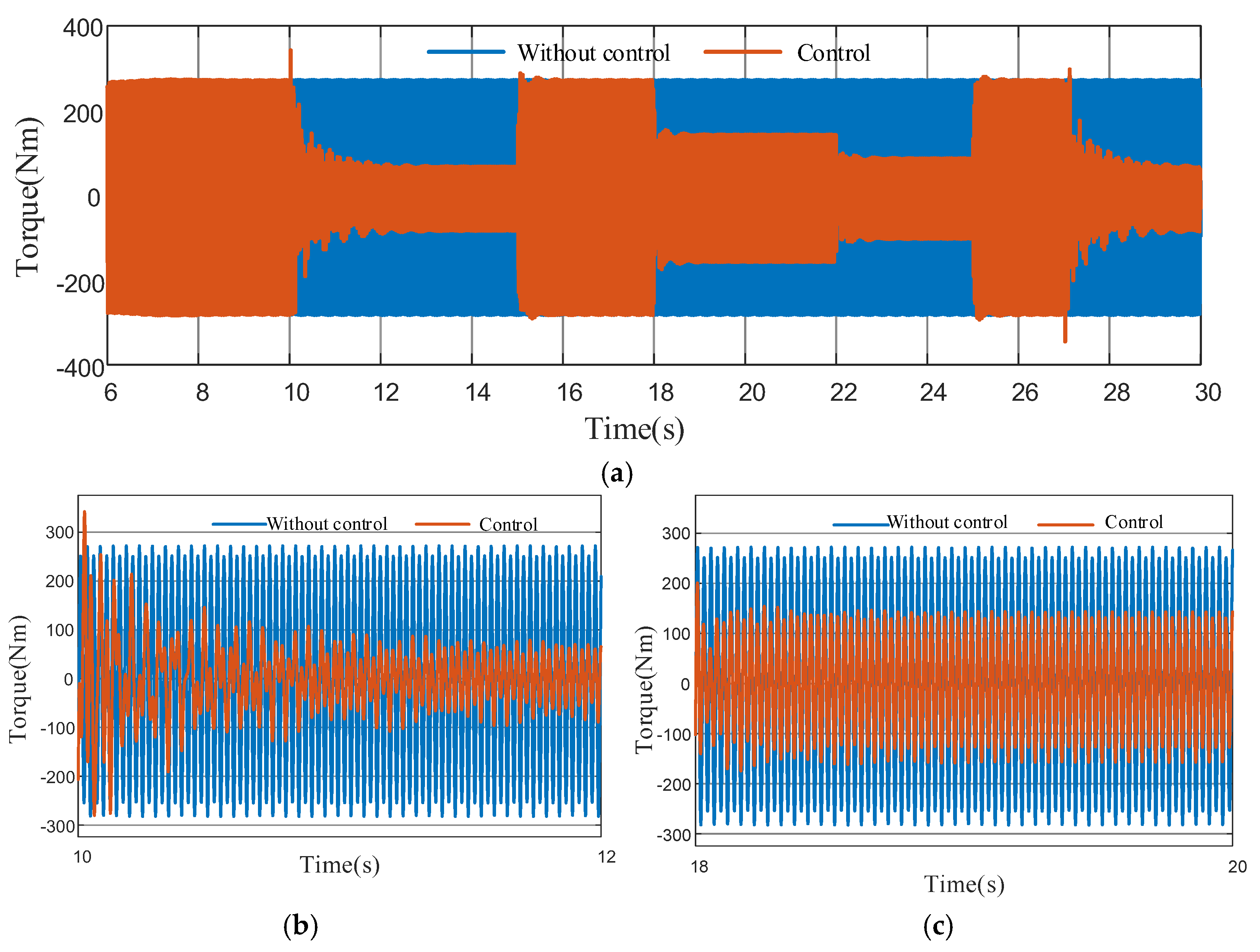
Figure 19 illustrates the variation in output shaft torque fluctuations during the control process. The results demonstrate a significant reduction in torque vibration amplitude following the application of adaptive torsional vibration control. Furthermore, the simulation results reveal a positive correlation between (1) the control intensity, (2) the output shaft torque vibration attenuation amplitude, and (3) the actual active torsional vibration suppression torque generated by the motor.
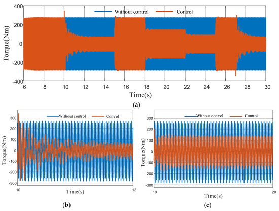
Figure 19.
Output shaft torque fluctuation. (a) Full process torque variation, (b) control intensity-f = 100%, (c) control intensity-f = 30%.
Figure 19b demonstrates that applying active torsional vibration suppression torque to the driveline system achieves a 72.2% reduction in output shaft torque amplitude, decreasing from 270 Nm to 75 Nm when maximum control intensity is implemented.
Simulation results under steady-state engine operation confirm the effectiveness of the proposed adaptive active suppression strategy. The system exhibits significant attenuation of torque fluctuations in the output shaft, while maintaining the flexibility to adjust control intensity according to operational requirements. This adaptive capability ensures optimal balance between vibration control and driveline performance. The simulation data provide conclusive evidence of the algorithm’s efficacy in torsional vibration mitigation.
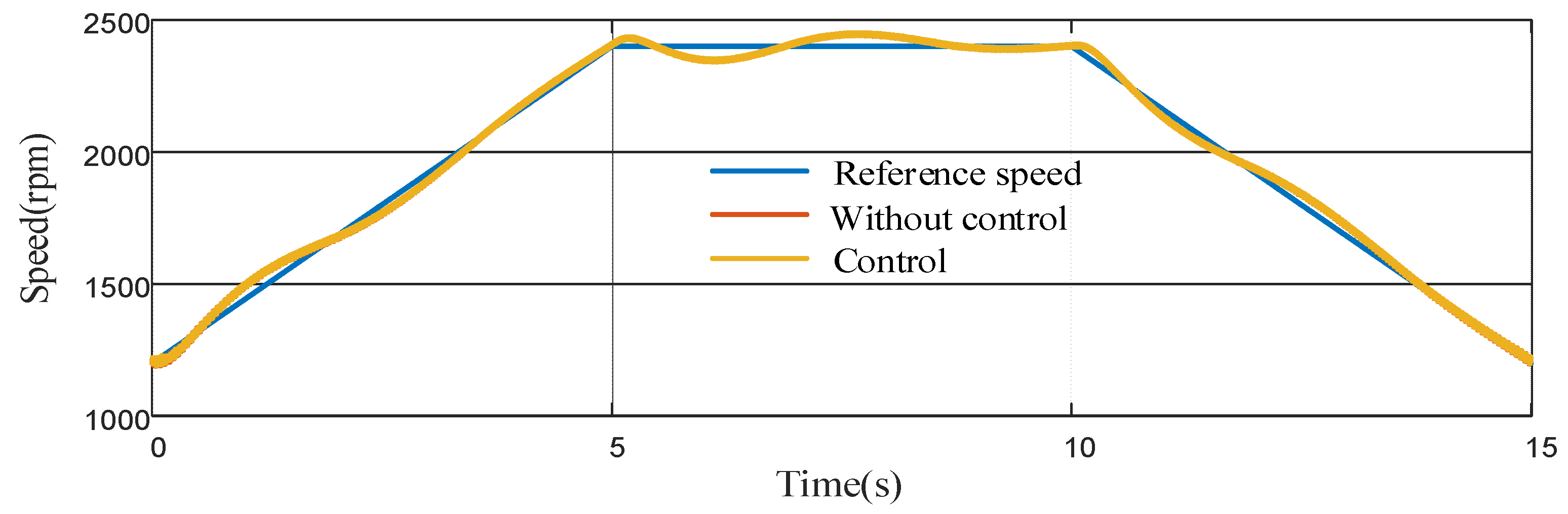
4.1.2. Variable-Speed Working Condition Analysis
The shifting condition simulation employs the EVT1 mode as a representative case study. In this configuration, the engine operates under sweep conditions, with its rotational speed profile illustrated in Figure 20. The motor drives the engine, accelerating it from rest to 2400 rpm at t = 0, followed by a 5 s stabilization period before deceleration to 1200 rpm. The results demonstrate that the engine speed maintains stable tracking of the reference trajectory both before and after implementation of the active vibration suppression system.
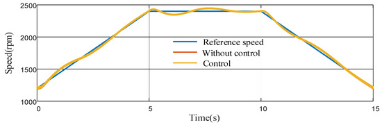
Figure 20.
Engine speed.
Figure 21 compares the driveline output shaft’s torsional vibration characteristics before and after implementing active suppression control. The results reveal three distinct behavioral phases: (1) During transient engine operations (0–5 s acceleration; 10–15 s deceleration), significant vibration amplitudes occur, while steady-state operation (5–10 s) exhibits reduced vibration levels, with active control demonstrating substantial attenuation throughout all phases (Figure 21a). (2) Initial control implementation (0–2 s) shows heightened vibration due to transient conditions, where the adaptive algorithm’s finite convergence time causes a brief amplitude increase before achieving effective suppression (Figure 21b). (3) During speed stabilization (4–6 s), vibration amplitudes decrease compared to the uncontrolled case, though a torque discontinuity emerges at 5 s when engine acceleration ceases, as visible in the local magnification (Figure 21c). The control system’s transitional response to this operational change confirms its dynamic compensation capability.
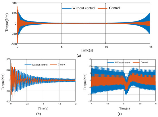
Figure 21.
Output shaft torque fluctuation, (a) full process torque variation, (b) partial view 1, (c) partial view 2.
The simulation results demonstrate successful active suppression of torsional vibrations within the transmission system. The proposed control algorithm exhibits stable damping performance, achieving significant attenuation of torsional vibrations. These findings validate the efficacy of the implemented filtered RLS adaptive control algorithm in vibration mitigation.
4.2. Analysis of the Effect of Active Torsional Vibration Suppression Under Pure Electric Drive Conditions
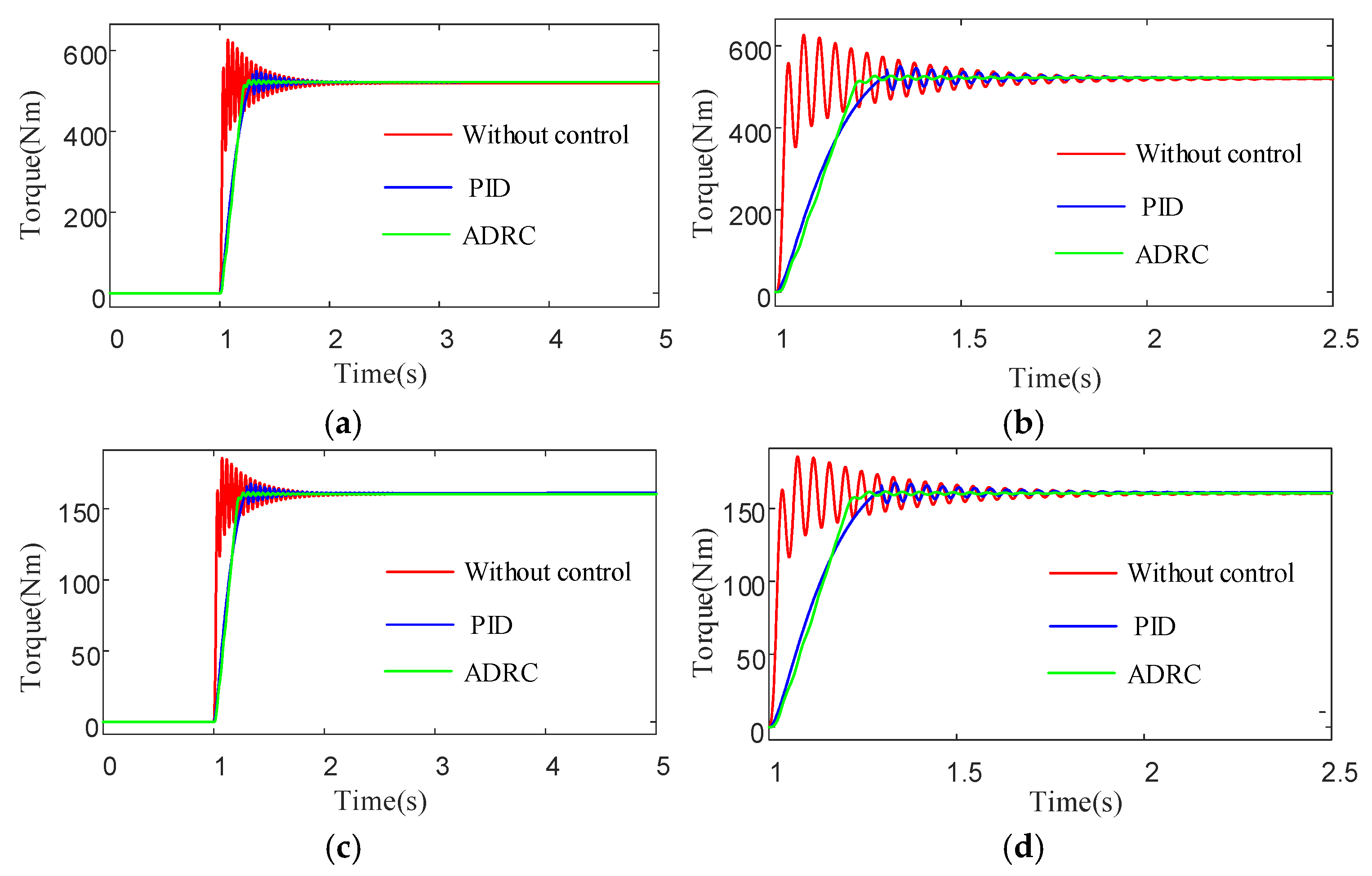
4.2.1. Analysis of Start-Up Acceleration Condition
A start-up acceleration scenario was simulated over a 5 s duration, beginning with the vehicle at rest. The electric motor was activated at t = 1 s to initiate vehicle acceleration. Figure 22 compares the torque simulation results under three control strategies: no vibration control, PID control, and ADRC. As evidenced in Figure 22a,c, all three control approaches achieved stable motor torque and output shaft torque by the end of the simulation. Notably, the ADRC method demonstrated superior transient response characteristics compared to conventional PID control, with significantly reduced oscillation amplitudes during the acceleration phase.

Figure 22.
Simulation results of torque characteristics during start-up acceleration, (a) output shaft torque, (b) partial view, (c) electric motor-B torque, (d) partial view.
As evidenced by the magnified views in Figure 22b,d, the ADRC strategy demonstrates superior torsional vibration suppression performance. The output shaft torque reaches steady-state within 0.7 s under ADRC control, representing a 70% reduction in stabilization time compared to the uncontrolled case. Furthermore, comparative analysis reveals that the ADRC approach achieves more effective vibration attenuation than conventional PID control during the startup process.
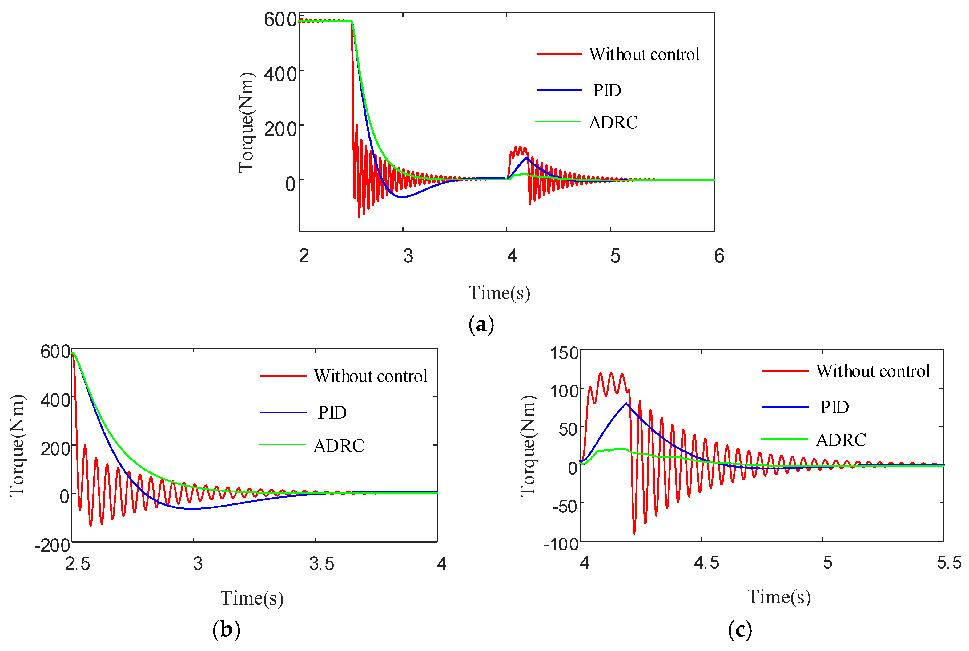
4.2.2. Analysis of Rapid Deceleration Conditions
A numerical simulation was conducted to investigate vehicle dynamics during emergency deceleration, with a total duration of 6 s. The simulation initializes with the vehicle in constant speed condition. At t = 2.5 s, complete throttle release is implemented, followed by brake pedal application at t = 4.0 s. The results are presented in Figure 23 and Figure 24.
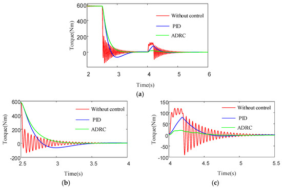
Figure 23.
Simulation results of output shaft torque characteristics. (a) Output shaft torque, (b) partial view 1, (c) partial view 2.
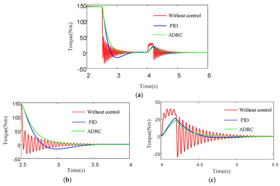
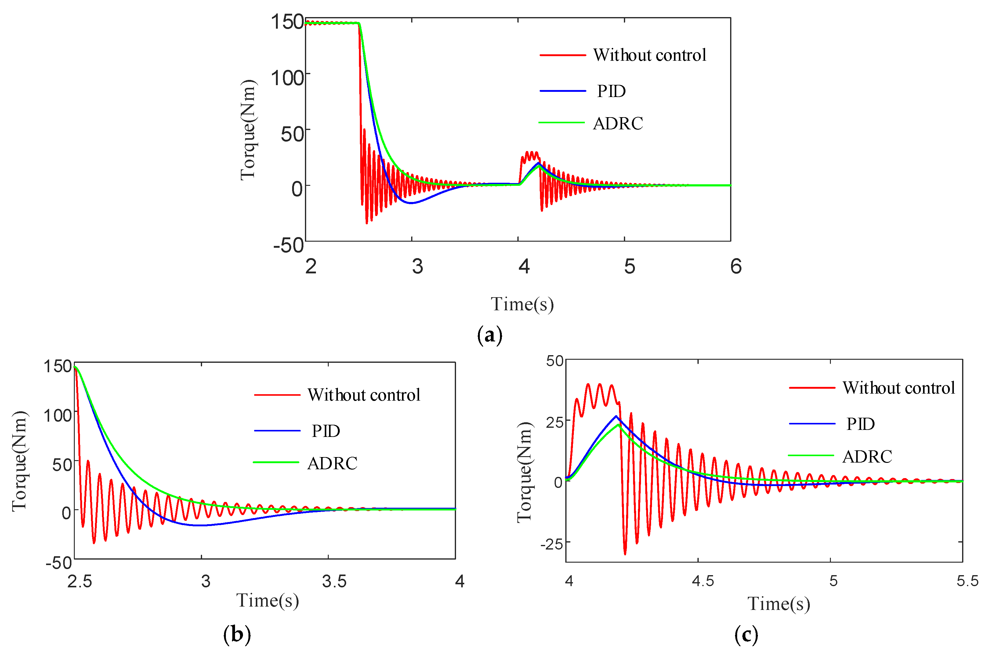
Figure 24.
Simulation results of electric motor-B torque characteristics. (a) Electric motor-B torque, (b) partial view 1, (c) partial view 2.
Figure 23 and Figure 24 demonstrate that the driveline’s demanded torque exhibits stepwise variations during transient throttle change conditions. While conventional PID control can partially mitigate torque fluctuations, significant oscillations and overshoot persist. In contrast, the proposed active torsional vibration suppression strategy based on ADRC achieves smooth torque transitions, effectively eliminating torque fluctuations and demonstrating superior vibration suppression performance.
5. HIL Validation of Active Torsional Vibration Suppression Algorithm
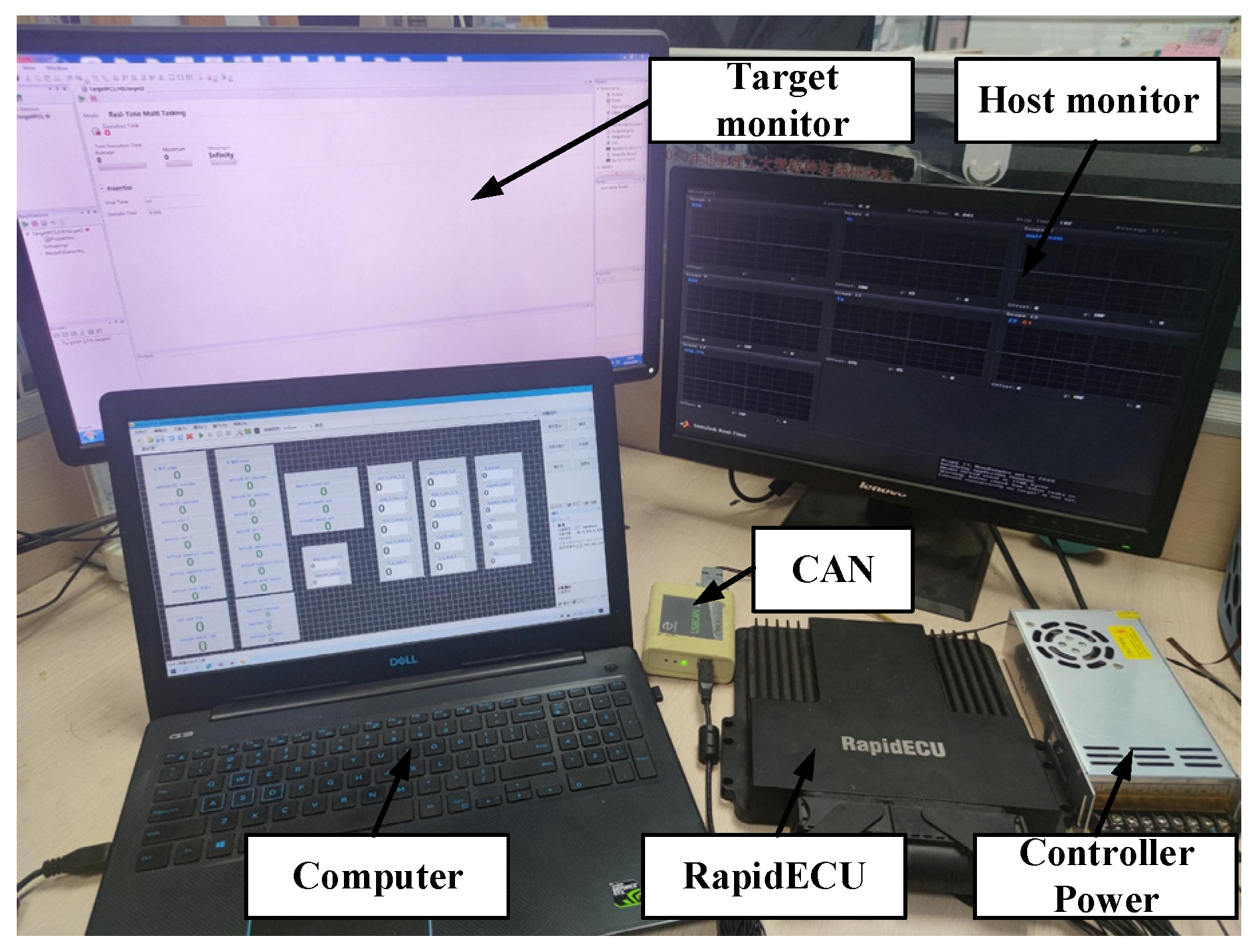
In order to validate the effectiveness of the proposed dual-loop control architecture and auxiliary loop torsional vibration optimization strategy, an HIL test bench was established, as illustrated in Figure 25. The experimental setup employs a RapidECU controller as the control unit, with the plant model being the Simulink-based driveline system developed in this study.
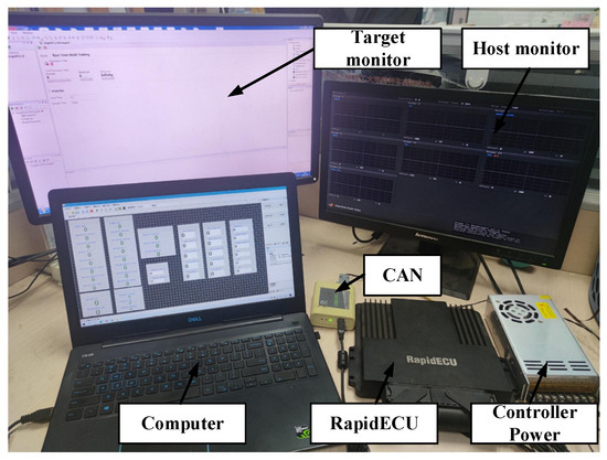
Figure 25.
HIL test platform.
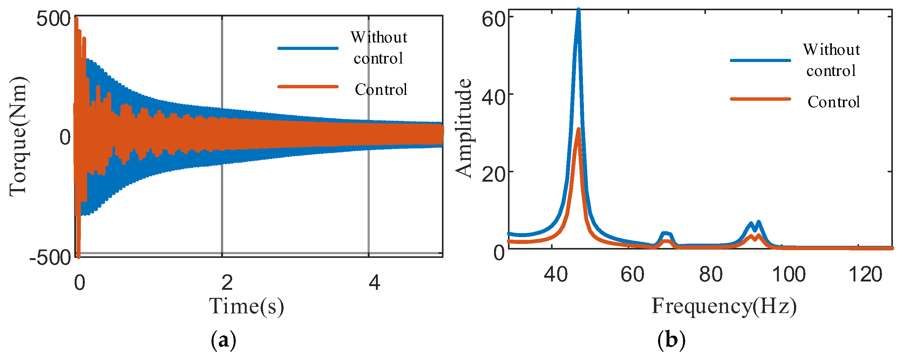
To validate the effectiveness of the proposed adaptive torsional vibration control strategy under steady-state conditions, simulations were conducted on the drivetrain operating in EVT2 mode with the engine speed fixed at 1400 rpm. The test protocol comprised two phases: (1) an initial 10 s baseline interval without active vibration suppression, during which significant torsional vibrations were observed at both the input and output shafts; and (2) a subsequent 20 s active control phase (initiated at t = 10 s) where the suppression torque was applied. For quantitative evaluation, the output shaft torque fluctuation was analyzed, with Figure 26 highlighting the transient response during the critical 9.5–11 s window to demonstrate the control algorithm’s rapid stabilization capability.
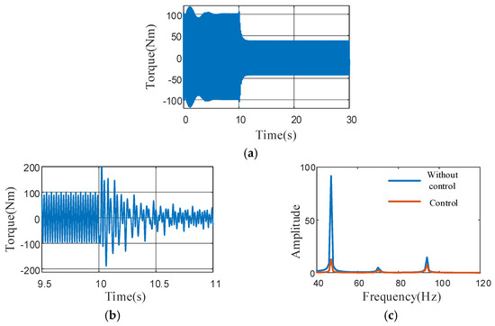
Figure 26.
Output shaft torque (1400 rpm). (a) Time-domain characteristics of output shaft torque (0–30 s), (b) time-domain characteristics of output shaft torque (9.5 s–11 s), (c) frequency-domain characteristics of output shaft torque.
As evidenced in Figure 26a, the output shaft torque oscillation amplitude demonstrates a 58% reduction from 100 Nm to 42 Nm under active control. The time-domain analysis further reveals that the proposed adaptive algorithm achieves rapid convergence within approximately 0.5 s, satisfying real-time control requirements. Frequency-domain results in Figure 26b indicate effective suppression of dominant harmonic components (primarily induced by engine torque fluctuations) in the driveline excitation spectrum.
Subsequently, the effectiveness of the control strategy was evaluated under both acceleration and deceleration conditions in EVT1 mode. The initial engine speed was set to 1200 rpm. During the simulation, the engine accelerated from 1200 rpm to 1800 rpm within the first 5 s, maintained this speed for 5 s, then decelerated back to 1200 rpm between 10–15 s. The simulation results are presented in Figure 27 and Figure 28.

Figure 27.
Engine acceleration characteristics under EVT1 mode. (a) Time-domain characteristics of output shaft torque, (b) frequency-domain characteristics of output shaft torque.
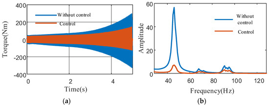
Figure 28.
Engine deceleration characteristics under EVT1 mode. (a) Time-domain characteristics of output shaft torque, (b) frequency-domain characteristics of output shaft torque.
The experimental results demonstrate that during engine acceleration and deceleration processes, the torsional vibration amplitude of the driveshaft is significantly attenuated after implementing the active vibration control strategy, with the adaptive filter achieving convergence within approximately 0.1 s. Time-domain analysis reveals a remarkable reduction in torque vibration response, along with effective suppression of amplitude at the excitation frequency points. From a frequency-domain perspective, due to the dynamic nature of the process where engine speed variations induce excitation frequency shifts, a substantial decrease in vibration amplitude is observed near resonance regions. These results confirm that the proposed adaptive torsional vibration control strategy maintains its effectiveness in suppressing vibrations under real-world operating conditions.
6. Conclusions
This paper presents a dual-loop active torsional vibration control framework and proposes a frequency-domain decoupling method for the dual-loop system. Two distinct active control strategies are employed to address torsional vibration challenges in HEV. For pure electric driving conditions, an ADRC-based torsional vibration suppression algorithm is introduced, which implements feedback control on the driveline. Simulation results demonstrate that the output shaft torque stabilizes within 0.7 s, representing a 70% reduction in settling time compared to the uncontrolled scenario. The ADRC algorithm effectively suppresses torsional vibrations during start–stop processes and outperforms PID control by delivering smoother torque transitions with superior vibration attenuation. For hybrid driving conditions, an RLS-based adaptive control algorithm is proposed. When the control intensity is maximized, the output shaft torque amplitude decreases from approximately 270 Nm to 75 Nm, achieving a maximum attenuation ratio of 72.2%. The effectiveness of these control algorithms is further validated through an HIL experimental platform, which confirms the adaptive algorithm’s rapid convergence and significant suppression of the dominant harmonic frequency components in the output shaft torque. However, due to current experimental limitations, this study did not incorporate a physical prototype of the driveline system. Practical applications may face challenges such as increased system disturbances and reduced modeling accuracy. Future work should focus on validating the proposed control algorithms, exploring advanced control strategies, and extending torsional vibration suppression to a broader range of HEV operating conditions.
Author Contributions
W.Z. and J.L. provided the conceptual idea of the article. X.L. and Z.H. helped with the organization and writing of the article. L.B. processed the data for the article. B.F. was responsible for the data analysis and interpretation of the article. M.J. helped with the data collection and research design. All authors have read and agreed to the published version of the manuscript.
Funding
This work was supported by the National Natural Science Foundation of China (52405071), Hunan Province Construction, Project (2023GK2088 & 2024JK2031 & 2024QY2009), Hunan Province Manufacturing Key Products (2023GXGG018), Postgraduate Scientific Research Innovation Project of Xiangtan University (XDCX2024Y240), and Doctoral Research Initiation Program, Xiangtan University (24QDZ34).
Data Availability Statement
The datasets generated and analyzed during the current study are available from the corresponding author on reasonable request.
Conflicts of Interest
The authors declare no conflicts of interest.
References
- Gauto, M.A.; Carazzolle, M.F.; Rodrigues, M.E.P.; de Abreu, R.S.; Pereira, T.C.; Pereira, G.A.G. Hybrid vigor: Why hybrids with sustainable biofuels are better than pure electric vehicles. Energy Sustain. Dev. 2023, 76, 101261. [Google Scholar] [CrossRef]
- Qin, Y.; Tang, X.; Jia, T.; Duan, Z.; Zhang, J.; Li, Y.; Zheng, L. Noise and vibration suppression in hybrid electric vehicles: State of the art and challenges. Renew. Sustain. Energy Rev. 2020, 124, 109782. [Google Scholar] [CrossRef]
- Cauet, S.; Coirault, P.; Njeh, M. Diesel engine torque ripple reduction through LPV control in hybrid electric vehicle powertrain: Experimental results. Control. Eng. Pract. 2013, 21, 1830–1840. [Google Scholar] [CrossRef]
- Tang, X.; Jin, Y.; Zhang, J.; Zou, L.; Yu, H. Torsional vibration and acoustic noise analysis of a compound planetary power-split hybrid electric vehicle. Proc. Inst. Mech. Eng. Part D J. Automob. Eng. 2014, 228, 94–103. [Google Scholar] [CrossRef]
- Zhu, X.; Liu, Z.; Shen, R.; Wang, Q.; Tang, A.; You, X.; Yu, W.; Wang, W.; Mao, L. Research on an Improved Carbon Emission Flow Model Considering Electric Vehicle Charging Fluctuation and Hybrid Power Transaction. Energies 2023, 16, 6835. [Google Scholar] [CrossRef]
- Aletras, N.; Broekaert, S.; Bitsanis, E.; Fontaras, G.; Samaras, Z.; Ntziachristos, L. Energy management algorithm based on average power demand prediction for plug-in hybrid electric trucks. Energy Convers. Manag. 2024, 299, 117785. [Google Scholar] [CrossRef]
- Song, D.; Wu, J.; Yang, D.; Chen, H.; Zeng, X. An active multiobjective real-time vibration control algorithm for parallel hybrid electric vehicle. Proc. Inst. Mech. Eng. Part D J. Automob. Eng. 2023, 237, 21–33. [Google Scholar] [CrossRef]
- Hall, C.M. The impact of hybridization, engine combustion method, and energy management system connectivity on heavy-duty vehicle operation. Proc. Inst. Mech. Eng. Part D J. Automob. Eng. 2021, 235, 2265–2280. [Google Scholar] [CrossRef]
- Wang, F.; Xia, J.; Zhu, X.; Xu, X.; Ni, Y.Q. An Online Predictive Energy Management Strategy for Multi-Mode Plug-in Hybrid Electric Vehicle With Mode Transition Schedule Optimization. IEEE/ASME Trans. Mechatron. 2024, 29, 1972–1984. [Google Scholar] [CrossRef]
- Liu, H.; Li, X.; Han, L.; Wang, W.; Xiang, C. Research on real-time control strategy of multi-power flow of dual-mode power-split hybrid electric vehicle. Proc. Inst. Mech. Eng. Part D J. Automob. Eng. 2022, 236, 2519–2543. [Google Scholar] [CrossRef]
- Zhang, X.M.; Yang, D.P.; Zeng, X.H.; Wu, Q.T.; Qian, Q.F.; Song, D.F. Data-Driven FMPC Based Dynamic Coordination Control Strategy for Power-Split Hybrid Electric Bus. IEEE Trans. Veh. Technol. 2023, 72, 9999–10012. [Google Scholar] [CrossRef]
- Liu, T.; Zeng, X.; Song, D. MPC-Based Coordinated Control of Gear Shifting Process for a Power-split Hybrid Electric Bus with a Clutchless AMT. Chin. J. Mech. Eng. 2022, 35, 144. [Google Scholar] [CrossRef]
- Han, L.; Zhou, X.; Yang, N. The Coordinated Control Strategy of Engine Starting Process in Power Split Hybrid Electric Vehicle Based on Load Observation. Electronics 2024, 13, 3373. [Google Scholar] [CrossRef]
- Xue, H.; Ballo, F.; Previati, G.; Gobbi, M. Eco-Driving of Electric Vehicles: Objective and Subjective Evaluation of Passenger Comfort by a Dynamic Driving Simulator. IEEE Trans. Veh. Technol. 2025, 74, 402–412. [Google Scholar] [CrossRef]
- Yan, D.; Lu, L.; Li, Z.; Feng, X.; Ouyang, M.; Jiang, F. Durability comparison of four different types of high-power batteries in HEV and their degradation mechanism analysis. Appl. Energy 2016, 179, 1123–1130. [Google Scholar] [CrossRef]
- Gao, P.; Xiang, C.; Liu, H.; Walker, P.; Zhang, N. Design of the frequency tuning scheme for a semi-active vibration absorber. Mech. Mach. Theory. 2019, 140, 641–653. [Google Scholar] [CrossRef]
- Chen, K.; Hu, J.; Peng, Z. Analysis of torsional stability and the dynamical characteristics of electromechanical systems. Adv. Mech. Eng. 2017, 9, 1–12. [Google Scholar] [CrossRef]
- Ning, D.; Sun, S.; Du, H.; Li, W.; Li, W. Control of a multiple-DOF vehicle seat suspension with roll and vertical vibration. J. Sound Vib. 2018, 435, 170–191. [Google Scholar] [CrossRef]
- Magliacano, D.; Viscardi, M.; Ciminello, M.; Dimino, I. Feasibility study for a tonal vibration control system of a mounting bracket for automotive gearboxes. Int. J. Mech. 2016, 10, 403–410. [Google Scholar]
- Elsisi, M.; Soliman, M.; Aboelela, M.A.S.; Mansour, W. ABC based design of PID controller for two area load frequency control with nonlinearities. TELKOMNIKA Indones. J. Electr. Eng. 2015, 16, 58–64. [Google Scholar] [CrossRef]
- Chen, S.; Hu, M. Active torsional vibration suppression of hybrid electric vehicle drive system based on optimal harmonic current instruction calculation method. Mech. Syst. Signal Process. 2023, 205, 110837. [Google Scholar] [CrossRef]
- Bouchard, M. New recursive-least-squares algorithms for nonlinear active control of sound and vibration using neural networks. IEEE Trans. Neural Netw. 2001, 12, 135–147. [Google Scholar] [CrossRef] [PubMed]
- Aslam, M.S.; Shi, P.; Lim, C.C. Robust Active Noise Control Design by Optimal Weighted Least Squares Approach. IEEE Trans. Circuits Syst. I Regul. Pap. 2019, 66, 3955–3967. [Google Scholar] [CrossRef]
- Jimenez-Gonzalez, J.; Gonzalez-Montañez, F.; Jimenez-Mondragon, V.M.; Liceaga-Castro, J.U.; Escarela-Perez, R.; Olivares-Galvan, J.C. Parameter Identification of BLDC Motor Using Electromechanical Tests and Recursive Least-Squares Algorithm: Experimental Validation. Actuators 2021, 10, 143. [Google Scholar] [CrossRef]
- Lamraoui, H.C.; Qidan, Z. Path following control of fully-actuated autonomous underwater vehicle in presence of fast-varying disturbances. Appl. Ocean Res. 2019, 86, 40–46. [Google Scholar] [CrossRef]
- Ahmed, N.; Humaidi, A.; Sabah, A. Clinical trajectory control for lower knee rehabilitation using ADRC method. J. Appl. Res. Technol. 2022, 20, 576–583. [Google Scholar] [CrossRef]
- Wu, Z.; Li, D.; Liu, Y.; Chen, Y. Performance Analysis of Improved ADRCs for a Class of High-Order Processes With Verification on Main Steam Pressure Control. IEEE Trans. Ind. Electron. 2023, 70, 6180–6190. [Google Scholar] [CrossRef]
- Zhou, Z.; Guo, R. A Disturbance-Observer-Based Feedforward-Feedback Control Strategy for Driveline Launch Oscillation of Hybrid Electric Vehicles Considering Nonlinear Backlash. IEEE Trans. Veh. Technol. 2022, 71, 3727–3736. [Google Scholar] [CrossRef]
- Wang, F.; Zhang, J.; Xu, X.; Cai, Y.; Ni, S.; Que, H. Torsional oscillation-considered mode transition coordinated control for a power-split PHEV based on action dependent heuristic dynamic programming. ISA Trans. 2021, 126, 597–616. [Google Scholar] [CrossRef]
- Zhang, X.; Liu, H.; Zhan, Z.; Wu, Y.; Zhang, W.; Taha, M.; Yan, P. Modelling and active damping of engine torque ripple in a power-split hybrid electric vehicle. Control. Eng. Pract. 2020, 104, 104634. [Google Scholar] [CrossRef]
- Liu, H.; Zhang, X.; Chen, Y.; Taha, M.; Xu, H. Active damping of driveline vibration in power-split hybrid vehicles based on model reference control. Control. Eng. Pract. 2019, 91, 104085. [Google Scholar] [CrossRef]
- Zhang, W.; Liu, H.; Zhang, X.; Wu, Y.; Gao, P.; Wang, Z.; Zhang, W. Torque ripple compensation control for hybrid UGVs in mode transition based on current harmonic control of a PMSM. Proc. Inst. Mech. Eng. Part D J. Automob. Eng. 2021, 235, 920–932. [Google Scholar] [CrossRef]
- Jinyu, Z.; Song, H.; Longyu, J.; Fuyuan, Y. Active Vibration Control Strategy for Online Application in a Range Extender. IEEE Access 2023, 11, 26686–26702. [Google Scholar] [CrossRef]
- Xie, Y.; Lim, K.; Liu, H.; Zhan, Z.; Ren, X.; Li, X.; Zhou, R.; Gao, P.; Xiang, C. Modelling of electromechanical coupling dynamics for high-speed EHT system used in HEV and characteristics analysis. Appl. Math. Model. 2024, 136, 115614. [Google Scholar] [CrossRef]
- Hu, J.; Wang, Z.; Liu, Y.; Liu, X.; Yang, X. Vibration characteristics of industrial robot joint servo transmission system based on electromechanical coupling. Meas. Sci. Technol. 2023, 34, 125147. [Google Scholar] [CrossRef]
- Ge, S.; Qiu, L.; Zhang, Z.; Wang, H.; Hu, M. Electromechanical coupling dynamic characteristics of electric drive system for electric vehicle. Nonlinear Dyn. 2024, 112, 6101–6136. [Google Scholar] [CrossRef]
- Urbaś, A.; Stadnicki, J. Applications of dynamics metamodels of an eccentric crank-slider mechanism in the initial phase of their design. Mech. Mach. Theory 2025, 205, 105886. [Google Scholar] [CrossRef]
- Yang, D.; Liu, H.; Gao, P.; Zhang, W.; Yan, Q.; Chen, K.; Yang, H. Research on Drive Torque Command Optimization and System Disturbance Rejection Mechanism for Torsional Vibration Control of Electro-Mechanical Transmission System. IEEE Trans. Transp. Electrif. 2025; early access. [Google Scholar]
- Zhang, W.; Liu, H.; Liu, J.G.; Yan, P.; Fu, B. Adaptive phase compensation method for primary harmonic disturbance in electromechanical composite transmission. J. Mech. Eng. 2024, 60, 354–365. [Google Scholar]


Disclaimer/Publisher’s Note: The statements, opinions and data contained in all publications are solely those of the individual author(s) and contributor(s) and not of MDPI and/or the editor(s). MDPI and/or the editor(s) disclaim responsibility for any injury to people or property resulting from any ideas, methods, instructions or products referred to in the content. |
© 2025 by the authors. Licensee MDPI, Basel, Switzerland. This article is an open access article distributed under the terms and conditions of the Creative Commons Attribution (CC BY) license (https://creativecommons.org/licenses/by/4.0/).