1. Introduction
The momentum wheel (MW), also known as a biased flywheel, is a key actuator in spacecraft attitude control systems. It enables satellites to maintain or adjust their orientation by generating control torque through high-speed rotation [
1,
2,
3,
4]. However, during operation, MWs often experience high-frequency jitter caused by structural imbalance, leading to micro-vibrations. These micro-vibrations are a major source of disturbance in high-resolution satellites, significantly degrading the pointing accuracy and stability of the attitude control system and ultimately reducing imaging quality [
5,
6].
A momentum wheel primarily consists of a shell assembly, a wheel body assembly, a bearing assembly, a motor, and commutation circuitry [
7,
8]. Among these, the wheel body assembly and bearing assembly are the key components responsible for providing control torque. Most momentum wheels in current use feature an assembled wheel body structure, where the spokes, rim, and hub of the wheel body are joined through welding and screw connections. However, when operating in harsh space environments over extended periods, this structure suffers from insufficient connection stiffness and poor stability. Additionally, it fails to eliminate the contact gap between the hub and the bearing sleeve, leading to axial and radial vibrations during operation, which contribute to micro-vibrations in the momentum wheel [
9].
To address these challenges, this paper proposes a novel integrated expandable wheel-body design for momentum wheels that eliminates welds and threaded joints to reduce assembly-induced deformation and enhance mechanical stiffness. The hub’s controlled elastic deformation enables high-precision bearing clamping, removing fit clearances and thus improving dynamic balance, vibration suppression, and resistance to mechanical shocks. The objectives of this work are to (1) develop a detailed structural design for the expandable wheel body, (2) evaluate its mechanical behavior through finite element simulations, and (3) validate its dynamic performance via random vibration tests at a rated speed of 5000 rpm under a 20–2000 Hz PSD profile to ensure an RMS acceleration below 70 g.
2. Wheel Assembly
There are two common structural types of wheel assemblies: assembled and integral. In an assembled wheel, the rim, spokes, and hub are made from different materials and assembled using welding, screws, or other connection methods. In contrast, an integral wheel is machined from a single piece of material, with the hub, spokes, and rim forming a unified structure. Compared to assembled wheels, integral wheels can effectively reduce deformation by eliminating the welding and threaded connections in traditional assembled momentum wheels; they also improve dynamic balance accuracy and are more suitable for the production of a single piece with enhanced resistance to impact and vibration.
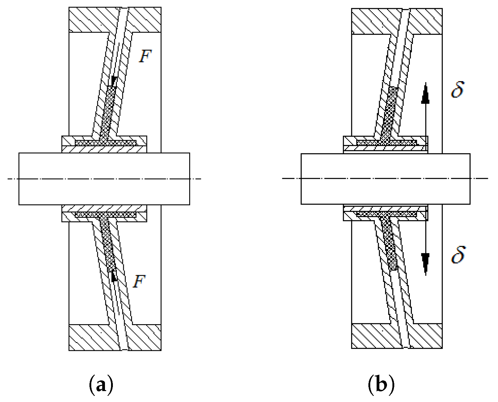
This paper proposes an improved momentum wheel assembly with an expandable structure for high-precision bearing clamping. This design eliminates clearance between the hub and shaft sleeve, enhancing rotational accuracy while ensuring easy assembly, disassembly, and high reliability. The expandable wheel assembly is shown in
Figure 1.
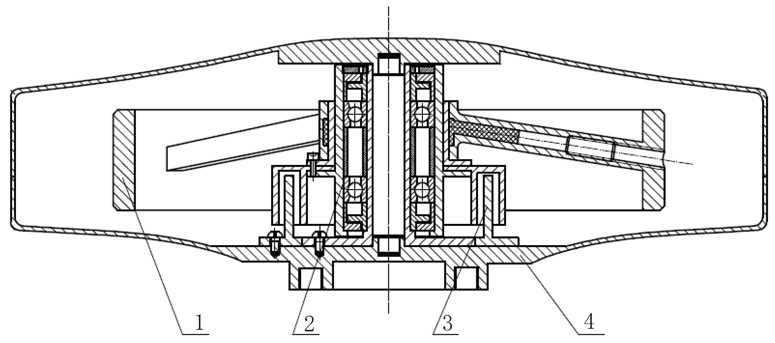
The expandable wheel assembly primarily consists of seven components: a rim, spokes, the outer ring of the hub, the inner ring of the hub, an elastomer, push rods, and preload screws. The rim, the spokes, and the outer ring of the hub, collectively referred to as the wheel body, are forged from 40CrNiMo quenched and tempered stainless steel blanks. After heat treatment, they are shaped through overall milling, during which the fan-shaped structure between the five spokes is removed. The hub’s inner ring is designed with seven through holes, of which five are used to connect it to the bearing assembly and the other two are for positioning. The end faces of the hub inner ring and the wheel body are welded together to prevent the elastomer from leaking. The spoke-type wheel body has five spokes, each inclined at an angle of 9°. To facilitate processing, the cross-section of each spoke is designed with an outer square and an inner circular hollow structure. Each spoke is sequentially installed with an elastomer, push rod, and preload screw. When the set screw is tightened, it pushes the push rod to move radially within the spoke cavity, causing the elastomer to flow. The thin-walled structure of the hub’s inner ring deforms elastically under pressure, achieving high-precision clamping of the bearing assembly, as shown in
Figure 2.
3. Bearing Assembly
Momentum wheels mostly use high-precision angular contact ball bearings for support. The bearing assembly consists of two angular contact ball bearings installed back to back. It is essential for the bearing assembly to have good lubrication performance to reduce friction and wear, ensuring the long lifespan and high stability of the momentum wheel. The structure of the bearing assembly is shown in
Figure 3.
4. Momentum Wheel
The motor and shell assembly are also essential components of the momentum wheel. Most existing momentum wheels utilize brushless DC motors, which feature a coreless stator design. These motors offer advantages such as long lifespan, high reliability, and low power consumption, fully meeting the technical requirements of satellite attitude control systems. The shell assembly is made of titanium alloy, which enhances the internal vacuum level of the momentum wheel while also satisfying the weight reduction requirements of aerospace applications.
The expandable wheel body, bearing assembly, motor, and shell are assembled to form the expandable momentum wheel designed in this study; an overall model of its design is illustrated in
Figure 4.
Figure 4 shows the main components of the expandable momentum wheel, including the expandable wheel body, bearing assembly, motor, and shell. During installation, the bearing assembly and motor rotor are first mounted onto the lower shell. The wheel body assembly is then installed onto the bearing sleeve, with the wheel hub secured using five screws. Subsequently, the radial positions of the five screws in the spokes are adjusted, applying pressure to the elastic bodies within the spokes. This pressure induces a slight elastic deformation in the inner hub ring, achieving high-precision clamping of the bearing assembly.
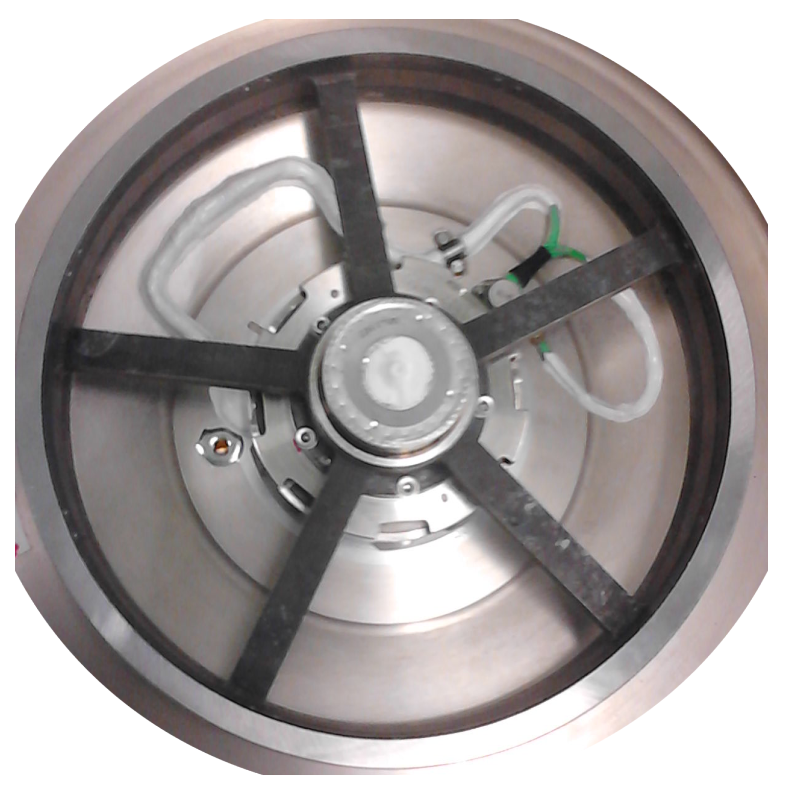
Additionally, the momentum wheel features an integral wheel body structure, which significantly enhances the strength of the wheel body and improves its resistance to impact and vibration in the complex dynamic environment of space. This design extends the operational lifespan of the momentum wheel and improves its overall performance in satellite attitude control applications. A physical diagram of the momentum wheel used in the subsequent tests is shown in
Figure 5.
5. Finite Element Analysis
During spacecraft launch, the momentum wheel undergoes sustained acceleration, leading to mechanical stress and dynamic loads. To ensure its structural integrity and reliable operation, a strength analysis is necessary to assess potential deformations, material fatigue, and stress concentrations.
5.1. Simplification of the Finite Element Model of Angular Contact Ball Bearings
For support, the wheel body assembly uses a set of back-to-back angular contact ball bearings (B7004), which need to be simplified. The dimensional parameters of the angular contact bearings are provided in
Table 1, with radial stiffness
and axial stiffness
[
10]. In ANSYS, two radial and one inclined spring-damping unit (COMBIN14) are used to replace each bearing ball, with a total of eight sets. The tilt angle
represents the bearing contact angle. The inner and outer rings of the bearing are retained. The simplified bearing model is shown in
Figure 6.
The following section calculates the stiffness of the radial and inclined COMBIN14 spring-damping units based on the radial and axial stiffness of the bearing. According to the stiffness equivalence principle and the bearing simplification schematic, we have
Solving these equations yields .
5.2. Finite Element Model of the Momentum Wheel
In this study, ANSYS is used to conduct the mechanical analysis of the momentum wheel in an environment of constant acceleration. The momentum wheel consists of the wheel body assembly, bearing assembly, motor, and shell assembly. If a finite element model were established based on the actual structure of the momentum wheel, computational efficiency would be significantly reduced. In practice, small features such as screw holes, chamfers, and fillets have minimal impact on the overall FEA results of the momentum wheel. Therefore, details on the wheel body, bearing assembly, motor, and shell have been simplified. SOLID186 is a higher-order solid element suitable for meshing curved surfaces, making it the chosen element type for this study. The momentum wheel is meshed using tetrahedral elements. The material properties of each component of the momentum wheel are listed in
Table 2. The finite element model of the expandable momentum wheel, comprising 264,328 nodes and 144,371 elements, is depicted in
Figure 7.
Table 2.
Material properties of each part of the momentum wheel.
Table 2.
Material properties of each part of the momentum wheel.
| Name | Material | Density (kg/m3) | Elastic Modulus (MPa) | Poisson’s Ratio | Yield Strength (MPa) |
|---|
| Wheel Body | 40CrNiMo [11] | 7.8 | 2.09 | 0.27 | 835 |
| Shell | Titanium Alloy | 4.45 | 1.14 | 0.34 | 668 |
| Spindle | 40Cr [12] | 7.8 | 2.06 | 0.29 | 785 |
| Bearing | 9Cr18Mo [13] | 7.7 | 2.22 | 0.3 | 696 |
| Other Parts | Steel | 7.8 | 2.10 | 0.3 | ≥600 |
5.3. Structural Strength Analysis
To verify the structural strength of the momentum wheel under high-speed rotation, an FEA was conducted by applying a rotational speed of 10,000 rpm, which is twice the rated speed of 5000 rpm, in order to account for potential overload conditions. In addition, inertial acceleration loads equivalent to 10G were applied to the momentum wheel separately in the x, y, and z directions to simulate extreme conditions encountered during the launch phase of the spacecraft.
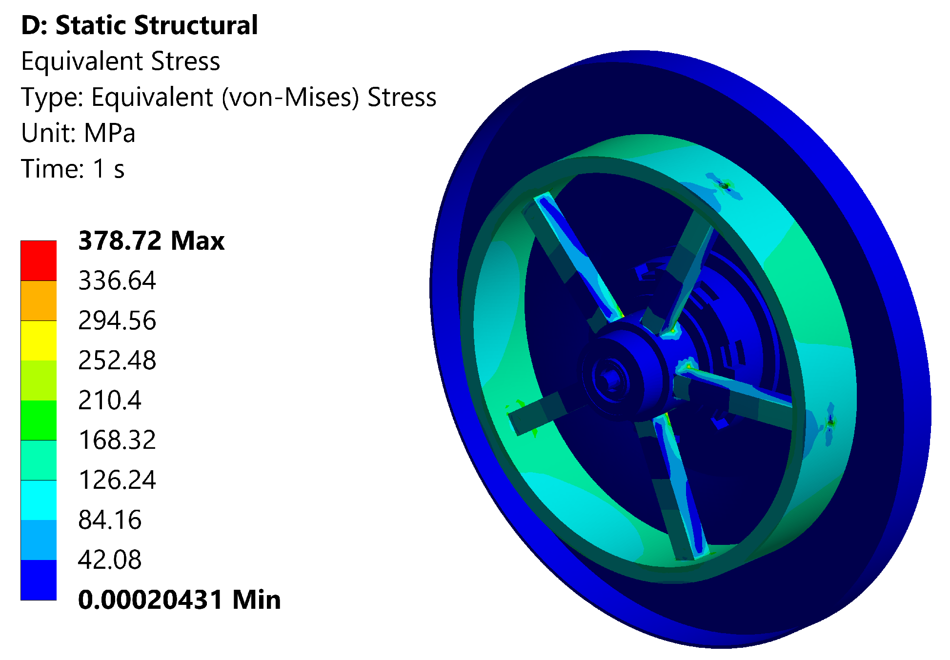
To reflect the actual installation constraints, a fixed boundary condition was applied to the bottom surface of the momentum wheel. The static structural system was used for the analysis. The simulation results for the von-Mises stress distribution under a rotational speed of 10,000 rpm are shown in
Figure 8. The maximum von-Mises stress, 378.72 MPa, occurs at the junction between the spokes and the hub of the wheel body. The yield strength of the wheel body material is 835 MPa. Clearly, the maximum stress is well below the yield limit, indicating that the structure meets the strength requirements. The momentum wheel can operate safely without fracture or failure both at the rated speed and under overspeed conditions.
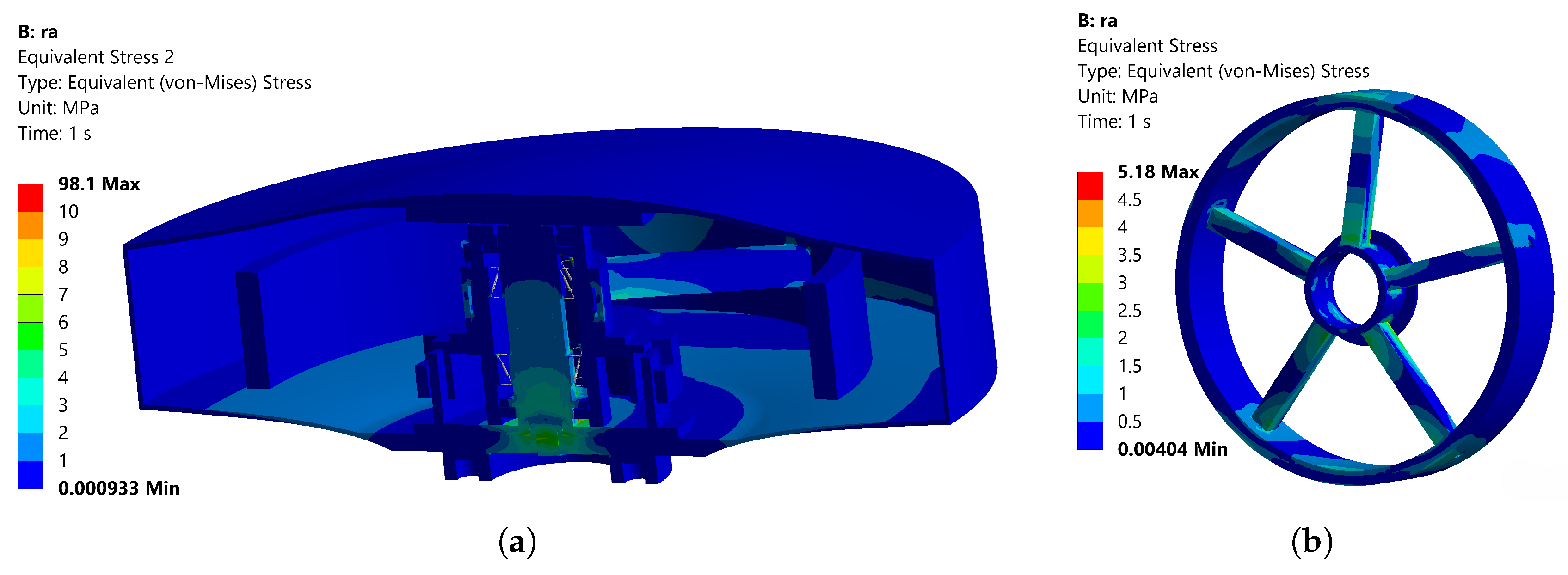
The simulation results for the von-Mises stress distribution at a radial acceleration of 10G are shown in
Figure 9. As shown in
Figure 9a, the maximum overall stress of 98.1 MPa occurs at the connection between the inner and outer races of the bearing and the COMBIN14 units, where the COMBIN14 elements are employed to replace the physical characteristics of the bearing. As shown in
Figure 9b, the maximum stress of 5.18 MPa in the wheel body assembly occurs at the connection between the spokes and the rim. The simulation results for the von-Mises stress distribution at a radial acceleration of 10G are shown in
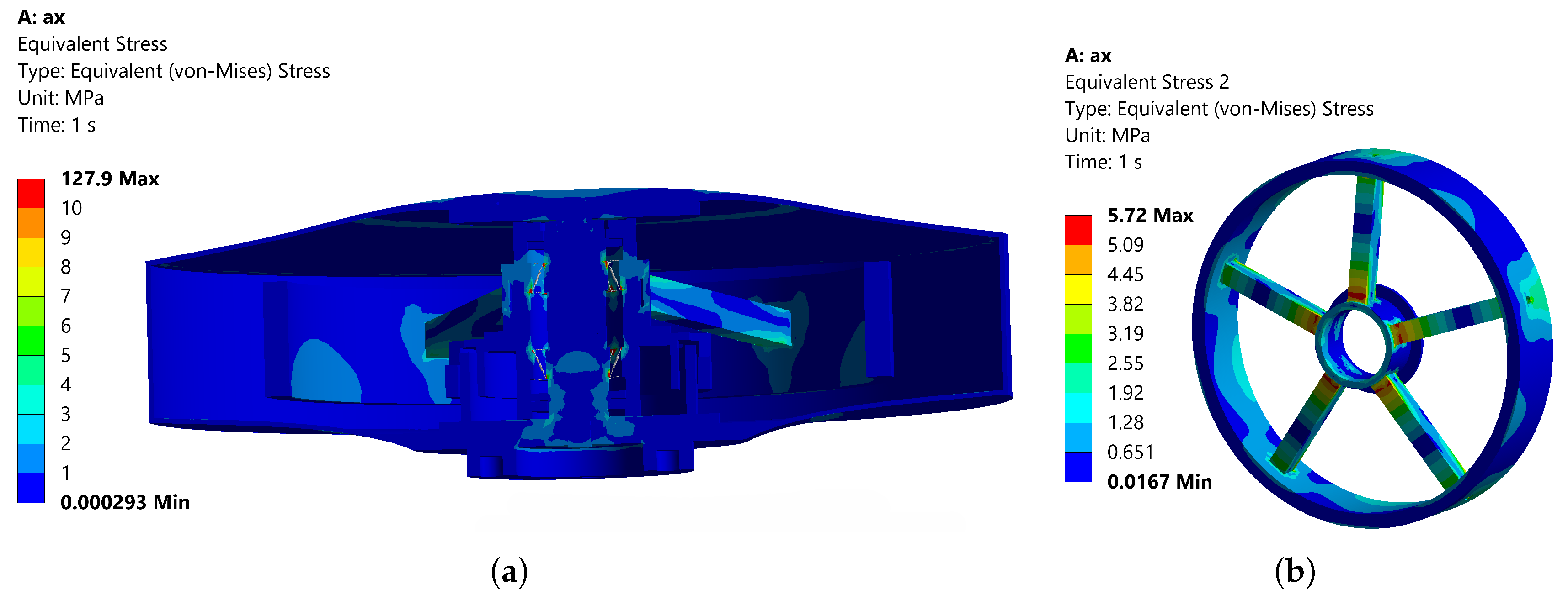
Figure 10. As shown in
Figure 10a, the maximum overall stress of 127.9 MPa occurs at the connection between the inner and outer races of the bearing and the COMBIN14 units. As shown in
Figure 10b, the maximum stress of 5.72 MPa in the wheel body assembly occurs at the connection between the spokes and the outer hub ring. Thus, the momentum wheel can operate safely and reliably in a constant-acceleration environment.
Additionally, a sensitivity analysis was conducted by varying the mesh density from coarse to fine. It was observed that the stress at the COMBIN14 elements increased with mesh refinement, primarily due to the enhanced resolution of local stress concentrations. Nevertheless, the average stress in the critical regions remained stable at ±3%, demonstrating that the simulation results are convergent and the finite element calculations are reliable.
5.4. Modal Analysis
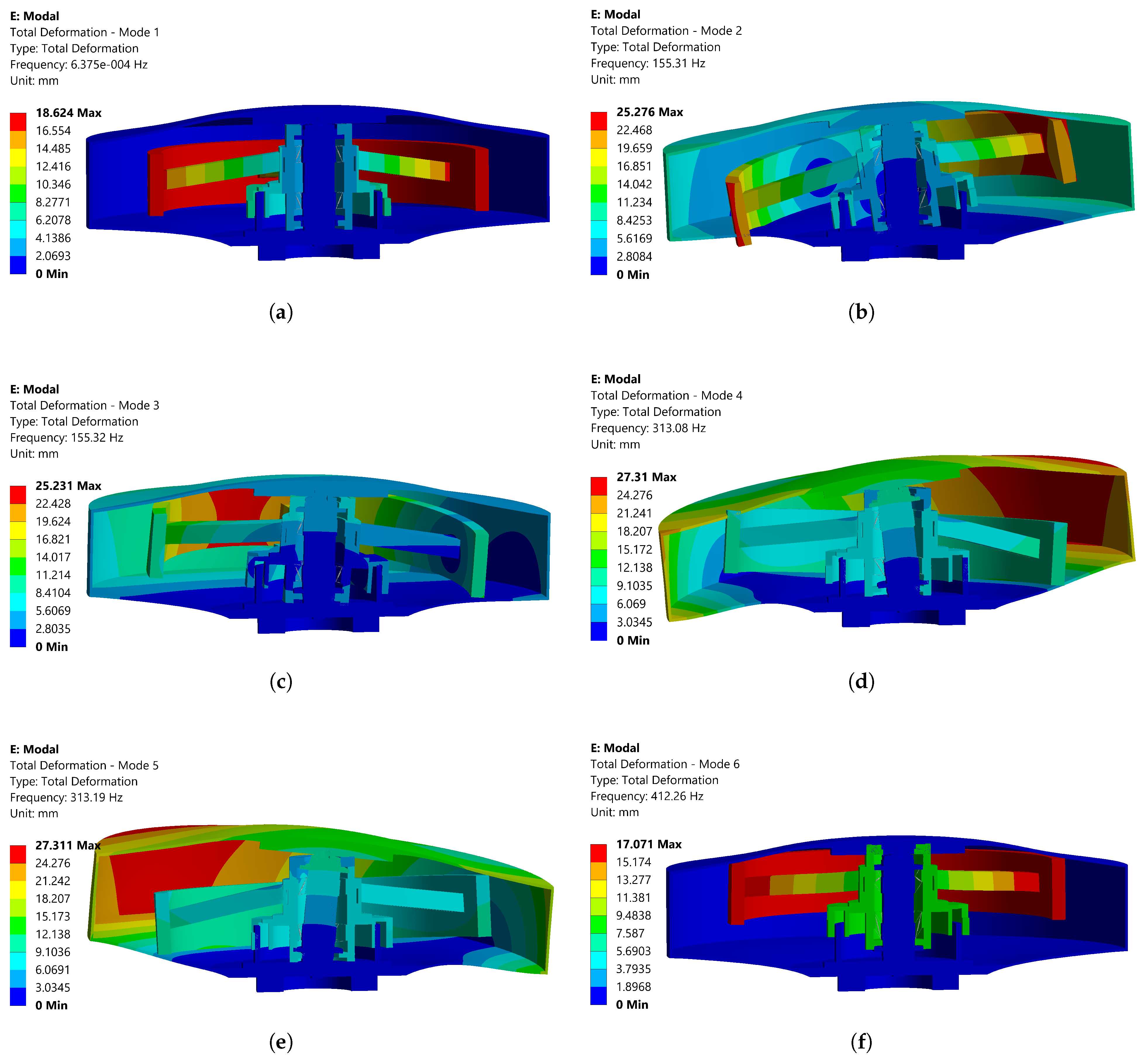
To further conduct dynamic response analysis, a constrained modal analysis was performed on the momentum wheel with the bottom surface fixed, simulating the actual installation condition. The first six natural frequencies are 0 Hz, 155.31 Hz, 155.32 Hz, 314.08 Hz, 314.19 Hz, and 413.26 Hz. The first natural frequency of the momentum wheel is 0 Hz, indicating the existence of a rotational degree of freedom due to the simplified modeling of angular contact bearings. The first nonzero natural frequency is 155.31 Hz, which meets the requirement of being higher than the rated rotational speed (83 Hz, 5000 rpm). It is also observed that the second and third natural frequencies are identical, as are the fourth and fifth natural frequencies, primarily due to the symmetric structure of the momentum wheel. The corresponding mode shapes are shown in
Figure 11.
The first mode shape corresponds to the rotation of the wheel assembly around the main axis; the second and third mode shapes correspond to the swinging of the wheel assembly in the and planes, respectively; the fourth and fifth mode shapes correspond to the swinging of the shell in the and planes; and the sixth mode shape corresponds to the rigid axial translation of the wheel assembly.
6. Random Vibration Response Analysis
Random vibration is a type of dynamic environment vibration, primarily originating from launch exhaust noise and aerodynamic noise during flight, with a frequency range of approximately 20–2000 Hz [
14,
15]. This vibration environment can dynamically propagate to the structural or instrumental levels of spacecraft, including system-level, subsystem-level, or component-level structures. It may cause structural damage, leading to performance degradation or even failure of instruments and equipment, posing significant threats to the safe operation of spacecraft [
16].
Therefore, this section conducts a random vibration test on the momentum wheel to verify its reliability in an environment with random vibration.
6.1. Analysis of Frequency Characteristics of Random Vibration
Let
be the random vibration excitation applied to the system in the time domain. According to Parseval’s theorem, it can be transformed into the frequency domain as follows:
where
is the random vibration excitation in the frequency domain.
By applying the Fourier transform to the autocorrelation function
, we obtain
where
is the power spectral density (PSD) function of the random vibration.
The inverse transform of this equation is
Equations (
3) and (
4) form a Fourier transform pair, which is known as the Wiener–Khinchin theorem.
For Equation (
4), if we set
, then
It is known that the autocorrelation function satisfies
where
is the mean square value of the random vibration, which represents the total energy of the random vibration.
From Equations (
5) and (
6), we obtain
From the above equations, the PSD function
represents the distribution of the mean square value of the random vibration in the frequency domain. In other words, the PSD function
indicates the energy distribution across frequencies [
17].
6.2. Statistical Characteristics of Random Vibration Response
The response of a linear system under any excitation can be obtained using the convolution integral:
Extending the integration limits of Equation (
8) to
and
does not affect the result, yielding
Let be the random vibration excitation applied to the system, and let be its response.
The autocorrelation function of the random vibration response is given by
After calculation, the PSD of the random vibration response is
where
is the PSD of the random vibration excitation, while
is the system’s frequency response function.
The mean square value of the response is
From Equation (
12), it is evident that, given the PSD of the random vibration excitation and the system’s frequency response function, the random vibration response of the system can be determined.
When the system is subjected to multiple independent and uncorrelated random vibration excitations, the total response PSD
is the sum of the power spectral densities of all the excitation responses:
Equation (
13) indicates that the system’s random vibration response depends not only on external excitations but also on the system’s inherent characteristics. In random vibration response analysis, studying the relationship between applied random vibration excitation and the system’s response can reveal structural characteristics and assess the reliability of the structure [
18].
6.3. Random Vibration Experiment
To verify the reliability of the expandable momentum wheel and assess its ability to withstand environments of vibration, a random vibration test was conducted using specialized equipment to simulate the vibration environment of space. Prior to the experiment, a dynamic balancing test was performed on the momentum wheel, achieving a static imbalance of 122 mg·cm and a dynamic imbalance of 693 mg·cm². The wheel was then sealed and subjected to a vacuum treatment.
The momentum wheel was mounted onto the vibration table using bolts. The acceleration was measured at two points: measurement point A1 was placed at the crown top of the shell, and measurement point A2 was located on the welded band of the shell side. Additionally, a control point was placed on the base of the momentum wheel to provide feedback on the vibration conditions applied by the vibration table. A schematic diagram is shown in
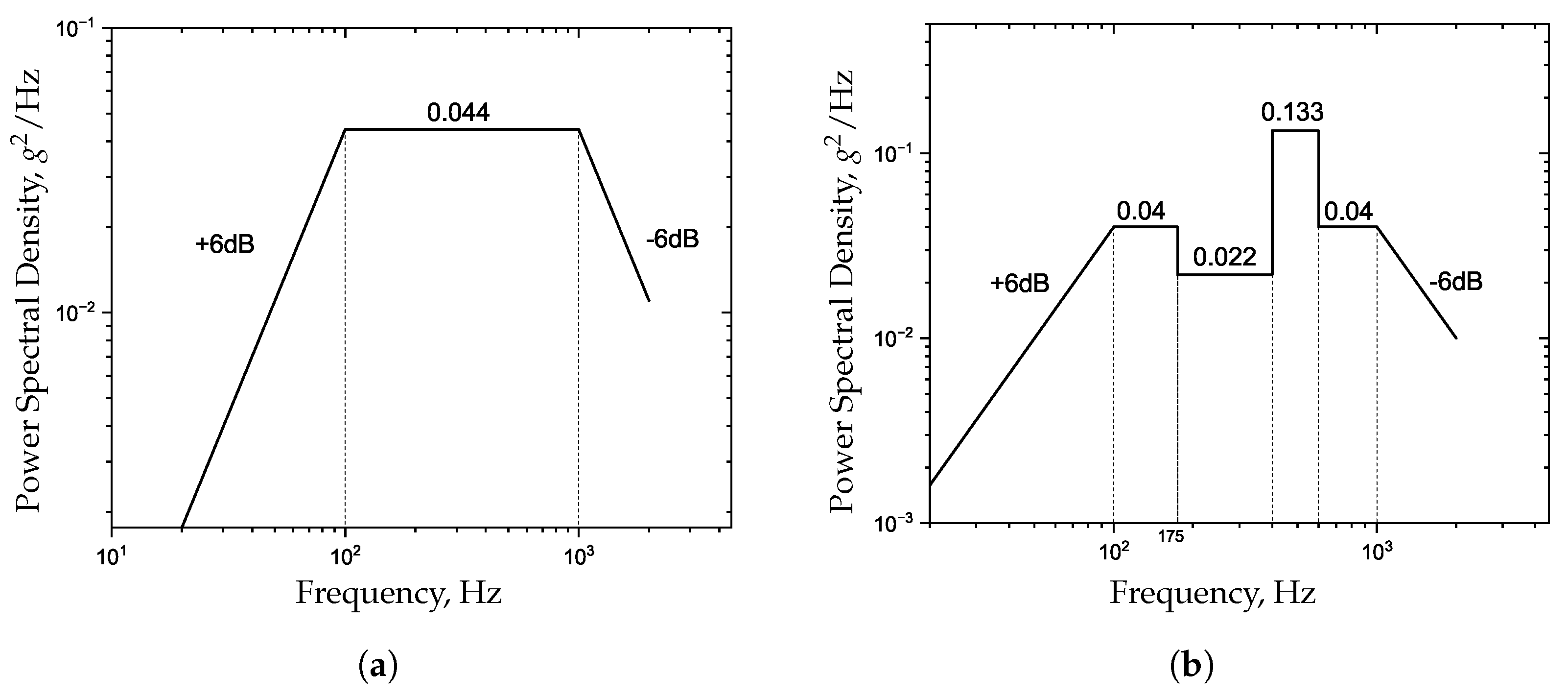
Figure 12. According to the design requirements, the acceleration PSD curves for random vibration in the x, y, and z directions are depicted in
Figure 13, with a sweep duration of 1 min.
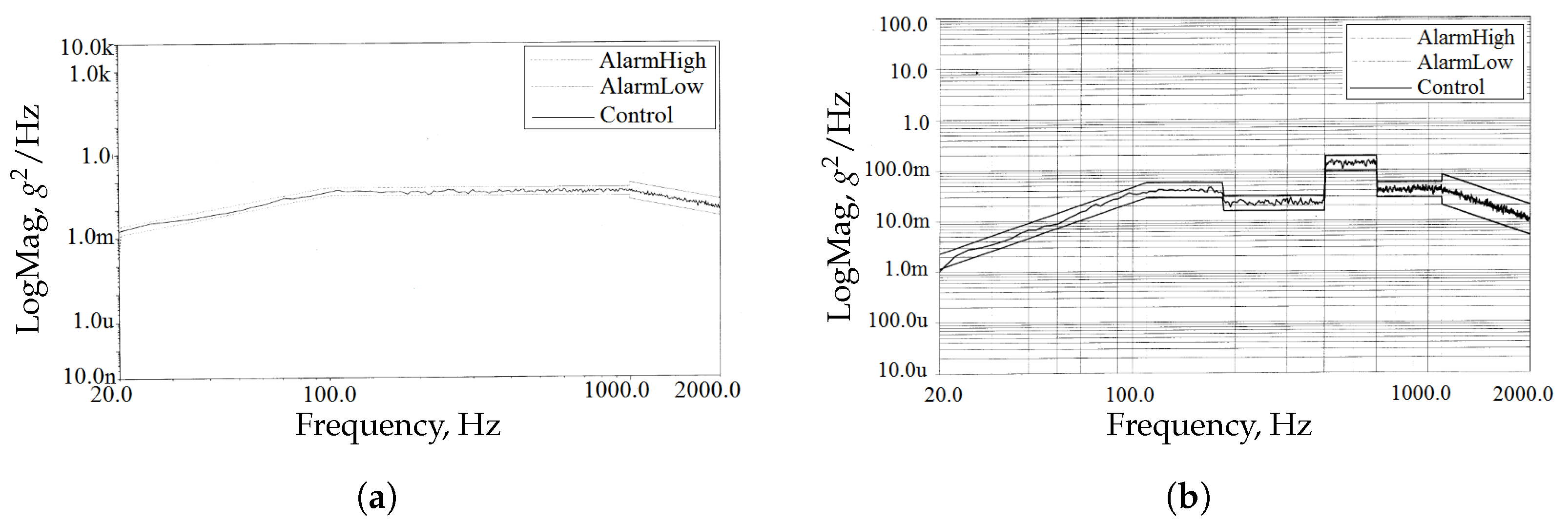
The control spectral curves for the random vibration test are shown in
Figure 14, where the AlarmHigh curve represents the upper tolerance band, the AlarmLow curve represents the lower tolerance band, and the Control curve is the actual control spectral curve. The region between the AlarmLow and AlarmHigh curves defines the allowable error range. Since the acceleration PSD curves for the x and y directions at the control point are identical, the y-direction control spectral curve is omitted. As observed in
Figure 14, the control spectral curves for the x and z directions fall within the tolerance band, indicating that the applied test conditions are within the allowable error range.
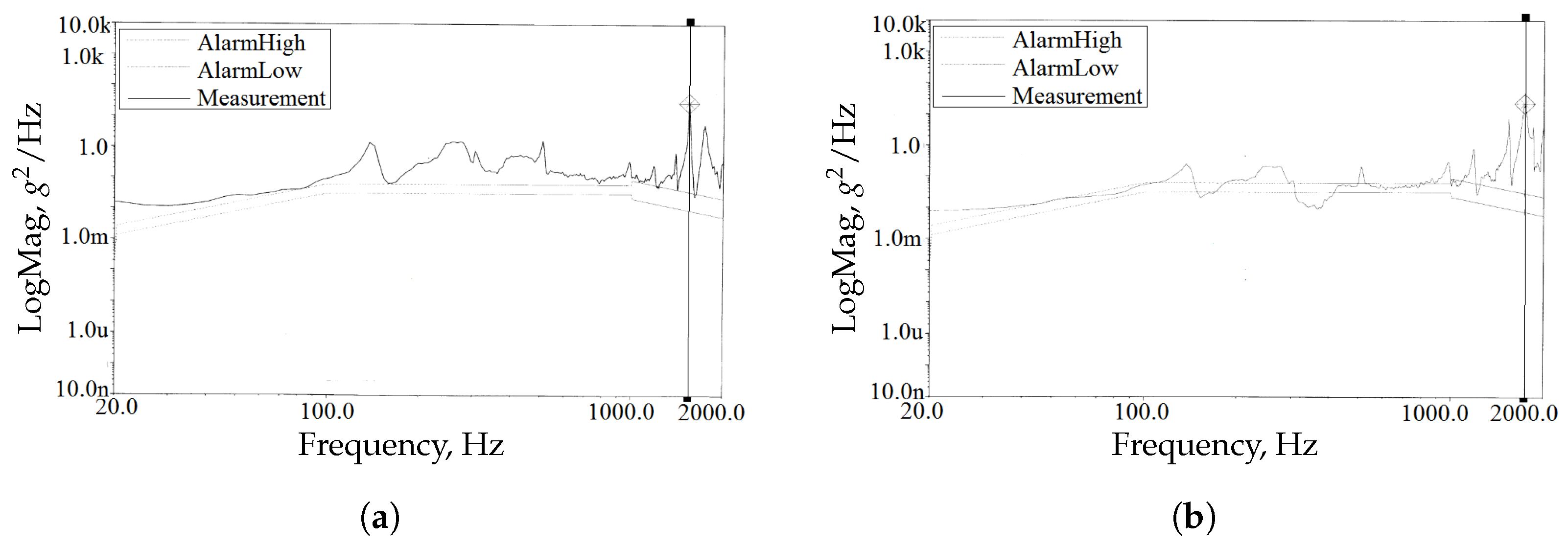
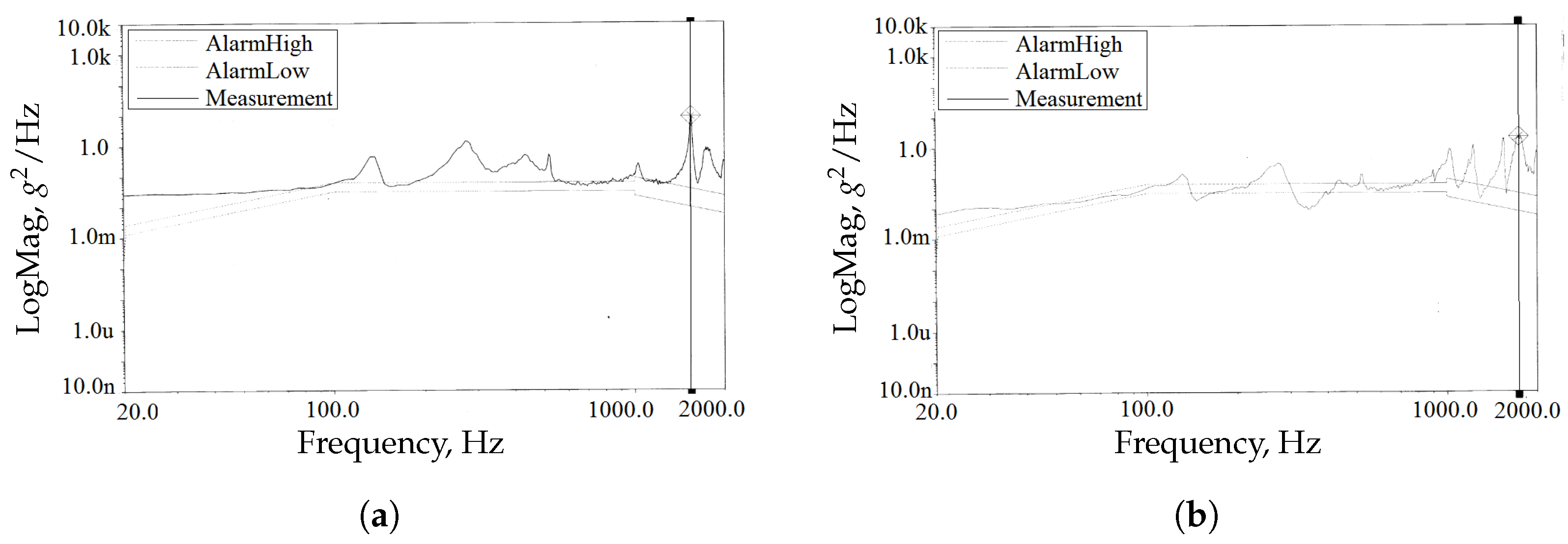
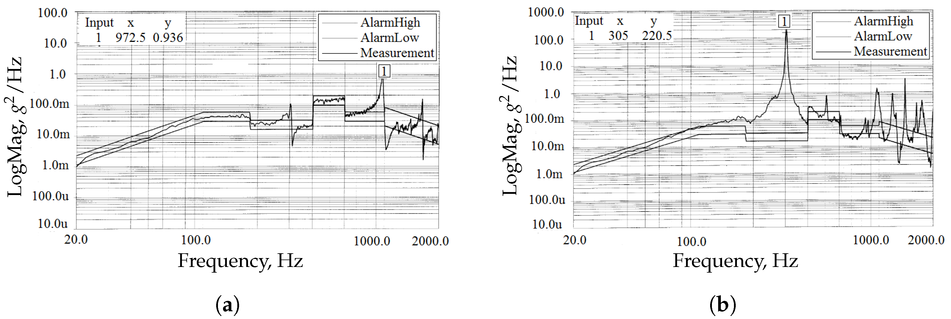
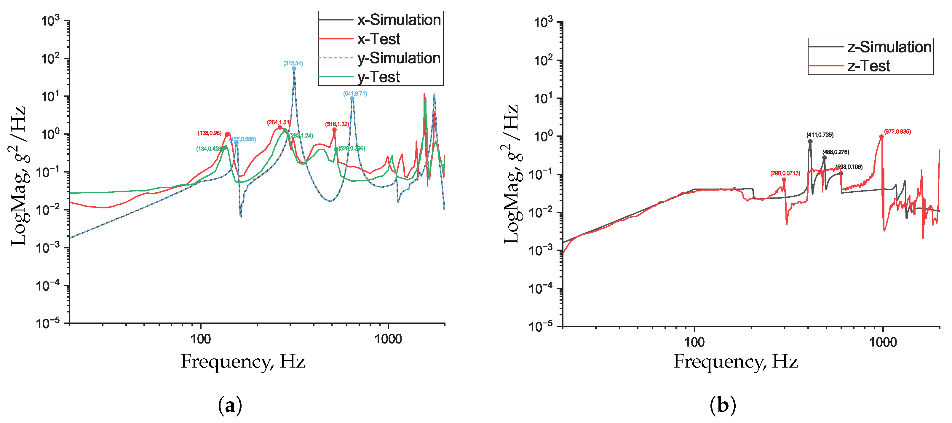
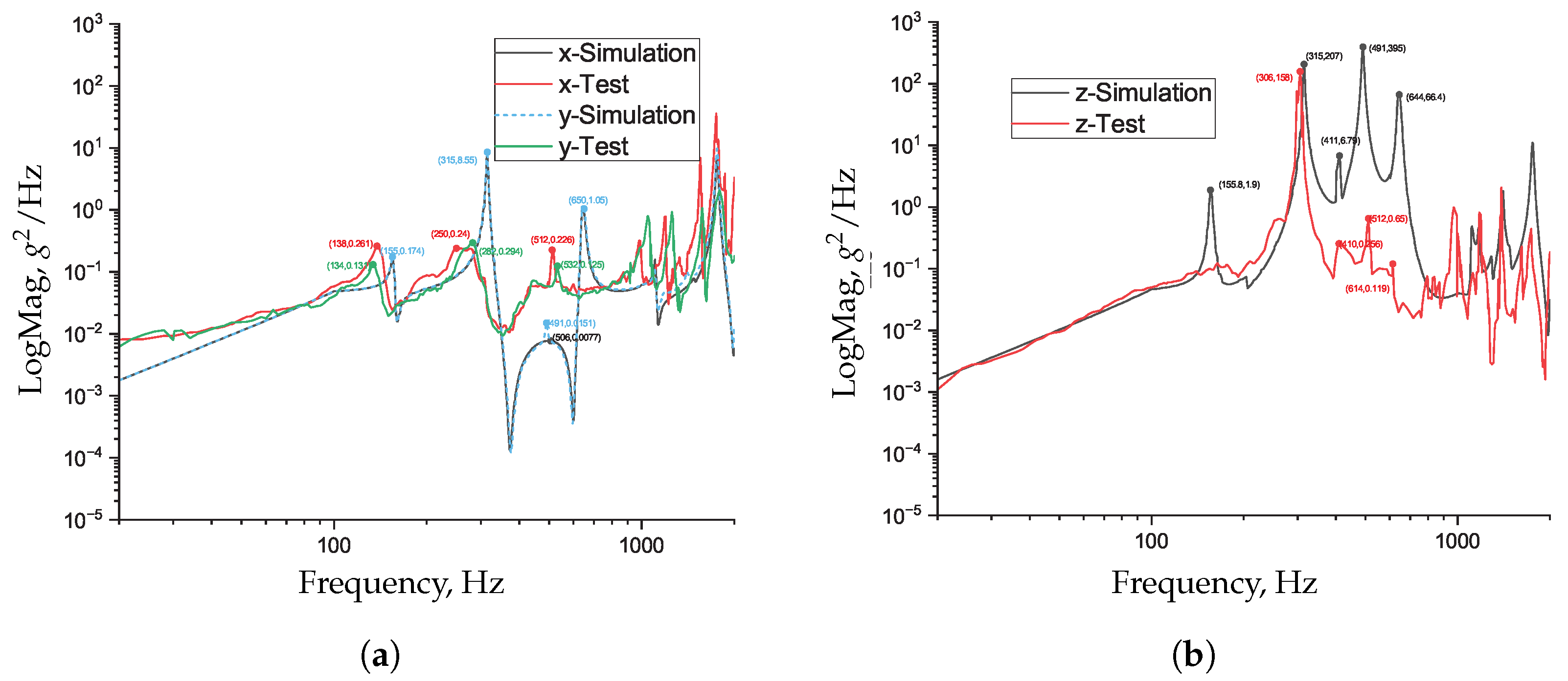
The raw response spectral data at measurement points A1 and A2 in the x, y, and z directions are shown in
Figure A1,
Figure A2, and
Figure A3, respectively. For comparative reference, these data are re-plotted in
Figure 15 and
Figure 16, where each curve labeled with -Test represents the result of random vibration testing.
The maximum and total root mean square (RMS) acceleration responses at each measurement point were statistically evaluated using the raw acceleration data, as summarized in
Table 3.
From
Table 3, it can be seen that under x-direction excitation, the maximum response accelerations at measurement points A1 and A2 are significantly greater than those under y- and z-direction excitation. However, under z-direction excitation at 305 Hz, the response acceleration at measurement point A2 reaches 220 g²/Hz. Furthermore, the total RMS response under x-direction excitation is also considerably higher than in the other two directions, with the highest total RMS response of approximately 41.53 g occurring at A2. According to the space dynamic environment specifications provided by the project, the RMS acceleration response required for the reliable operation of the momentum wheel is 70 g. The analysis results demonstrate that the momentum wheel satisfies this requirement, indicating that it meets the random vibration response criteria for space applications.
Following the vibration test, the expandable momentum wheel was disassembled for inspection. No fractures, permanent deformations, or other forms of damage were observed in critical components—including the wheel body, main shaft, bearings, and bushings—further confirming that the expandable momentum wheel meets both the strength and reliability requirements.
6.4. Random Vibration Simulation
To validate the accuracy and dynamic fidelity of the finite element model, a random vibration FEA was performed based on the preceding modal analysis (
Section 5.4) and the specified PSD inputs (
Figure 13), which were applied to the fixed support located at the bottom surface of the momentum wheel. The results are also plotted in
Figure 15 and
Figure 16, where each curve labeled with -Simulation represents the numerical response predicted by the FEA.
The simulation results exhibit a similar overall trend to the experimental data. While noticeable differences can be observed in the amplitude of the peak responses, the corresponding peak frequencies remain closely aligned between the test and the simulation. Particular attention is given to the first nine modes under 700 Hz; their peak frequencies and mode shapes are summarized in
Table 4.
As shown in
Figure 15 and
Figure 16 and
Table 4, the resonant frequencies obtained from the test are generally lower than those predicted by the simulation. This may be partially attributed to the absence of damping modeling in the finite element analysis (FEA), although damping primarily affects response amplitudes rather than frequency positions. The higher peak amplitudes in the simulation are also consistent with the lack of damping.
In the x and y directions, the test frequencies are, on average, 16 ± 5% lower than the simulated natural frequencies, indicating reasonably good correlation. Furthermore, the z-direction response at measurement point A2 shows that the simulated and measured frequencies are closely matched, which suggests that the axial damping is relatively small. This observation is consistent with the physical characteristics of the system: the momentum wheel mainly rotates about its axis, resulting in significant radial loads due to centrifugal forces and bearing friction. These loads lead to higher radial damping. In contrast, the axial direction typically allows a small amount of clearance in the bearing design, resulting in lower contact pressure and lesser damping, as the axial load is mainly supported by the thrust-bearing components.
Nevertheless, at certain locations, discrepancies between the simulation and experimental peak frequencies are observed. These are likely caused by simplifications in the geometric model—such as the omission of motors or other components—and the idealized modeling of joint stiffness or preload. In practice, effects such as local looseness, contact nonlinearity, or coupling with unmodeled components can lead to additional localized vibration modes not captured in the simulation.
Overall, the frequency positions and distribution trends observed in the random vibration test are largely consistent with the simulation results, validating the rationality of the model’s stiffness and mass distribution. Although some discrepancies in amplitude response remain, they are most likely due to uncertainties in damping parameters and simplifications of local structural details.
7. Conclusions
A novel expandable momentum wheel was independently designed, utilizing the elastic deformation of the hub to achieve high-precision clamping of the bearing sleeve. This design effectively reduces the vibratory force generated during rotation, thereby enhancing the stability of the momentum wheel in the dynamic environment of space while improving its impact resistance and overall reliability. Based on the stiffness equivalence principle, a finite element model of the momentum wheel was established by simplifying the finite element model of the angular contact ball bearing, and its static mechanical response at an overloaded rotational speed of 10,000 rpm under a constant acceleration of 10G was analyzed. The results indicate that the designed momentum wheel satisfies the strength requirements of the launch process, with a maximum von-Mises stress of 378.5MPa. Furthermore, a random vibration finite element analysis was conducted by applying a reasonable acceleration power spectral density to simulate the random vibration environment of space. A random vibration test was first conducted, and the acceleration response spectra at two measurement points were obtained. Finite element analysis (FEA) was subsequently performed for comparison. The results showed a consistent trend between the test and FEA in the low-frequency range, with the peak frequencies in the x and y directions differing by 16% ± 5% between the experimental and simulated results, thereby validating the effectiveness of the FEA model. Furthermore, the analysis confirmed that the designed momentum wheel meets the strength requirements to withstand the random vibration conditions found on spacecraft.

