
The Engineering Design and Prototyping of an Auxiliary Standing Toilet Chair Driven by Electric Cylinders


Abstract
1. Introduction
- Existing products and patents typically feature seat links with limited rotation around the knee joint, generally ranging from 16° to 30°, which falls short of the required 45° gravity transfer angle.
- The rotation angle of the seat must be increased while ensuring the seat height aligns with the standing position to eliminate tiptoeing hazards.
- The actuator force required for a 150 kg user to stand in commercially available products ranges from 1700 to 6070 N.
- Most auxiliary standing toilet chair mechanisms incorporate four-bar linkage mechanisms.
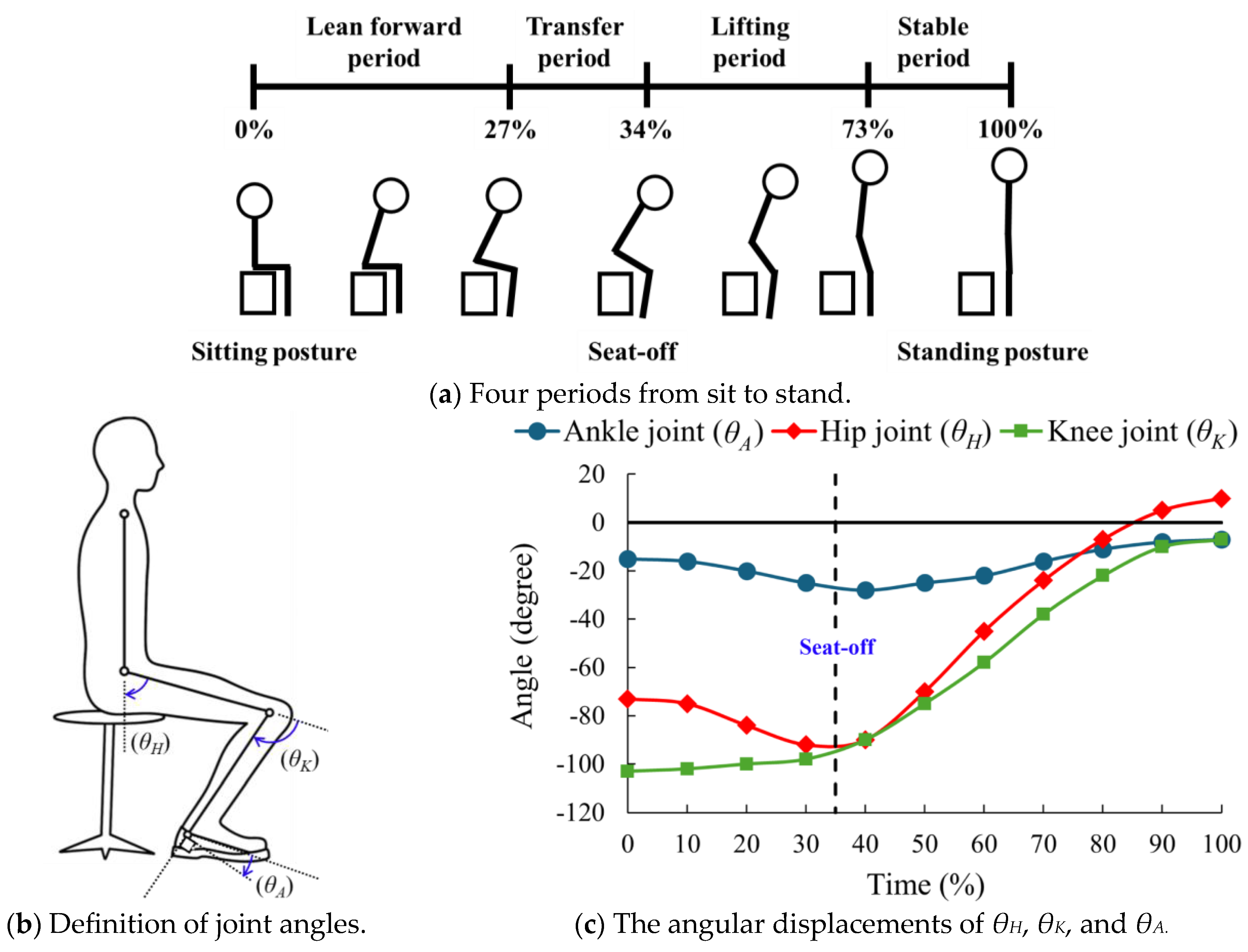
2. Sit-to-Stand
3. Existing Mechanism
3.1. Toilet Aid for Older People [3]
- The overall height is too high, and the feet cannot be completely placed on the ground.
- The stroke of the actuator is too large (250 mm).
- The rotation angle of the seat link is only 16°, which does not meet the movement requirements of the human body during the transition from sitting to standing.
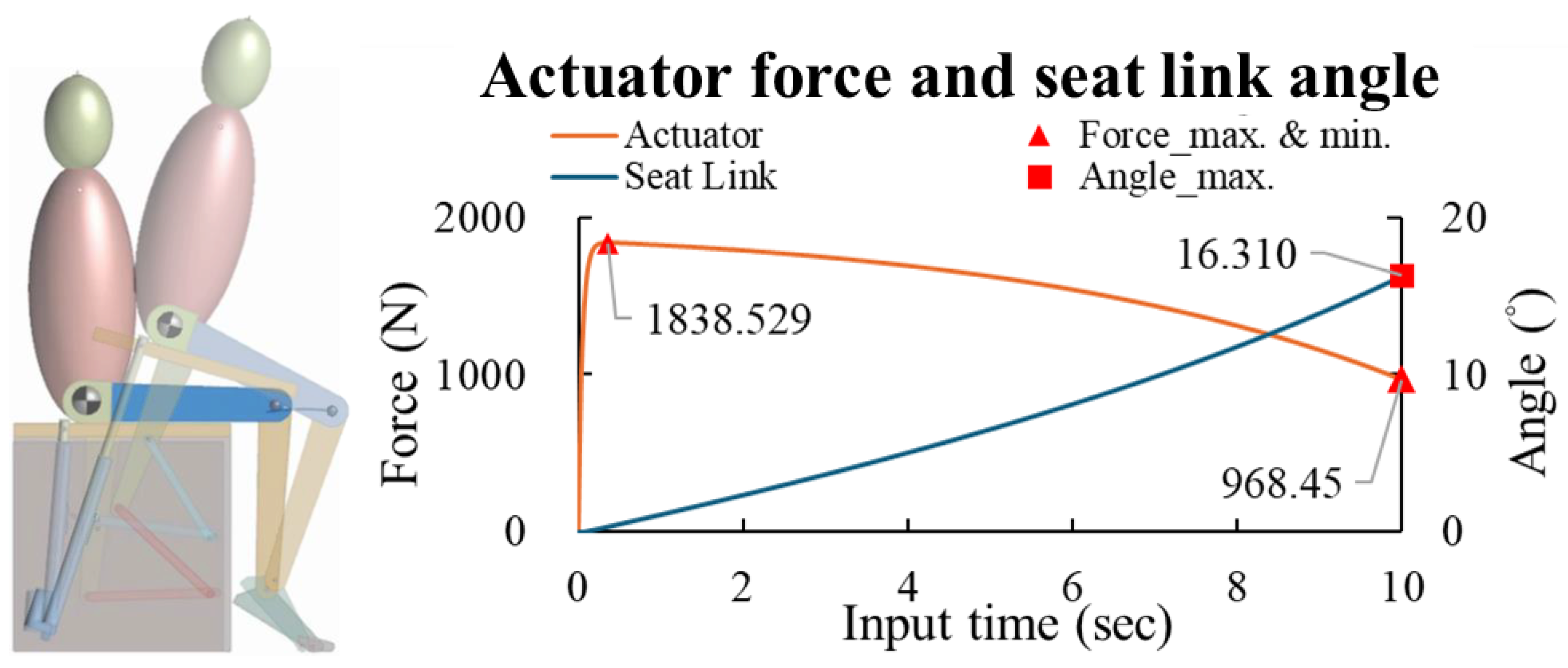
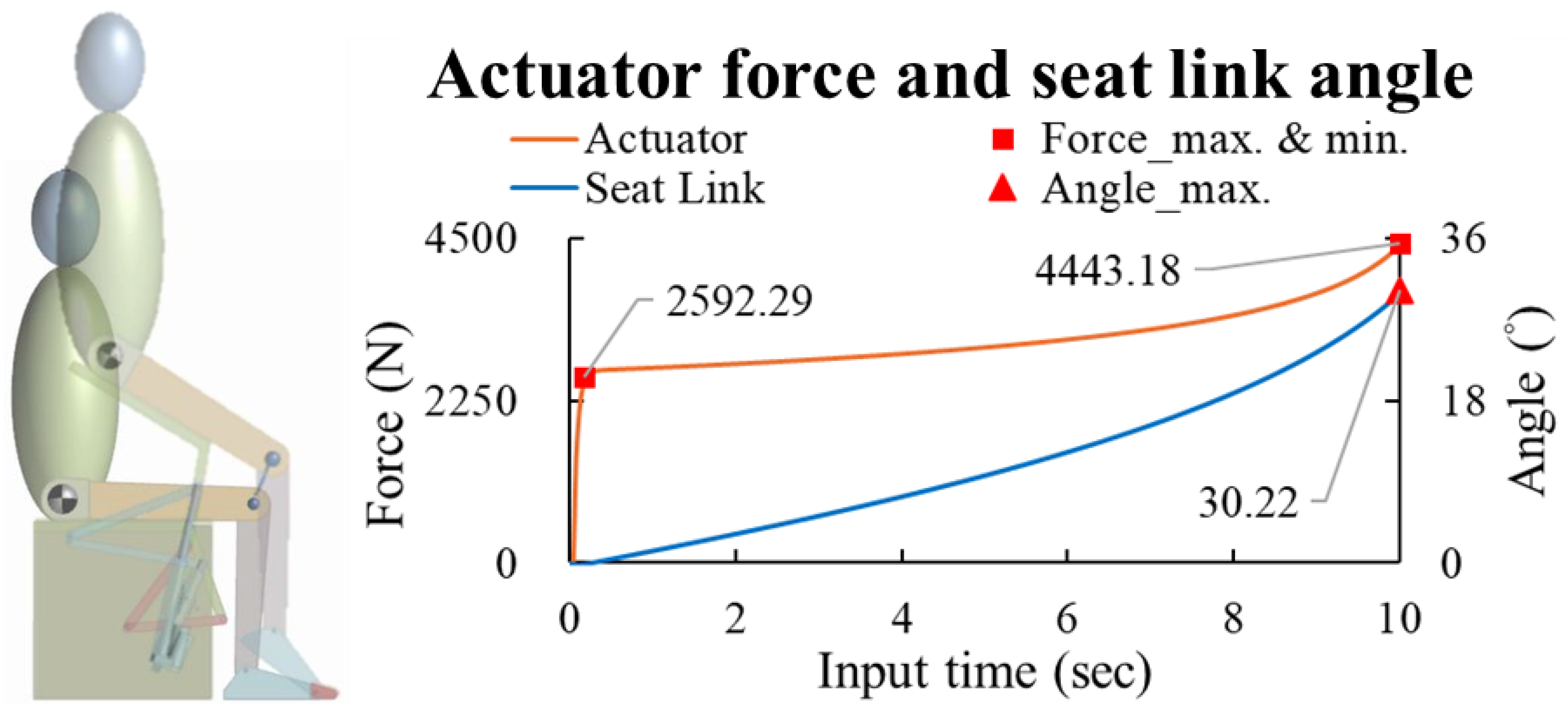
3.2. Lifting Mechanism for Toilets [4]
- The seat link is raised too high, and users must stand on their tiptoes, which increases the risk of injury.
- The rotation angle of the seat link is only 30.22°, which does not meet the movement requirements of the human body during the transition from sitting to standing.
- The positioning of the actuator is suboptimal, requiring a high actuator force of 4443 N.
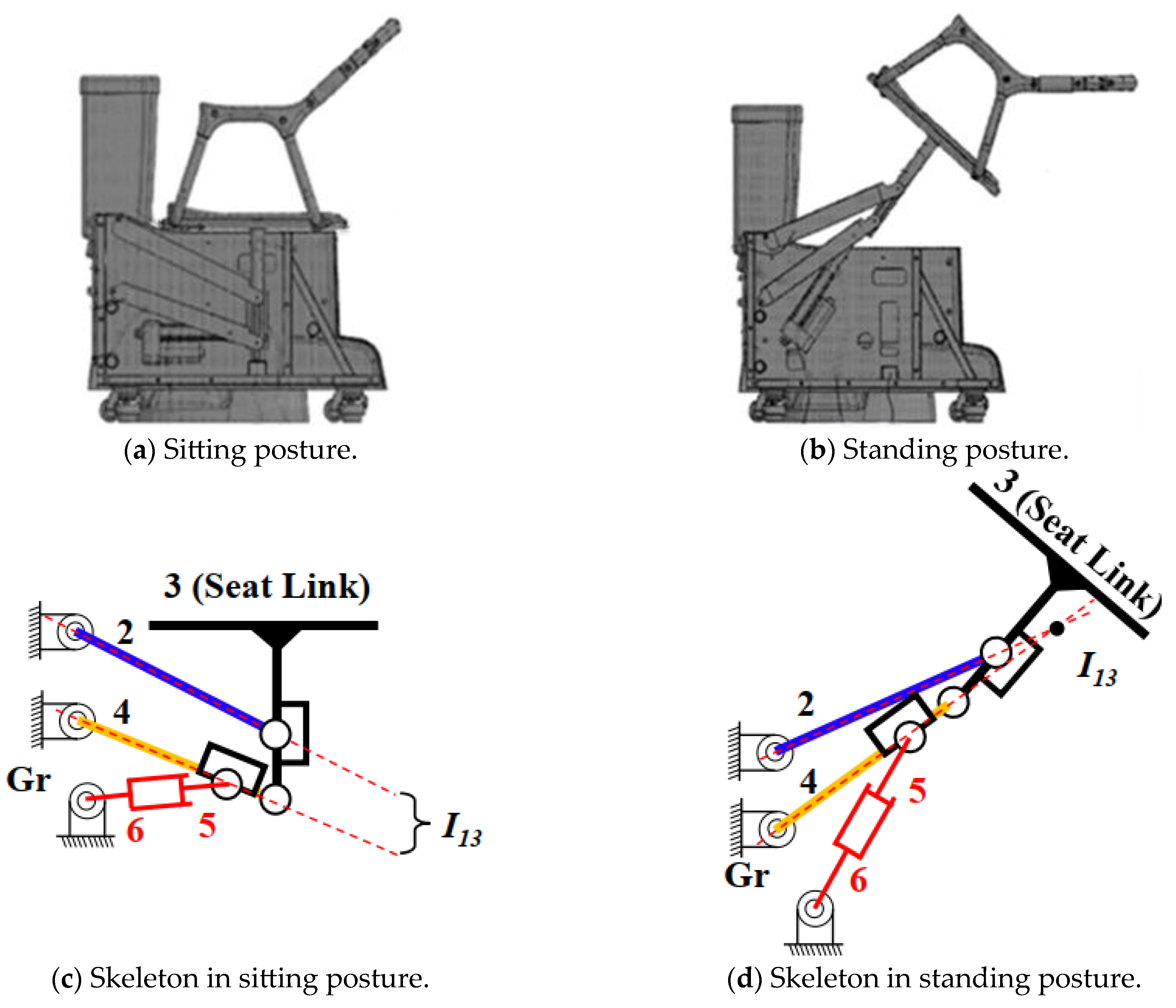
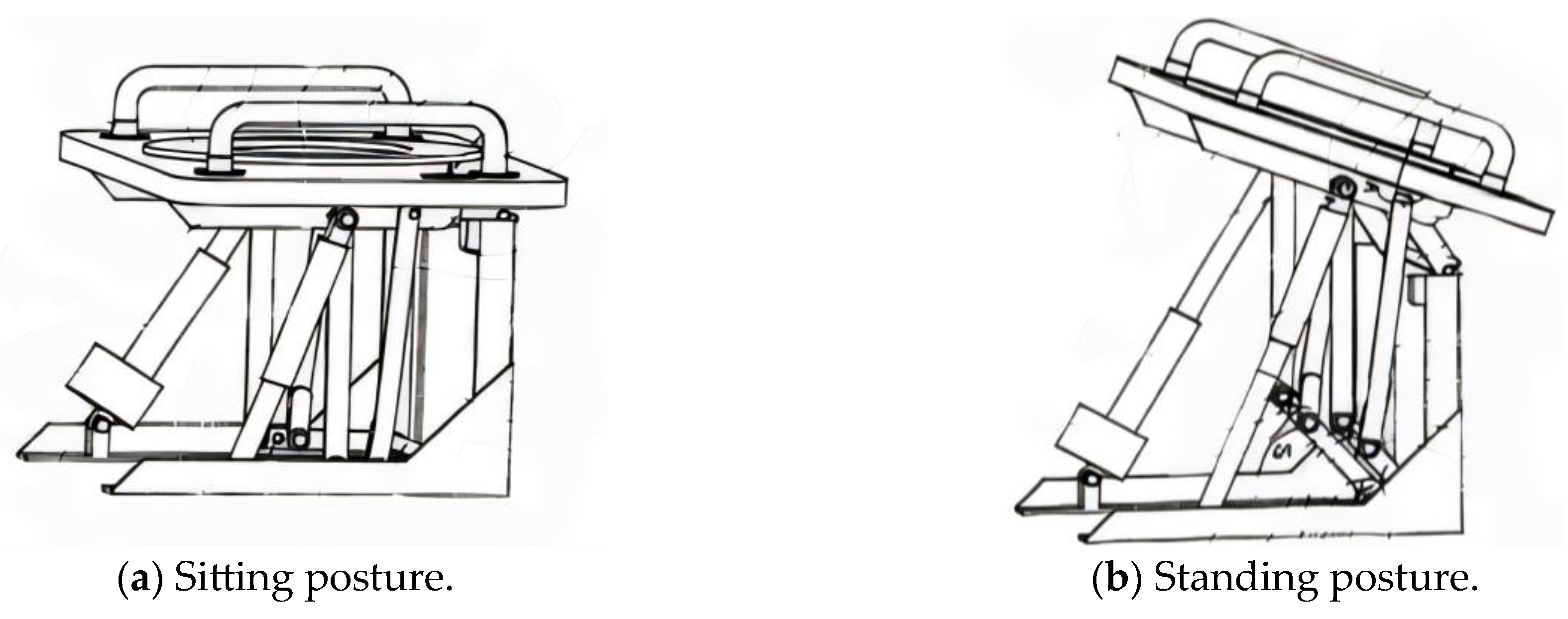
3.3. Apparatus for Lifting Movable Base of Toilet [5]
- The seat link is positioned too high, requiring users to stand on their tiptoes, which increases the risk of injury.
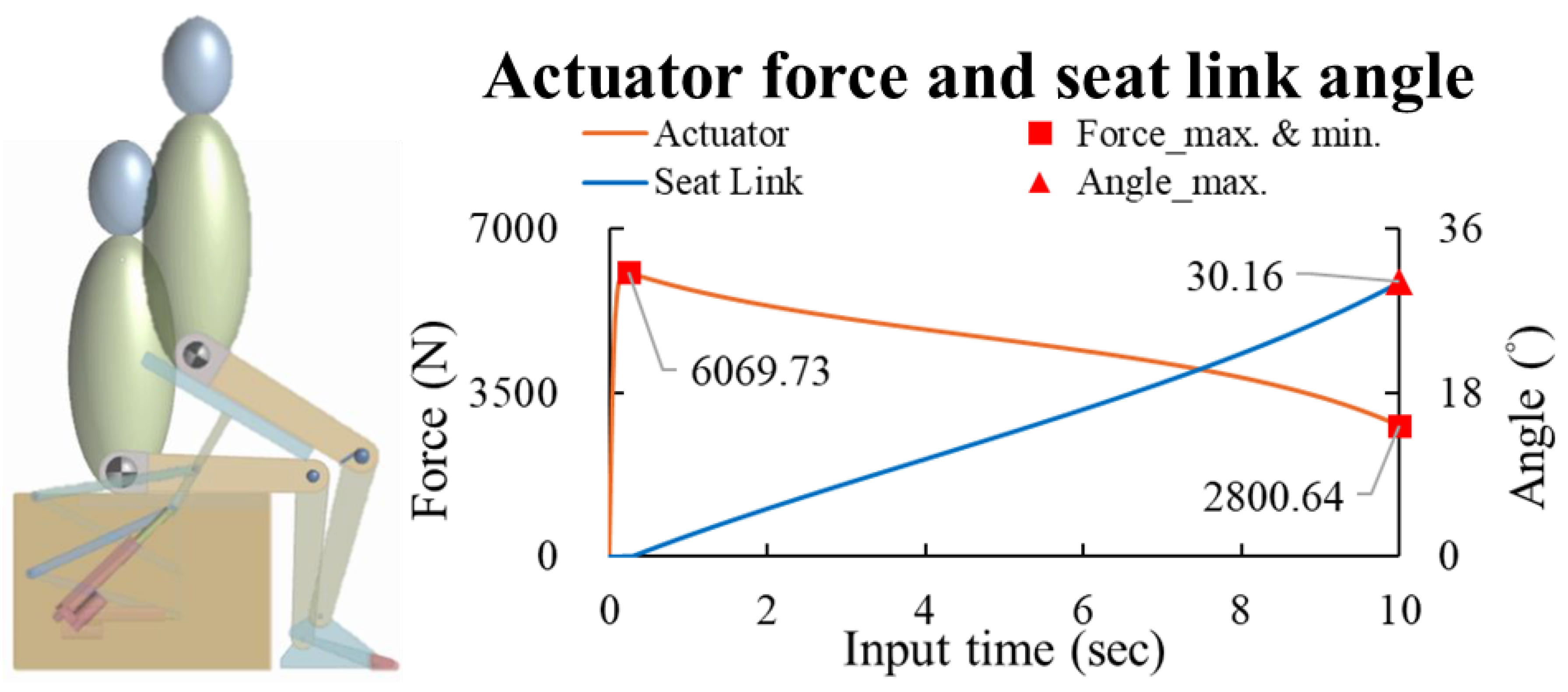
- The seat link’s rotation angle is only 30.16°, which fails to accommodate the natural sit-to-stand movement.
- The actuator’s placement is suboptimal, resulting in an excessively high actuator force requirement (6070 N).
3.4. Heavy Duty Power-Assisted Toilet Seat Lift Assembly [6]
- The excessive forward movement in the seat link causes significant forward bending of the calf, which may increase the risk of injury.
- The rotation angle of the seat link is only 26.38°, which fails to meet the movement requirements for transitioning from sitting to standing.
4. Mechanism Design
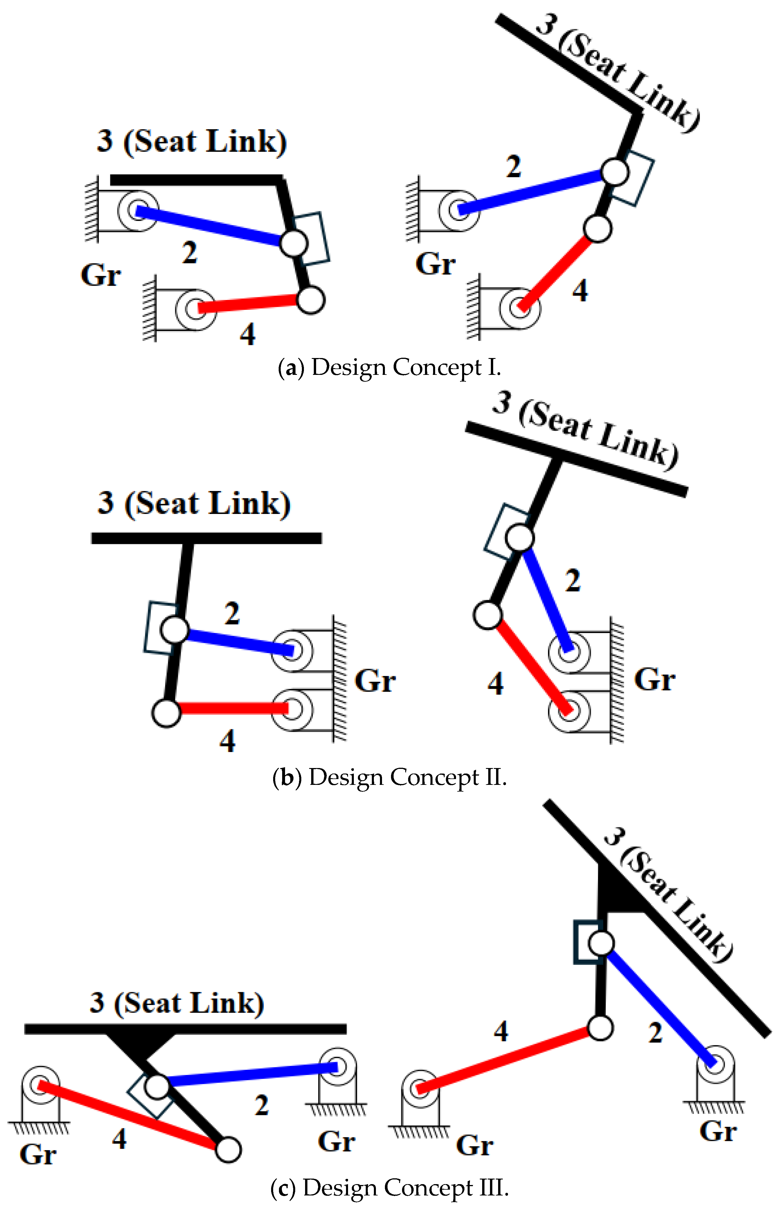
4.1. Design Concepts
4.2. Design Requirements and Constraints
- The seat link must be a coupler link and not be adjacent to the ground link.
- The angular displacement of the seat link (from sitting to standing) should exceed 45°.
- Tiptoeing must be avoided. During operation, the front edge of the seat should move both forward and upward.
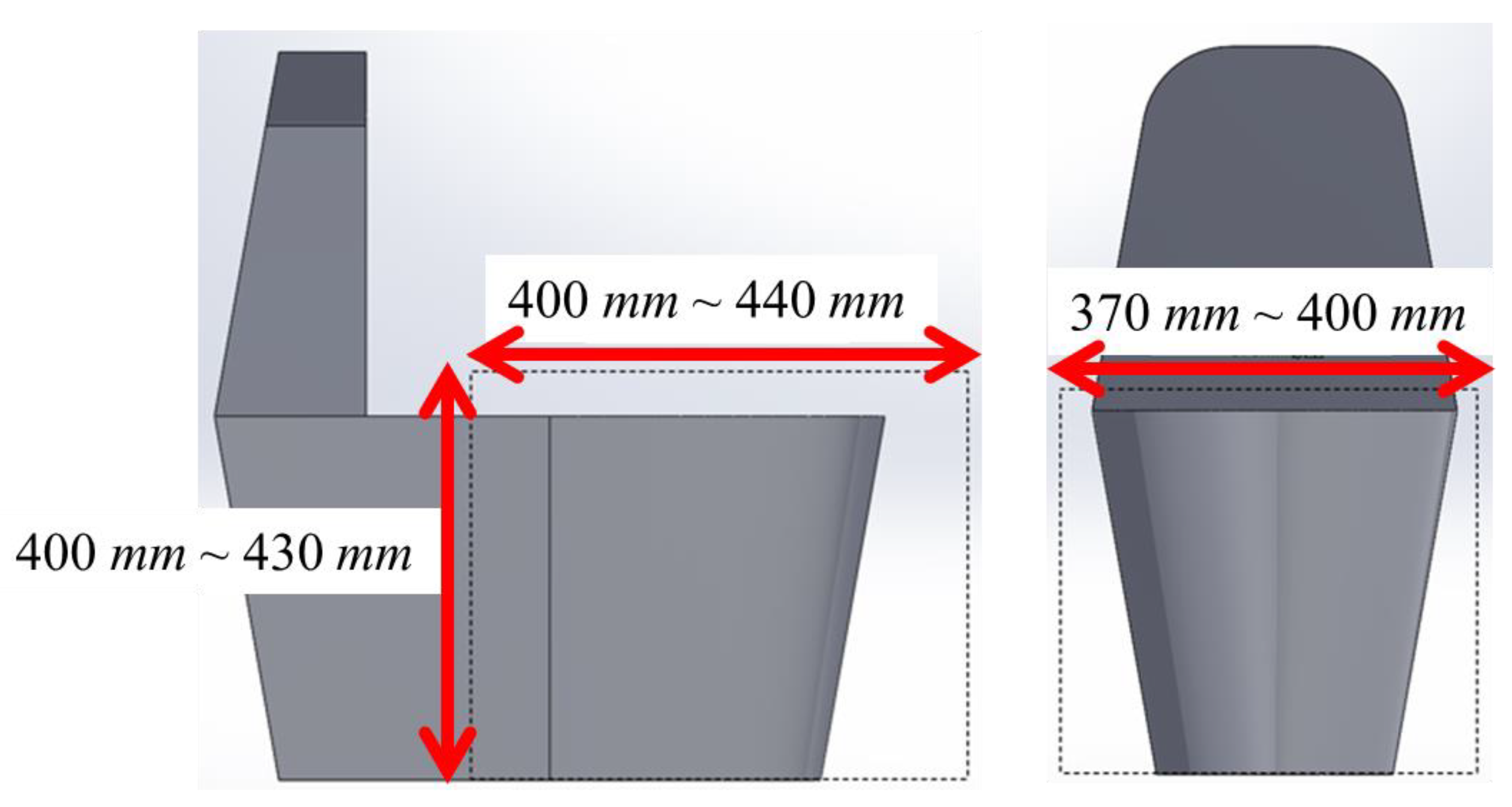
- The dimensions of the auxiliary standing toilet chair must be within a depth of 400 mm–440 mm, a width of 370 mm–400 mm, and a height of 400 mm–430 mm, as shown in Figure 12.
- The standing function can be achieved by using two actuators.
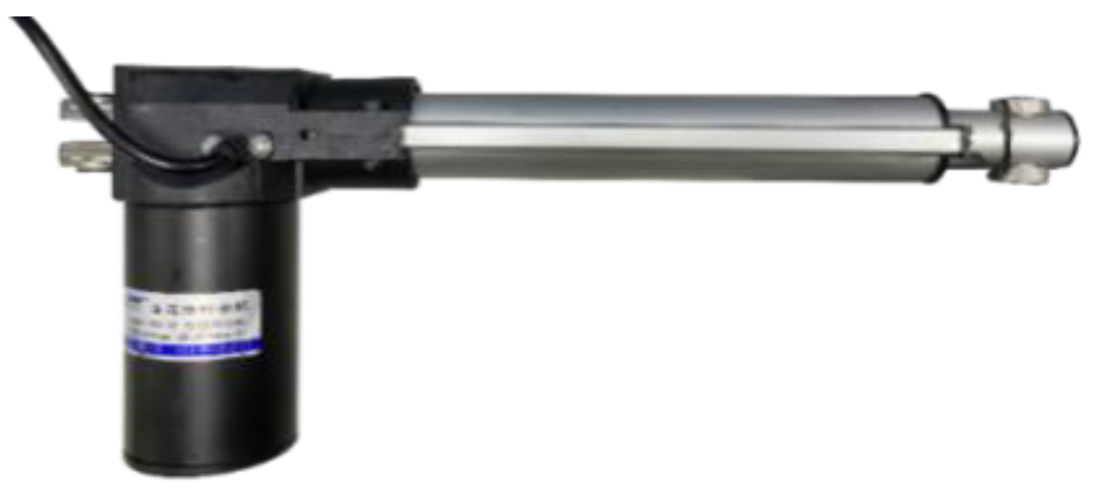
- In this study, the stroke and speed of the actuator are 150 mm and 18 mm/s, and the maximum driving force is 2000 N, as shown in Figure 13. This allows the seat to reach the standing position in approximately 10 s.
4.3. Kinematic Design, Kinematic Analysis, and Driving Force Analysis
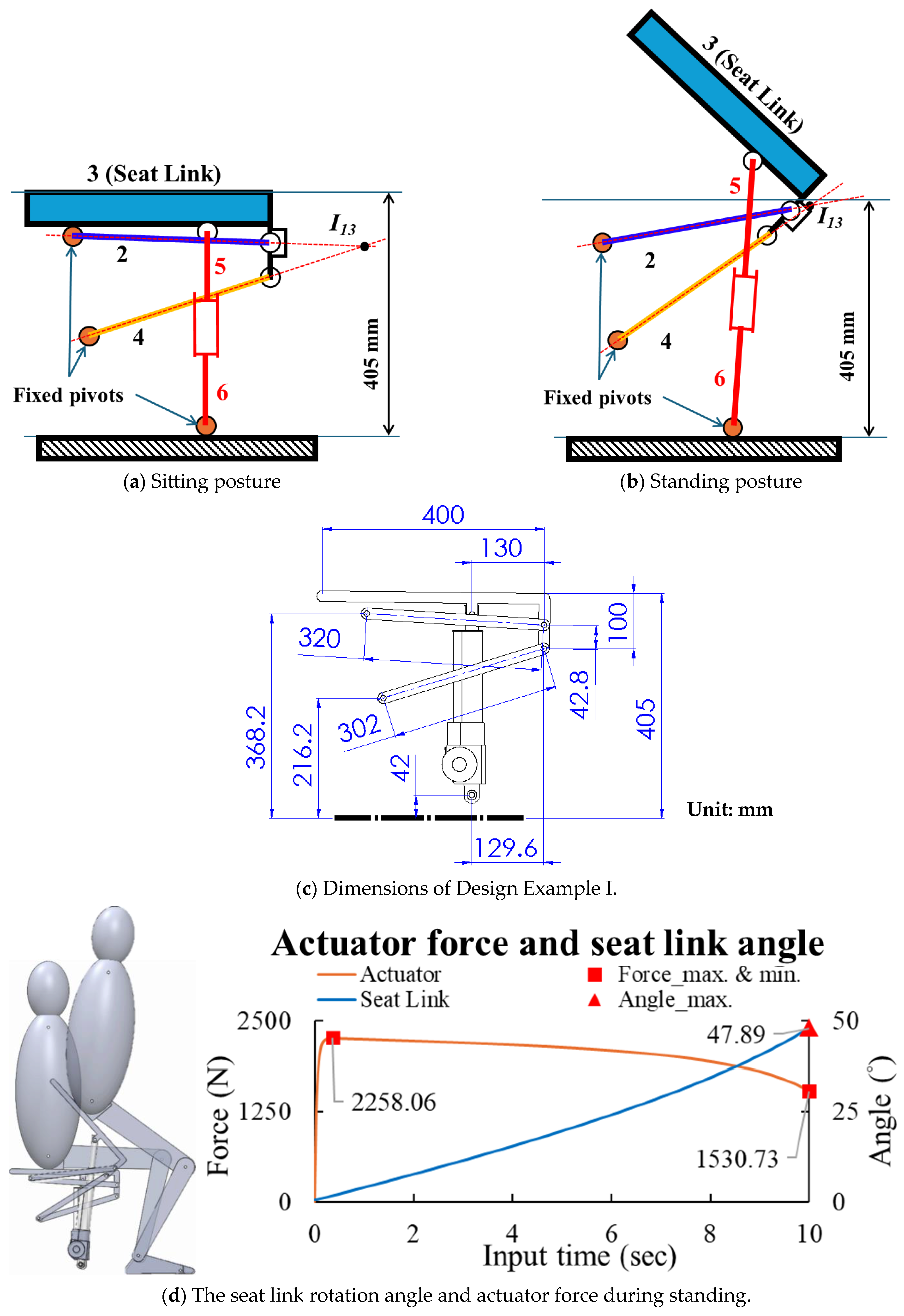
4.3.1. Design Concept I
Design Example I
- The seat link rotates 48° during the sit-to-stand transition.
- The height dimensions meet the design requirements of 400 mm to 430 mm.
- The standing function is achieved using 2 actuators with a stroke of 150 mm, a speed of 18 mm/s, and an actuator force of 4000 N (2 × 2000 N).
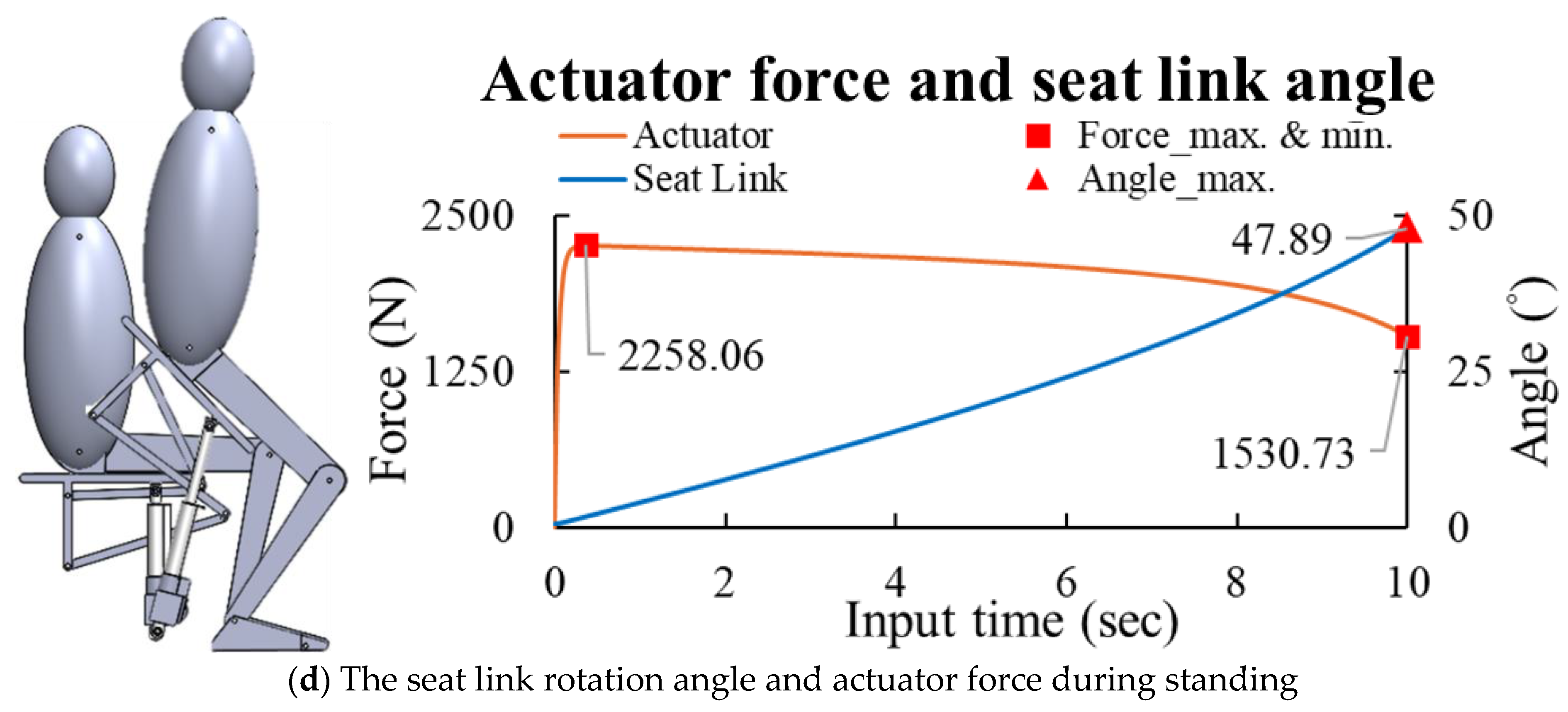
- For a person weighing 150 kg (1500 N), the maximum required actuator force is 2258 N, less than 4000 N, as shown in Figure 14d. This design meets all specified constraints.
4.3.2. Design Concept II
- (a)
- Design Example II
- The seat link rotates 45° during the sit-to-stand transition.
- The height dimensions meet the design requirements of 400 mm to 430 mm.
- The standing function is achieved using 2 actuators with a stroke of 150 mm, a speed of 18 mm/s, and an actuator force of 4000 N (2 × 2000 N).
- For a person weighing 150 kg (1500 N), the maximum required actuator force is 2265 N < 4000 N, as shown in Figure 15d. This design meets all specified constraints.
- (b)
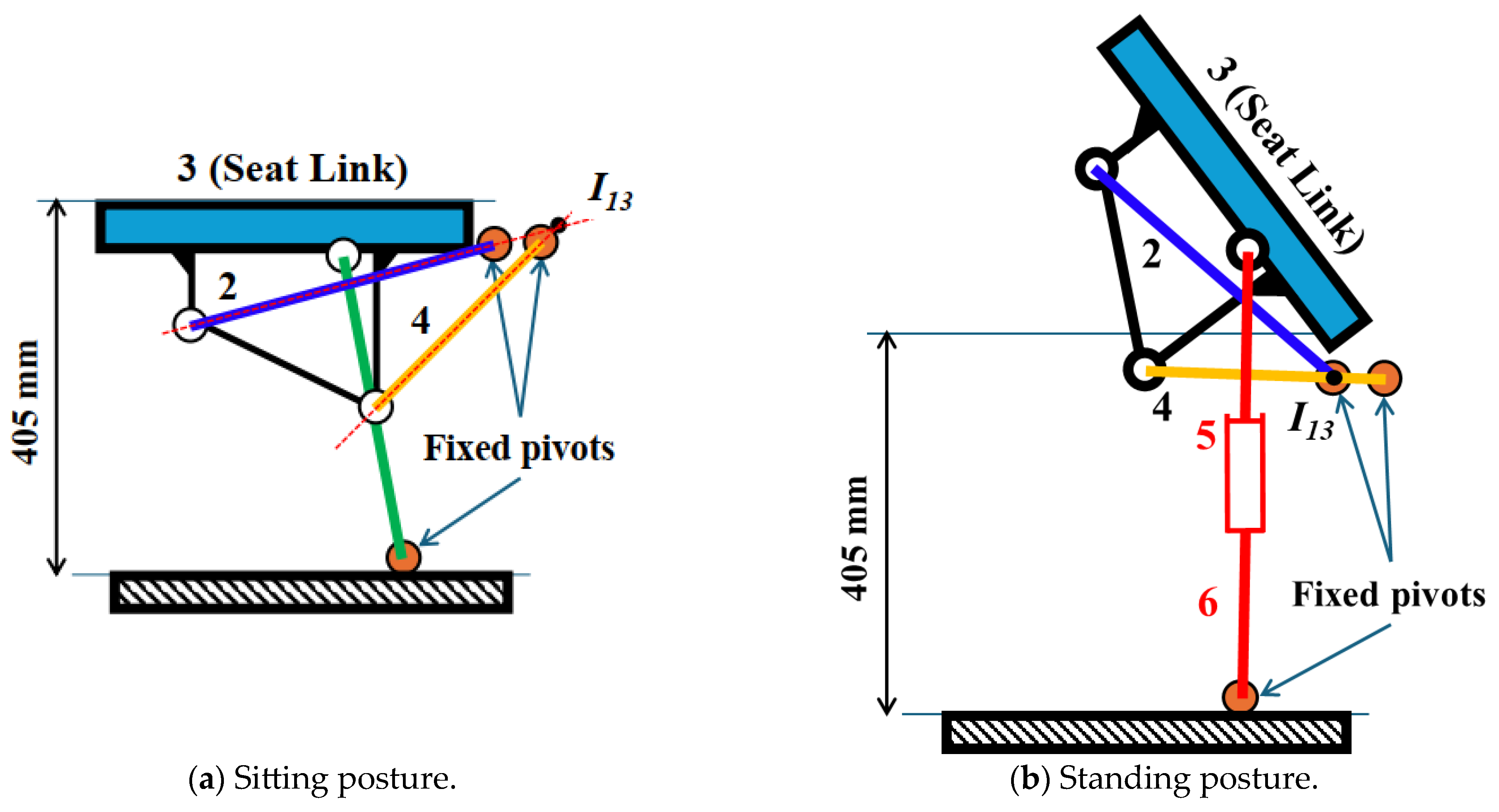
- Design Example III
- The seat link rotates approximately 45° during the sit-to-stand transition.
- The height dimensions meet the design requirements of 400 mm to 430 mm.
- The standing function is achieved using 2 actuators with a stroke of 150 mm, a speed of 18 mm/s, and an actuator force of 4000 N (2 × 2000 N).
- For a person weighing 150 kg (1500 N), the maximum required actuator force is 2361 N < 4000 N, shown in Figure 16d. This design meets all specified constraints.
4.3.3. Design Concept III
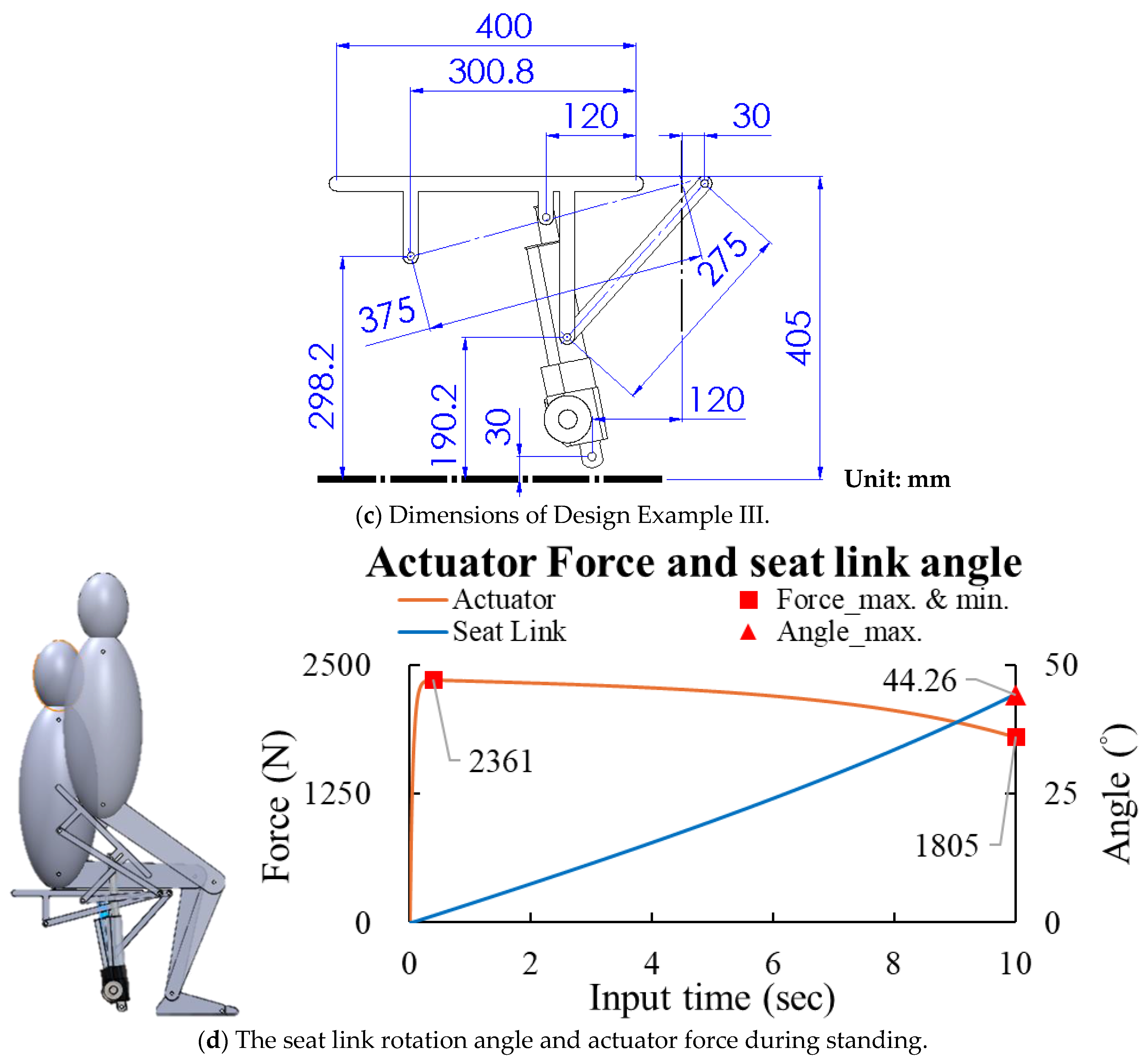
Design Example IV
- The seat link rotates 41.5° during the sit-to-stand transition.
- The height dimensions meet the design requirements of 400 mm to 430 mm.
- The standing function is achieved using two actuators with a stroke of 150 mm, a speed of 18 mm/s, and an actuator force of 4000 N (2 × 2000 N).
- For a person weighing 150 kg (1500 N), the maximum required actuator force is 5364 N > 4000 N, as shown in Figure 17d. This does not satisfy the design constraints.
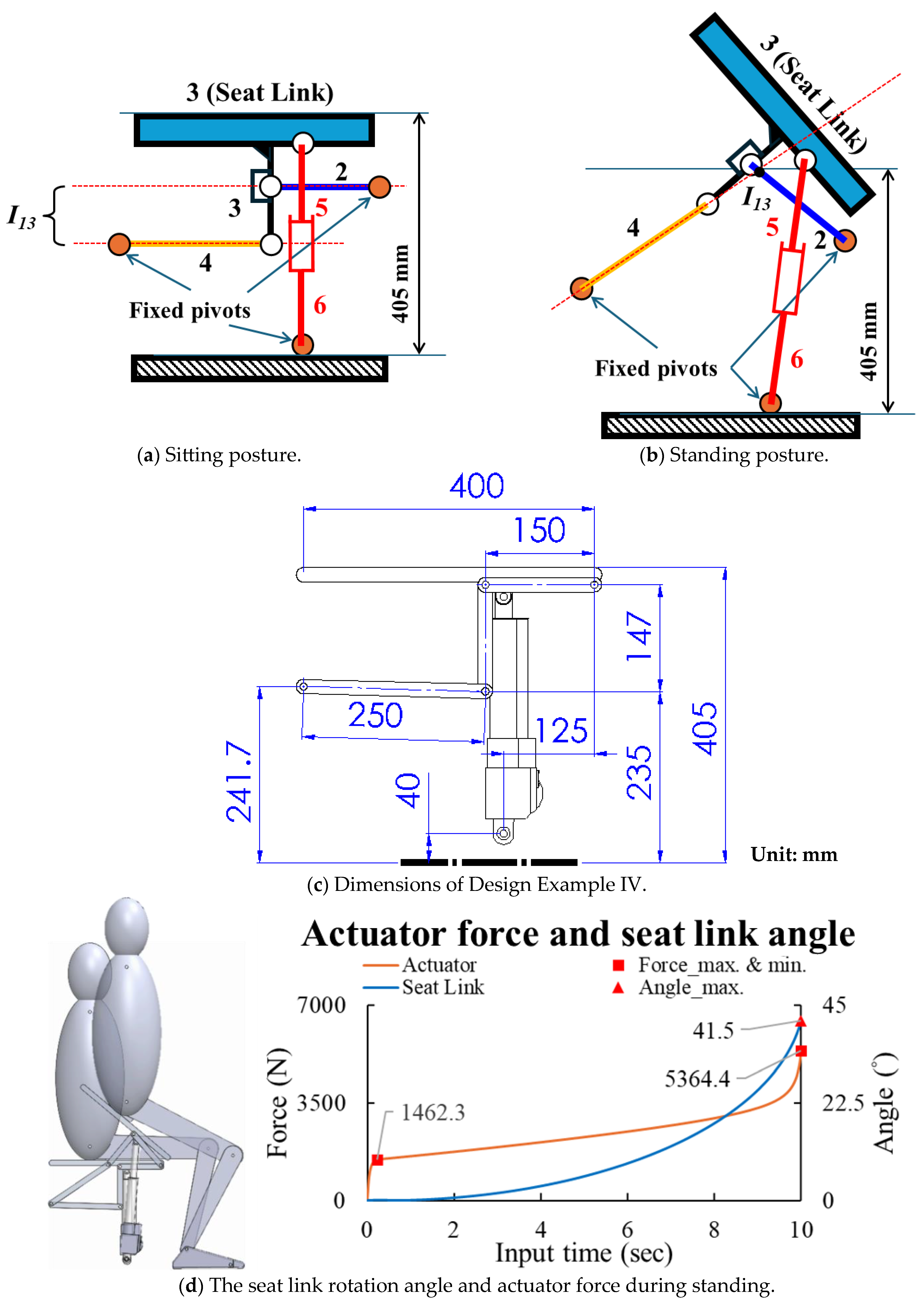
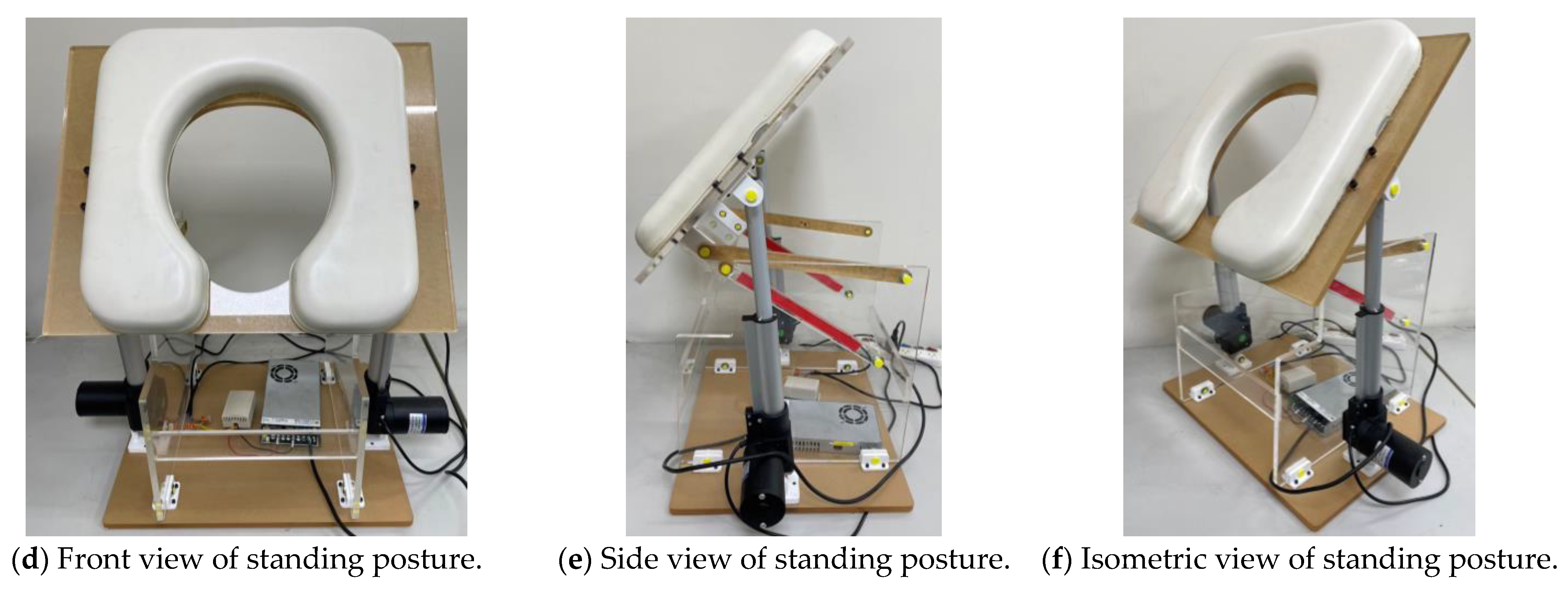
5. Engineering Design and Prototyping
6. Conclusions
- The actuator directly drives the seat link, which rotates around the center of the knee (instant center I13) as much as possible. Its rotation angle reaches 48°, thus eliminating the need for tiptoeing or the downward movement of the hips.
- The toilet chair mechanism is a four-bar linkage that utilizes only revolute pairs, simplifying production and maintenance.
- When assisting a 150 kg person to stand, the maximum required actuator force is only 2258 N, with each actuator bearing 1129 N. This significantly reduced force requirement results in an improved energy efficiency.
Author Contributions
Funding
Data Availability Statement
Acknowledgments
Conflicts of Interest
References
- Hirschfeld, H.; Thorsteinsdottir, M.; Olsson, E.; Pai, Y.-C.; Wening, J.D.; Runtz, E.F.; Iqbal, K.; Pavol, M.J. Coordinated Ground Forces Exerted by Buttocks and Feet Are Adequately Programmed for Weight Transfer during Sit-to-Stand. J. Neurophysiol. 1999, 82, 3021–3029. [Google Scholar] [CrossRef] [PubMed]
- Sato, S.; Mizuma, M.; Kawate, N.; Kasai, F.; Watanabe, H. Evaluation of Sit-to-Stand Motion Using a Pressure Distribution Measurement System—Effect of Differences in Seat Hardness on Sit-to-Stand Motion. Disabil. Rehabil. Assist. Technol. 2010, 6, 290–298. [Google Scholar] [CrossRef] [PubMed]
- Yu, S.-F. Toilet Aid for the Aged. TW M579023, 11 June 2019. [Google Scholar]
- Huang, K.-Y. Research and Development of a Lifting Mechanism for Toilets. Master’s Thesis, Taipei University of Technology, Taiper, Taiwan, 2011. [Google Scholar]
- Song, S.Y. Apparatus for Lifting Movable Base of Toilet. U.S. Patent 11160424 B2, 2 November 2021. [Google Scholar]
- Houston, J.; Freidenberger, R. Heavy Duty Power-Assisted Toilet Seat Lift Assembly. U.S. Patent 6154896 A, 5 December 2000. [Google Scholar]
- Osborn, A.F. Applied Imagination: Principles and Procedures of Creative Thinking; Scribner: New York, NY, USA, 1957. [Google Scholar]
- Yan, H.-S. Creative Design of Mechanical Devices; Springer Science & Business Media: Berlin/Heidelberg, Germany, 1998. [Google Scholar]
- Hsu, M.; Chen, H.-Y.; Liu, J.-Y.; Chen, C.-L. Dual-Purpose Wheelchair Mechanism Designs. In Proceedings of the International MultiConference of Engineers and Computer Scientists, Hong Kong, China, 5–7 July 2009; Volume 2, pp. 18–20. [Google Scholar]
- Hsieh, L.-C.; Chen, T.-H. The Innovative Design and Prototype Verification of Wheelchair with One Degree of Freedom to Perform Lifting and Standing Functions. In Proceedings of the 3rd International Conference on Mechanical Engineering and Automation Science (ICMEAS 2017), Birmingham, UK, 13–15 October 2017; Volume 280, p. 012027. [Google Scholar] [CrossRef]
- Hsieh, L.-C.; Chen, T.-H. The Systematic Design and Prototype Verification of the Wheelchair with Standing and Tilting Functions. J. Chin. Soc. Mech. Eng. 2020, 41, 49–58. [Google Scholar]
- Yuan, Z.; Gilmartin, M.J.; Douglas, S.S. Optimal Mechanism Design for Path Generation and Motions With Reduced Harmonic Content. J. Mech. Des. 2004, 126, 191–196. [Google Scholar] [CrossRef]
- Hsieh, W.-H. Kinematic Synthesis of Cam-Controlled Planetary Gear Trains. Mech. Mach. Theory 2009, 44, 873–895. [Google Scholar] [CrossRef]
- Li, H.; Zhang, Y. Seven-Bar Mechanical Press with Hybrid-Driven Mechanism for Deep Drawing; Part 1: Kinematics Analysis and Optimum Design. J. Mech. Sci. Technol. 2010, 24, 2153–2160. [Google Scholar] [CrossRef]
- Hsieh, W.-H.; Tsai, C.-H. On a Novel Press System with Six Links for Precision Deep Drawing. Mech. Mach. Theory 2011, 46, 239–252. [Google Scholar] [CrossRef]
- Chen, F.-C.; Tzeng, Y.-F.; Chen, W.-R. On the Mechanism Design of an Innovative Elliptical Exerciser with Quick-Return Effect. Int. J. Eng. Technol. Innov. 2018, 8, 228–239. [Google Scholar]


Disclaimer/Publisher’s Note: The statements, opinions and data contained in all publications are solely those of the individual author(s) and contributor(s) and not of MDPI and/or the editor(s). MDPI and/or the editor(s) disclaim responsibility for any injury to people or property resulting from any ideas, methods, instructions or products referred to in the content. |
© 2025 by the authors. Licensee MDPI, Basel, Switzerland. This article is an open access article distributed under the terms and conditions of the Creative Commons Attribution (CC BY) license (https://creativecommons.org/licenses/by/4.0/).
Share and Cite
Hsieh, L.-C.; Chen, T.-H.; Lai, P.-C.; Huang, T.-M. The Engineering Design and Prototyping of an Auxiliary Standing Toilet Chair Driven by Electric Cylinders. Machines 2025, 13, 402. https://doi.org/10.3390/machines13050402
Hsieh L-C, Chen T-H, Lai P-C, Huang T-M. The Engineering Design and Prototyping of an Auxiliary Standing Toilet Chair Driven by Electric Cylinders. Machines. 2025; 13(5):402. https://doi.org/10.3390/machines13050402
Chicago/Turabian StyleHsieh, Long-Chang, Tzu-Hsia Chen, Po-Cheng Lai, and Tsung-Ming Huang. 2025. "The Engineering Design and Prototyping of an Auxiliary Standing Toilet Chair Driven by Electric Cylinders" Machines 13, no. 5: 402. https://doi.org/10.3390/machines13050402
APA StyleHsieh, L.-C., Chen, T.-H., Lai, P.-C., & Huang, T.-M. (2025). The Engineering Design and Prototyping of an Auxiliary Standing Toilet Chair Driven by Electric Cylinders. Machines, 13(5), 402. https://doi.org/10.3390/machines13050402