Abstract
This study provides a set of designs, simulations and experiments for developing an actuating method for manual pipettes. The goal is to enable robotic manipulation and automatic pipetting, while using manual pipetting devices. This automation is designed to be used as a flexible alternative tool in small and medium-sized biochemistry laboratories that do not possess proper automated pipetting technology, in order to relieve the lab technicians from the tedious, repetitive and error-prone process of manual pipetting needed for the preparation of biological samples. The selected approach is to use a set of pressure-controlled pneumatic cylinders in order to control the actuation and force of the pipettes’ manual buttons. This paper presents a mechanical design, analysis, pneumatic simulation and functional robotic simulation of the developed device, and a comparison of possible pneumatic solutions is presented to explain the selected actuation method. Remote pneumatic pressure sensing is employed in order to avoid electrical sensors, connectors and wires in the area of the actuators, thus expanding the possibility of working in some electromagnetic-compatible environments and to simplify the connecting and cleaning process of the entire device. A functional simulation is conducted using a combination of software packages: Fluidsim for pneumatic simulation, URSim for robot programming and CoppeliaSim for application integration and visualization. Experimental validation is conducted using off-the-shelf pneumatic components, assembled with 3D-printed parts and mounted onto an existing pneumatic gripper. This complete assembly is attached to an industrial collaborative robot, as an end effector, and a program is written to test and validate the functions of the complete device. The in-process actuators’ working pressure is recorded and analyzed to determine the suitability of the proposed method and pipetting ability. Supplemental digital data are provided in the form of pneumatic circuit diagrams, a robot program, simulation scene and recorded values, to facilitate experimental replication and further development.
1. Introduction
In small and medium-sized biochemistry laboratories, samples’ preparation and analysis often still rely on manual process steps, and in many cases, these involve manual pipetting. Manual sample preparation (i.e., pipetting) requires that lab technicians should operate with precise, fast and highly repetitive arm movements, while staying focused for long periods of time (hours). This has already been proven to generate arm pains [1] and also makes the process prone to operator errors and the samples’ invalidity. Considering the global technological state of the art, automating this pipetting process is the obvious choice [2,3,4]. Many companies around the world are meeting this demand by offering a large variety of automated pipetting solutions, for example [5,6,7]. The number of manufacturers and offered solutions is quite large, not surprisingly, considering the high increase in analyses following the COVID-19 pandemic. There are also custom-designed pipetting robots/automations [8,9,10] and even fully integrated robotic solutions that re-use electronic or manual pipettes [11,12,13]. Unfortunately, not all labs can obtain such specially designed devices, and this sends them looking for alternate automation solutions, either ones that are more flexible/expandable or just cheaper, usually while reusing their functional equipment. Using the already present manual pipettes and the required accessories makes for an easier transition, less training and, if needed, the ability to quickly revert to the manual process.
A solution that can be accepted by small labs is to install a robotic manipulator for manual pipettes, replicating technicians’ movements, as long as no special safety equipment or extensive lab installations are required. This means using widely available collaborative robotic arms and using the existing lab equipment. The authors have already approached this aspect in previous work [14] by exploring the robotized gripping and manipulation of a common manual pipette. Other researchers have also explored a similar path, using collaborative robots (cobots) with modified grippers [15,16] to actuate manual pipettes. Different solutions have been identified in the literature—regarding close human–cobot interaction—not only limited to pipetting, by using robotic arms and manipulator structures, showing the opportunity for an appropriate concept and design [17,18,19,20].
The current paper focuses on the need to detect the presence of—and actuate—a manual pipette in the context of robotic manipulation, constrained by several key aspects:
- -
- The designed device/pipette actuating assembly (i.e., robot’s end effector) should be simple in construction and its functions easy to understand by the users;
- -
- The device should use off-the-shelf, readily available components, and should rely on simple and affordable manufacturing techniques, to ensure its facility of reproduction;
- -
- The connectors for the actuators should be easy to decouple, allowing for fast and uncomplicated dismantling in view of the device’s cleaning/disinfecting;
- -
- If possible, no sensitive electronic components should be embedded in the actuating device, allowing for use even in electromagnetic-compatible environments;
The device/end effector, together with the control components, should be designed in such a way that portability between different (collaborative) robot brands and models should be ensured.
The presented solution relies on using pneumatic actuation for gripping the pipette (a constraint imported from previous work), as well as for actuating (pressing) the two buttons of a common manual microliter pipette [21] (one button is for pipetting–aspiration and the dispensing of liquid; the other button is for discarding the disposable liquid collecting tip).
Pneumatics is selected in favor of electric actuation to conform with all the above constraints, although electric actuation using, for example, common hobby servos like [22] was considered.
Another aim of this paper is to have the end effector detect if the manual pipette is grasped by the gripper and if it has a properly attached tip. Considering the state of the art, small force sensors, pneumatic cylinder position sensors or even computer vision could be employed for the detection. To keep the end effector design as simple as possible—yet reliable for unattended robotic tip replacement and pipette changing—a remote pneumatic sensing method was selected and tested, following the authors’ experience and a literature overview [23,24,25,26,27,28,29,30].
So, this paper presents a simplified mechanical design and analysis, the development of a full pneumatic solution and the testing of the robotic pipetting end effector. Prior to the design, the required buttons forces were experimentally determined.
In order to ensure an optimal pneumatic circuit design, and before committing to prototype building, an extensive functional simulation was conducted, using visualization [31,32,33,34] and data exchange between a well-established pneumatic simulator [35,36] and a robot’s offline simulator [37].
Data collected during real-world experiments mirror the behavior of the simulation, with an expected slight offset in values but without affecting the validity of the implemented method.
The proposed solution is appropriate for manual pipettes in the microliter range and can be used with any type of robotic manipulator, as long as it supports end effectors with a (standardized) connecting flange, and at least one analog input, one analog output and four digital outputs are available. The design makes it particularly suitable for collaborative robots like the range from Universal Robots [38]. Adapting for a different brand/model of manual pipette is a matter of modifying the design and reprinting the gripper fingers. Of course, the “new” pipette must fit the strokes of the actuating cylinders. The re-parametrization of the pneumatic circuit (pressure values) would also be needed.
2. Materials and Methods
2.1. Experimental Determination of the Pipette’s Buttons’ Pressing Forces
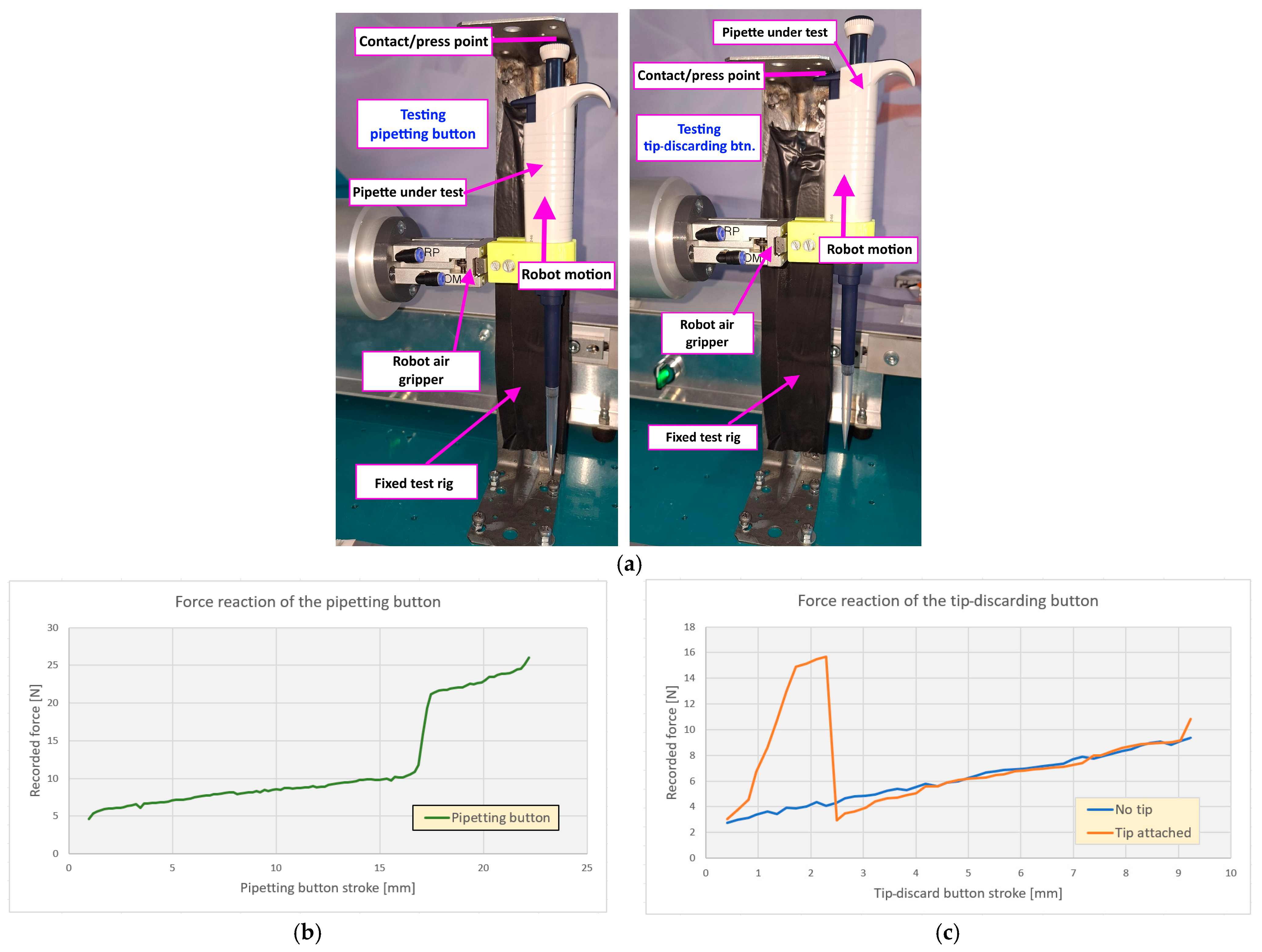
The pipette user manual and datasheet do not contain enough information to properly assess the required forces needed to press the buttons for pipetting and tip release. Subjectively, it was noted that the finger-felt pressing thresholds are very well defined, and the forces required for pressing seem quasi-constant with the buttons’ stroke. From an ergonomic point of view, it seems a well-designed product, suitable for long manual working sessions. But for pneumatic actuation, quantitative force values are needed. The authors devised a simple experiment, mostly using what is already available from previous work [14], as in Figure 1:
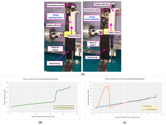
Figure 1.
Robot force test rig and force reaction of pipette buttons: (a) fixed test rig to apply buttons’ forces; (b) pipetting button, including last droplet expel stroke; (c) tip-discarding button, with and without tip.
- -
- The pipette was gripped using the gripper installed on the robot;
- -
- A fixed rig was installed on the robot table in such a way that the pipette could be vertically raised by the robot until the pipetting button contacted a rigid protruding shelf affixed to the rig;
- -
- The robot then started to further raise the pipette and press the button against the shelf, while recording the vertical force registered by its force–torque sensor, for every 0.2 mm of lift; it was repeated 10 times, with all data averaged;
- -
- A similar test was conducted for the tip release/discard button, with a tip properly attached to the pipette.
The results from the above experiment are presented in Figure 1, as average force values dependent on buttons’ stroke/travel. It can be observed that the forces are slightly increasing per each individual travel segment (if no tip), so the highest value (at segment end) is considered for further calculation. For the discarding of the tip, a higher force than recorded can be used without issues.
2.2. Pressure Level Selection
Once the required forces and strokes are known, the pressure in the circuits can be selected, and the buttons’ actuators can be sized. But to determine the optimal supply pressure for the entire actuating assembly and sizing for the buttons’ actuators, several factors must be considered:
- -
- The gripper for the pipette must conform to the previous findings [14], which impose approx. 2.5 bar for clamping the pipette;
- -
- The buttons actuators must exert a minimum of 25 N but not more than 35 N, to protect the pipette from being forced or otherwise displaced in the gripper;
- -
- The pressure control valve and sensor should work in their linear region (keep away from limits), and the pressure should be on the low side (to help reduce compressed air consumption);
- -
- Components that are in the standard product range of manufacturers are desired, so that they are cheaper and readily available;
- -
- The tubing going from the robot base to the actuators should be as simple as possible, meaning that a minimum number of tubes should be considered.
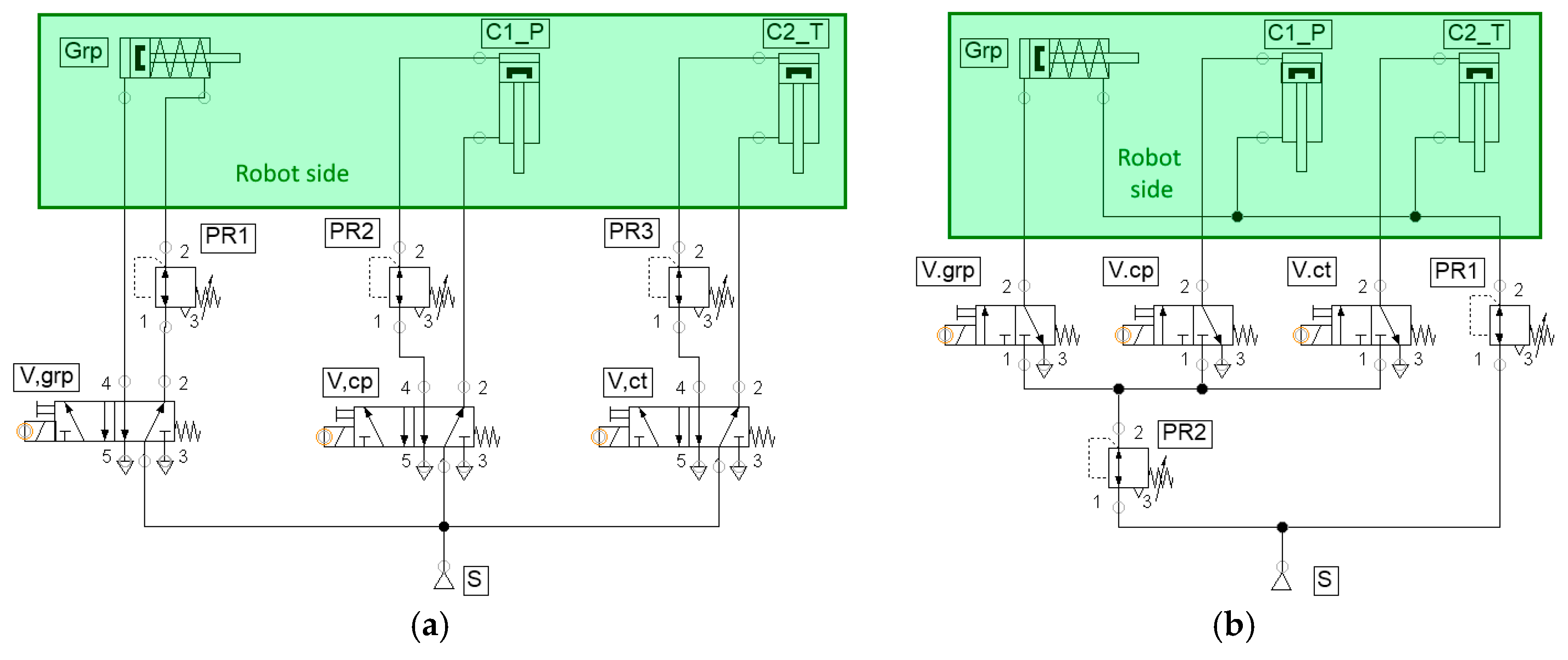
Considering the above, several pneumatic solutions are available, and two principial options are presented, a standard schematic (Figure 2a) and an optimized schematic (Figure 2b).
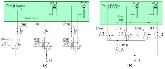
Figure 2.
Principial pneumatic actuation circuits: (a) classic 3-cylinder approach with force regulation; (b) optimized tubing with unified force regulation and pressurized base position imposed. Grp is the gripper, C1_P is the pipetting cylinder, C2_T is tip discard cylinder, V(x) are cylinder control valves, PR(x) are pressure regulators, and S are air supply units.
The simple/optimized variant was opted for, as it complies with all requirements and—very important to the potential end user (i.e., the lab technician)—is simpler to connect pneumatically. In this variant, it can be observed that the tubes for the gripper’s closing and actuator cylinders’ retraction are unified in a single tube, hence using a default preset pressure, which is manually regulated during the system’s commissioning and then continuously applied to the three actuators. The reason for this is that buttons’ cylinders should be forced to be retracted until commanded to extend (as if they would have a spring inside), so that they do not interfere with acquiring the pipette. At the same time, the gripper should be always forced closed when there is no opening command (although here, there is a spring inside, as it is a normally closed gripper).
2.3. Cylinders Sizing
Considering the above, sizing the buttons’ actuator cylinders’ bores involves solving for a maximum needed actuation force of ~35 N within the above condition, while limiting the cylinder selection to standard small-bore cylinders (8 … 25 mm). We will exclude 8 mm and 25 mm from the start, the first being too exotic and the last being actually too bulky—generating a larger and heavier assembly. The remaining standard small-bore cylinders are 10, 12, 16 and 20 mm [39,40].
Equation (1) gives the theoretical force exerted by any of the two button cylinders while being supplied with the retract pressure, :
where is the resultant actuation force of the cylinder; is the extending force; is the opposing retracting force (always active); is the pressure in the extend (back) chamber; is the pressure in the retract (front) chamber; is a coefficient linked to the manual pressure regulator, which will vent into the atmosphere when the downstream overpressure will be approximately 100 mbar higher than regulated pressure; is the piston diameter; and is the piston rod diameter. At bar, we obtain N for mm, and at 5.5 bar, we obtain N for mm.
Considering we are aiming for N (±10%), we must solve Equation (1) for using a in the range of (3.5 … 5.5 bar), bar and , as in Equation (2).
where bar. The rod has an average diameter of 6 mm for the considered cylinders, so we start with this value and adapt (to 4 or 8 mm) after the first iteration if necessary.
The results show that bar exceeds for a standard mm (with mm), bar is spot-on for mm ( mm) and bar is spot-on for mm ( mm). At the same time for bar, the 20 mm cylinder exerts over 100 N, a large force that can be problematic to the pipette or the gripper assembly, so we will also drop this cylinder size. What remains to be used are the 16 mm cylinders and 12 mm cylinders, both sizes being equally suitable, providing a corresponding pressure control.
Since the theoretical pressures and volume calculation are in a simplified form that do not account for various loss types during functioning, pressure level tuning (slightly increasing) for the simulation and for the experiments will be required.
2.4. Cylinders Stroke Selection
Ideally, both buttons’ cylinders will have the same standard diameter and the standard same stroke, for a simpler and cheaper setup. The minimum required stroke for the pipetting action must consider the motion of the pipetting button, as described in the pipette’s operating manual [41], and the vertical motion of the gripper during the grasping of the pipette. The resulting sum can be observed in Figure 3a and is composed of the following measured lengths: pipetting stroke mm, droplet expel stroke mm, vertical gripper stroke mm and free-for-approach gap mm. Considering the above, a standard stroke of 50 mm is optimal. For the tip release stroke, the required total length is obviously smaller, but we will select the same cylinder as for the pipetting actuation, with a free stroke mm and discarding stroke mm. What remains is to install it in the correct vertical position.

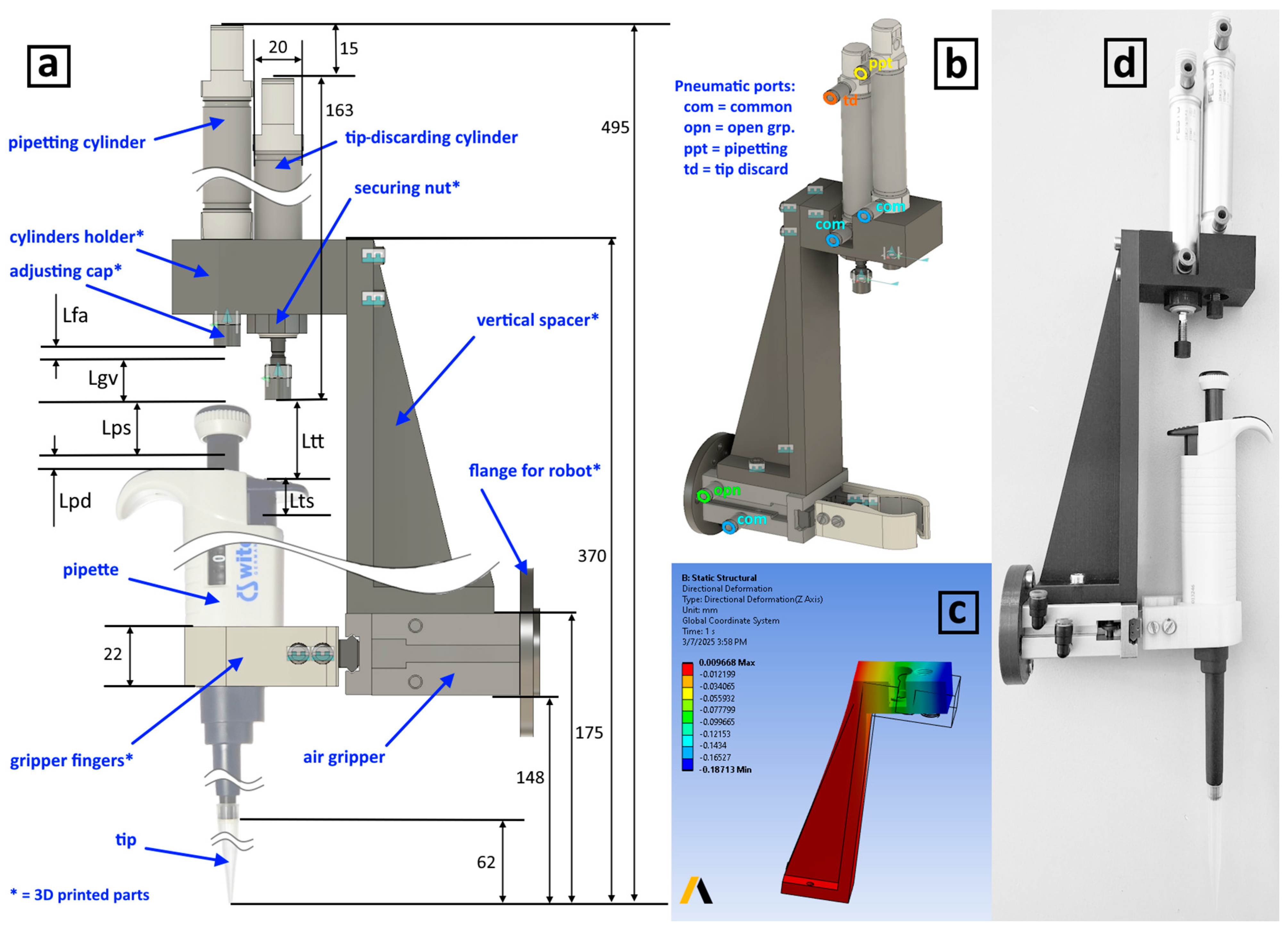
Figure 3.
Pneumatic pipette actuator assembly: (a) components’, dimensions’ and rods’ travels; (b) isometric view with pneumatic ports’ identification; (c) FEA displacement analysis; (d) picture of the actual assembly, holding the pipette.
Following the cylinder dimensioning procedure, we can select either a 12–50 or a 16–50 round-type cylinder from the established manufacturers. Since we already have in our lab several Festo DSNUP-16-50-P-A (Esslingen, Germany) cylinders [42], we can conduct the simulation and experimenting based on them.
Once the cylinders are selected, the fixture for them can be designed and 3D modeled, in such a way that later it can be 3D printed and attached on top of the existing gripper. The vertical spacer (from the gripper to the cylinders) is designed as a separate part from the cylinder holder part. After printing, the 2 parts should be attached with 4 screws, and then the cylinders can also be secured in their designed recesses. The tip cylinder has its install position 15 mm lower than the pipette cylinder. This distance is the vertical offset between the stroke end of the pipetting button and the stroke end of the tip release button.
The vertical spacer is quite long and prone to bending under the reaction forces in the cylinders, so it is designed with a reinforcement rib. A finite element analysis (FEA) was conducted on the designed assembly, considering that the assembly is 3D printed with polylactic acid (PLA), and the maximum force exerted by the pipetting cylinder is 35 N. The vertical deformation indicated was low, with a maximum of 0.19 mm, which does not negatively affect the functioning of the device. Nevertheless, each cylinder is provided with a threaded 3D-printed cap on the rod, that can be height-adjusted to compensate and obtain the full required stroke while pressing the pipette’s buttons. Figure 3 presents the modeled layout of the assembled device (Figure 3a,b), an image of the FEA (Figure 3c) and a picture of the real assembly (Figure 3d).
2.5. Pipette Buttons’ Actuation
The manual pipetting procedure, as per the user manual [41], assumes the following process: A pipette with a tip attached is inserted into a reagent tube to a certain depth, having the pipetting button fully pushed. Once in the liquid, the button is slowly released to collect the dosed amount. Pipetting per se is done by pushing the button to release the liquid, followed by a final stronger push to expel any last droplet from the tip. For discarding the used tip, the technician must push the dedicated button, the release being felt as a short peak force.
For the pipetting button’s actuation, its cylinder must be pressure-controlled so that it develops 10–12 N (as concluded in Section 2.1). For final droplet expel (the second actuation phase), the force must be 22–24 N. For the tip release button’s actuation, the other cylinder must be pressure-controlled so that it develops 15–20 N (as per Section 2.1). Since the two cylinders are not actuated at the same time, a single pressure control valve can be used for both, combined with directional control valves for cylinder selection.
2.6. Remote Sensing for the Pipette/Tip
Remote sensing refers in this case to the detection of the presence/absence of the pipette in the gripper and the presence/absence of the tip (attached) prior to starting the pipetting process. Apart from using external cameras or cylinder-mounted position sensors, there are several ways to detect the pipette or the tip, using the air in the cylinders.
When the 16 mm cylinder is supplied with a low pressure of about 2.5 bar, this will yield a resultant extension force of approx. 5 N, which is enough to extend the rod, and the following options are available: to slightly press on the pipette’s button but without being able to push it to far (so the cylinder stops at approx. 30 mm stroke), or to extend the full 50 mm stroke if the pipette is absent. The same applies to the tip release cylinder, except that it stops at approx. 40 mm stroke if the tip is properly attached. Now, considering the above, two approaches are available:
- (a)
- Install a precise (small-flow) flowmeter and compute the volume of air accumulated in the cylinder, as in Figure 4a, framed yellow. A smaller (measured) mass of air (or volume) means that the cylinder encountered the button and stopped: it means that we have a pipette clamped/we have a tip attached;
- (b)
- Install a pressure sensor together with an isolation valve and expand a known volume of air—from an isolation/buffer tank—at a known pressure into the cylinder, as in Figure 4b, framed green. A higher pressure after expansion means that the cylinder did not extend fully, meaning it encountered the button and stopped: it means that we have a pipette clamped/we have a tip attached.

Figure 4.
Options for pneumatic remote sensing circuits: (a) using a flow meter sensor (FM); (b) using an isolation valve (Viso) and tank (Tiso), together with a pressure sensor (PS). C1_P is pipetting cylinder, C2_T is tip discard cylinder, V(x) are cylinder control valves, PR(x) are pressure regulators and S(x) are air supply units.
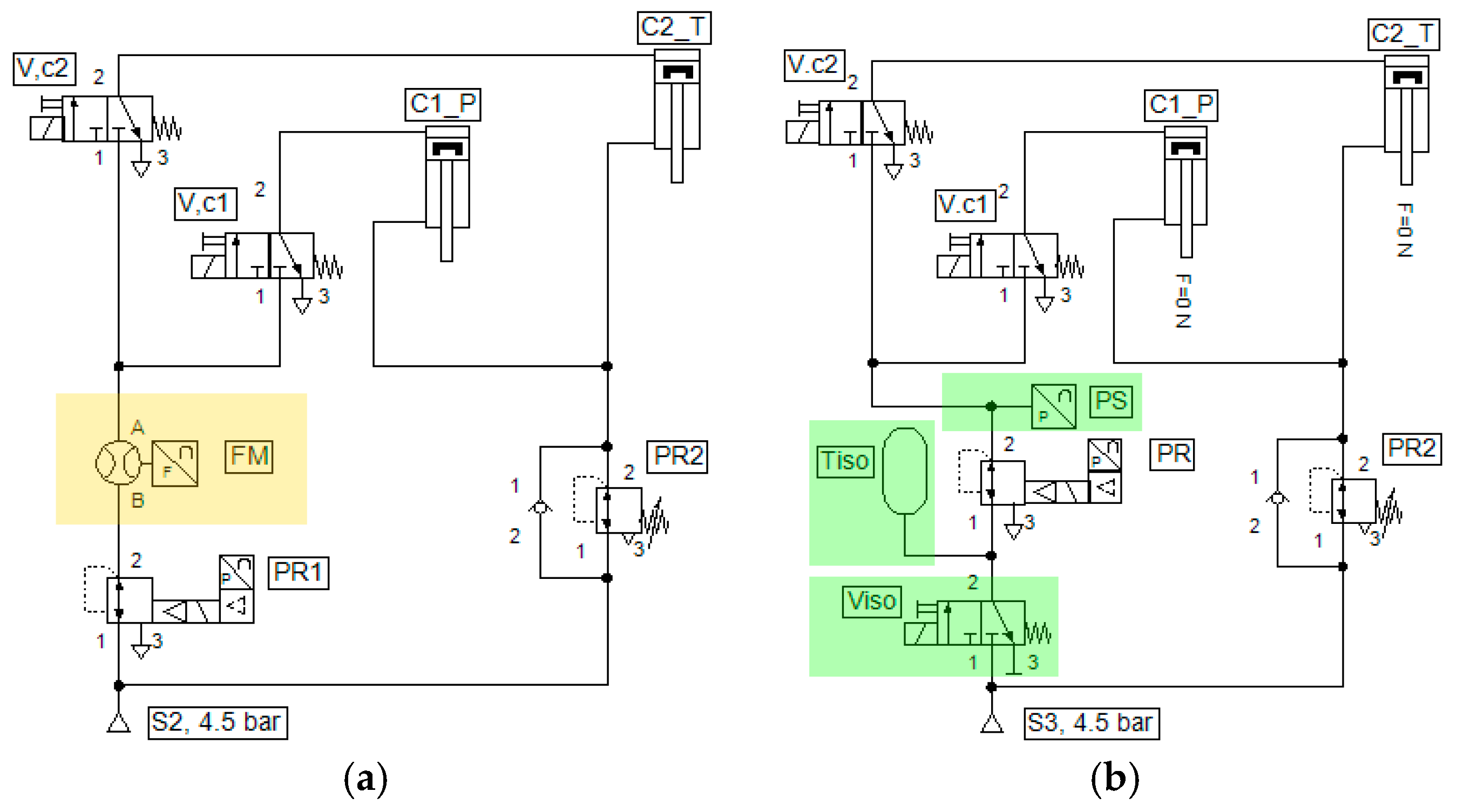
Option (Figure 4b) is simpler (and cheaper), since the proportional pressure control valve [43] already integrates a user-available precise pressure sensor. At the same time, it is trickier because the pneumatic tubes’ internal volumes must be accounted for, and the isolated and expanded volumes need to be balanced to obtain the relevant end pressure and pressure difference (as per Boyle’s law), combined with exerting a pressure that is appropriate for developing the approx. 5 N resultant force. Since the tubes are important not only from the robot perspective but now also from volumetric perspective, standard manufacturers’ tubes with a 3, 4, or 6 mm outer diameter (OD) can be chosen. With 6 mm being a little too stiff and bulky for all four tubes and with the more desirable 3 mm being more exotic and difficult to find in stock, we settled for the most common small diameter tube, which is OD = 4 mm with inside diameter (ID) = 2.5 mm. It is small and flexible enough for the robot, and it has more than enough flow rate.
For the present actuation design, all the valves were installed with their interconnecting circuits in an enclosure installed near the base of the robot. This means that the end effector will contain only the gripper and the two actuating cylinders, alongside with their 4 tubes (1 common tube for retracting and 3 tubes for extending), as in Figure 5c, green-framed components. For these 4 tubes, we impose the lengths of 2 m (for each tube), which is equivalent to a geometric volume for each tube cm3. The geometric volume of a cylinder fully extended (at 50 mm stroke) is cm3; the combined internal volumes of the short tubes, fittings and valves are cm3 (the ones inside the enclosure), and pressure for 5 N at a 30 mm stroke is bar. Considering the theoretical pressure of 4 bar determined if solving for N and mm, we can solve for the volume of the required isolation tank , by arranging Boyle’s law formula, for a 30 mm stroke, as in Equation (3):
where cm3. We obtain the required isolation tank with cm3. Holding onto this volume, for the full 50 mm stroke (pipette absent) we obtain an expanded theoretical pressure of bar. The same applies for the tip detection cylinder, resulting in a pressure at a 40 mm stroke of bar.
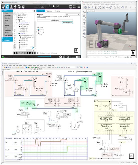
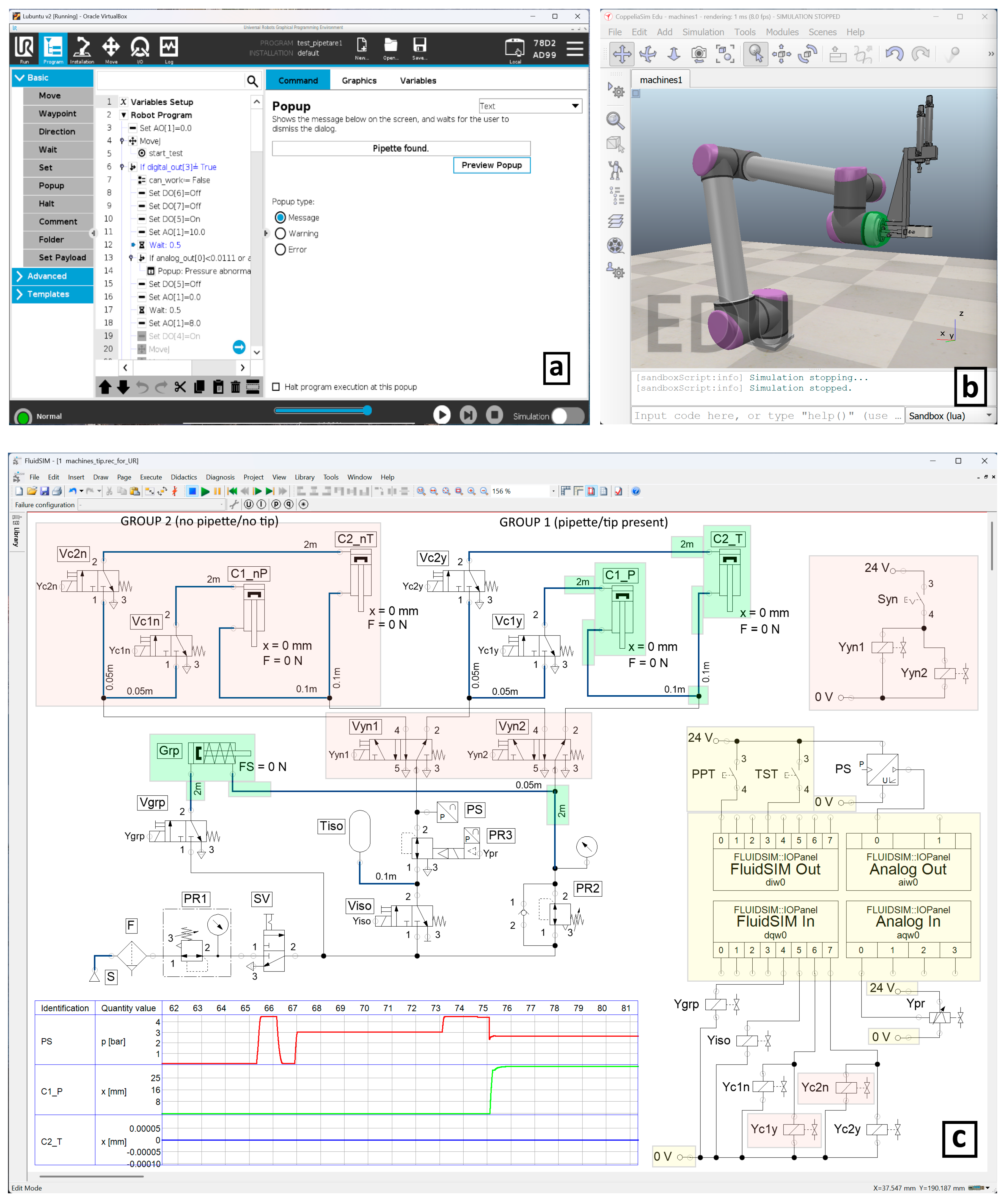
Figure 5.
Simulation of pipette and tip detection and for checking the pipetting process: (a) URSim: offline UR robots programming simulator; (b) CoppeliaSim: robotic simulator, used for motion visualization and data exchange; (c) Fluidsim: pneumatic and electric circuits simulator.
These pressure values by themselves do not mean much, but given the difference of more than 100 mbar between and it can be concluded that pressure sensing via an isolation valve and tank can reliably tell if the pipette is present or absent and, respectively, if the tip is properly attached or not. That 100 mbar value is well within the sensor’s measuring abilities [43], considering that it has a linear analog output of 1.67 V/bar, which is converted by the robot’s analog to a digital converter (16-bit unsigned) [44], resulting in a 0.09 mbar theoretical resolution.
2.7. Functional Simulation
To verify all the above, a simulation environment was constructed, composed of an assembly of software applications. The programs could control the valves to actuate the cylinders, collect sensor data and user events, send these input/output values to a running robot program and visualize the robot trajectories for better process understanding (Figure 5).
The pneumatic schematic (expanded from the concept in Figure 4b), together with the required electric schematic, was simulated using Fluidsim v5 [35] (Figure 5c), the simulation file being available in [S3]. To simulate the possible scenarios of pipette clamped/tip attached and pipette missing/tip not attached, two groups of cylinders are used: Group 1 consisting of C1_P + C1_T having their force profiles set for pipette present and for tip attached, controlled by 3/2 solenoid valves Vc1y + Vc2y, and Group 2 consisted of C2_nP + C2_nT (controlled by 3/2 valves Vc1n + Vc2n) having their force profiles set constantly at 0.1 N for the entire useful stroke length, corresponding to no pipette and no tip. The cylinder groups can be switched from one to the other by Vyn1 + Vyn2, which can be considered as “faking” 5/2 valves. Vyn1 supplies the isolated or regulated pressure, depending on the actuation sequence (sensing or pipetting/tip discarding), while Vyn2 supplies the fixed retraction pressure and is needed in order to have the lengths of the retraction tubes correctly simulated. The actuating pressure is controlled and sensed by the proportional pressure regulator (+sensor included) PR3 (+PS). Tiso represents the isolation tank and Viso the 3/2 isolation solenoid valve. PR2 is a pressure regulator that is used for the constant retraction pressure. The pipette’s gripper actuation, Grp, is also present in this schematic (relevant because of its common tube and overpressure when actuated), controlled by a 3/2 solenoid valve, Vgrp. The air service unit is supplied from the compressed air source S, and is composed of the filter F, pressure regulator PR1 (which imposes maximum actuation pressure) and general supply valve SV. The relevant tubes are shown as thick blue lines, with their lengths written, and the tubes that do not influence the simulation or are not present in the experiment are shown as thin black lines.
The electrical part of the schematic consists of two separate circuits, one for connecting the valves, sensor and switches to the robot’s controller and one for the commutation of the “faking valves”. In the first circuit (Figure 5c—lower right), there are 4 input/output modules: an 8-bit digital input module (“FluidSIM Out”/diw0) used to send to the robot the state of the manual switches, TST (initiate pipette/tip presence test) and PPT (initiate pipetting sequence); an 8-bit digital output module (“FluidSIM In”/dqw0) used to receive from the robot the energized solenoid state of the 3/2 valves (Vgrp = Ygrp, Viso = Yiso, Vc1y/n = Yc1y/n, Vc2y/n = Yc2y/n); a 16-bit analog input module (“Analog Out”/aiw0) used to transmit the pressure from the PS sensor; and finally a 16-bit analog output module (“Analog In”/aqw0) for presetting the pressure level in the proportional pressure regulator (PR3 = Ypr). All these four modules are set to exchange data with the outside world via a dynamic data exchange (DDE) [45] protocol, which can be optionally selected in Fluidsim alongside DDE server connection settings. We can read/write DDE server data using a Python program. The second circuit (Figure 5c—upper right) is only used to manually switch the “faking” Vyn1 and Vyn2 valves so that, at user discretion, there can be simulated a present or absent pipette or tip. It consists of a switch Syn and solenoids Yyn1 and Yyn2. The state diagram (Figure 5c—lower center) displays the process values of sensor PS (pressure) and cylinders’ stroke (C1_P, C1_T) during simulation.
For the pending real-life experiment, the components framed in green (cylinders, tubes and T-connectors) are the only components actually installed on the robot. The components framed in yellow are part of the robot’s electrical input/output (I/O) interface (located inside the robot controller cabinet). The components without framing are separately enclosed together, near the base of the robot. The components framed in red are only helping with the simulation and are not physically present in the lab.
In order to control the valves’ solenoids and interpret pressure sensor values from Fluidsim, a middleware program must be used to connect Fluidsim’s DDE server to the robot’s simulator, URSim v5.14 [37] (Figure 5a). Data can be exchanged with URSim (but also with the real robot) using the Universal Robots Real-Time Data Exchange (UR-RTDE) interface [46], which can be accessed with a C++ or Python program. Although a program could be written to directly connect Fluidsim DDE I/O to URSim RTDE I/O, we opted to use another simulation software, CoppeliaSim v4.9 [31], (Figure 5b) for which we have previously developed a Python-scripted UR10e functional robot 3D model [S2] that already has the possibility to connect to URSim. Using this method simplifies the programming (one only needs to add a DDE connection and data exchange) and also provides the benefit of seeing the robot in motion, following the program written in URSim’s Polyscope interface [S1]. It helps with future work too, when the entire pipetting automation is going to be simulated. Figure 6 presents the principial connections between all these simulation programs.
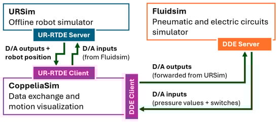
Figure 6.
Simulation programs used and data exchange mechanism between them.
The simulation process is described below:
Initial pressure check:
- (a)
- Set the proportional pressure regulator to 6 bar (fully open);
- (b)
- Open the isolation valve and supply the isolation reservoir with p0 = 4.5 bar;
- (c)
- If the pressure is in range (4.4–4.7 bar), then continue, else stop with a message;
- (d)
- Set the proportional pressure regulator to 0 bar (vent the circuit).
Detecting the pipette:
- (a)
- Set the proportional pressure regulator to 6 bar (fully open);
- (b)
- Open the isolation valve and supply the isolation reservoir with p0 = 4.5 bar;
- (c)
- Close the isolation valve and wait 1 s for the pressure to stabilize;
- (d)
- Open the pipette cylinder control valve, let the pipette cylinder extend for 2 s and then read the pressure from the sensor;
- (e)
- If pressure difference ∆p = p0 − pt ≅ 1.8 bar, then a pipette is detected; if pressure difference ∆p ≅ 2 bar, then the pipette is missing.
Detecting the tip:
- (a)
- Keep the proportional pressure regulator to 6 bar (fully open);
- (b)
- Open the isolation valve and supply the isolation reservoir with p0 = 4.5 bar;
- (c)
- Close the isolation valve and wait 1 s for the pressure to stabilize;
- (d)
- Open the tip cylinder control valve, let the tip cylinder extend for 3 s and then read the pressure from the sensor;
- (e)
- If pressure difference ∆p = p0 − pt ≅ 1.9 bar, then tip is detected; if pressure difference ∆p ≅ 2 bar, then the tip is missing.
Pipetting process:
- (a)
- Tests completed, pipette and tip detected;
- (b)
- Set the proportional pressure regulator to 0 bar (vent the circuit);
- (c)
- Open the Viso and Vc1y valves;
- (d)
- Set the proportional pressure regulator to 3.6 bar, corresponding to a max cylinder force of 25 N, obtaining the full stroke of pipetting button (arm pipette);
- (e)
- Move the robot to the reagent vessel;
- (f)
- Aspire reagent by decreasing pressure to 0 bar for 2 s;
- (g)
- Move the robot to the recipient vessel;
- (h)
- Set the proportional pressure regulator to 2 bar (fast extend until button is touched);
- (i)
- Dispense liquid by increasing the pressure to 3.6 bar for 3 s (for 6 s in a real-world experiment);
- (j)
- Set the proportional pressure regulator to 0 bar = release pipette button;
- (k)
- Close Vc1y and open Vc2y valves;
- (l)
- Set the proportional pressure regulator to 3.6 bar = tip is forced out and discarded and wait 0.5 s;
- (m)
- Set the proportional pressure regulator to 0 bar (vent the circuit) and then close the Vc2y and Viso valves. Process complete.
For better understanding, a video of the entire simulation can be seen here: https://www.youtube.com/watch?v=ip0fxCC7UsU, accessed on 18 March 2025.
2.8. Real-World Experiment
Since in the final application, the pressures will always require some tuning on commissioning, the simplification regarding pre-calculating pressures and volumes is valid, as we do not aim for precise values in advance.
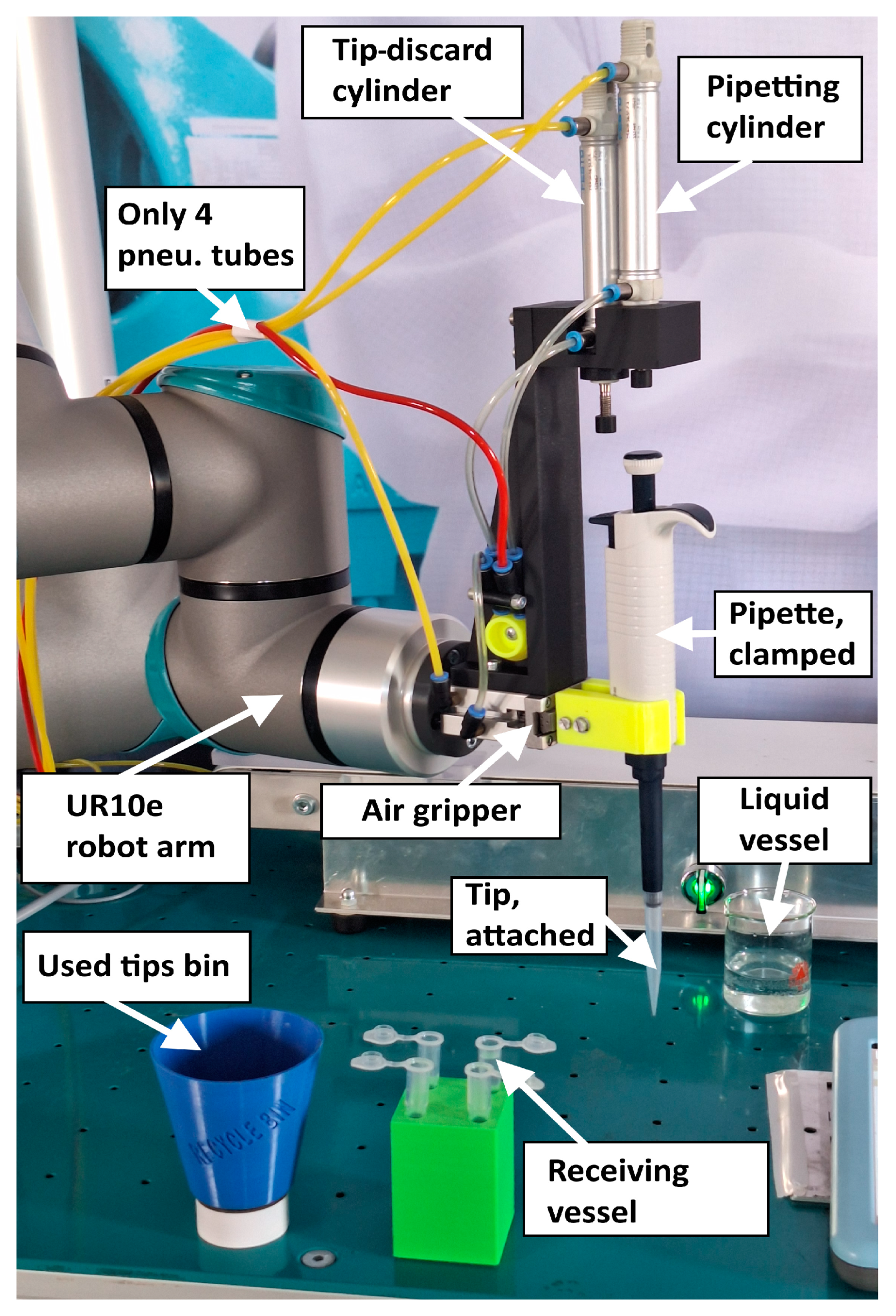
For experimental validation, after connecting all the required components to the robot and setting up its surrounding accessories (bins, vessels, etc.), the same process can be followed as in the simulation, using the electro-pneumatic component types indicated in Section 2.7. The real robot program is slightly adjusted in terms of I/Os, since the pressure sensor will provide the voltage (instead of the current in the simulation). Figure 7 displays the layout of the experimental setup.

Figure 7.
Real-world experimental setup layout—ready for pipetting with liquid.
Two manual switches connected to one of the robot’s digital input ports were used for initiating the testing and pipetting, the same as in the simulation, and the testing was carried out using a pipette with the tip attached, a pipette without a tip and no pipette. Pressure setpoint values were the same as in the simulation.
In order to collect pressure data (we cannot collect the cylinders’ stroke without additional sensory systems), a separate Python v3.11 program was written to connect to the robot via its default Modbus server interface and read pressure sensor values, while testing and pipetting procedures were conducted.
For better understanding, a video of the entire process (repetitive pipette and tip detection testing, dry-run pipetting and actual liquid pipetting) can be seen here: https://www.youtube.com/watch?v=nmcIunfDhCc, accessed on 4 April 2025.
3. Results
Upon launching the simulation with the calculated pressure parameters, what was already expected can be observed, that the pressure limits preset do not give the expected results, in the sense that the available force when isolating the cylinders is lower than expected, leading to the impossibility of accurately detecting the absence of the pipette or tip. Since this is due to various energy losses in the circuit (that are accounted for by Fluidsim), an increase in pressure for both the actuating and isolating branches, as well as for the retraction branch, is needed. Experimental iterative procedure revealed that 4.5 bar on isolation/actuation, with 2.6 bar on retraction, yield the desired results.
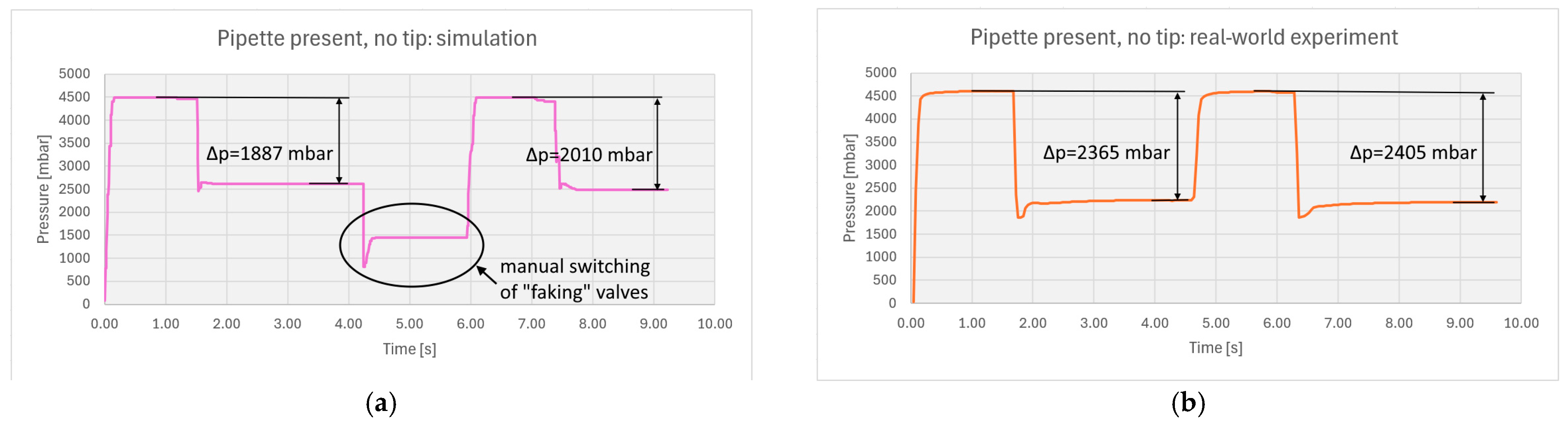
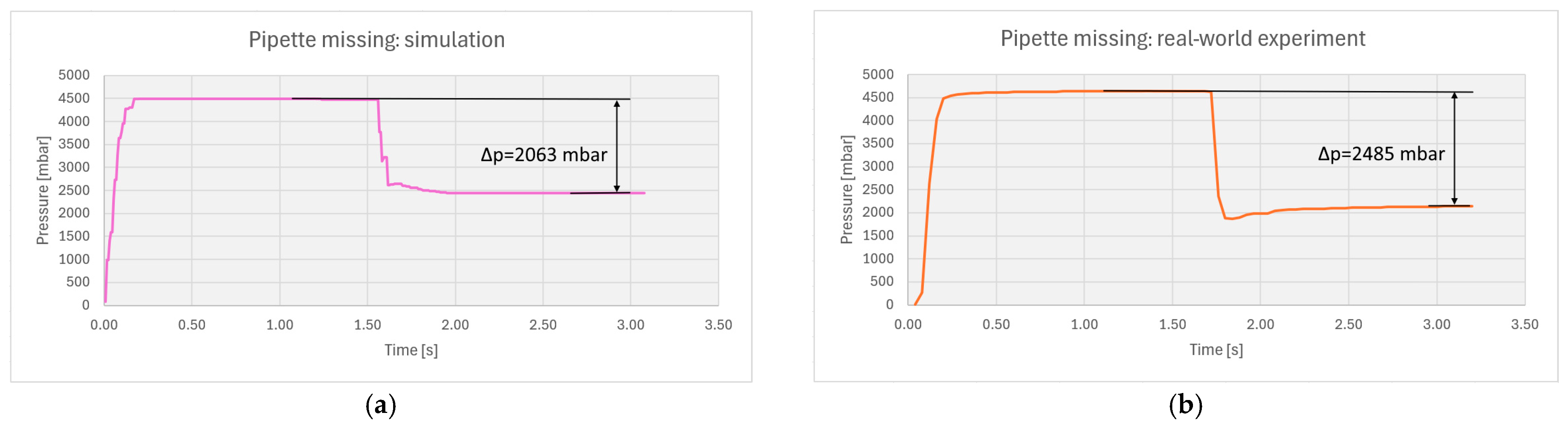
After pressure adjustments, pressure values are collected for the pneumatic remote sensing procedure, which can be observed in Figure 8, Figure 9, Figure 10 and Figure 11, side by side with real-world experimental data. The figures contain data for the pipette’s and tip’s presence (Figure 8a,b), as well as the tip’s absence (Figure 9a,b). The missing pipette is also represented (Figure 10a,b), and a full-process graphical log can also be observed (Figure 11a,b).
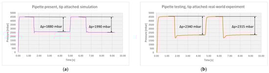
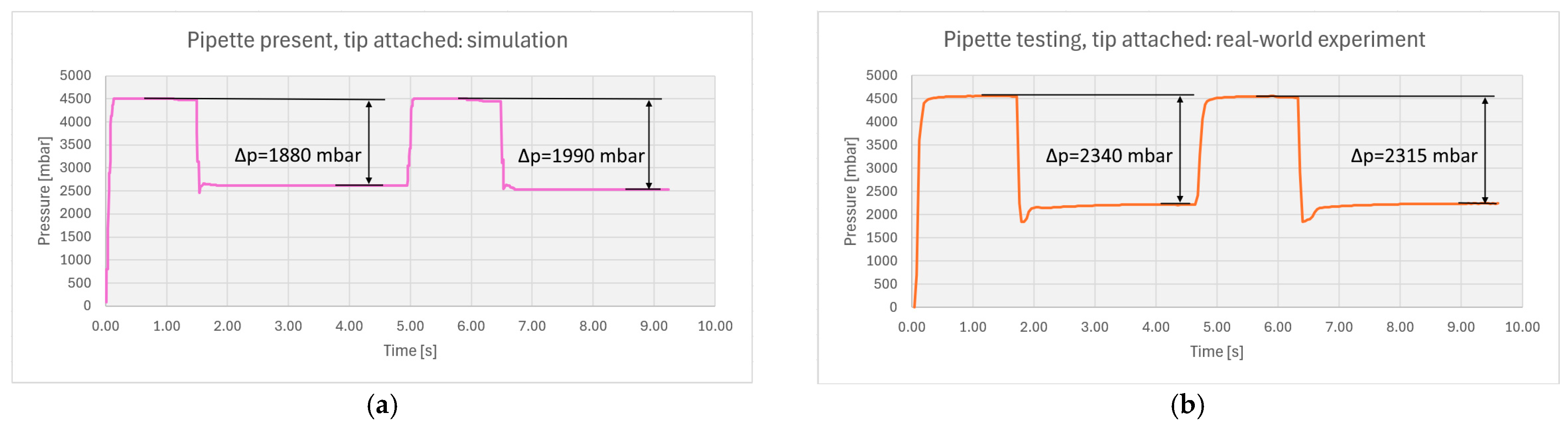
Figure 8.
Detecting the pipette and the tip: (a) simulation; (b) real-world experiment.
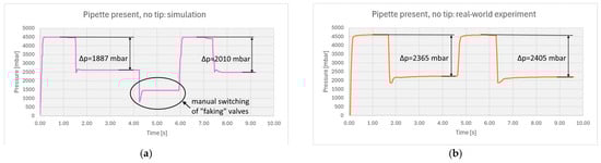
Figure 9.
Detecting the pipette but no tip attached: (a) simulation; (b) real-world experiment.
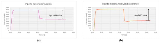
Figure 10.
Not detecting the pipette (tip is not checked): (a) simulation; (b) real-world experiment.
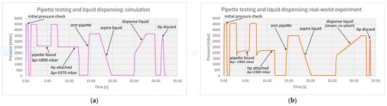
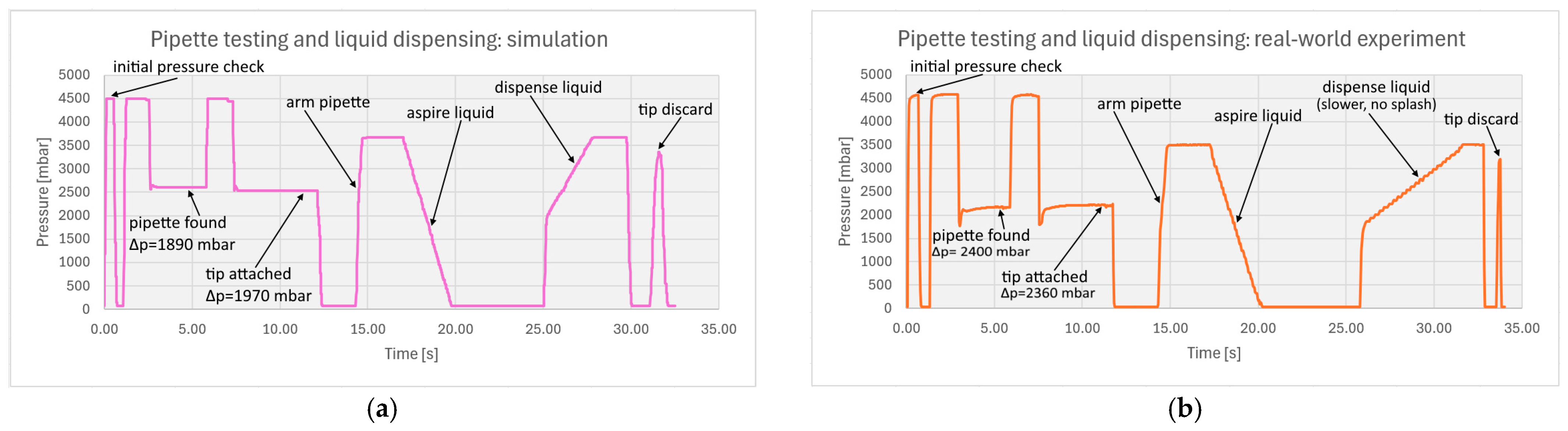
Figure 11.
A complete pipetting cycle—base pressure check, pipette and tip detected, liquid aspired and then dispensed, tip discarded. Zero-pressure time slots between process steps account for robot positioning: (a) simulation; (b) real-world experiment.
From Figure 8a, Figure 9a, Figure 10a and Figure 11a, it can be observed that in simulation the minimum average pressure difference for detecting the pipette is at least 73 mbar, with a total value span of 83 mbar. In real-world experiments, the minimum average pressure difference is at least 85 mbar, with a higher total value span of 145 mbar.
Detecting the tip attachment in simulation can be observed from Figure 8a, Figure 9a and Figure 11a, with a minimum average pressure difference of at least 20 mbar and a total span of 50 mbar. In real-world experiments (Figure 8b, Figure 9b and Figure 11b), the minimum average pressure difference is at least 45 mbar, with a total span of 90 mbar.
Pipetting (liquid dispensing) can be observed in the second part of Figure 11a,b (after testing, t > 12 s), followed by tip discarding. For these actuations the pressure was limited (with the proportional pressure regulator) to 3.6 bar, to restricting the cylinders’ pushing forces at 25 N.
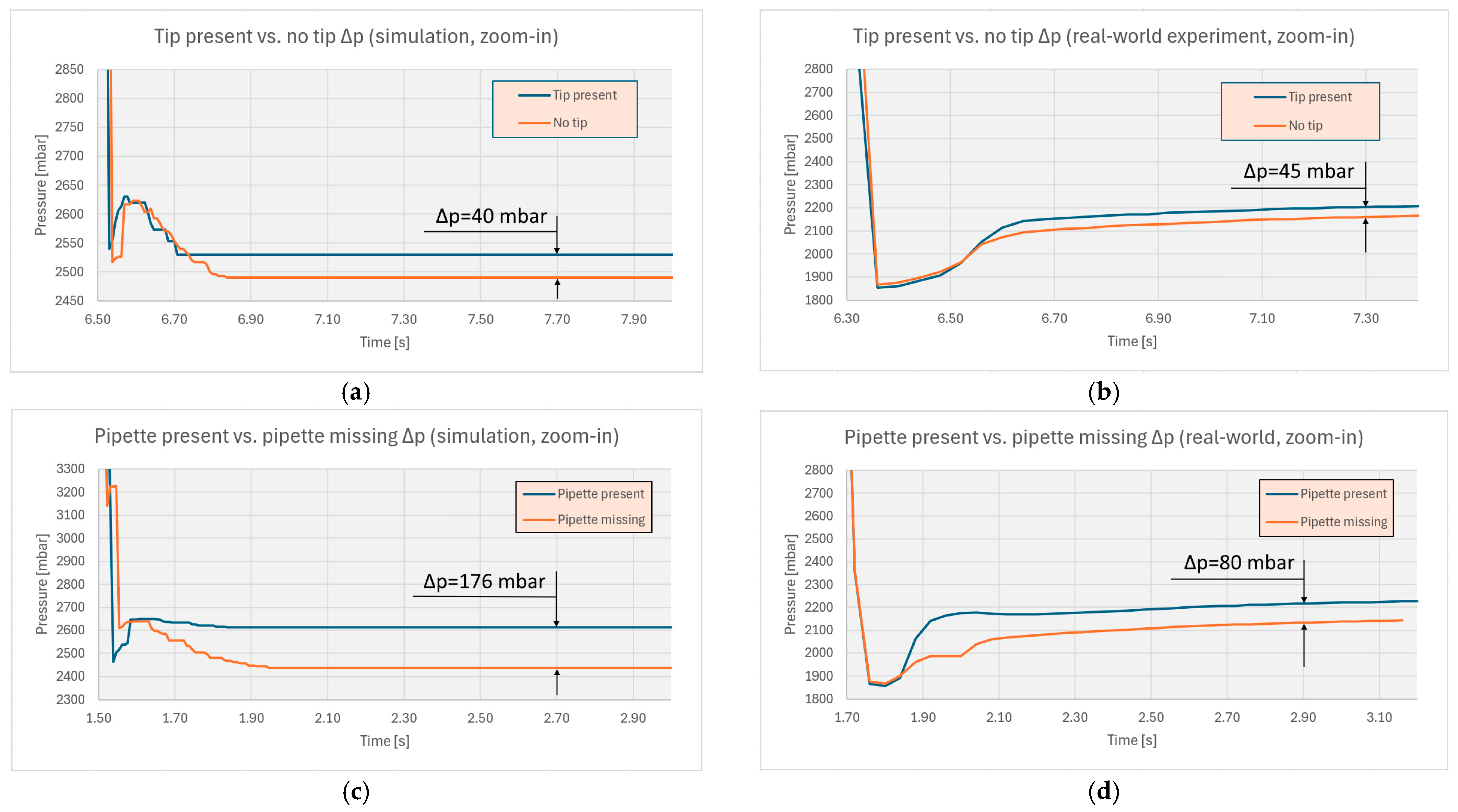
Figure 12 shows relative pressure differences points (lowest differences) for tip detecting in simulation (Figure 12a), tip detecting in real-life experiments (Figure 12b), pipette detecting in simulation (Figure 12c) and pipette detecting in real-world experiments (Figure 12d).
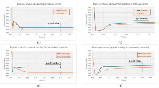
Figure 12.
Relative pressure differences for tip detecting in simulation (a), and in real-world experiments (b), and pipette detecting in simulation (c) and in real-world experiments (d).
The values collected [S4] are well within the pressure sensor limits and robot’s analog to digital converter limits, so the data can be trusted, and the detection limits can be used with little overhead (20 mbar) in the robot’s program.
4. Discussion
As stated and expected, the initial simple pressure calculations are not directly suitable for use in a simulation or in real-world experiments and require adjustments (an increase) in order to compensate for unaccounted for losses in the mechanics and in the pneumatic circuits. For the simulation, the iterative process is fast, the required pressure setpoints being found after only three adjusting steps. This is also facilitated by the working pressures/forces intervals of interest, which are relatively permissive (an 100 mbar deviation in pressure setpoints does affect the results’ values but not the possibility of pipette/tip presence identification). For real-world experiments, the pressures’ setting values from the simulation proved to be appropriate, and the detection was correct on all test runs.
4.1. Results Analysis
Analyzing the results presented in Figure 8, Figure 9, Figure 10 and Figure 11, several aspects must be noted.
4.1.1. For Remote Sensing in Simulation
Detecting the presence of the pipette (stopping the cylinder due to the imposed force profile) is consistent over many test runs.
Detecting the attachment of the tip (stopping the cylinder due to the imposed force profile) is consistent over many test runs.
Detecting the missing pipette or the missing tip (full stroke of the cylinders) is also consistent over all test runs.
The variance in the pressure at the measuring points for all testing types (with pipette and tip present) is less than 20 mbar, and thus it does not affect detection.
4.1.2. For Remote Sensing in Experiments
Detecting the presence of the pipette is consistent over all test runs. No false detection occurred.
Detecting the attachment of the tip is consistent over all test runs. False detection of the tip can occur if the supply pressure is slightly modified. As a mitigation strategy, an electronic pressure regulator could also be used for the main air supply, instead of the less precise manual one (with manometer eyeballing).
Detecting the missing pipette is also consistent over all test runs. No false detection occurred.
The variance in the pressure at the measuring points for all testing types (with pipette and tip present) is less than 60 mbar, not affecting detection, but careful supply pressure setting must be ensured.
4.1.3. For Pipetting and Tip Discarding in Simulation
The robot commands the release of pressure from the pipetting cylinder (during reagent collection) in a linear stepped fashion during a program loop (250 mbar, every 0.1 s, from 6 bar to 0 bar). The resulting piston rod position over time is non-linear in its return. This aspect needs further investigation, and it must be decided if modifying the pressure release curve for position linearization is mandatory for collecting the correct amount of reagent. For the pipetting (and last droplet expel) action, there is also a program loop that increases the pressure in a stepped linear way (250 mbar, every 0.1 s, from 2 bar to 6 bar). The piston rod position is, again, non-linear over time, and again this needs further investigation to ensure that all the liquid content, including the last droplet, is correctly deposited in the recipient tube.
4.1.4. For Pipetting and Tip Discarding in Real-World Experiments
Since the cylinders’ position/buttons are not recorded, only a subjective qualitative impression can be presented: the pipetting process looks normal, both for reagent collection and for reagent pipetting/droplet expelling, for all test runs. One aspect must be noted: since the receiving liquid vessel is of a small volume (approx. 1.5 mL), dispensing from the pipette too fast will make the liquid splash out of the vessel. To mitigate this, the dispensing time was enlarged in the robot program, reaching 6 s. Tip discarding happens fast, and the tip dropped in the discarding bin for all test runs.
No abnormal pipette movement/displacement was observed during actuation (but some small motion can be noticed, especially at higher forces/max. strokes). The pipette remained firmly gripped, in the correct position, for the entire process, for all test runs.
To verify the ease of pneumatic installation to the robot’s end effector (gripper and cylinders), several colleagues were asked to connect the tubes, at first sight, without a prior introduction. Since the tube ends and actuators ports are labeled, the task was completed in less than a minute and correctly so, every time. This also proves the validity of the simple pneumatic-only end effector concept, making it suitable, for example, for frequent dismantling, cleaning and reassembly by targeted lab technicians.
4.2. Regarding the Use of Different Pipette Types
If the system is to be used with different pipette models/types, this requires some adaptations in the mechanical design of the gripper fingers’/cylinder’s position, as well as in the pneumatics selection. For the actuating cylinders, this mainly refers to the selection of their stroke (although manual pipettes should have similar buttons’ strokes and forces). The pressure control algorithm must also be adapted for each pipette model/type. As presented, the system is designed to work with fixed (or rigid adjusted) known-volume pipettes = known strokes.
4.3. Pneumatics Service Life Estimation and Maintenance Strategy
Usually, industrial pneumatic components have a durability of tens of years, when used with clean compressed air and subjected to a fraction of their maximum performance (pressure, actuating forces, radial rod loading, etc.). Piloted pneumatic valves have a switching life exceeding 10 × 106 cycles, while direct actuated valves (the type used in this paper) are rated for 5 × 10⁸ cycles [47]. For cylinders, a stroke run value of at least 8000 km can be considered [48], which in our case is equivalent to 8 × 10⁶ cycles. The estimated actuating cycles (valve or cylinder) for this application are 1 cycle/5 s, 16 h/day, 300 days/year = 3.45 million cycles/year, giving an estimated service life of more than 10 years for the pneumatic components.
Maintenance strategy: Preventive maintenance should be scheduled once a year and outsourced to a specialized company. The maintenance process should test for positive pressure leaks in the valves and cylinders while installed in the system. The proportional pressure valve should be stepped from 0 to 4.5 bar with 0.1 bar increments and pressure sensor values analyzed. A separate cycle counter can also be defined as a retentive variable in the robot, and a program function can alert the technicians at 10 million cycles to schedule a supplementary thorough maintenance.
4.4. Further Research
The need for pipetting cylinder rod position linearization and complete process simulation and experimentation (pipette acquiring, testing, multiple pipetting and tip-discarding actions, pipette re-depositing, pipette changing with one of a different volume, etc.) was identified. Also, the cycle time for a complete sample preparation must be obtained and optimized, in terms of robot workspace, robot trajectories and minimum allowable waiting times during pneumatic sensing and actuation (in this work, fixed wait times were used).
Another aspect that deserves attention is redesigning the complete end effector for a more compact appearance. This involves changing the cylinders’ position with respect to the pipette/gripper and finding an optimal buttons’ actuation mechanism. Pressures levels will also need to be adapted.
Finally, assessing the performance of the end effector in high- and low-temperature environments and also in high-interference environments should be conducted to further validate this remote pneumatic sensing solution.
5. Conclusions
Robotized reagent collection, pipetting and pipette tip discarding can be successfully conducted using pneumatic actuation of a manual microliter pipette.
Remote pneumatic sensing is suitable for the detection of the presence/absence of the pipette and for the detection of an attached tip.
Functional simulation of the actuating and sensing process can be achieved with a high degree of accuracy by using a combination of dedicated software tools for the pneumatic and robotic parts, and a middleware (linking) program must be used to facilitate the data exchange.
Real-world experiments give accurate results for all the test runs, confirming the initial hypothesis. Also, the ease of connecting/disconnecting the pneumatic tubing is confirmed by using untrained people and obtaining correct connections every time.
The proposed actuation/sensing method can be successfully used in biochemistry samples’ unattended preparation, provided a simple and flexible robotic solution is preferred.
Supplementary Materials
The following supporting information can be downloaded at: https://www.mdpi.com/article/10.3390/machines13050389/s1, File S1: Robot program from URSim v5.14; File S2: Simulation scene from Coppelaisim v4.9; File S3: Electro-pneumatic circuit diagram from Fluidsim v5; File S4: Recorded values tables.
Author Contributions
Conceptualization, V.C. and E.-C.L.; methodology, V.C.; software, V.C. and R.K.; validation, E.-C.L., C.S. and V.C.; formal analysis, M.-O.S.; investigation, M.-O.S. and V.C.; resources, M.-O.S. and R.K.; data curation, R.K.; writing—original draft preparation, V.C.; writing—review and editing, E.-C.L.; visualization, C.S.; supervision, V.C. All authors have read and agreed to the published version of the manuscript.
Funding
This research received no external funding.
Data Availability Statement
Data available in the Supplementary Materials.
Conflicts of Interest
The authors declare no conflicts of interest.
References
- Bjőrkstén, M.G.; Aimby, B.; Jansson, E.S. Hand and shoulder ailments among laboratory technicians using modern plunger-operated pipettes. Appl. Ergon. 1994, 25, 88–94. [Google Scholar] [CrossRef] [PubMed]
- Enuh, B.M. AZO Robotics Editorial—Robots in the Lab: Automated Pipetting. Available online: https://www.azorobotics.com/Article.aspx?ArticleID=562 (accessed on 31 March 2025).
- Bass, J. News Medical Life Sciences Editorial: Productive Pipetting—Are Robots the Solution? Available online: https://www.news-medical.net/news/20150203/Productive-Pipetting-are-robots-the-only-solution-An-interview-with-Juerg-Bass-Integra-Biosciences.aspx (accessed on 31 March 2025).
- Lê, N. Dispendix Editorial—The Impact of Robotic Pipetting on Lab Practices. Available online: https://dispendix.com/blog/the-impact-of-robotic-pipetting-on-lab-practices (accessed on 31 March 2025).
- SPT LabTech—Apricot Liquid Handling Instruments. Available online: https://www.sptlabtech.com/products/apricot (accessed on 31 March 2025).
- Hudson Lab Automation—Automated Liquid Handlers. Available online: https://hudsonlabautomation.com/products/liquid-handlers/ (accessed on 31 March 2025).
- Mettler Toledo—Rainin MicroPro Pipettor. Available online: https://www.mt.com/gb/en/home/products/pipettes/high-throughput-platforms/micropro-benchtop-pipettor.html (accessed on 31 March 2025).
- Zhao, X.; Yuan, Z.; Lin, L.; Zheng, C.; You, H. Development of a New Lightweight Multi-Channel Micro-Pipette Device. Machines 2024, 12, 359. [Google Scholar] [CrossRef]
- Faiña, A.; Nejati, B.; Stoy, K. EvoBot: An Open-Source, Modular, Liquid Handling Robot for Scientific Experiments. Appl. Sci. 2020, 10, 814. [Google Scholar] [CrossRef]
- Rybak, L.; Carbone, G.; Malyshev, D.; Voloshkin, A. Design and Optimization of a Robot Dosing Device for Aliquoting of Biological Samples Based on Genetic Algorithms. Machines 2024, 12, 172. [Google Scholar] [CrossRef]
- Fleischer, H.; Baumann, D.; Joshi, S.; Chu, X.; Roddelkopf, T.; Klos, M.; Thurow, K. Analytical Measurements and Efficient Process Generation Using a Dual–Arm Robot Equipped with Electronic Pipettes. Energies 2018, 11, 2567. [Google Scholar] [CrossRef]
- Azuma, T.; Matsunaga, N.; Ohmagari, N.; Kuroda, M. Development of a High-Throughput Analytical Method for Antimicrobials in Wastewater Using an Automated Pipetting and Solid-Phase Extraction System. Antibiotics 2024, 13, 335. [Google Scholar] [CrossRef]
- Andrew Alliance—Andrew Pipetting Robot. Available online: https://www.andrewalliance.com/pipetting-robot/ (accessed on 31 March 2025).
- Sandu, M.-O.; Ciupe, V.; Gruescu, C.-M.; Kristof, R.; Sticlaru, C.; Tulcan, E.-G. Determining the Proper Force Parameters for Robotized Pipetting Devices Used in Automated Polymerase Chain Reaction (PCR). Robotics 2025, 14, 2. [Google Scholar] [CrossRef]
- Zhang, J.; Wan, W.; Tanaka, N.; Fujita, M.; Takahashi, K.; Harada, K. Integrating a Pipette Into a Robot Manipulator With Uncalibrated Vision and TCP for Liquid Handling. IEEE Trans. Autom. Sci. Eng. 2024, 21, 5503–5522. [Google Scholar] [CrossRef]
- Yoshikawa, N.; Garg, A.; Darvish, K.; Vakili, M.G.; Aspuru-Guzik, A. Digital pipette: Open hardware for liquid transfer in self-driving laboratories. Digit. Discov. 2023, 2, 1745–1751. [Google Scholar] [CrossRef]
- Tatsumi, N.; Okuda, K.; Tsuda, I. A new direction in automated laboratory testing in Japan: Five years of experience with total laboratory automation system management. Clin. Chim. Acta 1999, 290, 93–108. [Google Scholar] [CrossRef]
- Florian, D.C.; Odziomek, M.; Ock1, C.L.; Chen, H.; Guelcher, S.A. Principles of computer controlled linear motion applied to an open source afordable liquid handler for automated micropipetting. Sci. Rep. 2020, 10, 13663. [Google Scholar] [CrossRef] [PubMed]
- Navas-Reascos, G.E.; Romero, D.; Rodriguez, C.A.; Guedea, F.; Stahre, J. Wire Harness Assembly Process Supported by a Collaborative Robot: A Case Study Focus on Ergonomics. Robotics 2022, 11, 131. [Google Scholar] [CrossRef]
- Malobický, B.; Hruboš, M.; Kafková, J.; Krško, J.; Michálik, M.; Pirník, R.; Kuchár, P. Towards Seamless Human–Robot Interaction: Integrating Computer Vision for Tool Handover and Gesture-Based Control. Appl. Sci. 2025, 15, 3575. [Google Scholar] [CrossRef]
- Witeg—Witopet Microliter Pipettes Fix Single-Channel. Available online: https://www.witeg.de/en/microliter-pipettes-witopet-economy-fix-single-channel/5-401-910 (accessed on 31 March 2025).
- Pololu—RC Servos. Available online: https://www.pololu.com/category/23/rc-servos (accessed on 31 March 2025).
- Qiu, Z.; Shimizu, M.; Wang, Z.; Kawamura, S. A Position Estimation Method for Pneumatic Actuators Based on Flow and Pressure Sensors. IEEE Trans. Instrum. Meas. 2024, 73, 7509209. [Google Scholar] [CrossRef]
- Youssry, M.A.; Elmayyah, W.M.; Mabrouk, M.H. Position control of a pneumatic cylinder actuator using modified PWM algorithm. Eng. Sci. Mil. Technol. 2020, 4, 121–126. [Google Scholar] [CrossRef]
- Dhavalikar, M.; Dingare, S.; Patle, B. A review of pneumatic cylinder positioning techniques for high positioning accuracy and minimal response time. Mater. Today Proc. 2023, 72, 1590–1595. [Google Scholar] [CrossRef]
- Zhu, H.; Wang, Z.; Wang, H.; Zhao, Z.; Xiong, W. Leakage Fault Diagnosis of Two Parallel Cylinders in Pneumatic System with a Minimal Number of Sensors. Electronics 2023, 12, 3261. [Google Scholar] [CrossRef]
- Krause, J.; Bhounsule, P. A 3D Printed Linear Pneumatic Actuator for Position, Force and Impedance Control. Actuators 2018, 7, 24. [Google Scholar] [CrossRef]
- Rouzbeh, B.; Bone, G.M. Optimal Force Allocation and Position Control of Hybrid Pneumatic–Electric Linear Actuators. Actuators 2020, 9, 86. [Google Scholar] [CrossRef]
- Falcão Carneiro, J.; Bravo Pinto, J.; Gomes de Almeida, F. Accurate Motion Control of a Pneumatic Linear Peristaltic Actuator. Actuators 2020, 9, 63. [Google Scholar] [CrossRef]
- Pei, G.; Yu, M.; Xu, Y.; Ma, C.; Lai, H.; Chen, F.; Lin, H. An Improved PID Controller for the Compliant Constant-Force Actuator Based on BP Neural Network and Smith Predictor. Appl. Sci. 2021, 11, 2685. [Google Scholar] [CrossRef]
- Rohmer, E.; Singh, S.P.N.; Freese, M. CoppeliaSim (formerly V-REP): A Versatile and Scalable Robot Simulation Framework. In Proceedings of the 2013 IEEE/RSJ International Conference on Intelligent Robots and Systems, Tokyo, Japan, 3–7 November 2013; Available online: https://www.coppeliarobotics.com/ (accessed on 31 March 2025).
- Montenegro, G.; Chacón, R.; Fabregas, E.; Garcia, G.; Schröder, K.; Marroquín, A.; Dormido-Canto, S.; Farias, G. Modeling and Control of a Spherical Robot in the CoppeliaSim Simulator. Sensors 2022, 22, 6020. [Google Scholar] [CrossRef] [PubMed]
- Yoon, J.; Son, B.; Lee, D. Comparative Study of Physics Engines for Robot Simulation with Mechanical Interaction. Appl. Sci. 2023, 13, 680. [Google Scholar] [CrossRef]
- Zhang, X.; Chen, L.; Dong, W.; Li, C. Optimizing Redundant Robot Kinematics and Motion Planning via Advanced D-H Analysis and Enhanced Artificial Potential Fields. Electronics 2024, 13, 3304. [Google Scholar] [CrossRef]
- Art Systems—Fluidsim v5. Available online: https://www.art-systems.de/www/site/en/downloads/fluidsim5.html (accessed on 31 March 2025).
- Szcześniak, A.; Szcześniak, Z. Algorithmic Method for the Design of Sequential Circuits with the Use of Logic Elements. Appl. Sci. 2021, 11, 11100. [Google Scholar] [CrossRef]
- Universal Robots—URSIM for Non-Linux Offline Simulator. Available online: https://www.universal-robots.com/download/software-ur20ur30/simulator-non-linux/offline-simulator-e-series-and-ur20ur30-ur-sim-for-non-linux-5213/ (accessed on 31 March 2025).
- Universal Robots—Cobots and Software. Available online: https://www.universal-robots.com/products/ (accessed on 31 March 2025).
- Festo—Round Cylinders. Available online: https://www.festo.com/us/en/e/festo-round-cylinders-dsnu-s-and-dsnu-id_933415/ (accessed on 31 March 2025).
- SMC—Standard Air Cylinders (Round Type). Available online: https://www.smcworld.com/webcatalog/en-jp/air-cylinders/air-cylinders-round-type/CJ2-X3175-E (accessed on 31 March 2025).
- Witeg—Microliter Pipette User Manual. Available online: https://www.witeg.de/daten/manuals/WITOPETeconomy_DE.pdf (accessed on 31 March 2025).
- Festo—ISO Cylinder DSNUP-16-50-P-A. Available online: https://ftp.festo.com/public/PNEUMATIC/SOFTWARE_SERVICE/DataSheet/EN_GB/551669.pdf (accessed on 31 March 2025).
- Festo—Proportional Pressure Control Valve VEAB. Available online: https://www.festo.com/media/catalog/205224_documentation.pdf (accessed on 31 March 2025).
- Universal Robots—UR10e User Manual. Available online: https://www.universal-robots.com/download/manuals-e-seriesur20ur30/user/ur10e/521/user-manual-ur10e-e-series-sw-521-english-international-en/ (accessed on 31 March 2025).
- Microsoft—About Dynamic Data Exchange. Available online: https://learn.microsoft.com/en-us/windows/win32/dataxchg/about-dynamic-data-exchange (accessed on 31 March 2025).
- PyPI—Project ur-rtde v1.6.0. Available online: https://pypi.org/project/ur-rtde/ (accessed on 31 March 2025).
- Festo—Solenoid Fast Switching Valves. Available online: https://www.festo.com/media/catalog/203293_documentation.pdf (accessed on 31 March 2025).
- SMC—Product Selection Guide. Available online: https://www.smcworld.com/products/select_guide/en-jp/actuator/aircylinder_data.html (accessed on 31 March 2025).

Disclaimer/Publisher’s Note: The statements, opinions and data contained in all publications are solely those of the individual author(s) and contributor(s) and not of MDPI and/or the editor(s). MDPI and/or the editor(s) disclaim responsibility for any injury to people or property resulting from any ideas, methods, instructions or products referred to in the content. |
© 2025 by the authors. Licensee MDPI, Basel, Switzerland. This article is an open access article distributed under the terms and conditions of the Creative Commons Attribution (CC BY) license (https://creativecommons.org/licenses/by/4.0/).