In order to explore the influence of various structural parameters on the electromagnetic performance of PMVMs, PMVMs with different shapes of FMPs, different numbers of FMPs, and different slot–pole combinations are compared in this section, and changing laws of the performance of PMVMs with different topologies and structural parameters are obtained. All models in this article are built by using ANSYS Maxwell 2022R2 software, and the finite element analysis method (FEM) is used to compare the electromagnetic performance of all PMVMs and PMSMs.
2.1. Comparison of Different Shapes of FMPs
When exploring the effects of the pole slot combination, number of permanent magnet poles, and electromagnetic reduction ratio on the electromagnetic performance of a PMVM, it is first necessary to select a suitable shape for the modulation teeth (FMPs) of the PMVMs to avoid the disadvantage of slot type of FMPs on performance analysis.
Therefore, this section takes 12-slot/18-FMP/13-pole-pair PMVMs as the research object to study the influence of different shapes of FMPs on the comprehensive performance of the motor.
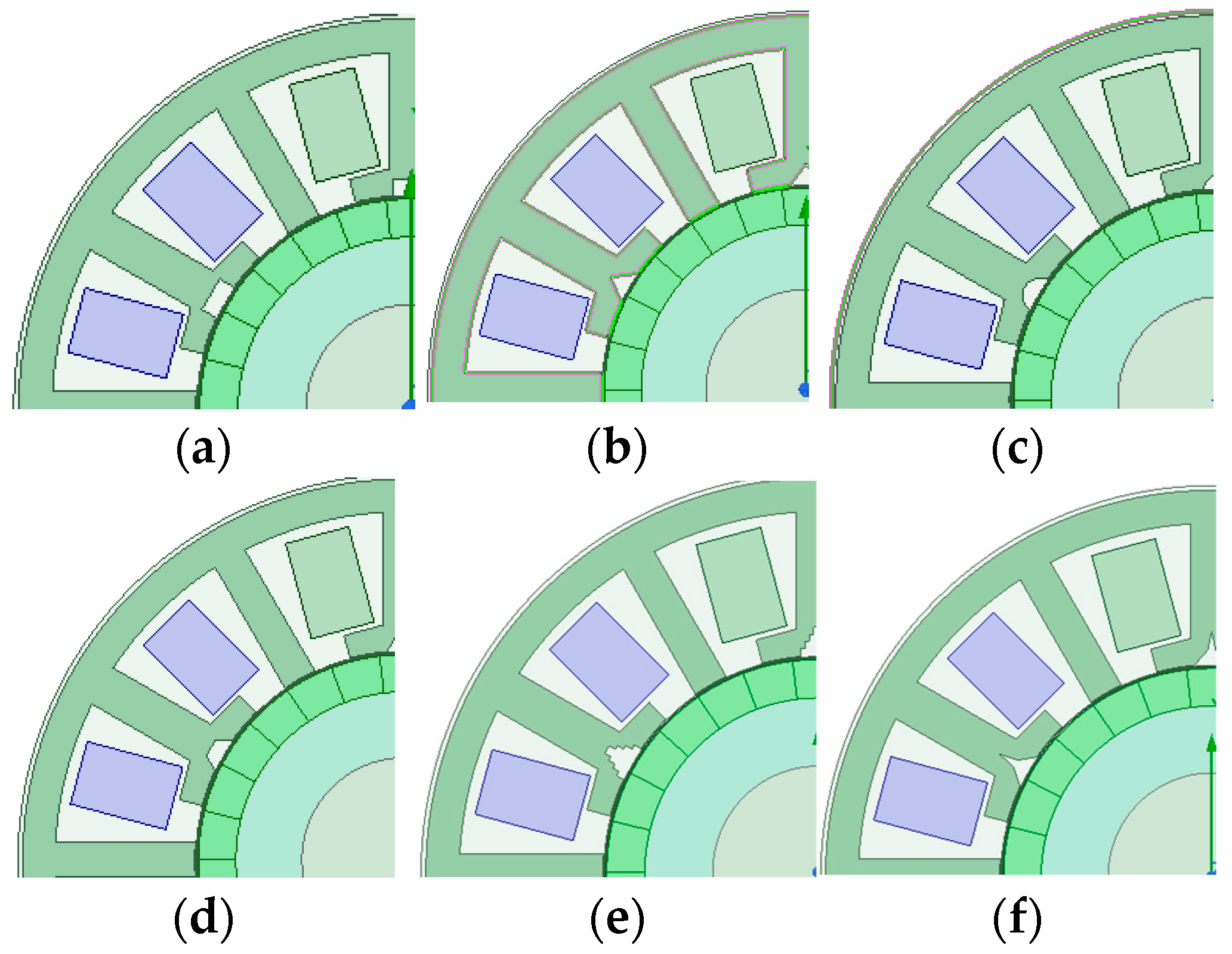
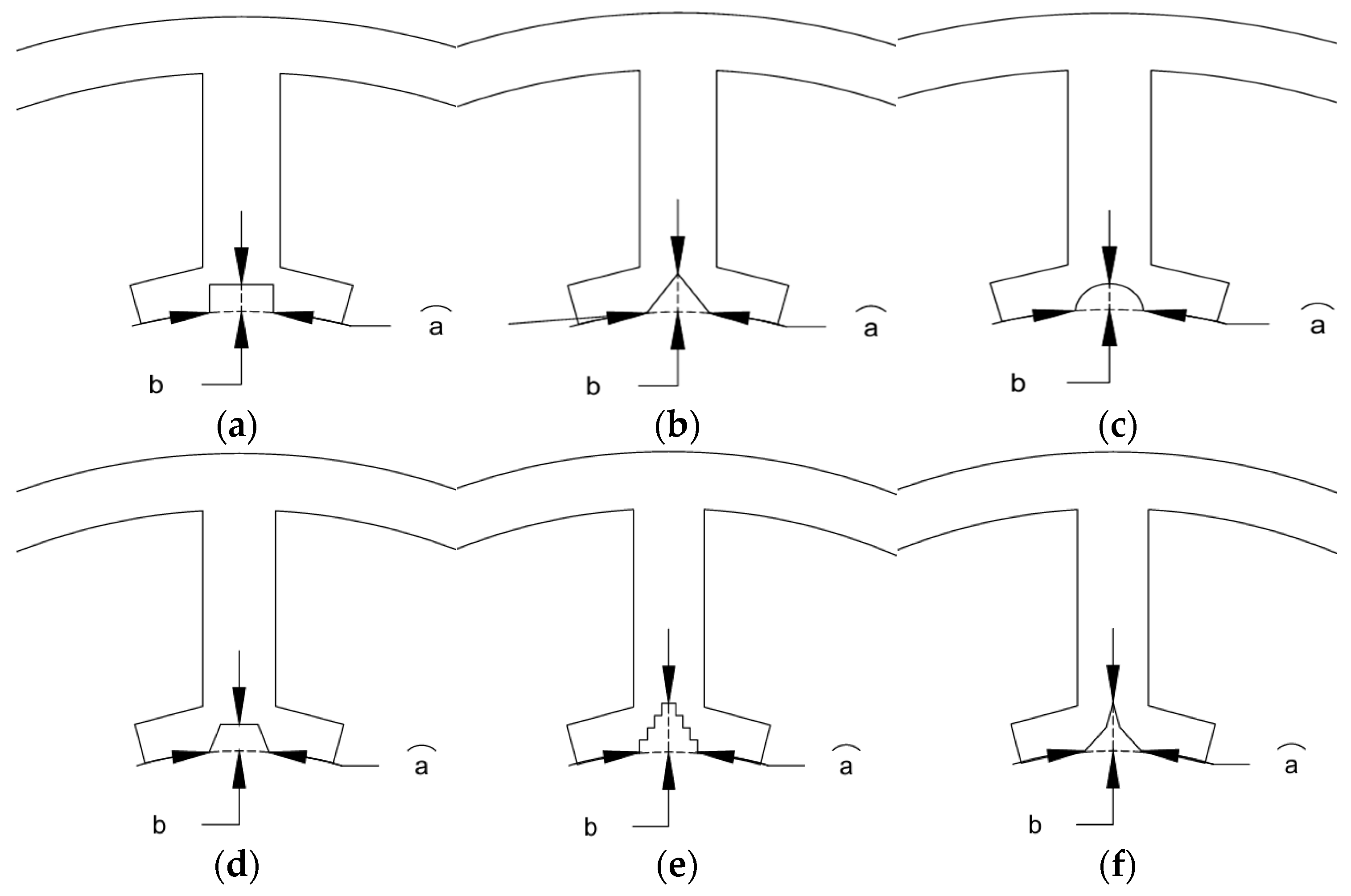
Different shapes of FMPs are shown in
Figure 1. In order to accurately evaluate the differences in the magnetic field modulation ability of different topologies, different stator topologies of PMVMs are kept with the same cross-sectional area of the stator core to explore the performance differences in PMVMs with different FMP shapes while ensuring consistent structural parameters and the same amount of silicon steel material. The common structural parameters of PMVMs are shown in
Table 1.
The no-load characteristics of PMVMs with six different FMP structures are studied separately, as shown in
Figure 2 and
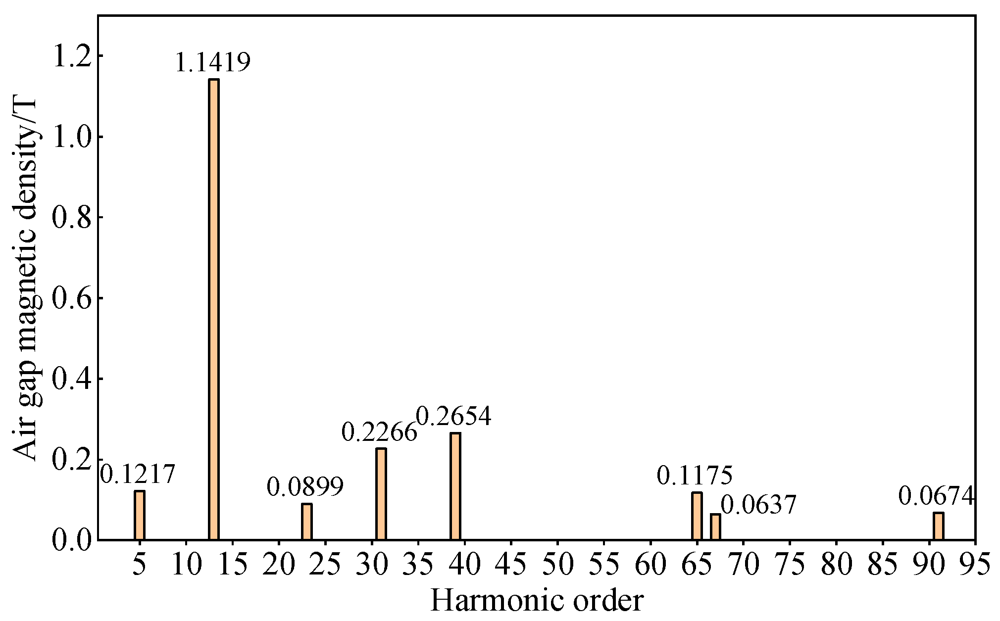
Figure 3. Keeping the motor speed at 500 rpm, it is found that the no-load back EMF amplitude of PMVMs with five special tooth structures is greater than that of PMVMs with conventional tooth structures. The no-load back EMF amplitude of PMVMs with triangular teeth is the largest. At the same time, from the Fourier decomposition results of the no-load air gap magnetic density, the main harmonic orders contained in the six different PMVMs remain the same, but the amplitudes of the main harmonics are different. After conducting a comparison, it is found that the 5th harmonic, 13th harmonic, 23rd harmonic, 31st harmonic, and 39th harmonic of PMVMs with triangular teeth have significant advantages over conventional PMVMs. As shown in
Figure 3, although the fundamental harmonic amplitude of PMVMs with tower-shaped teeth and PMVMs with trapezoidal teeth is higher than that of conventional PMVMs, their other low-order modulation harmonics do not have advantages. Therefore, the triangular tooth-shaped PMVM has best magnetic field modulation ability.
The magnetic flux density distribution of different kinds of FMPs of the PMVMs is analyzed under rated conditions, as shown in
Figure 4, it can be found that PMVMs with conventional tooth structures are very prone to the saturation of the yoke of modulation teeth, which causes a large amount of magnetic leakage in the stator teeth and greatly limits the improvement in and optimization of torque density. Under the same conditions, the saturation degree of the triangular tooth structure and the tower-shaped structure is smaller, and the magnetic density distribution is more uniform compared to the PMVMs with conventional tooth structures, which is conducive to an improvement in torque density.
In addition, based on the previous research results, it can be concluded that the order and quantity of modulation harmonics are determined by the number of FMPs of PMVMs, the number of permanent magnet poles, and the electromagnetic reduction ratio. Different shapes of FMPs can change the amplitude of each order harmonic, which is of great help in improving the torque capability of PMVMs.
In order to verify the correctness of the air gap magnetic density Fourier decomposition and magnetic flux density distribution results and more accurately evaluate the electromagnetic performance of PMVMs with different types of FMPs, parameterized modeling is carried out on the stator teeth of these six PMVMs. The parameterized variables of PMVMs with different shapes of FMPs are shown in
Figure 5, and the value ranges of different variables are shown in
Table 2. While all other structural parameters maintain their original proportions or remain unchanged, 50 parameter combinations are selected by using the symmetric reverse equidistant parameter scanning method within the range of
Table 2 values, and their torque and torque fluctuations are analyzed separately. The results are shown in
Figure 6. It can be found that the torque ranges of PMVMs with triangular teeth, PMVMs with circular teeth and PMVMs with trapezoidal teeth have certain advantages compared to traditional PMVMs, and the advantage of PMVMs with triangular teeth is the most obvious, which verifies the correctness of the previous analysis.
2.2. Comparison of Different Slot–Pole Combinations of PMVMs
In this section, the number of slots for the motors are set to 6 or 12, respectively, which is used to explore the electromagnetic performance of the PMVMs under different combinations of slot numbers and permanent magnet pole numbers. All FMP shapes of motors are set to triangles. By comparing the no-load back EMF, torque, and overload capacity of different PMVM topologies, the changing law of motor performance with the number of FMPs under different slot numbers is obtained.
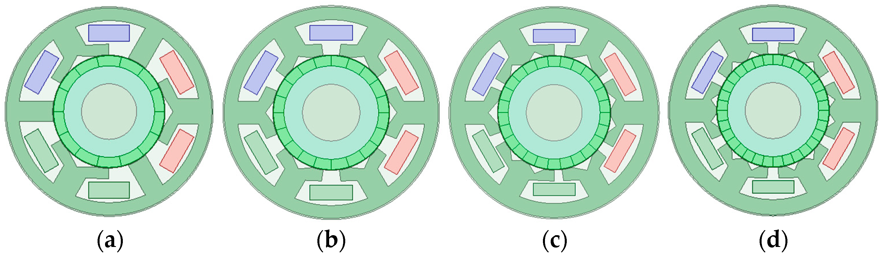
For six-slot motors, all motor topologies are shown in
Figure 7 below.
is defined as the electromagnetic reduction ratio of a motor, which is equal to the ratio of the number of permanent magnet poles to the number of stator winding poles. When the number of slots in the motor is six, the number of FMPs on each tooth gradually increases, resulting in multiple slot–pole combinations, as seen in
Table 3. A1 in
Table 3 corresponds to
Figure 6a, A2 in
Table 3 corresponds to
Figure 6b, A3 in
Table 3 corresponds to
Figure 6c, A4 in
Table 3 corresponds to
Figure 6d, and A1–A4 corresponds to four six-slot PMVM topologies in
Figure 7. While keeping the number of armature winding pole-pairs constant, the total number of FMPs gradually increases. At this time, the number of permanent magnet pole pairs and electromagnetic deceleration ratio of the PMVM also gradually increase.
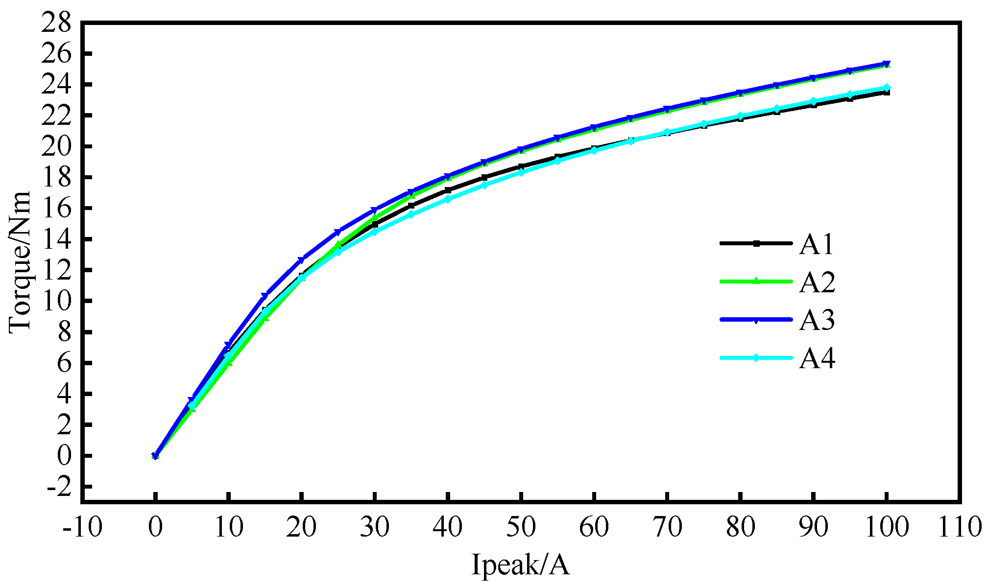
These six-slot PMVMs have the same structural parameters except for the number of FMPs on the stator and the number of permanent magnets on the rotor. The outer diameter of the stator for all topologies remains 82 mm, and they are all in the form of a single-layer concentrated winding structure. In order to explore the changes in the electromagnetic properties of the motors under different slot–pole combinations, the back EMF, air gap flux density, and torque of different kinds of PMVMs are analyzed under the no-load condition and load current amplitudes of 50 A. The variation in torque with current is also analyzed. To verify the fault tolerance of the single-layer concentrated winding structure, self-inductance and mutual inductance are analyzed, too.
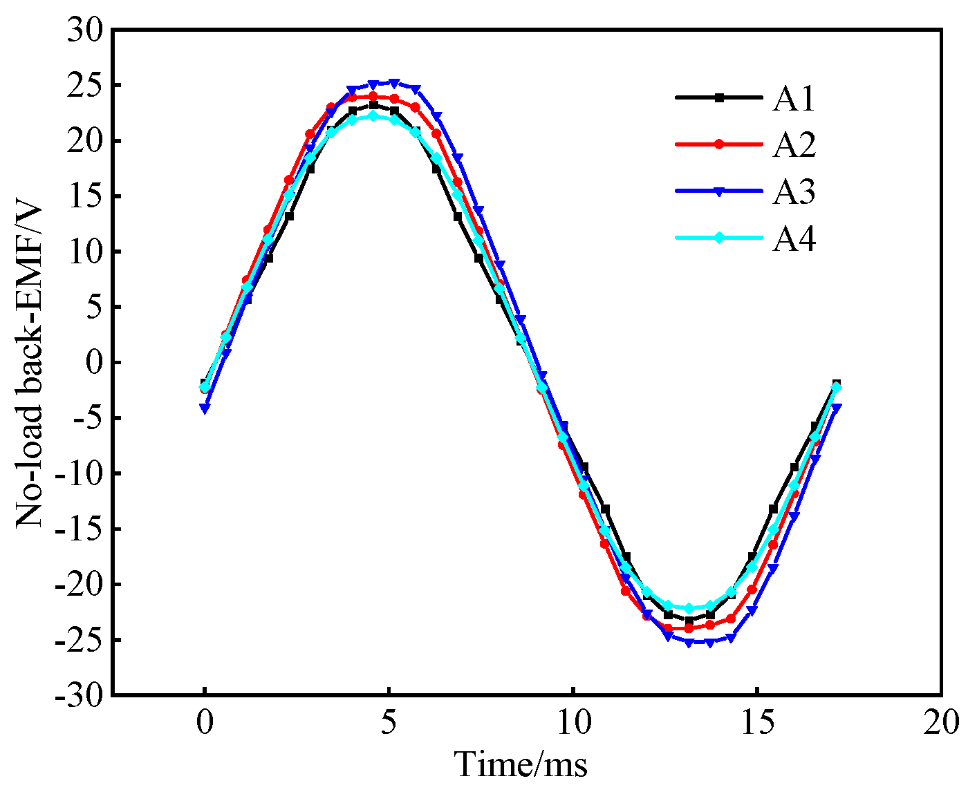
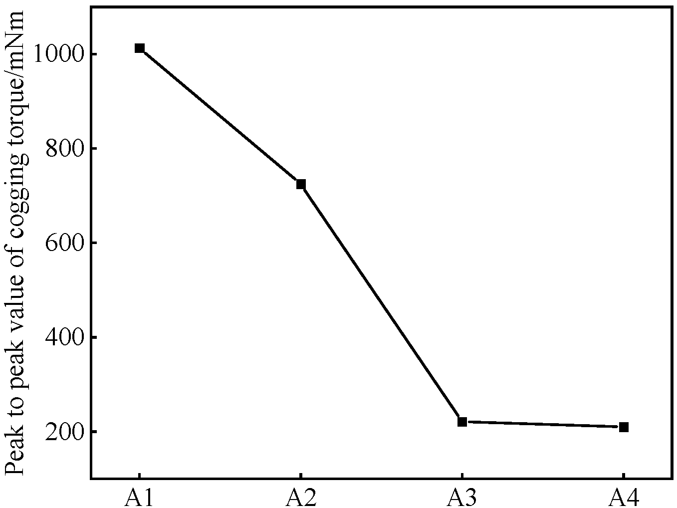
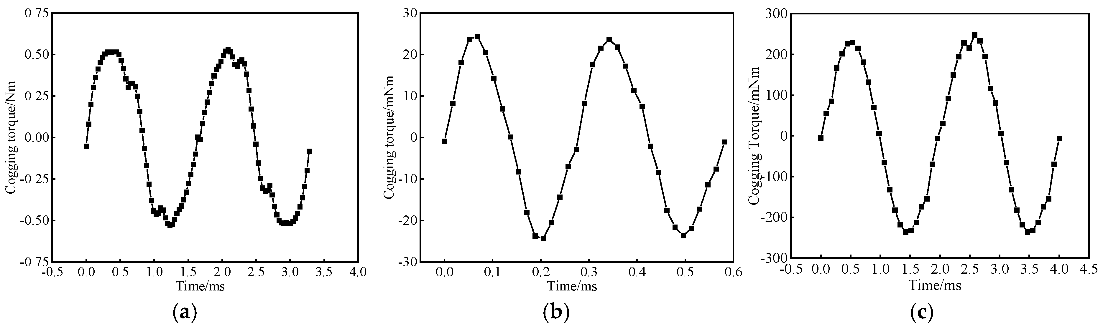
When the motor speed is 500 rpm, the no-load back EMF and cogging torque of different types of PMVMs are analyzed, as shown in
Figure 8 and
Figure 9 below. It can be found that the amplitude of the no-load back EMF of the 6-slot/15-FMP/13-pole-pair PMVM corresponding to A3 is the largest. As the number of FMPs increases and the number of permanent magnet poles increases, the amplitude of the no-load back EMF of six-slot PMVMs first increases and then gradually decreases. At the same time, the peak-to-peak value of cogging torque also gradually decreases. It can be inferred that when the number of FMPs is small, the width of the slot opening is large. As the number of FMPs increases, the slot opening also gradually decreases. Therefore, the number of cogging torque cycles increases and the amplitude decreases.
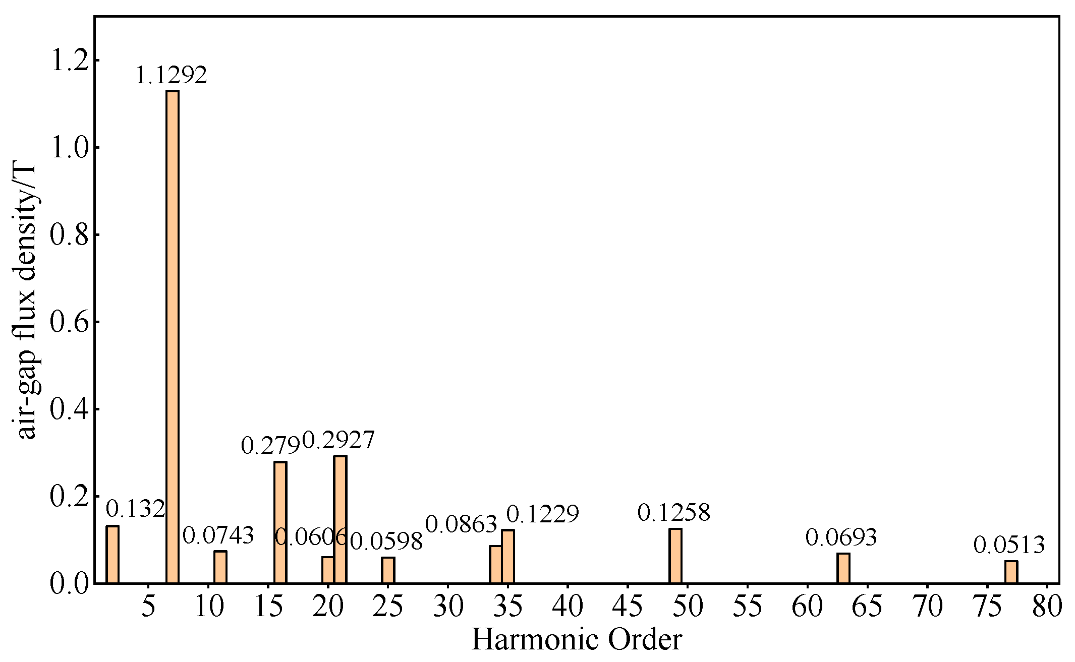
The Fourier decomposition results of the air gap flux density of different six-slot PMVMs under no-load conditions are shown in
Figure 10,
Figure 11,
Figure 12 and
Figure 13. The main harmonics of the six-slot PMVMs are listed in
Table 4. In this table,
is the number of pole pairs for different PMVMs, and
corresponds to the number of FMPs for different PMVMs. The table displays the main harmonic orders of various PMVMs. It can be observed that the 6-slot/9-FMP/7-pole-pair PMVM has the highest number of air gap flux density harmonics, as shown in
Figure 10.
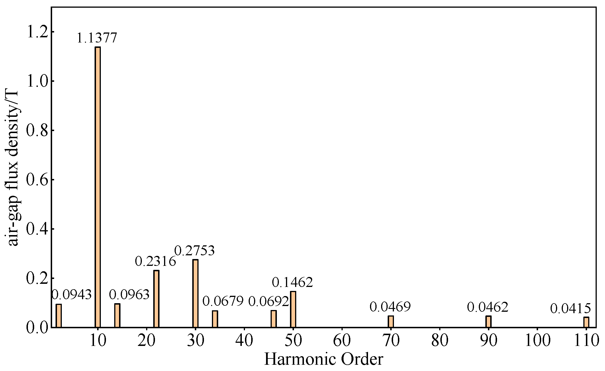
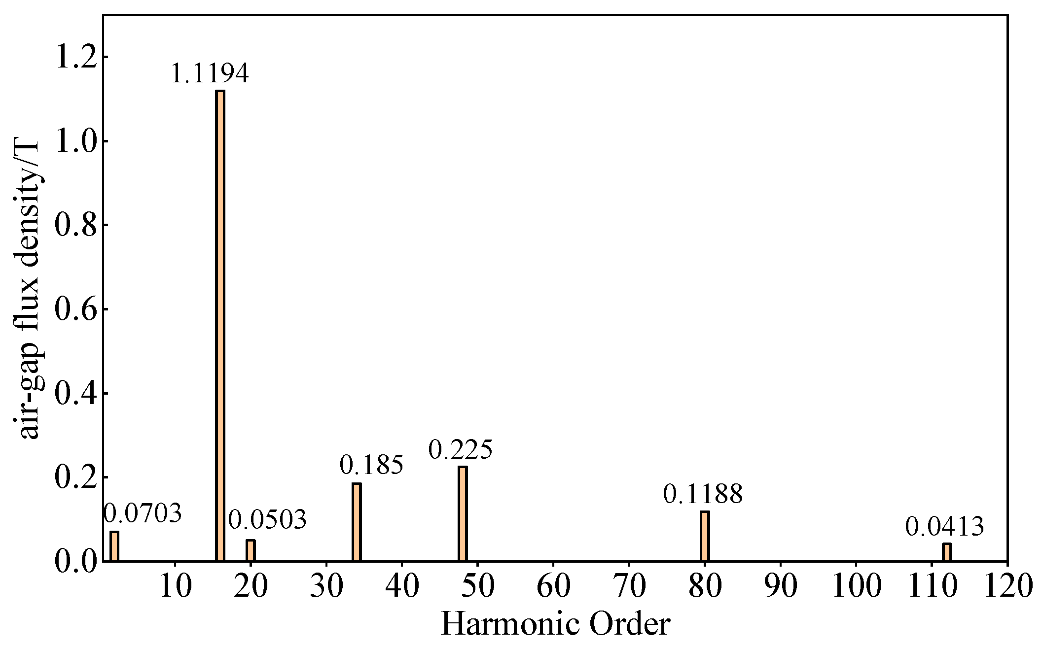
As for
Table 4, it can be observed that with the increase in FMPs and the number of permanent magnet pole pairs, the highest harmonic order of the air gap flux density gradually increases, the fundamental order of the rotor gradually increases, and the amplitude of
-order harmonics gradually decrease, especially in
Figure 11, which is particularly evident.
As the electromagnetic reduction ratio of the PMVMs increases, the amplitude of the -order fundamental wave of the air gap magnetic density gradually increases, and the amplitude of the -order magnetic field modulation harmonic gradually decreases. For the -order magnetic field modulation harmonic, since the number of permanent magnet pole pairs and winding pole pairs of the stator of the PMVMs satisfies the relationship in Equation (1), it can be concluded that for the above four PMVMs, their -order harmonics are all 2. Therefore, when the amplitude of the -order magnetic field modulation harmonic gradually decreases, the number of permanent magnet pole pairs also gradually increases, which can offset the effect of the decrease in the amplitude of the -order harmonic. As can be seen from the torque equation derived from the previous section, the fundamental wave and harmonic have the greatest impact on torque among all harmonic orders. Therefore, as the number of permanent magnet poles increases, the back EMF of PMVMs first increases. However, when the number of permanent magnet poles is too large, the distance between adjacent magnetic poles becomes very small, causing serious problems such as increased magnetic resistance, local saturation, and large leakage flux. Therefore, the back EMF of A4 decreases. In summary, as the number of permanent magnet poles increases, the magnetic field modulation capability of the PMVMs first increases and then decreases.
In addition, the rated torque values of different motors are analyzed under a rated condition with a load current amplitude of 50 A, as shown in
Figure 14. It can be found that as the number of FMPs and the number of permanent magnet poles increase, the average torque of the motor basically first increases and then decreases. At the same time, the torque fluctuation of all motors is greater than 6%, which is speculated to be due to the small number of slots limiting the minimum size of the width of slot openings. As shown in
Figure 15, it can be observed that as the number of FMPs increases, the overload torque coefficient (100 A) first increases and then decreases. This is because increasing the number of permanent magnet pole pairs will increase the electrical frequency of the motor. As the current gradually increases to the overload state, the armature reaction of the motor will be stronger, resulting in a decrease in the power factor and an increase in core loss. Therefore, the overload torque of PMVMs with large numbers of pole pairs is relatively reduced.
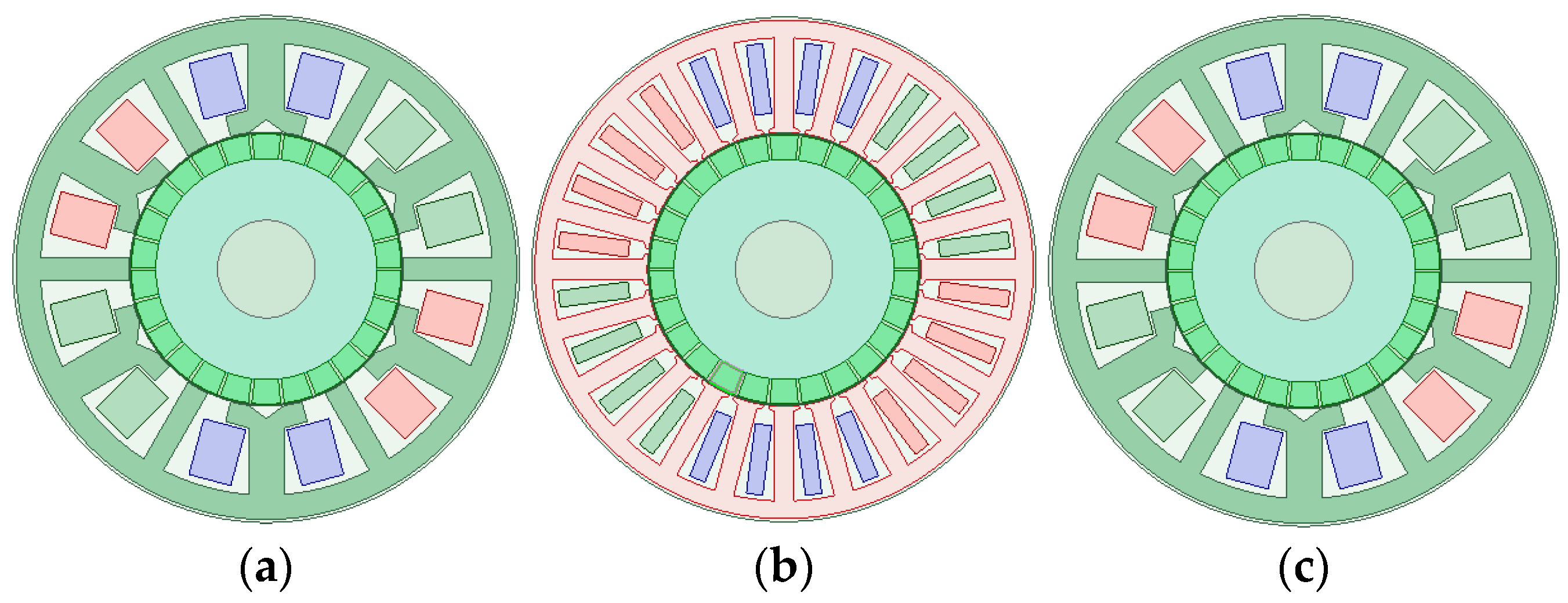
Based on the changing law of number of FMPs and permanent magnet pole pairs of a 6-slot PMVMs, different topological structures of 12-slot PMVMs are determined, as shown in
Figure 16 and
Table 5. Their specific parameters are shown in
Table 4. B1 in
Table 4 corresponds to
Figure 16a, B2 in
Table 4 corresponds to
Figure 16b, B3 in
Table 4 corresponds to
Figure 16c, and B4 in
Table 4 corresponds to
Figure 16d, and B1–B4 corresponds to four 12-slot PMVM topologies in
Figure 16. It should be noted that the outer diameter of the stator and rotor and axial length of the stator and rotor of the 12-slot PMVMs are the same as those of the 6-slot PMVMs.
From
Table 6, it can be concluded that as the number of FMPs and the number of permanent magnet pole pairs increase, the amplitude of the no-load phase back EMF of 12-slot PMVMs first increases and then decreases. The cogging torque of B1 corresponding to 12-slot/18-FMP/13-pole-pair PMVMs is the largest, and the cogging torque of B2 corresponding to 12-slot/24-FMP/19-pole-pair PMVMs is the second largest. After analysis, it can be concluded that this is because the minimum common multiple of their FMP number and the number of permanent magnet pole pairs are relatively small.
In order to conduct a detailed comparative study on the differences in the magnetic field modulation ability of different types of 12-slot PMVMs, Fourier analysis is performed on the no-load air gap magnetic density of different types of 12-slot PMVMs. The results are shown in
Figure 17,
Figure 18,
Figure 19 and
Figure 20 and
Table 7.
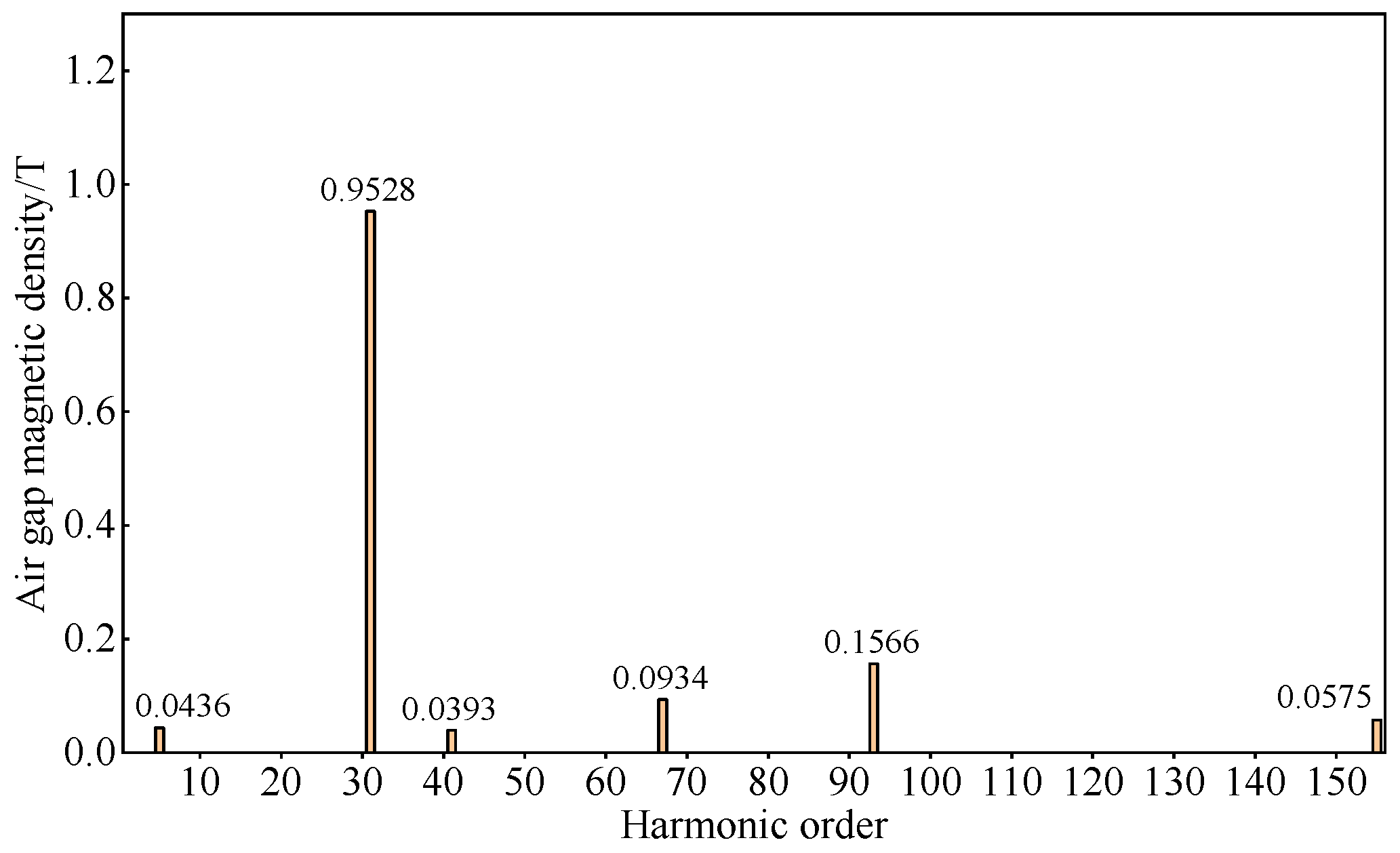
Based on the above results, it can be seen that for 12-slot PMVMs, as the number of FMPs increases, the amplitude of the fundamental order of the rotor first increases and then decreases, and other low-order harmonics gradually decrease, and the magnitude of reduction is greater than that of 6-slot PMVMs. It can be found that this corresponds to the results of six-slot PMVMs.
As the number of FMPs increases, the amplitude of the fundamental magnetic field gradually increases, while the amplitude of the modulation harmonic gradually decreases. However, at this time, the number of permanent magnets also gradually increases, thus offsetting the negative effect of the decrease in the amplitude of the harmonic on the amplitude of the no-load back EMF. Therefore, as the electromagnetic reduction ratio increases, the no-load back EMF first increases. When the number of permanent magnet poles is too large, it causes problems such as local saturation and increased leakage flux, so the no-load back EMF decreases again at this time.
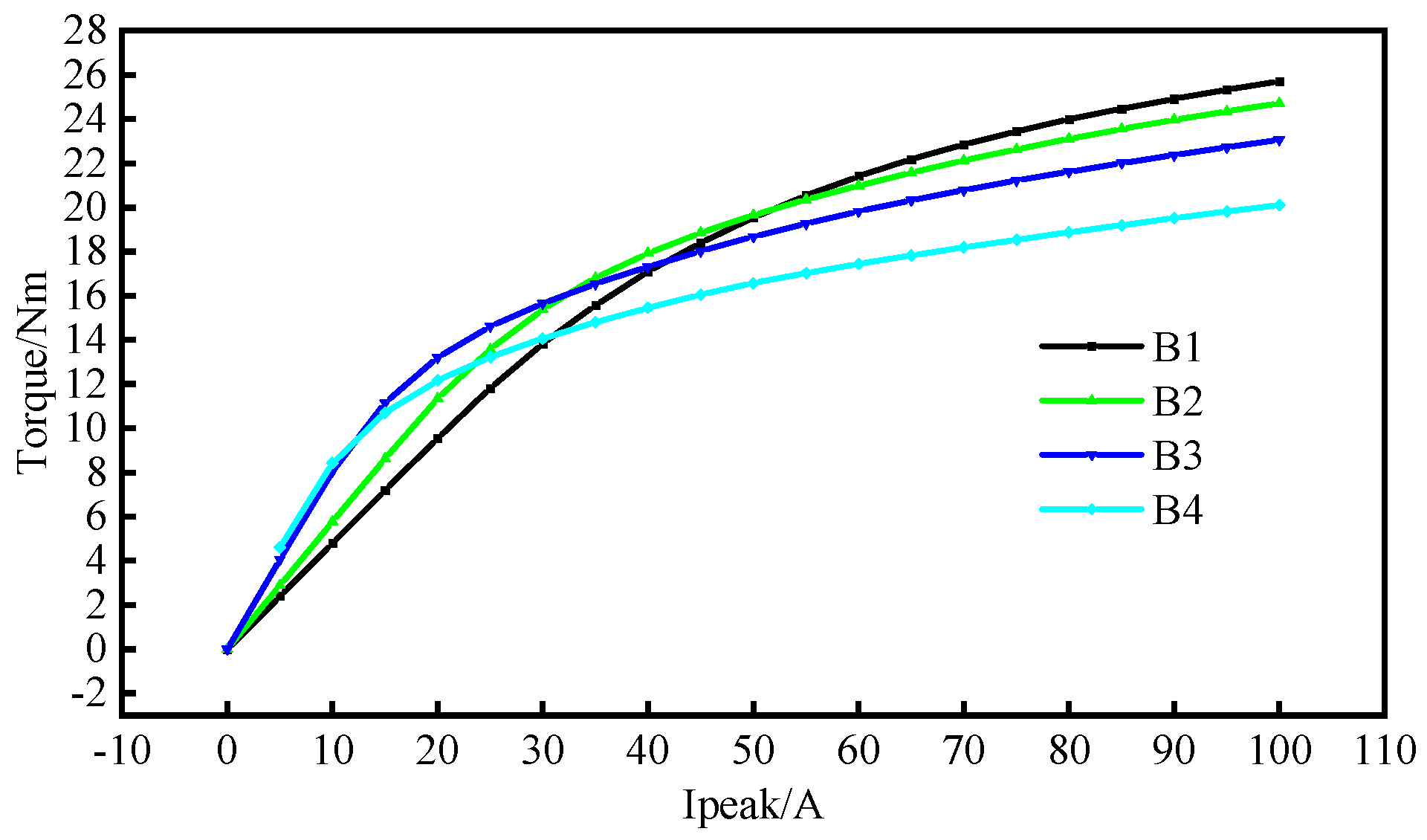
In order to better evaluate the magnetic field modulation capability of different types of 12-slot PMVMs, the torque characteristics of 12-slot PMVMs are analyzed at a rated load current amplitude of 50 A, as shown in
Figure 21. It can be found that as the number of FMPs and permanent magnet poles increases, the average torque of 12-slot PMVMs gradually first increases and then decreases. At the same time, the torque fluctuation values of 12-slot PMVMs are all less than 7%. Compared to the results of six-slot PMVMs, it can be concluded that increasing the number of slots and poles can effectively reduce the motor torque fluctuation.
The torque of 12-slot PMVMs under different load conditions is analyzed, as shown in
Figure 22. It can be seen that as the number of FMPs and the number of permanent magnet poles increase, the overload torque coefficient of the motor gradually decreases when the load current amplitude is 100 A.
Based on the results of 6-slot PMVMs and 12-slot PMVMs, it can be concluded that when the basic structural parameters of the motor remain unchanged, the electromagnetic reduction ratio of PMVMs increases with the increase in the number of FMPs and number of permanent magnet poles. This will lead to an increase in the amplitude of the fundamental modulation order of the magnetic field but a decrease in the number and amplitude of low-order magnetic field modulation harmonics. However, the increase in the number of permanent magnet pole pairs will compensate for the side effect of the decrease in the amplitude of the harmonic.
At the same time, increasing the number of pole pairs of PMVMs within a certain range can enhance the torque performance of the motor. Therefore, in order to ensure that the torque of the motor meets the requirements, for 6-slot PMVMs with an inner diameter less than 82 mm, the number of FMPs on each tooth of the stator should be not over three; for 12-slot PMVMs, the number of FMPs on each tooth of the stator should not exceed two as much as possible.
In order to verify the good fault tolerance of 12-slot PMVMs, self-inductance and mutual inductance are analyzed. As shown in
Table 8, the ratio of mutual inductance to self-inductance is all not greater than 2%. Combined with the results of six-slot PMVMs, it can be concluded that single-layer concentrated windings have high fault tolerance and excellent phase-to-phase isolation capability.
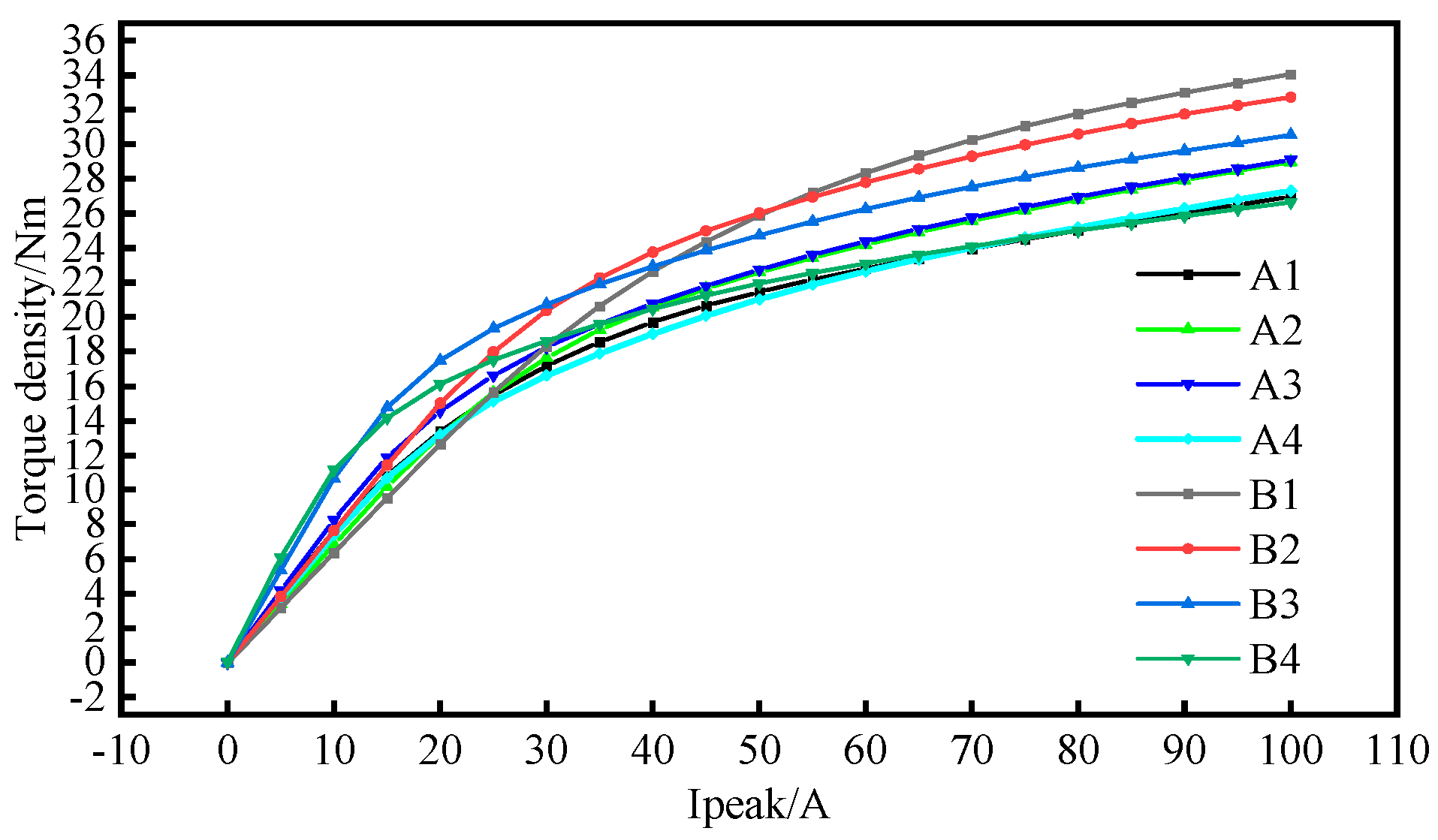
Based on the above research results, in order to accurately evaluate the torque density and torque density coefficient of PMVMs under different slot–pole combinations, the increase in axial length of PMVMs caused by end winding is considered in detail. When the axial lengths of the stator core of 6-slot PMVMs and 12-slot PMVMs are basically the same, 6-slot PMVMs have longer winding ends than 12-slot PMVMs, which causes the axial length of 6-slot PMVMs to be greater than that of 12-slot PMVMs. Based on the above analysis, a modified variation relationship of torque density and current is given, as shown in
Figure 23.
As shown in
Figure 23, as the load current gradually increases, B1 corresponding to 12-slot/18-FMP/13-pole-pair PMVMs has the highest torque density and torque density coefficient, while B2 corresponding to 12-slot/24-FMP/19-pole-pair PMVMs has the second highest torque density and torque density coefficient. It can be seen that 12-slot PMVMs have certain advantages in electromagnetic performance compared to 6-slot PMVMs.


