Article

Stability Analysis and Static–Dynamic Characterization of Subminiature Two-Dimensional (2D) Electro-Hydraulic Servo Valves

College of Mechanical Engineering, Zhejiang University of Technology, Hangzhou 310023, China
*
Author to whom correspondence should be addressed.
Machines 2025, 13(5), 388; https://doi.org/10.3390/machines13050388
Submission received: 2 April 2025 / Revised: 1 May 2025 / Accepted: 5 May 2025 / Published: 6 May 2025
(This article belongs to the Section Electromechanical Energy Conversion Systems)

Abstract

:
Aiming to solve the difficult problem of the miniaturization of servo valves, this paper designs a subminiature two-dimensional (2D) electro-hydraulic servo valve, which realizes the integration of the pilot stage and the power stage and significantly improves the work-to-weight ratio. Meanwhile, a high-power-density brushless DC motor (BLDC) is adopted as the electro-mechanical converter to further reduce the volume and mass. Firstly, the structure and working principle of the two-dimensional (2D) servo valve are described, and the mathematical model of the electro-mechanical converter is established. Aiming at the special working condition of the electro-mechanical converter with high-frequency oscillation at a small turning angle, this paper designs a position–current double closed-loop PID control algorithm based on the framework of the vector control algorithm (FOC). At the same time, the current feedforward compensation technique is included to cope with the high-frequency nonlinear disturbance problem of the electro-mechanical converter. The stability conditions of the electro-mechanical converter and the main valve were established based on the Routh–Hurwitz criterion, and the effects of the control algorithm of the electro-mechanical converter and the main parameters of the main valve on the stability of the system were analyzed. The dynamic and static characteristics of the 2D valve were simulated and analyzed by establishing a joint simulation model in Matlab/Simulink and AMESim. The prototype was fabricated, and the experimental bench was built; the size of the experimental prototype was 31.7 mm × 29.3 mm × 31 mm, and its mass was 73 g. Under a system pressure of 7 MPa, the flow rate of this valve was 5 L/min; the hysteresis loop of the spool-displacement input–output curve was 4.8%, and the linearity was 2.54%, which indicated that it had the ability of high-precision control and that it was suitable for the precision fluid system. The step response time was 7.5 ms, with no overshoot; the frequency response amplitude bandwidth was about 90 Hz (−3 dB); the phase bandwidth was about 95 Hz (−90°); and the dynamic characterization experiment showed that it had a fast response characteristic, which can satisfy the demand of high-frequency and high-dynamic working conditions.

1. Introduction

The electro-hydraulic servo valve is an important component in an electro-hydraulic control system; it plays the role of electro-hydraulic conversion and power amplification in the system [1] and is widely used in robotics [2], industrial automation, aerospace [3], and other fields. With the rapid development of robotics [4,5], biological exoskeletons [6], and other emerging technologies, the demand for lightweight equipment, miniaturization, and high integration of the hydraulic drive system presents a new challenge. However, the traditional electro-hydraulic servo valves have difficulties in meeting these demands due to their large size and low power-to-weight ratio [7,8].
Traditional servo valves can be categorized into nozzle–baffle valves, jet pipe valves, and similar types according to their structure. The nozzle–baffle valve realizes inter-stage feedback through the feedback lever, which has the advantages of high sensitivity and good static–dynamic performance, but its anti-pollution ability is poor, and its structure is complicated [9,10]; while the jet pipe valve has excellent anti-pollution ability due to its unique pilot-stage design [11], the jet flow field is complicated, and its characteristics are difficult to model accurately [12,13]. Researchers have begun to explore new valve structures in response to the shortcomings of traditional servo valves. Zhao et al. [14] proposed a new type of pilot-controlled servo valve with a flow rate of 293 L/min by using a structure in which two pilot stages cooperate with each other to control the movement of the two main spools, but the multistage structure results in a large volume mass and a low power-to-weight ratio. Zhang et al. [15] designed a servo valve with a rated flow rate of 0.7 L/min by optimizing the mechanical structure and magnetic circuit mechanism.
Obayashi et al. [16] designed a servo valve with a mass of 73 g and a rated flow rate of 1 L/min by adopting the flexure tube flow control technique and optimizing the valve body structure. The servo valves designed in Refs. [15,16] are all direct-driven without a pilot structure, which reduces the volume and mass of the valve body but sacrifices the servo valve’s mass and weight. Although direct-driven valves reduce the volume and mass of the valve body, they sacrifice the control accuracy and response speed of the servo valve, and the flow rate of the direct-driven valve is small, and the power-to-weight ratio is not ideal, which cannot meet the demand for miniaturization and high power-to-weight ratio in the field of robotics.
The electro-hydraulic servo valve’s performance is not only closely related to the valve body itself but also has an important connection with the electro-mechanical converter. The function of electro-mechanical converters is to convert electrical signals into displacement or torque, and common types of electro-mechanical converters are torque motors and proportional solenoids. A torque motor has the advantages of small inertia, large thrust, and rapid dynamic response, but it is affected by the air gap changes and material hysteresis; the nonlinearity of the output characteristics is more serious, and the torque motor is large, which makes it difficult to achieve a high degree of integration and miniaturization [17,18]. Meng Bin et al. [19] propose a single-phase permanent magnet torque motor for the problems of magnetic circuit complexity, structural redundancy, and output nonlinearity, and the optimized torque-angle characteristic is nearly linear, but the output angle is still small. The proportional electromagnet has a long working stroke and large thrust, but the armature assembly has large inertia and low dynamic response. Yu et al. [20] optimized the structural parameters of the proportional electromagnet based on three-dimensional finite element simulation, so that the average electromagnetic force was improved by 20.1%, and the effective stroke was extended to 2.1 mm. However, the proportional electromagnet itself relies on the electromagnetic force and the spring equilibrium, and the dynamic response is poor, and it is difficult to realize high-frequency oscillation control. Today, researchers are constantly trying to apply new materials to electro-mechanical converters, such as piezoelectric ceramic actuators and shape memory alloys. A piezoelectric ceramic actuator has a high dynamic response and a Japanese team developed a piezo-ceramic direct-acting servo valve with a frequency width of 5 k Hz, but its output displacement was only in the micrometer scale, and the flow rate was only 0.2 L/min [21]. Additionally, it required a kilovolt-level operating voltage, which cannot meet the low-power demands of robotics. Shape memory alloy (SMA) offers a large displacement output and a simple structure but suffers from slow response and limited bandwidth, and it relies on the thermal cycle drive; the control accuracy is low, and thermal fatigue also easily leads to material performance degradation [22]. In contrast, brushless DC motors (BLDC) have the advantages of simple structure, high air-gap magnetic density, high power density, high-frequency response, and large torque-to-current ratio, which is an important innovative direction for servo valve drives [23,24].
Based on the above, this paper innovatively proposes a subminiature two-dimensional (2D) electro-hydraulic servo valve based on a servo spiral mechanism, which realizes the integration of the pilot stage and the power stage by coupling the spool rotation and axial displacement double-degree-of-freedom motions and significantly improves the power-to-weight ratio [25]. In addition, a high-power-density BLDC is adopted as the electro-mechanical converter, which is smaller in size and faster in response than the previous electro-mechanical converter. Compared with other electro-mechanical converters, brushless DC motors in small servo valves offer significant safety and reliability advantages: their brushless design eliminates the risk of brush wear and sparking, making them suitable for long-term continuous operation. Closed-loop control and high-precision feedback, combined with low-torque pulsation and anti-electromagnetic interference characteristics, ensure stable control of the spool and avoid fluctuations in flow rate or system instability. Aiming at the special working conditions of the electro-mechanical converter with a small corner oscillation, a position–current double closed-loop PID control algorithm was designed on the basis of the FOC. The sample valve had a volume of 31.7 mm × 29.3 mm × 31 mm, a mass of 73 g, and a flow rate of 5 L/min at a system pressure of 7 MPa. It possesses a higher power-to-weight ratio relative to the literature [14,15,16]. The rest of the paper is organized as follows: Section 2 introduces the structure and working principle of the 2D servo valve; Section 3 establishes the mathematical model of the electro-mechanical converter and the valve body and deduces the sufficient conditions for the stability of the system based on the Routh–Hurwitz criterion; Section 4 establishes a co-simulation model using MATLAB/Simulink and AMESim and researches the dynamic–static characteristics and the influence of important parameters on the dynamic characteristics of the valve body. In Section 5, an experimental platform is built to test its dynamic and static characteristics, and the experimental results are compared with the simulation analysis, and finally, the conclusions of this paper are drawn in Section 6.

2. Structure and Working Principle of the 2D Servo Valve

The structure of the 2D servo valve is shown in Figure 1a. It primarily consists of a valve body, a servo spiral mechanism, an electro-mechanical converter (BLDC motor), a transmission mechanism (cam–guide–rod mechanism), and an angular displacement sensor (AS5045 magnetic encoder). The valve employs a hydraulic-resistance half-bridge formed by two tiny bow-shaped areas—intersecting between the helical grooves on the valve sleeve and a pair of high-/low-pressure holes on the spool’s right shoulder—to regulate the pressure in the left chamber. This design integrates the pilot and power stages into a single spool with two degrees of freedom.
The initial transmission mechanism of the prototype used rack-and-pinion and fork-lever drives. While the gear transmission theoretically provides linear input–output relationships, practical issues such as backlash-induced nonlinearity, high starting force, and complex zeroing were observed. The fork-lever mechanism, despite its simplicity, suffered from low precision and wear susceptibility. The current design adopts a cam–guide–rod mechanism. By leveraging an eccentric cam profile (eccentric distance: e ) and a symmetrically preloaded structure to eliminate backlash, this mechanism precisely controls the spool rotation angle. Additionally, a central magnet enables automatic centering upon power loss, achieving high precision, compactness, and miniaturization.
The AS5045 magnetic encoder provides real-time feedback of the mechanical angular displacement θ s from the electro-mechanical converter and converts it into an electrical angular signal. This signal serves two purposes: (1) as the position input for the position PID controller, whose output drives the current PID controller; and (2) as the reference angle for subsequent coordinate inverse transformations.
Figure 1b shows the physical prototype of the 2D servo valve. The valve body is fabricated via binder jetting technology, which enables single-step molding of complex thin-walled flow channels without requiring a heat source or support structures. This process involves layer-by-layer binder spraying to bond metal powder, followed by degreasing and sintering [26,27,28].
The 2D servo spiral mechanism adjusts the sensitive cavity pressure via the overlapping area between the slant grooves and high-/low-pressure holes. At the spool’s neutral position (Figure 2a), the overlap areas of the high-/low-pressure holes with the slant grooves on the valve sleeve are equal. Consequently, the sensitive cavity pressure equals half of the left cavity pressure, and the left cavity’s effective area on the spool is half that of the right cavity. This balance maintains axial force equilibrium, keeping ports A and B closed. When the spool rotates counterclockwise, the overlap area with the high-pressure hole increases while that with the low-pressure hole decreases. This raises the sensitive cavity pressure above that of the high-pressure cavity, driving the spool leftward until equilibrium is restored (Figure 2a). Reverse rotation results in the equilibrium state shown in Figure 2b.

3. Stability Analysis of Subminiature Two-Dimensional (2D) Electro-Hydraulic Servo Valve

3.1. Stability Analysis of Electro-Mechanical Converter Control Algorithm

3.1.1. Mathematical Model of Electro-Mechanical Converter

The BLDC in this study adopts a star-connected configuration. Ignoring factors such as torque ripple, magnetic saturation, and eddy current loss, the voltage balance equations for its three-phase stator windings are given as follows [29]:
U A U B U C = R A 0 0 0 R B 0 0 0 R C i A i B i C + L M 0 0 0 L M 0 0 0 L M d d t i A i B i C + e A e B e C
The electromagnetic torque equation of the converter is as follows:
T e = e A i A + e B i B + e C i C / ω
To summarize, the equation of motion of the electro-mechanical converter is as follows:
T e T L = J d ω d t + B v ω

3.1.2. Control Strategies for Electro-Mechanical Converters

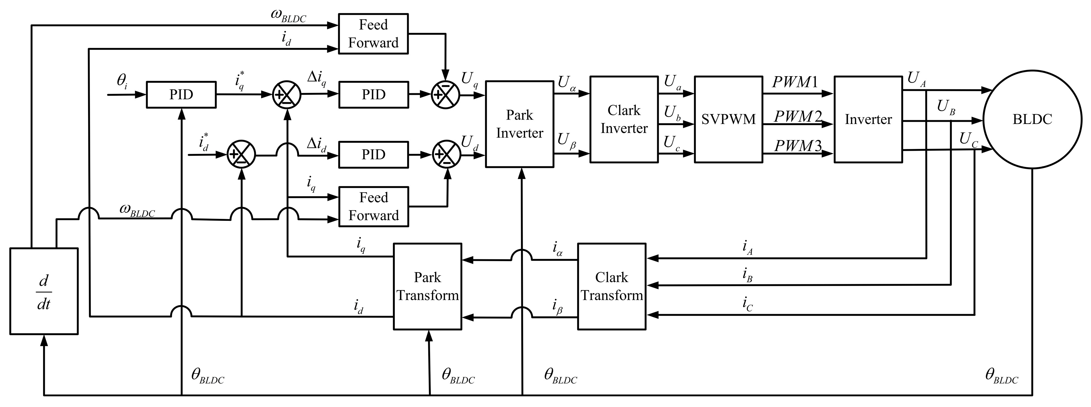
Theoretical analysis shows that the performance of the electro-mechanical converter is influenced by electromagnetic torque. Improving the electromagnetic torque is the key to enhancing its performance, making the adoption of an advanced control strategy crucial. Aiming at the special working condition of an electro-mechanical converter with high-frequency oscillation at a small turning angle, this paper designs a position–current double closed-loop PID control algorithm based on the framework of the vector control algorithm (FOC). At the same time, the current feedforward compensation technique is included to cope with the high-frequency nonlinear disturbance problem of the electro-mechanical converter. The FOC is currently one of the most efficient control methods for BLDC [30]. The position–current double-closed-loop control strategy is used in the FOC, which has the advantages of reducing the delay of the control link, eliminating the influence of the velocity-loop coupling, and having lesser difficulty in parameter integration, relative to the position–velocity–current triple closed loop. SVPWM is an efficient power electronics modulation technique. Its core function is to convert the voltage references generated by the control algorithm into switching signals for the three-phase inverter, enabling precise motor control. By optimizing the synthesis of voltage vectors, SVPWM maximizes the DC bus voltage utilization, reduces harmonic distortion and switching losses, and significantly enhances the system’s dynamic response performance and control accuracy [31]. To eliminate inter-phase coupling and reduce control complexity, the mathematical model of the electro-mechanical converter is typically transformed into a two-axis planar coordinate system. The three-phase currents are decoupled into two-dimensional orthogonal vectors through the Clarke transform and the Park transform.
The Clarke transform converts the three-phase stationary coordinate system (A-B-C) into the two-phase stationary coordinate system (α-β), and the current transformation matrix is given as follows:
i α i β = 2 3 1 0 1 2 3 2 1 2 3 2 i A i B i C
The Park transform converts the two-phase stationary coordinate system (α-β) into the two-phase rotating coordinate system (d-q), and the current transformation matrix is expressed as follows:
i d i q = cos θ sin θ sin θ cos θ i α i β
The voltage balance equation of the electro-mechanical converter in the two-phase rotating coordinate system (d-q) is given by the following:
u d = R s i d + L d d i d d t ω L q i q u q = R s i q + L q d i q d t + ω L d i d + ω ψ f
From Equation (6), in the d-q coordinate system, the cross terms ω L q i q exist in the d-axis voltage equation, indicating that the d-axis voltage u d is coupled with the rotational speed ω and the q-axis current i q . At high frequencies, these coupling terms degrade the current-loop control performance, necessitating decoupling control. This paper proposes a feedforward compensation method to eliminate the coupling effects on the d-axis current loop, thereby improve the system’s dynamic response performance. When using the FOC algorithm, in order to ensure the maximum electromagnetic torque output of the electro-mechanical converter, generally make i d = 0 , i.e., the electromagnetic torque is determined by i q , resulting in a linear torque–current relationship and optimal efficiency. In summary, the control algorithm block diagram of the electro-mechanical converter is illustrated in Figure 3. After incorporating feedforward compensation, its voltage balance equation in the d-q coordinate system is expressed as follows:
u d = 0 u q = R s i q + L q d i q d t
The electromagnetic torque equation of the electro-mechanical converter can be expressed in the d-q coordinate system as follows:
T e = 3 2 P e ψ f i q

3.1.3. Transfer Functions of Electro-Mechanical Converters

From Equation (7), the transfer function of the electrical model of the electro-mechanical converter is derived as follows:
G elec ( s ) = i q s u q s = 1 L q s + R s
The SVPWM and inverter model can be approximated as a gain component and a time delay. By ignoring the SVPWM delay T svpwm = 0 , the transfer function of the SVPWM and inverter is as follows:
G svpwm ( s ) = u q s u q * s = K svpwm 1 + T svpwm s K svpwm
Since the electro-mechanical converter is unloaded, combining Equations (3) and (8), the transfer function for position θ BLDC and the q-axis current i q is as follows:
G mech ( s ) = θ BLDC ( s ) i q ( s ) = K t s J s + B
K t = 3 2 P e ψ f
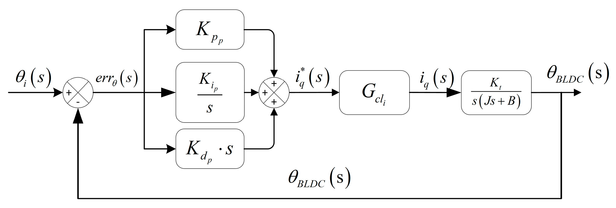
The position loop employs an incremental PID control algorithm, while the current loop utilizes a PID control algorithm. The block diagram of the model transfer function for the electro-mechanical converter is shown in Figure 4.
Since the bandwidth of the current loop is much higher than that of the position loop, i.e., G cl i s 1 , the transfer function of the electro-mechanical converter is simplified to the following:
G cl p s = θ BLDC s θ i s = G open p s 1 + G open p s K t K d p s 2 + K P p s + K i p J s 3 + B + K t K d p s 2 + K t K P p s + K t K i p

3.1.4. Stability Analysis of Electro-Mechanical Converters

Based on Equation (14), the characteristic equation of the electro-mechanical converter is derived, and the necessary and sufficient condition for system stability is determined via the Routh–Hurwitz criterion as follows:
( B + K t K d p ) K P p > J K i p
From Equation (15), increasing the proportional gain coefficient K P p , derivative gain term K d p , or damping coefficient B will increase the term ( B + K t K d p ) K P p , thereby making the inequality easier to satisfy. Conversely, decreasing the moment of inertia J or integral gain K i p will reduce the term J K i p , which also facilitates satisfying the inequality condition.

3.2. Stability Analysis of 2D Servo Screw Mechanism

3.2.1. Mathematical Model of 2D Servo Screw Mechanism

Figure 5 illustrates the geometric relationship diagram of the servo spiral mechanism.
Based on the study of the servo spiral mechanism by Li et al. [20], the flow continuity equation of the sensitive cavity is as follows:
Q 1 + Q l 1 Q 2 Q l 2 = A s d x v d t + V 1 β e d P c d t
Based on the working principle of the servo spiral mechanism, the overlap height h 1 , h 2 of the high-/low-pressure ports and the helical grooves can be derived as follows:
h 1 = h 0 + R θ sin β x v cos β h 2 = h 0 R θ cos β + x v cos β
Under static conditions, h 1 = h 0 , the relationship between the initial arch height h 0 , spool rotation angle θ , and spool axial displacement x v is expressed as follows:
x v = R θ tan β
The overlap area between the high-/low-pressure ports and the helical grooves A 1 , 2 is determined by their positional relationship:
A 1 , 2 = 0 h 1 , 2 < 0 h 1 , 2 2 r d h 1 , 2 h 1 , 2 2 + r d 2 arcsin 2 r d h 1 , 2 h 1 , 2 2 r d r d 2 r d h 1 , 2 h 1 , 2 2 0 < h 1 , 2 r d π r d 2 + h 1 , 2 2 r d h 1 , 2 h 1 , 2 2 r d 2 arcsin 2 r d h 1 , 2 h 1 , 2 2 r d r d 2 r d h 1 , 2 h 1 , 2 2 r d < h 1 , 2 2 r d π r d 2 h 1 , 2 2 r d
The flow rate into the sensitive cavity, denoted as Q 1 , is obtained as follows:
Q 1 = C d A 1 2 ( P s P c ) / ρ
The flow rate out of the sensitive cavity, denoted as Q 2 , is obtained as follows:
Q 2 = C d A 2 2 P c ρ
Based on the force equilibrium principle, the spool force balance equation is given by Equation (21):
A s P c P s 2 = m d 2 x v d t 2 + B p d x v d t + F L
The closed-loop control block diagram of the 2D servo spiral mechanism is shown in Figure 6.
The closed-loop transfer function of the 2D servo spiral mechanism is as follows:
G cl body ( s ) = x v ( s ) θ valve ( s ) = K 1 A s R sin β m A s L v β p s 3 + B p A s L v β p + m K 2 s 2 + A s 2 s + K 1 A s cos β
K 1 = 4 C d P s ρ 2 h 0 r d h 0 2
K 2 = 2 C d [ r d 2 arcsin 2 r d h 0 h 0 2 r d r d h 0 2 r d h 0 h 0 2 ] 1 P s ρ

3.2.2. Stability Analysis of the 2D Servo Screw Mechanism

By combining Equations (22)–(24), the characteristic equation of the 2D servo spiral mechanism is derived, and the necessary and sufficient condition for system stability is determined via the Routh–Hurwitz criterion as follows:
B c A s L v β e + 2 m C d P s ρ r d 2 arcsin 2 r d h 0 h 0 2 r d r d h 0 2 r d h 0 h 0 2 > 4 m L v C d β e P s ρ 2 h 0 r d h 0 2 cos ( β )
The inclination angle β of the helical groove exists only in the cosine term of the inequality’s right-hand side, β 0 , π 2 . As β increases, the cos β decreases, leading to a reduction in the overall value of the right-hand side. This makes the inequality easier to satisfy, indicating enhanced stability of the 2D servo spiral system. However, Equation (18) shows that, if the spool rotation angle θ valve remains constant, reducing β increases the spool axial displacement x v , thereby degrading the control accuracy of the 2D servo spiral mechanism. Therefore, the optimal value of β must be determined through simulation to balance the system stability and control accuracy.
The high-pressure bore radius r d exists on both the left and right sides of the inequality, and the left term increases approximately in proportion to r d 2 , while the right term increases approximately in proportion to r d , which clearly shows that the left term grows faster than the right term. As the high-pressure bore radius r d increases, the inequality is more likely to hold, i.e., the 2D servo helix system is more stable. As shown in (19) and (20), when the spool angle θ valve is not changed, increasing the high-pressure bore radius r d increases the overlap area A 1 between the high-pressure orifice and the servo helix groove, and the flow rate of the sensitive cavity increases, which improves the dynamic response speed of the spool. However, due to the existence of inertia of the system, when the spool responds faster, the spool will easily cause an overshoot when it reaches the target position, and it will even cause the system to oscillate. Therefore, it is necessary to determine the optimal value of the high-pressure bore radius r d through simulation to balance the system stability and response speed.

4. Combined Dynamic and Static Characteristic Simulation Analysis of the Subminiature Two-Dimensional (2D) Electro-Hydraulic Servo Valve

In order to investigate the influence of key structural parameters such as oil supply pressure, high-pressure port radius, inclination angle of the helical groove, and other parameters on the dynamic response of the 2D servo valve, a co-simulation model was developed using AMESim (2021.1) and Matlab(R2022b)/Simulink. By integrating the advantages of both software platforms in hydraulic system modeling and control algorithm design, this model provides a technical basis for prototyping the experimental system.

4.1. Simulation Model of the Electro-Mechanical Converter

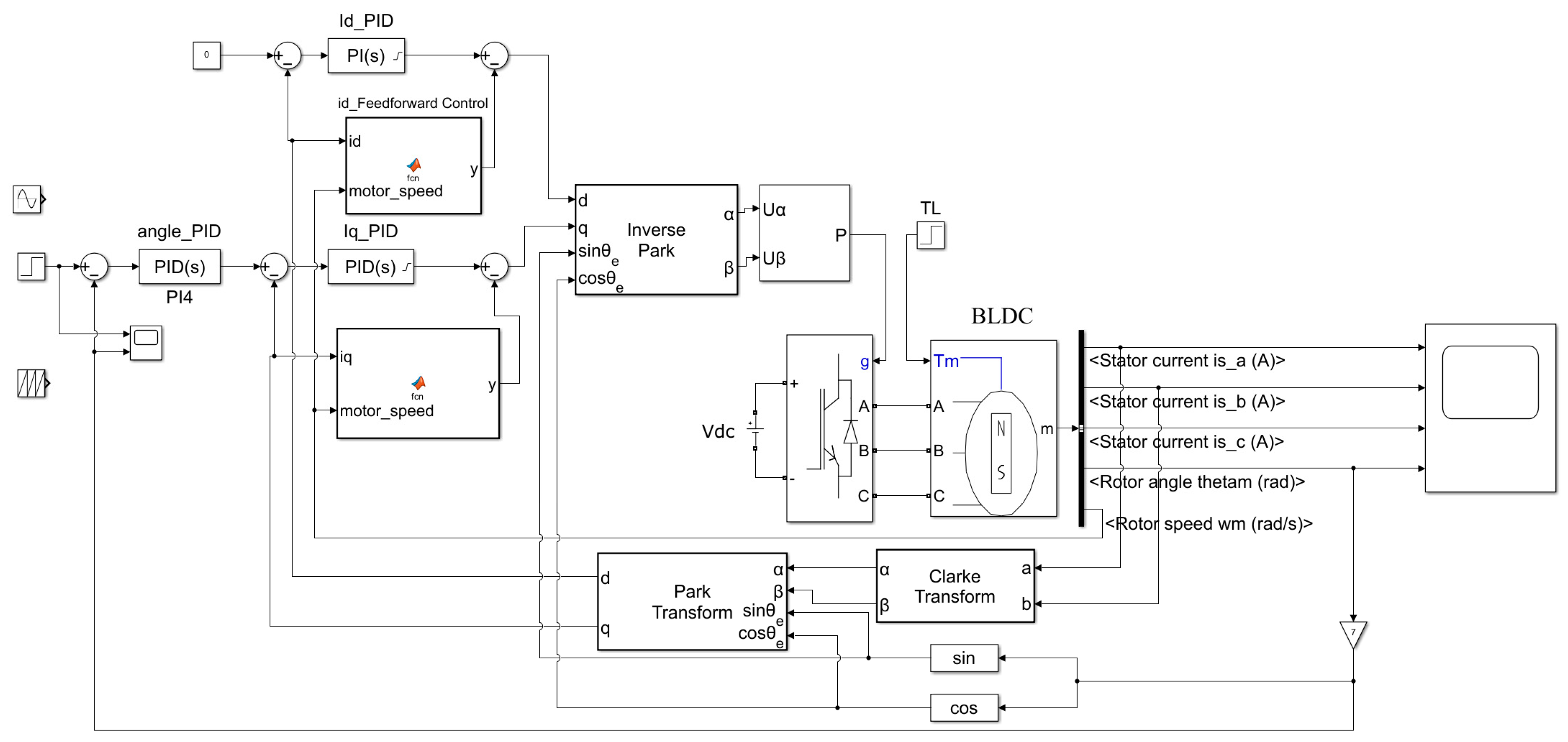
Figure 7 shows the simulation model of the electro-mechanical converter control algorithm built in the Matlab/Simulink environment, which is based on the above control strategy and adopts the FOC framework to design the position–current dual PID closed-loop control algorithm, combined with the current feedforward algorithm. The AS5045 magnetic encoder is also set to provide accurate position feedback, which realizes the decoupling of d-q axis current control and maximum torque-to-current ratio control. The converter’s parameters listed are in Table 1.

4.2. Combined Simulation Mode

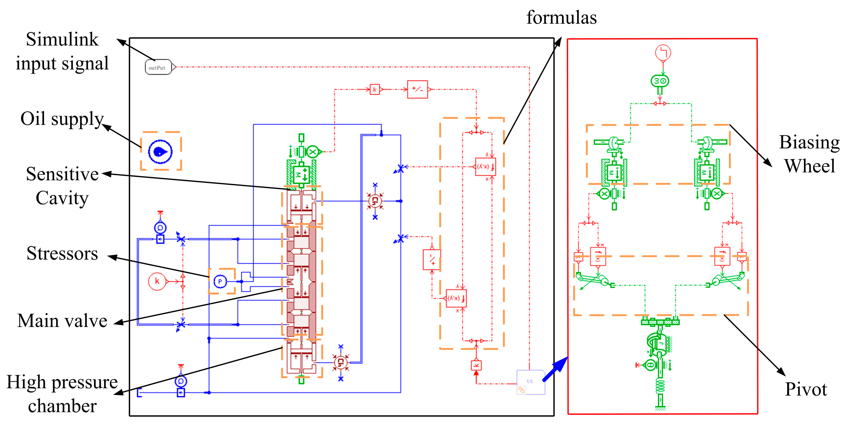
The cam guide and the main valve are built based on AMESim, and the eccentric wheel is rotated by the angular displacement of the electro-mechanical converter and the spool is rotated by the toggle lever; based on Equations (18) and (19), the overlap area function of the high- and low-pressure orifices is established, and the simulation models of the servo helical mechanism and the main valve are established by using the size of the overlap area of the variable throttles to simulate the size of the overlap area. The dynamic and static characteristics of the 2D servo valve were jointly simulated and analyzed by using the Matlab/Simulink simulation model of the electro-mechanical converter and the AMESim simulation model of the valve body drive mechanism, and the joint simulation model is shown in Figure 8. Table 2 shows the main parameter settings of the co-simulation model. The joint simulation model investigates the effects of structural parameters, such as oil supply pressure, inclination angle of the inclined groove, and radius of the high-pressure orifice, on the dynamic response of the 2D servo valve.

4.3. Static Characteristic Simulation Analysis

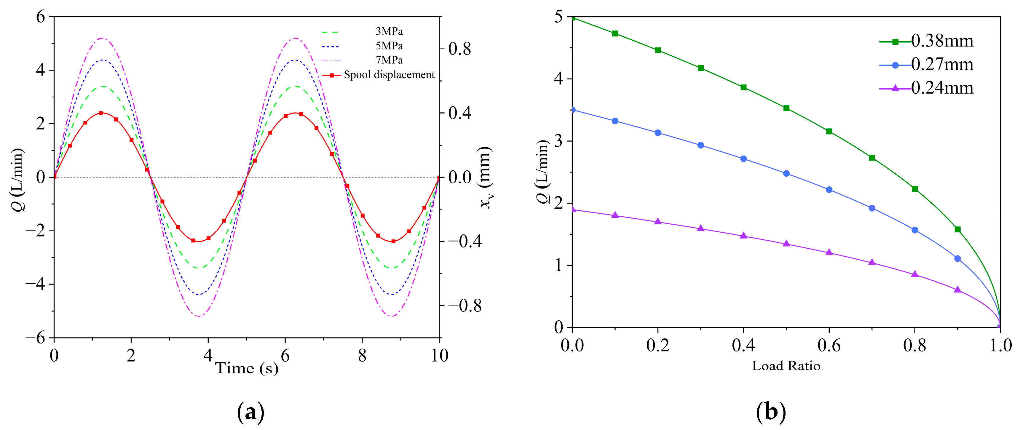
Figure 9a shows the no-load flow characteristic curve of the 2D servo valve. The spool input signal was a 0.1 Hz full-scale sine wave, and the system pressure was set to 3 MPa, 5 MPa, and 7 MPa, respectively. The results indicate that the 2D servo valve exhibits excellent flow-following characteristics under no-load conditions, and the operating flow rate is positively correlated with the system pressure.
Figure 9b illustrates the load flow characteristic curve of the 2D servo valve. The results demonstrate a negative correlation between the flow rate and load pressure ratio. When the load pressure ratio reached 100%, the working port flow rate dropped to 0 L/min. Due to the lack of a pressure compensation mechanism, the flow rate decreased with rising load pressure, resulting in non-flattened load flow characteristics.

4.4. Dynamic Characteristic Simulation Analysis

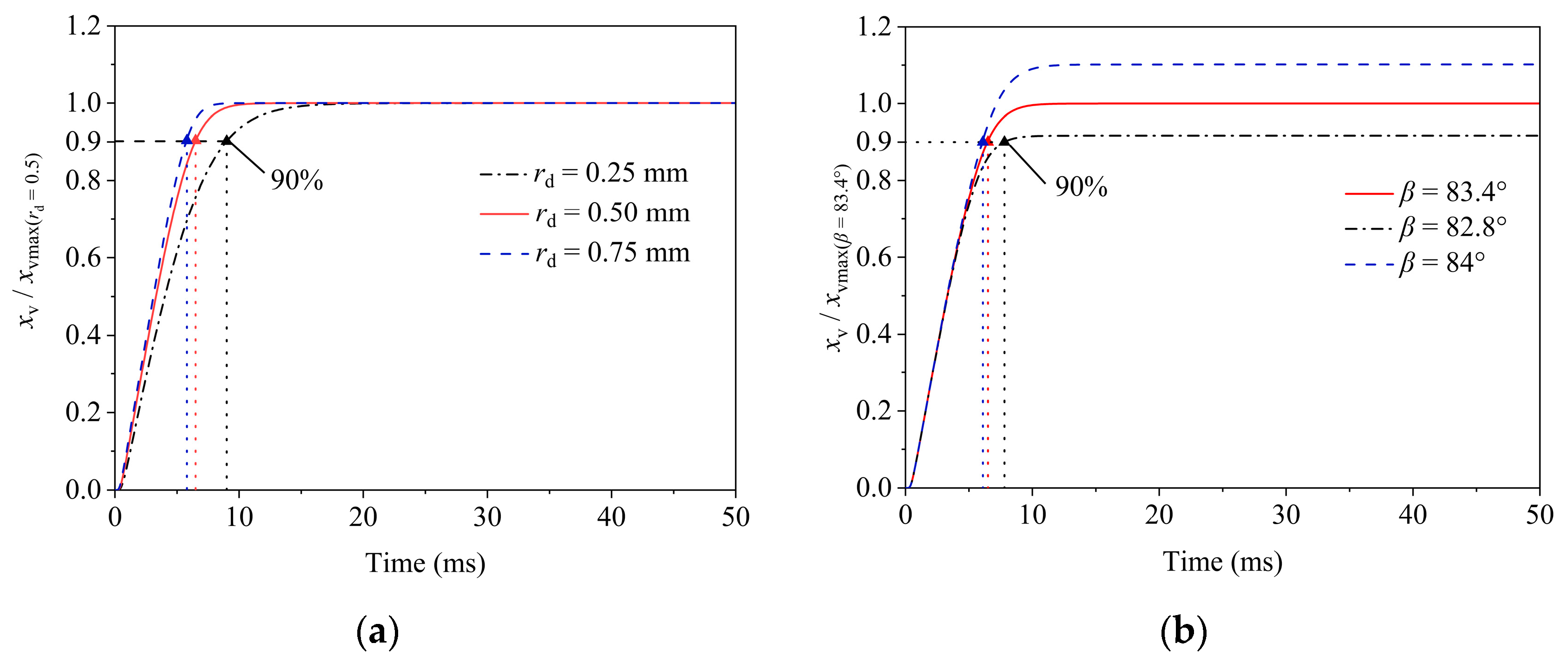
Figure 10 shows the step response curve of the 2D servo valve for different key parameters. The step curve is overdamped without any overshoot and oscillation at full-scale input. In Figure 10a, the simulation results show that the system response time was 9 ms, 6.5 ms, and 5.7 ms when the radius of the high-pressure orifice was 0.25 mm, 0.5 mm, and 0.75 mm, respectively. According to Equations (17)–(20), increasing the radius of the high-pressure orifice, the overlap area between the spiral groove and the high-pressure and low-pressure orifices increases, which results in an increase in the inflow into the sensitive cavity and thus improves the response speed of the system.
Figure 10b shows that, when the inclination angle of the helical groove was 82.8°, 83.4°, and 84°, the system response times were 5.9 ms, 6.5 ms, and 7.1 ms, respectively, suggesting a minor effect of the inclination angle on response speed. As per Equation (18), increasing the inclination angle raises the spool axial displacement, thereby altering the steady-state flow rate and affecting the system’s steady-state performance.

5. Experimental Research

5.1. Test Bench

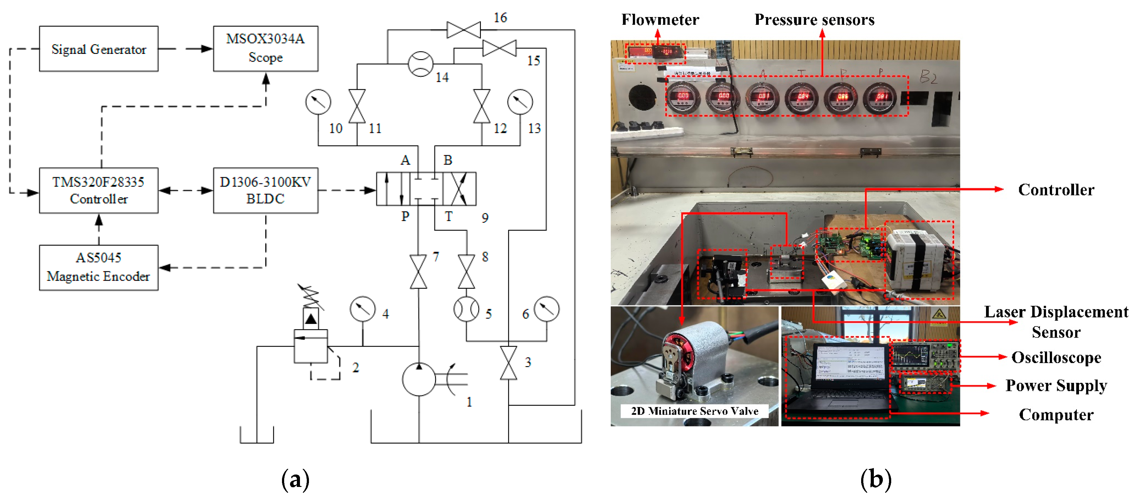
The hydraulic circuit diagram of the 2D servo valve test bench is shown in Figure 11a, which was utilized to evaluate the dynamic and static characteristics of the valve.
For dynamic experiments, the spool displacement under input signals was measured by a laser displacement sensor and recorded via an oscilloscope to conduct the frequency response and step response experiments of the 2D servo valve. Figure 11b shows the experimental setup, which includes a signal generator, an oscilloscope, a laser displacement sensor, a flow meter, a subminiature two-dimensional electro-hydraulic servo valve, a control board, and a computer. During testing, the signal generator provides input signals to the 2D servo valve controller for BLDC motor actuation. The flow meter monitors real-time flow rates against expected values, while the oscilloscope displays signals (e.g., spool displacement, input commands, and angular displacement of the electro-mechanical converter) to verify system operation. The parameters of the instruments used are shown in Table 3.

5.2. Dynamic and Static Characteristics of the Electro-Mechanical Converter

5.2.1. Static Characteristics of the Electro-Mechanical Converter

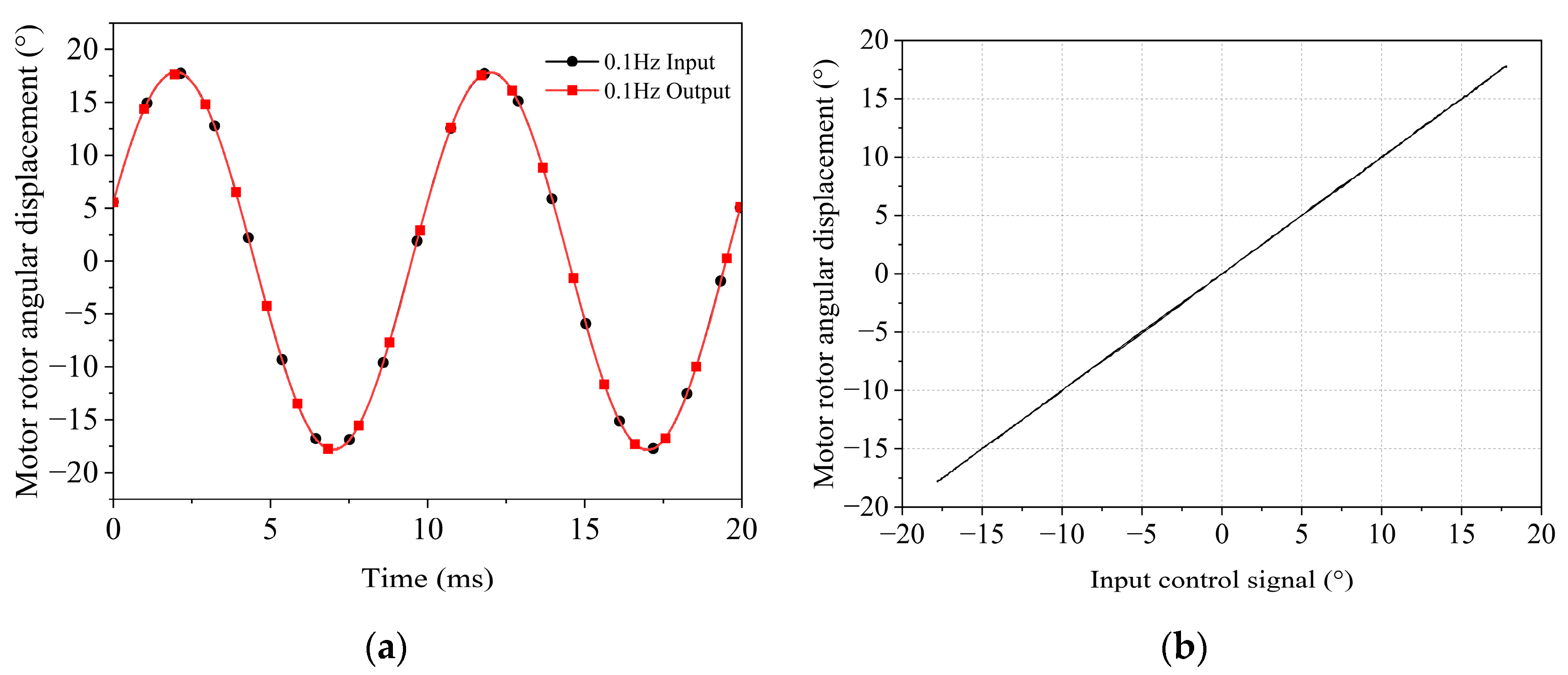
A sinusoidal signal with a frequency of 0.1 Hz and an amplitude of 17.75° was applied to the electro-mechanical converter to observe the tracking performance of its output displacement. As shown in Figure 12, a comparison of the input and output signals at 0.1 Hz indicated that the linearity of the input–output characteristics was 0.425% with negligible hysteresis.

5.2.2. Dynamic Characteristics of the Electro-Mechanical Converter

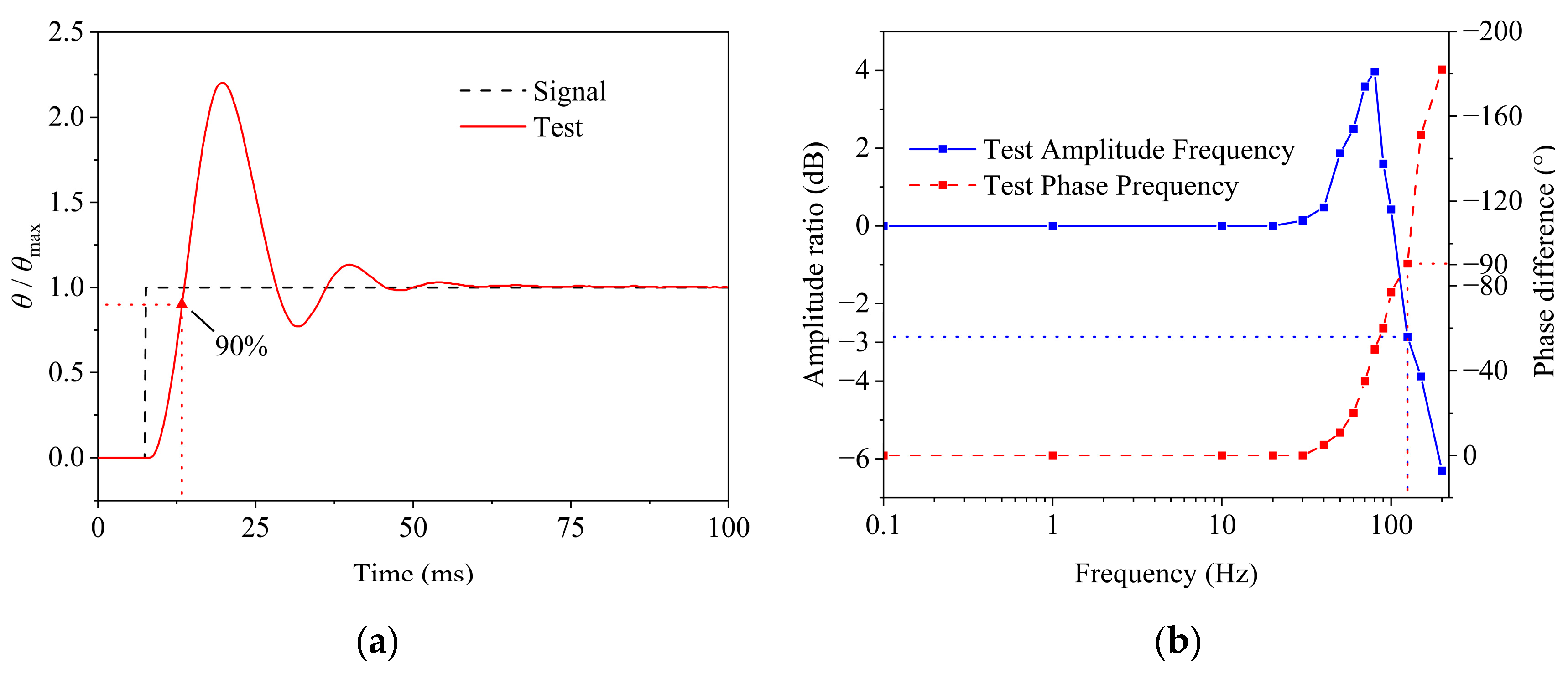
Figure 13a shows the step response of the electro-mechanical converter, with the black dashed line representing the input signal and the red solid line the output. The converter exhibited a response time of 5.6 ms and reached steady state within 50 ms. Figure 13b presents its Bode plot, including magnitude–frequency and phase–frequency curves. In the low-frequency range, the magnitude variation was minimal with a near-zero phase lag, indicating excellent tracking and low-latency performance. The magnitude curve rose sharply around 70 Hz, peaking at 100 Hz (resonance), and the −3 dB bandwidth was 130 Hz. The phase curve decayed significantly from 50 Hz onward, reaching a 90° lag at 125 Hz.

5.3. Static Characteristics of the Subminiature Two-Dimensional (2D) Electro-Hydraulic Servo Valve

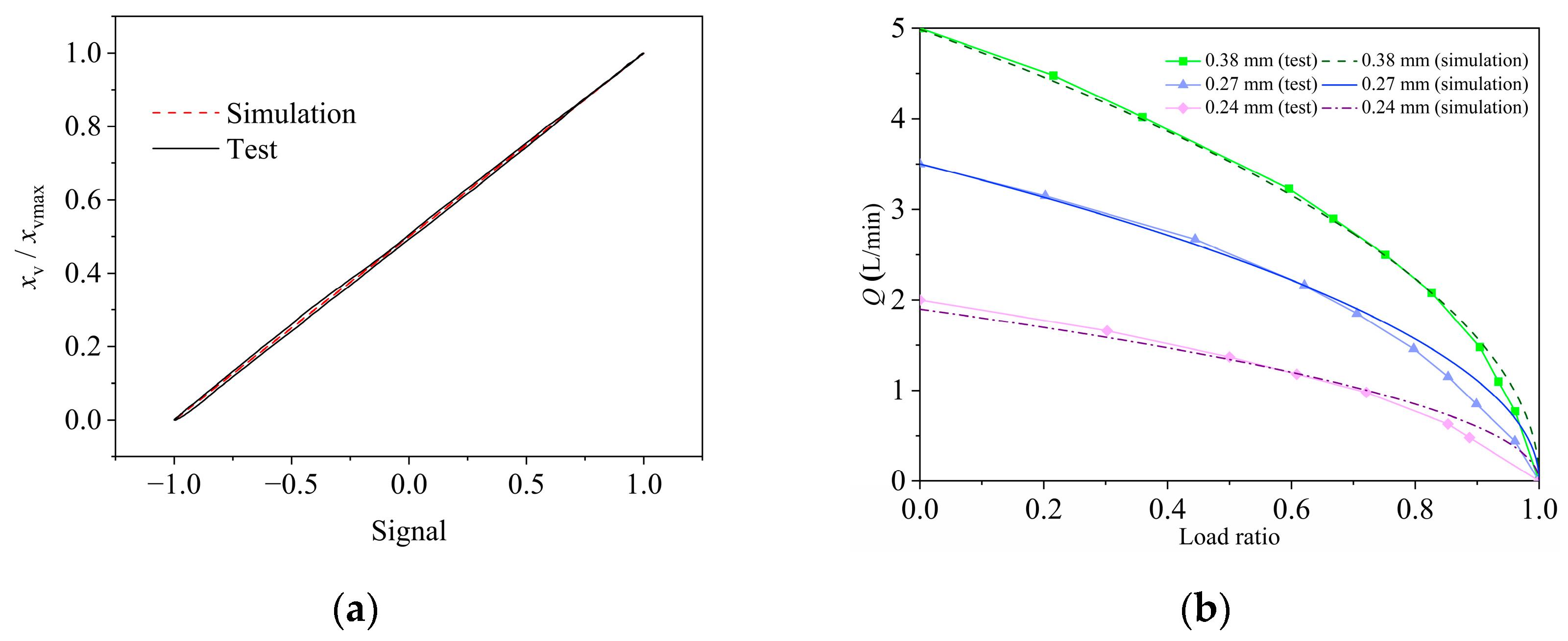
Figure 14a shows the hysteresis curve of the two-dimensional servo valve, and the measured hysteresis loop was 4.80% and the linearity was 2.54%, indicating that its servo screw mechanism had good linear characteristics. The difference between the experimental and simulation results may originate from the fact that the simulation model did not fully consider the static friction between the spool and the valve sleeve and the linearization of some parameters, or it may be that there were errors such as mating gaps, surplus, or runner cover in the actual manufacturing process, which introduced nonlinear factors.
Figure 14b compares the simulated and experimental load flow curves at a system pressure of 7 MPa. For a fixed spool displacement, the load flow rate decreased nonlinearly with increasing load pressure, indicating load-induced flow suppression. Conversely, an increasing spool displacement elevated the load flow rate, demonstrating spool position control over the valve port flow. The experimental curves from three tests aligned well with the simulations, with minor deviations likely due to prototype manufacturing tolerances and hydraulic circuit pressure losses.

5.4. Dynamic Characteristics of the Subminiature Two-Dimensional (2D) Electro-Hydraulic Servo Valve

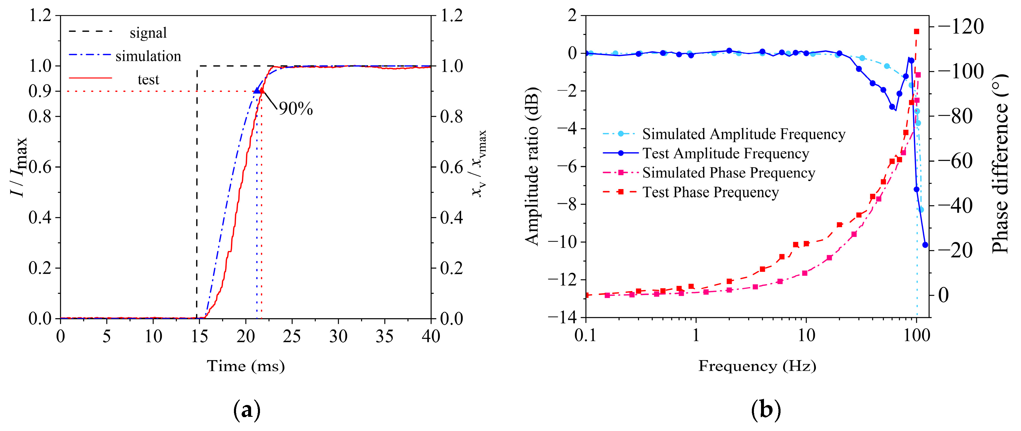
Figure 15a compares the step responses of the 2D servo valve prototype and simulations. At 7 MPa system pressure with a full-scale step input, the experimental response time was 7.5 ms, stabilizing at 8 ms without overshoot. Unlike the underdamped behavior of the electro-mechanical converter under no-load conditions, the 2D servo valve increased the system damping ratio under load, effectively suppressing oscillations and eliminating overshoot. The simulation matched the experimental trends, validating its dynamic response accuracy. The experimental results showed that there was a certain hysteresis in the dynamic response stage, which may be due to the fact that the simulation modeling did not fully consider the system pressure fluctuation, spool friction, and fluid damping and may also be due to the manufacturing tolerance resulting in the existence of micrometer-level masking between the spool and the valve sleeve, which in turn affects the actual response speed.
Figure 15b presents the experimental and simulated Bode plots (magnitude–frequency and phase–frequency curves). At 7 MPa supply pressure, the −3 dB magnitude bandwidths were 100 Hz (simulation) and 90 Hz (experiment), while the 90° phase lag frequencies were 100 Hz (simulation) and 95 Hz (experiment). These results confirm the valve’s superior dynamic–static performance and validate the co-simulation model’s utility in guiding physical prototype development.
Although there are differences between the simulation results and the experimental results, in general, the trend and change rule of the two were consistent, which indicates that the aforementioned joint simulation model can predict the frequency response characteristics of the system more accurately and provide a better technical basis for the development and validation of the prototype.
Table 4 compares the product weight and key performance parameters of the existing low-flow servo valves on the market with the servo valves developed in this paper.
The comparative data show that the market micro-servo valves generally have the problem of large weight, resulting in a low power-to-weight ratio; and in this design, through the optimization of the structure, the servo valve mass was successfully reduced to 73 g, which significantly improved the performance of the power-to-weight ratio.

6. Conclusions

(1)
This paper innovatively proposes a subminiature two-dimensional (2D) electro-hydraulic servo valve based on the servo helical mechanism, which realizes the integration of the pilot stage and the power stage by coupling the spool rotation and axial displacement double-degree-of-freedom motions and significantly improves the figure-of-merit-weight ratio. Meanwhile, a high-power-density brushless DC motor (BLDC) was adopted as the electro-mechanical converter to further reduce the volume and mass. Aiming at the special working conditions of the electro-mechanical converter with a small corner oscillation, a position–current double closed-loop PID control algorithm was designed on the basis of the FOC. The valve body was fabricated via binder jetting (BJ) additive manufacturing to reduce mass. The prototype dimensions were 31.7 mm × 29.3 mm × 31 mm, with a mass of 73 g.
(2)
A mathematical model of the electro-mechanical converter was developed, along with its control algorithm and transfer function. Stability conditions were derived using the Routh–Hurwitz criterion, showing that increasing the proportional gain, derivative gain, and damping coefficient or reducing the rotational inertia and integral gain, enhanced system stability, providing a theoretical basis for PID controller design. For the 2D servo spiral mechanism, mathematical modeling and transfer function derivation were performed. Stability analysis via the Routh–Hurwitz criterion indicated that increasing the inclination angle of the helical groove and high-pressure port radius improved stability, guiding structural design.
(3)
Co-simulation of the 2D servo valve was conducted using AMESim and Matlab/Simulink. The results indicate that under no-load conditions, the flow rate positively correlated with the system pressure, while under load, the flow rate negatively correlated with the load pressure ratio and exhibited nonlinear decay. The step response was overdamped with no overshoot or oscillation. Simulations also revealed that increasing the high-pressure port radius enhanced the response speed, whereas the inclination angle of the helical groove minimally affected the response speed but significantly altered steady-state flow.
(4)
An experimental platform was constructed to evaluate the dynamic and static performance of the 2D servo valve. The results demonstrated that the electro-mechanical converter had a response time of 5.6 ms, a −3 dB magnitude bandwidth of 130 Hz, and a phase bandwidth of 125 Hz; at 7 MPa, the valve achieved a maximum no-load flow rate of 5 L/min with 4.80% hysteresis and 2.54% linearity. The system step response time was 7.5 ms, with a −3 dB magnitude bandwidth of 90 Hz and a phase bandwidth of 95 Hz. The experimental data confirm the valve’s excellent dynamic–static performance.

Author Contributions

Conceptualization, L.P. and S.L.; methodology, L.P. and Q.D.; software, L.P. and C.Z.; validation, L.P., Q.D. and Z.S.; formal analysis, L.P. and Q.D.; investigation, L.P.; resources, S.L.; data curation, L.P.; writing—original draft preparation, L.P.; writing—review and editing, L.P.; visualization, L.P.; supervision, S.L.; project administration, S.L.; funding acquisition, S.L. All authors have read and agreed to the published version of the manuscript.

Funding

The research in this paper was funded by the National Key Research and Development Program of China (2019YFB2005201).

Data Availability Statement

Data are contained within the article.

Conflicts of Interest

The authors declare no conflict of interest.

Abbreviations

ParameterValue
u A , u B , u C Electro-mechanical converter winding terminal voltage
R A , R B , R C Three-phase winding resistance
i A , i B , i C Stator phase winding current
L Winding inductance constant
M Winding mutual inductance constant
T e Electro-mechanical converter electromagnetic torque
e A , e B , e C Three-phase stator reverse electromotive force
ω Rotor angular velocity
T L Load torque
J Electro-mechanical converter moment of inertia
B Damping factor
θ BLDC Electro-mechanical converter rotor electrical angle
R s Electro-mechanical converter internal resistance
L d Straight-axis inductors
L q Cross-axis inductors
ψ f Permanent magnet chain
P e Polar logarithm
K P p Position closed-loop proportional gain coefficient
K i p Position closed-loop integral gain coefficient
K d p Position closed-loop differential gain coefficient
Q 1 Flow into sensitive cavities
Q l 1 Leakage flow from high-pressure orifice to spiral groove
Q 2 Flow out of the sensitive cavity
Q l 2 Leakage flow from spiral groove to low-pressure hole
A s Sensitive cavity spool area
x v Spool displacement
V 1 Sensitive cavity volume
β e Volumetric modulus of elasticity of the oil
P c Sensitive cavity pressure
P s System pressure
h 1 Height of the overlap area of the high-pressure small hole and the servo spiral groove
h 0 Clearance from spiral groove to high-(low-) pressure hole
R Spool shoulder radius
β Spiral groove angle of rise
θ valve Spool angle
h 2 Height of the overlap area between the low-voltage small hole and the servo spiral groove
r d High-(low-) pressure hole radius
C d Flow rate trimming factor
A 1 Overlap area of high-pressure holes and servo helix grooves
ρ Fluid density
A 2 Overlap area between low-pressure hole and spiral groove
m Heavy mass of spool
B p Equivalent to the total viscosity coefficient on the valve spool
F L Load acting on the spool

References

  1. Yang, W.; Li, R.; Xu, J.; Xiao, G.; Yuan, W.; Sun, Y.; Zhang, Q. CFD-based axial steady-state hydrodynamic study and structural optimization of miniature switching valve. Flow Meas. Instrum. 2024, 100, 102744. [Google Scholar] [CrossRef]
  2. Simic, M.; Herakovic, N. Reduction of the flow forces in a small hydraulic seat valve as alternative approach to improve the valve characteristics. Energy Convers. Manag. 2015, 89, 708–718. [Google Scholar] [CrossRef]
  3. Bai, Y.; Yao, J.; Hu, J.; Feng, G. Output feedback active disturbance rejection control of an electro-hydraulic servo system based on command filter. Chin. J. Aeronaut. 2025, 38, 103169. [Google Scholar] [CrossRef]
  4. Zhao, J.; Luo, L.; Zhuo, Y.; Wang, M.; He, C.; Zhang, C.; Xie, G. Mechanical Characteristics and Miniaturization Design of the Electromagnetic Valve Used in Drilling Robots. Processes 2024, 12, 1685. [Google Scholar] [CrossRef]
  5. Liu, Y.; Wang, H.; Fan, Q. Adaptive learning and sliding mode control for a magnetic microrobot precision tracking with uncertainties. IEEE Robot. Autom. Lett. 2023, 8, 7767–7774. [Google Scholar] [CrossRef]
  6. Liu, Q.; Ghodrat, S.; Huisman, G.; Jansen, K.M.B. Shape Memory Alloy Actuators for Haptic Wearables: A Review. Mater. Des. 2023, 233, 112264. [Google Scholar] [CrossRef]
  7. Lisowski, E.; Filo, G.; Pluskowski, P.; Rajda, J. Flow analysis of a novel, three-way cartridge flow control valve. Appl. Sci. 2023, 13, 3719. [Google Scholar] [CrossRef]
  8. Xu, C.; Ren, Y.; Tang, H.; Lu, L.; Huang, Y.; Ruan, J. Investigation on a novel high frequency two-dimensional (2D) rotary valve variable mechanism for fluid pulse-width-modulation application. J. Mech. Sci. Technol. 2023, 37, 757–765. [Google Scholar] [CrossRef]
  9. Qun, F.; Zeng, H. Developing Process, Research Actuality and Trend of Electrohydraulic Servo valve. Mach. Tools Hydraul. 2007, 35, 162–165. [Google Scholar]
  10. Prsic, D.; Fragassa, C.; Nedic, N.; Pavlovic, A. Describing function of the pneumatic flapper-nozzle valve. Mech. Syst. Signal Process. 2019, 124, 696–714. [Google Scholar] [CrossRef]
  11. Yan, H.; Wang, F.-J.; Li, C.-C.; Huang, J. Research on the jet characteristics of the deflector–jet mechanism of the servo valve. Chin. Phys. B 2017, 26, 044701. [Google Scholar] [CrossRef]
  12. Li, C.; Yin, Y.; Wang, M.; Wang, F. Influence of high temperature on couples matching and characteristics of jet pipe electrohydraulic servovalve. J. Mech. Eng. 2018, 54, 251–261. [Google Scholar] [CrossRef]
  13. Chu, Y.; Yuan, Z.; He, X.; Dong, Z. Model construction and performance degradation characteristics of a deflector jet pressure servo valve under the condition of oil contamination. Int. J. Aerosp. Eng. 2021, 2021, 8840084. [Google Scholar] [CrossRef]
  14. Zhao, R.; Liao, Y.; Lian, Z.; Li, R.; Guo, Y. Research on the performance of a novel electro-hydraulic proportional directional valve with position-feedback groove. Proc. Inst. Mech. Eng. Part E J. Process Mech. Eng. 2021, 235, 1930–1944. [Google Scholar] [CrossRef]
  15. Zhang, J.; Yang, M.; Xu, B. Design and experimental research of a miniature digital hydraulic valve. Micromachines 2018, 9, 283. [Google Scholar] [CrossRef]
  16. Obayashi, H.; Akagi, T.; Dohta, S.; Kobayashi, W.; Matsui, Y.; Shimooka, S.; Shinohara, T.; Aliff, M. Development of portable rehabilitation device driven by low-cost servo valve using tap water. Int. J. Mech. Eng. Robot. Res. 2020, 9, 353–359. [Google Scholar] [CrossRef]
  17. Yan, L. Multi-Parameter Comprehensive Influence Mechanism and Experimental Research on Zero Position Characteristics of Jet Disk Servo Valve. Master’s Thesis, Harbin Institute of Technology, Harbin, China, 2020. [Google Scholar]
  18. Bai, J. Research on Control Key Technology of Resonant Electro-Hydraulic High-Frequency Fatigue Testing Machine. Ph.D. Thesis, Zhejiang University of Technology, Harbin, China, 2013. [Google Scholar]
  19. Bing, M.; Qiong, L. Torque-angle Characteristics of Permanent Magnet Torque Motor with Single-phase Excitation. Mech. Sci. Technol. Aerosp. Eng. 2018, 37, 532–536. [Google Scholar] [CrossRef]
  20. Yu, Y.; Ke, S.; Jin, K. Structural parameters optimization for a proportional solenoid. Int. J. Simul. Model. 2020, 19, 689–700. [Google Scholar] [CrossRef]
  21. Yokota, S.; Hiramoto, K. An ultra high-speed electrohydraulic servo valve by making use of a multilayered piezoelectric device (PZT). Compensation of the hysteresis by introducing a software algorithm. Nihon Kikai Gakkai Ronbunshu B Hen/Trans. Jpn. Soc. Mech. Eng. Part B 1991, 57, 182–187. [Google Scholar] [CrossRef]
  22. Zhou, X.; Wu, S.; Wang, X.; Wang, Z.; Zhu, Q.; Sun, J.; Huang, P.; Wang, X.; Huang, W.; Lu, Q. Review on piezoelectric actuators: Materials, classifications, applications, and recent trends. Front. Mech. Eng. 2024, 19, 6. [Google Scholar] [CrossRef]
  23. Sheng, L. Research of Key Technologies of Digital Control for 2D Servo Valve. Ph.D. Thesis, Zhejiang University of Technology, Harbin, China, 2012. [Google Scholar]
  24. Mohanraj, D.; Aruldavid, R.; Verma, R.; Sathiyasekar, K.; Barnawi, A.B.; Chokkalingam, B.; Mihet-Popa, L. A review of BLDC motor: State of art, advanced control techniques, and applications. IEEE Access 2022, 10, 54833–54869. [Google Scholar] [CrossRef]
  25. Ruan, J.; Burton, R.; Ukrainetz, P. An Investigation into the Characteristics of a Two Dimensional “2D” Flow Control Valve. J. Dyn. Syst. Meas. Control 2002, 124, 214–220. [Google Scholar] [CrossRef]
  26. Zhao, C.; Cai, J.; Zhang, B.; Qu, X. Key technology of binder jet 3D printing. J. Mater. Eng. 2023, 51, 14–26. [Google Scholar]
  27. Mostafaei, A.; Elliott, A.M.; Barnes, J.E.; Li, F.; Tan, W.; Cramer, C.L.; Nandwana, P.; Chmielus, M. Binder Jet 3D Printing—Process Parameters, Materials, Properties, Modeling, and Challenges. Prog. Mater. Sci. 2021, 119, 100707. [Google Scholar] [CrossRef]
  28. Chen, W.; Zhang, L.; Dong, Z.; Yang, Z.; Li, T. Research on Low-cost Tungsten Powder Printing Process Using Binder Jet 3D Printing. Mater. Her. 2024, 38, 387–390. [Google Scholar]
  29. Wang, H.; Chau, K.; Liu, W.; Goetz, S.M. Design and control of wireless permanent-magnet brushless DC motors. IEEE Trans. Energy Convers. 2023, 38, 2969–2979. [Google Scholar] [CrossRef]
  30. Skuric, A.; Bank, H.S.; Unger, R.; Williams, O.; González-Reyes, D. SimpleFOC: A field oriented control (FOC) library for controlling brushless direct current (BLDC) and stepper motors. J. Open Source Softw. 2022, 7, 4232.123. [Google Scholar] [CrossRef]
  31. Hussein, T.A.; Mohammed, L.A. Detailed Simulink implementation for induction motor control based on space vector pulse width modulation SVPWM. Indones. J. Electr. Eng. Comput. Sci. 2021, 22, 1251–1262. [Google Scholar]
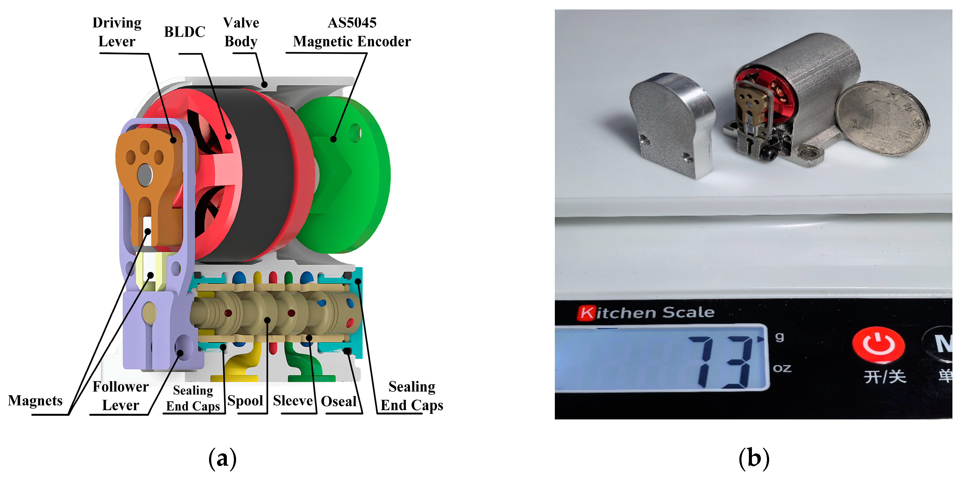
Figure 1. A subminiature two-dimensional (2D) electro-hydraulic servo valve. (a) Schematic diagram of the 2D servo valve structure; (b) prototype of the 2D servo valve.
Machines 13 00388 g001
Figure 2. Working principle diagram of the 2D servo screw mechanism: (a) forward movement of the 2D servo screw mechanism; (b) reverse movement of the 2D servo screw mechanism.
Machines 13 00388 g002
Figure 3. Control algorithm block diagram of the electro-mechanical converter.
Machines 13 00388 g003
Figure 4. Control block diagram of the subminiature two-dimensional (2D) electro-hydraulic servo valve.
Machines 13 00388 g004
Figure 5. Geometric relationship diagram of the servo screw mechanism.
Machines 13 00388 g005
Figure 6. Closed-loop control block diagram of the servo screw mechanism.
Machines 13 00388 g006
Figure 7. Simulation model of the control algorithm for the electro-mechanical converter.
Machines 13 00388 g007
Figure 8. Combined simulation model of the subminiature two-dimensional (2D) electro-hydraulic servo valve.
Machines 13 00388 g008
Figure 9. Static characteristics: (a) no-load flow characteristics; (b) load flow characteristics.
Machines 13 00388 g009
Figure 10. Dynamic characteristic simulation: (a) high-pressure hole radius ( r d ); (b) slot tilt angle ( β ).
Machines 13 00388 g010
Figure 11. Subminiature two-dimensional (2D) electro-hydraulic servo valve system test bench: (a) schematic diagram of the small 2D servo valve system test bench; (b) physical diagram of the small 2D servo valve system test bench. 1—pump station; 2—relief valve; 3, 7, 8, 11, 12, 15, 16—switch valves; 4, 6, 10, 13—pressure gauges; 5, 14—flow meters; 9—valve under test.
Machines 13 00388 g011
Figure 12. Static characteristic curve of the electro-mechanical converter: (a) 0.1 Hz tracking curve of the electro-mechanical converter; (b) hysteresis curve of the electro-mechanical converter.
Machines 13 00388 g012
Figure 13. Dynamic characteristic curve of the electro-mechanical converter: (a) step response curve of the electro-mechanical converter; (b) frequency response curve of the electro-mechanical converter.
Machines 13 00388 g013
Figure 14. Static characteristic curve of the subminiature two-dimensional (2D) electro-hydraulic servo valve: (a) hysteresis curve of the 2D servo valve; (b) load flow characteristic curve of the 2D servo valve.
Machines 13 00388 g014
Figure 15. Dynamic response curve of the subminiature 2D servo valve: (a) step response curve of the subminiature two-dimensional (2D) electro-hydraulic servo valve; (b) frequency response curve of the subminiature two-dimensional (2D) electro-hydraulic servo valve.
Machines 13 00388 g015
Table 1. Parameters of the electro-mechanical converter.
Pole PairsMass/kgResistance/ΩDirect Axis Inductance Ld/μHQuadrature Axis Inductance Lq/μHFlux Linkage Coefficient /WbRotational Inertia J/g·cm2
60.0150.1575.42419.50.00077283.57
Table 2. Simulation parameters.
ModuleParametersValue
Master valveSpool diameter/mm4.5
Spool mass/g2
Inclination angle of slanting groove/°83.4
High-pressure hole diameter/mm1
Spool displacement/mm±0.9
Flow rate coefficient0.62
Offset distance e /mm1.8
FluidsFluid density/(kg×m−3)860
Bulk modulus of elasticity/MPa700
Fluid system pressure/MPa7
Table 3. Model and parameters of the instrument used.
ComponentModel NumberParameters
Flow meterA350-AO0–40.00 L/min
OscillographMSO-X 3054AMaximum sampling frequency: 500 MHz
Laser displacement sensorLK-G150650 nm
Signal generators33660A
Table 4. Comparison of the parameters of each valve on the market.
ManufacturerSeries ModelLinearityMassBandwidth
MOOGMOOG73<±71180>80
REXRITH4WS2EM<±10800>80
PARKER BD062<±102100>18
This article2D servo valve2.547390
Disclaimer/Publisher’s Note: The statements, opinions and data contained in all publications are solely those of the individual author(s) and contributor(s) and not of MDPI and/or the editor(s). MDPI and/or the editor(s) disclaim responsibility for any injury to people or property resulting from any ideas, methods, instructions or products referred to in the content.