Article

Numerical Simulation of Aerodynamic Characteristics of Trailing Edge Flaps for FFA-W3-241 Wind Turbine Airfoil

1
School of Energy and Power Engineering, Nanjing Institute of Technology, Nanjing 211167, China
2
Jiangsu Key Laboratory of High Technical Research of Wind Turbine Design, Nanjing University of Aeronautics and Astronautics, Nanjing 210016, China
*
Authors to whom correspondence should be addressed.
Machines 2025, 13(5), 366; https://doi.org/10.3390/machines13050366
Submission received: 1 April 2025 / Revised: 25 April 2025 / Accepted: 28 April 2025 / Published: 29 April 2025
(This article belongs to the Special Issue Cutting-Edge Applications of Wind Turbine Aerodynamics)

Abstract

The blades of wind turbines constitute key components for converting wind energy into electrical energy, and modifications to blade airfoil geometry can effectively enhance aerodynamic performance of wind turbine. The trailing edge flap enables load control on the blades through adjustments of its motion and geometric parameters, thereby overcoming limitations inherent in conventional pitch control systems. However, current research primarily emphasizes isolated parametric effects on airfoil performance, with limited exploration of interactions between multiple design variables. This study adopts a numerical simulation approach based on the FFA-W3-241 airfoil of the DTU 10 MW. Geometric deformations are achieved by manipulating flap parameters, and the influence on airfoil aerodynamic performance is analyzed using computational fluid dynamics methods. Investigations are conducted into the effects of flap lengths and deflection angles on airfoil aerodynamic characteristics. The results show the existence of an optimal flap length and deflection angle combination. Specifically, when the flap length is 0.1 c and the deflection angle is 10°, the lift-to-drag ratio demonstrates significant improvement under defined operational conditions. These findings offer practical guidance for optimizing wind turbine airfoil designs.

1. Introduction

The ecological and environmental crisis is becoming increasingly severe, the vigorous development of wind power has emerged as a global consensus [1]. To enhance wind energy utilization efficiency, nations worldwide are committed to promoting the upgrade and development of wind power generation technology. Among critical components of wind turbines, wind turbine blades play a pivotal role in converting wind energy into electrical power, with multiple methods currently available to effectively enhance the aerodynamic performance of blades. Trailing edge flaps, as a common and effective lift-increasing device, have attracted widespread attention due to their simple structure and ease of installation [2]. During wind turbine operation, the trailing edge flap will modify the aerodynamic performance, achieve load control, and mitigate the limitations of conventional pitch control technology, such as large inertia and ineffective regulation of local load fluctuations [3,4].
The application of flap technology in wind turbines has its origins in helicopter rotor flap technology. However, during actual operation, wind turbines experience unsteady flow conditions, including wind shear, yaw misalignment, rotor angle variations, and variable speed or pitch control strategies [5], which significantly induce non-uniform and non-periodic aerodynamic load characteristics. Consequently, dedicated research is required to investigate the mechanisms of variable trailing edge flaps for wind turbine blades. Several well-known laboratories [6,7,8] have previously recognized the potential of trailing edge flaps for wind turbine blades and initiated systematic investigations. Initial findings demonstrate that trailing edge flaps provide substantial load alleviation under complex inflow conditions [3].
The deformation mode of variable flaps significantly influences aerodynamic performance. Trailing edge flaps exhibit two primary deformation configurations: flexible flaps and segmented rigid flaps. Research indicated that flexible trailing edge flaps maintain a continuous shape, which is not easy to cause flow separation, and have better aerodynamic characteristics and load alleviation capabilities [9]. However, the complex structure makes it difficult to achieve variable angle-of-attack control. The segmented rigid flaps offer straightforward control logic and rapid response, which can assist the pitch system to make fine adjustments. But, it is inevitable that there will be a gap between flap segments and the main airfoil, which will affect the lift and drag characteristics [10]. Several scholars have studied the influence of geometry parameters of trailing edge flaps on aerodynamic performance for airfoils such as Risø-B1-18 [11,12], DU96-W180 [13], NACA0015 [14,15], and S809 [16,17] using experiments and numerical calculations. The results confirm that deflecting flaps toward the pressure side enhances lift coefficients. By adjusting the length and deflection angle of the flaps, it is possible to achieve good comprehensive aerodynamic performance within a certain range of angles of attack and effectively reduce pulsation loads over a wide frequency range [9].
The relative relationship between the flap motion mechanism and the variation in the angle of attack has a significant impact on the aerodynamic performance and load reduction effect. Troldborg [12] studied the variation in aerodynamic performance of Risø-B1-18 airfoil under different flap motion conditions, providing foundational insights for subsequent research. Wolff et al. [13] found that, when flaps deviate significantly at the high pitch angle, the lift variation pattern opposes conventional lift hysteresis phenomenon. The amplitude of the airfoil lift variation decreases as the frequency of airfoil pitch or flap deflection motion increases. Li et al. [18] analyzed the influence of different flap deflection mechanisms on the S809 airfoil at a fixed angle of attack, noting that as flap deflection frequency increases, both the lift hysteresis phase difference and fluctuation amplitude initially rise before subsequently declining. Hao et al. [19,20] demonstrated that under fixed angle of attack conditions, dynamic load amplitude during mild stall exceeds that in deep stall states, attributing this to flap motion induced pressure redistribution on the airfoil’s front surface, though flow development evidence remains lacking. Seyednia et al. [21,22] investigated the influence of flap motion frequency on the dynamic pitch aerodynamic performance of the NACA64 airfoil. The study demonstrated that asynchronous coupling motion of flap and airfoil at the same frequency can significantly reduce the dynamic loads. At this operational condition, increasing flap length was shown to reduce the lift ring slope and facilitate load reduction implementation. When the flap motion frequency exceeds airfoil motion frequency, load reduction does not occur. The traditional body-fitted grid technique is not conducive to implementing large deformation motions, which constitutes a critical limitation in studying trailing edge flap dynamic stall flow control mechanisms. Zhu et al. [23] proposed a hybrid method combining body-fitted grids with the immersed boundary method, providing a novel computational fluid dynamics (CFD) research approach. However, this method still requires grid refinement in solid wall interaction zones for accurate boundary layer flow simulation, which restricts flap deflection angles. Its broader application remains to be further explored. Liu et al. [24] studied trailing edge flap aerodynamic noise of vertical axis wind turbines and proposed a flap control method. Zhuang et al. [25] investigated the effects of various morphed trailing edge flaps on the airfoil aerodynamic characteristics and analyzed the increase in lift coefficient. Arredondo et al. [26] reduced the unsteady airfoil load by adding foil to the trailing edge flaps and conducted water tunnel experiments to verify the results. Mancini et al. [27] carried out experimental research on the aerodynamic characteristics of trailing edge flaps with 50% chord length and analyzed their trailing edge flow. He et al. [28] performed pitch characteristic experiments on NACA0015 with oscillating trailing edge flaps and analyzed the effect of flaps on the dynamic airflow velocity. Tian et al. [29] studied a novel energy harvester with trailing edge flaps, which can enhance its energy output characteristics. Rivero et al. [30] investigated the lift enhancement of the morphed trailing edge flap on the airfoil section based on experimental method and found that the lift can be increased by more than 50%. Watkins et al. [31] studied the aerodynamic noise reduction of 30P30N airfoil under different flap angles and found that noise can be reduced by 11% under specific conditions Haldar et al. [32] proposed a novel morphed trailing edge flap that enables rapid deformation of the trailing edge flaps. Ameduri et al. [33] analyzed the design method of the morphed trailing edge flap and studied aviation performance improvements.
The above studies have explored the influence of trailing edge flaps on aerodynamic performance and the load reduction effect from different perspectives, establishing a foundational understanding. Currently, the FFA-W3-241 airfoil is adopted in the 20 MW wind turbine. However, research on trailing edge flaps for this airfoil remains relatively rare. Existing analyses have predominantly focused on isolated effects of single or limited parameters, and the various effects among parameters on aerodynamic performance have not been further explored [34]. In this paper, the FFA-W3-241 airfoil is taken as the basic airfoil, and the geometrical deformation is realized by controlling the flap parameters. The influence of different flap deformations is investigated by using CFD methods. The aerodynamic laws are summarized, and the optimal flap configuration is obtained. The main contribution of this paper is to investigate the application of trailing edge flaps in the FFA-W3-241 airfoil and to analyze their effectiveness. The effects of different combinations of trailing edge flap parameters on aerodynamic performance are systematically analyzed. The optimal trailing edge flap configuration for the FFA-W3-241 airfoil under the calculated conditions is identified.

2. Calculation Model

2.1. Basic Airfoil Geometry

The FFA series airfoil, designed specifically for wind turbines, represents a new generation of wind turbine airfoils. Its maximum relative thickness varies between 12.8% and 36%. This series of airfoils is not easily affected by leading edge roughness and has excellent aerodynamic performance and stability. Among them, the FFA-W3 series airfoil has great potential for development and application in future wind power generation equipment due to its high lift-to-drag ratio, as well as its ability to maintain good aerodynamic performance under stall conditions [35]. In this paper, the FFA-W3-241 airfoil is selected as the research object. Figure 1 illustrates the basic geometry of the FFA-W3-241 airfoil.

2.2. Trailing Edge Flaps Model

In order to minimize the design variables in optimization design, the airfoil parameterization method is often used to reconstruct the aerodynamic shape [4]. In this paper, the airfoil chord length c is set to 1000 mm and two structural parameters are introduced: flap length b and flap deflection angle β . The geometrical characteristics and influence laws of the variable trailing edge flap motion mechanism are quantitatively analyzed and summarized.
The geometric deformation function expression for a static trailing edge flap is given:
Δ y ( x ) = l f ( x x h p l f ) N tan ( β ) ,
where l f is the flap length, x is the chordwise position from the rotation center, and x h p is x-coordinate of the anchor point. N is the smoothness of the flap deflection. in this paper, a smoother flexible deformation is used, taking N = 2. The flap deflection angle is defined as positive when deflecting downward. The specific morphology of different deflection angles is shown in Figure 2.

2.3. Numerical Method

In the process of using CFD to solve aerodynamic characteristics of airfoil, it is necessary to mesh the fluid domain. The computational fluid domain grid adopts a structured grid. Due to the excessive curvature when the trailing edge flap deflects downward by 10°, a C-type grid is selected for the airfoil. The airfoil grid is shown in Figure 3. The boundary of the calculation domain is set to be 10 times the chord length from the airfoil. The boundary conditions are set as velocity inlet and pressure outlet, while the airfoil surface is a no-slip wall boundary condition. The height of the first layer grid from the airfoil is less than 10−6 m, ensuring that y + < 1.
The transition phenomenon in the boundary layer of an airfoil or blade surface, which has a significant impact on the simulation accuracy of the aerodynamic characteristics of the blade. Most turbulence models are full turbulence models, while the Transition SST model considers the airflow transition on the airfoil surface and maintains laminar flow at the leading edge, which makes it a common choice for turbulence simulation in wind turbine aerodynamic analysis [4], as it captures the transition effects. Therefore, the Transition SST model is selected in this paper to determine the aerodynamic performance parameters and flow field of the airfoil.
The flow field calculation conditions listed in Table 1 are selected when investigating the influence of trailing edge flaps on the aerodynamic characteristics of wind turbine airfoils.

3. Grid Independence Verification

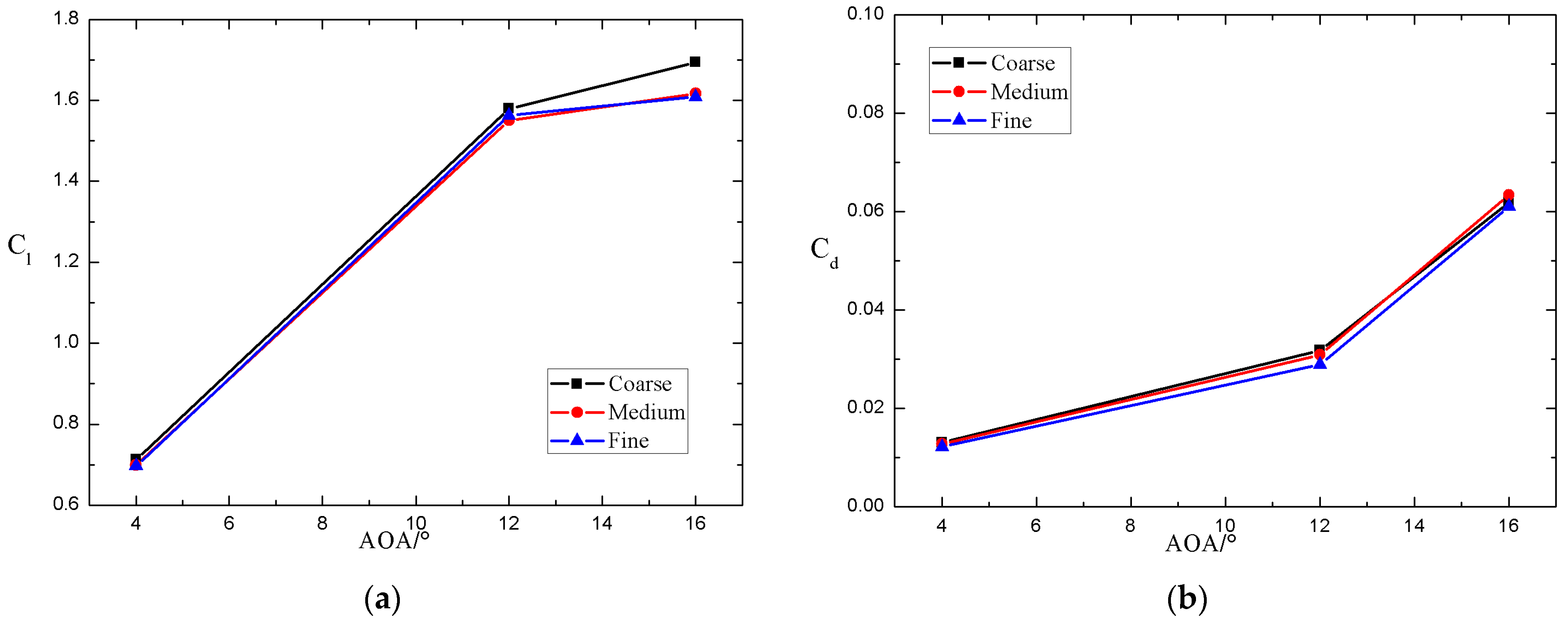
The FFA-W3 series airfoils are wind turbine specific airfoils with blunt trailing edges. In order to generate high quality grids without excessive grid distortion, the flow field contour must align with the airfoil profile. In numerical simulations, the fineness of the grid significantly affects the accuracy of the results. To ensure the reliability of simulation results, grid independence verification is required [36]. This process helps determine the optimal grid size, ensuring that the simulation results are both accurate and efficient. In this paper, three computational grids with different grid numbers are generated, namely coarse grid, medium grid, and fine grid, to evaluate the influence of grid number on the simulation results. The specific calculation results are shown in Figure 4 and Table 2.
The results of the fine grid and medium grid are basically consistent, but there is a significant difference in the total number of grids between the two schemes. While the coarse grid scheme utilizes fewer grids, it differs significantly from the fine grid scheme at large angles of attack. However, a greater number of grids does not necessarily ensure more accurate results, as accuracy is also influenced by the shape and distribution of the grids. Taking into account both the calculation time and accuracy requirements, this paper conducts further simulations based on the medium grid scheme.

4. Experimental Verification

To verify the accuracy of the numerical simulation method proposed, the aerodynamic characteristics experimental data of the FFA-W3-241 airfoil are used to validate the numerical simulation results. The experimental data are obtained from wind tunnel experiments conducted at the Risø National Laboratory in the VELUX wind tunnel, with an experimental Reynolds number of 1.6 × 10⁶ based on the free-stream velocity. Due to the absence of experimental results for flap deflection configurations, comparisons are primarily focused on the configuration without flap deflection. Additionally, the calculation results are compared with other numerical simulations, including those from XFOIL and Ellipsys2D. As shown in Figure 5, the present study’s results agree well with experimental data below 10° angle of attack, whereas XFOIL and Ellipsys2D slightly overestimate the lift coefficient. In terms of maximum lift coefficient, the current results demonstrate better agreement with experimental values than other software. For drag coefficient, XFOIL and Ellipsys2D underestimate the values, while the present calculations showed closer alignment with experimental measurements.
In summary, the results indicate that the calculation results presented show good consistency with the experimental results, demonstrating sufficient accuracy. Therefore, the proposed numerical simulation method can be utilized to investigate the effects of different trailing edge flaps.

5. Calculation Results and Analysis

In this paper, calculations are performed to investigate the impact of flap length and deflection angle on the aerodynamic characteristics of the FFA-W3-241 airfoil. The quantitative variation laws of the lift and drag coefficient as functions of flap length and deflection angle are derived.

5.1. Influence of Flap Deflection Angle

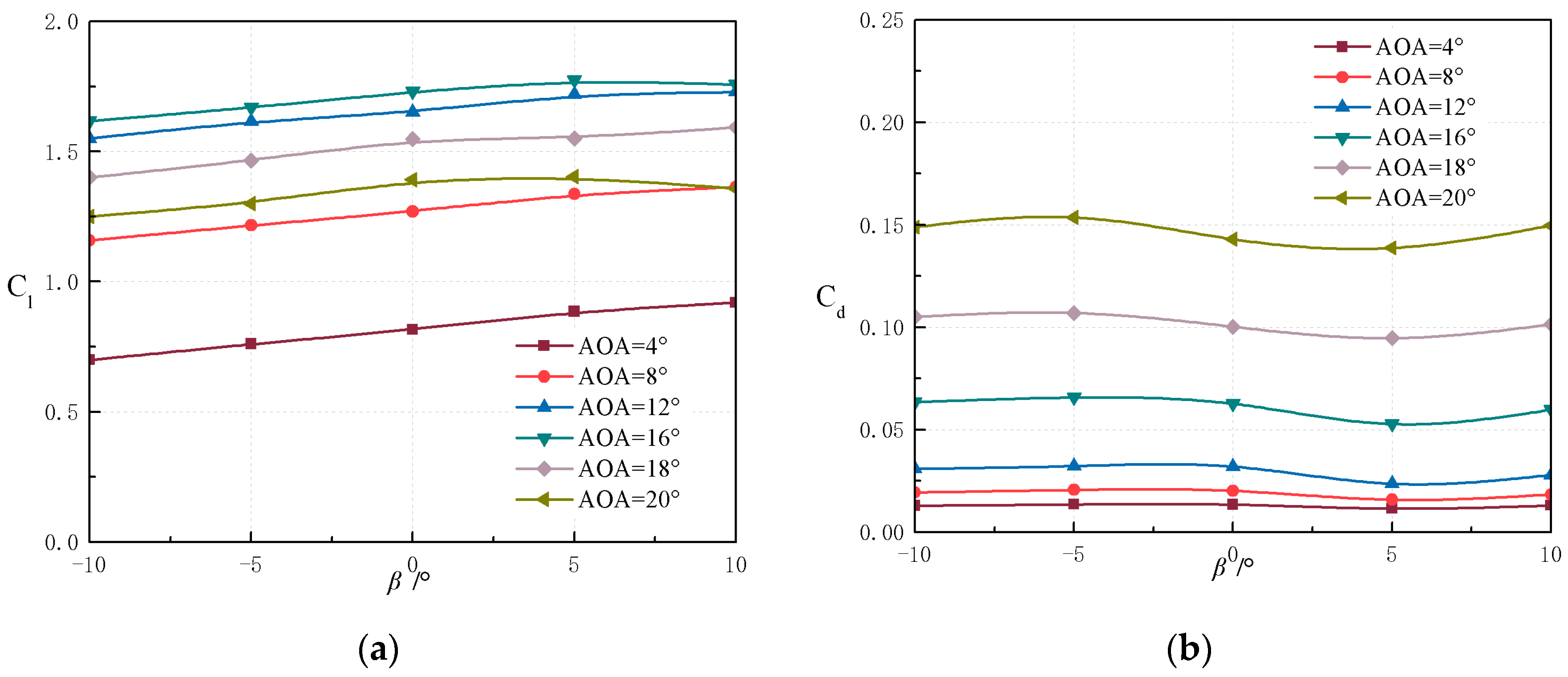
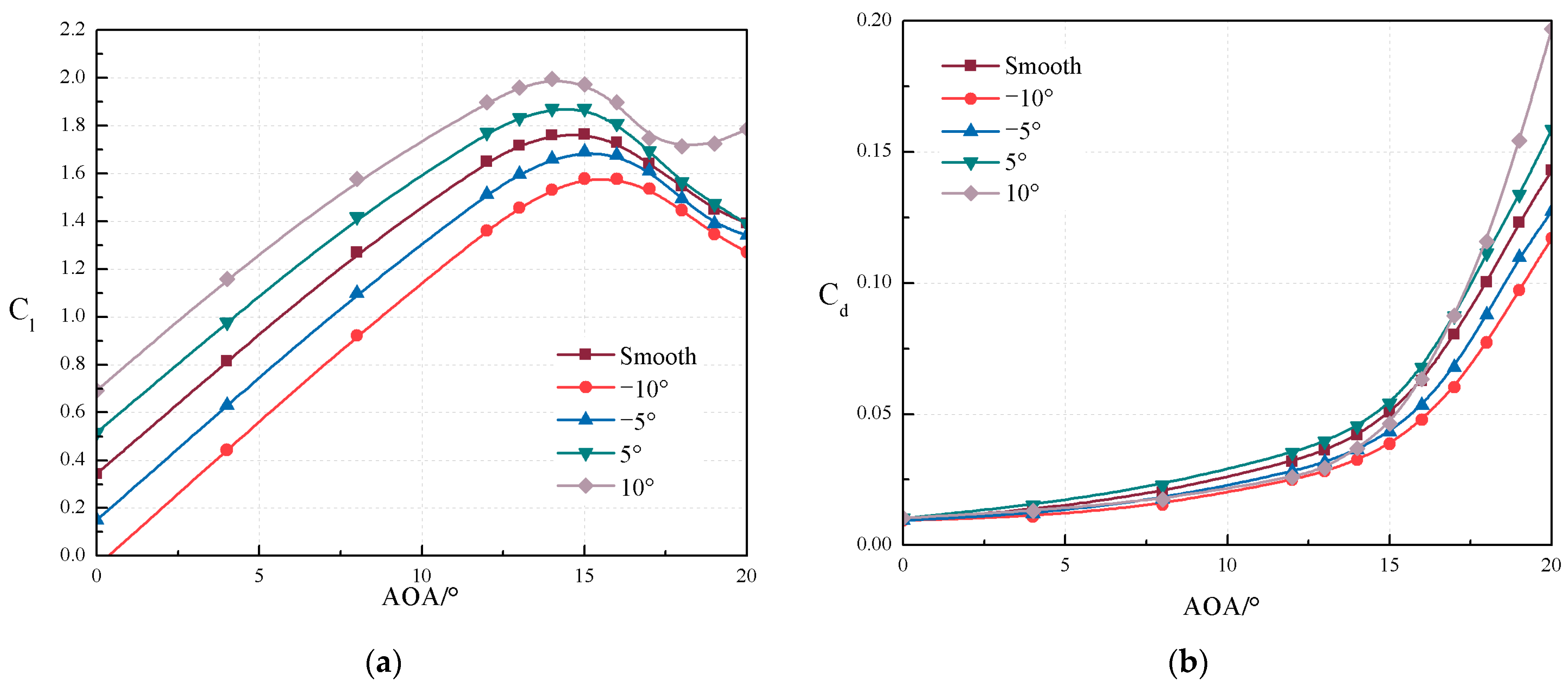
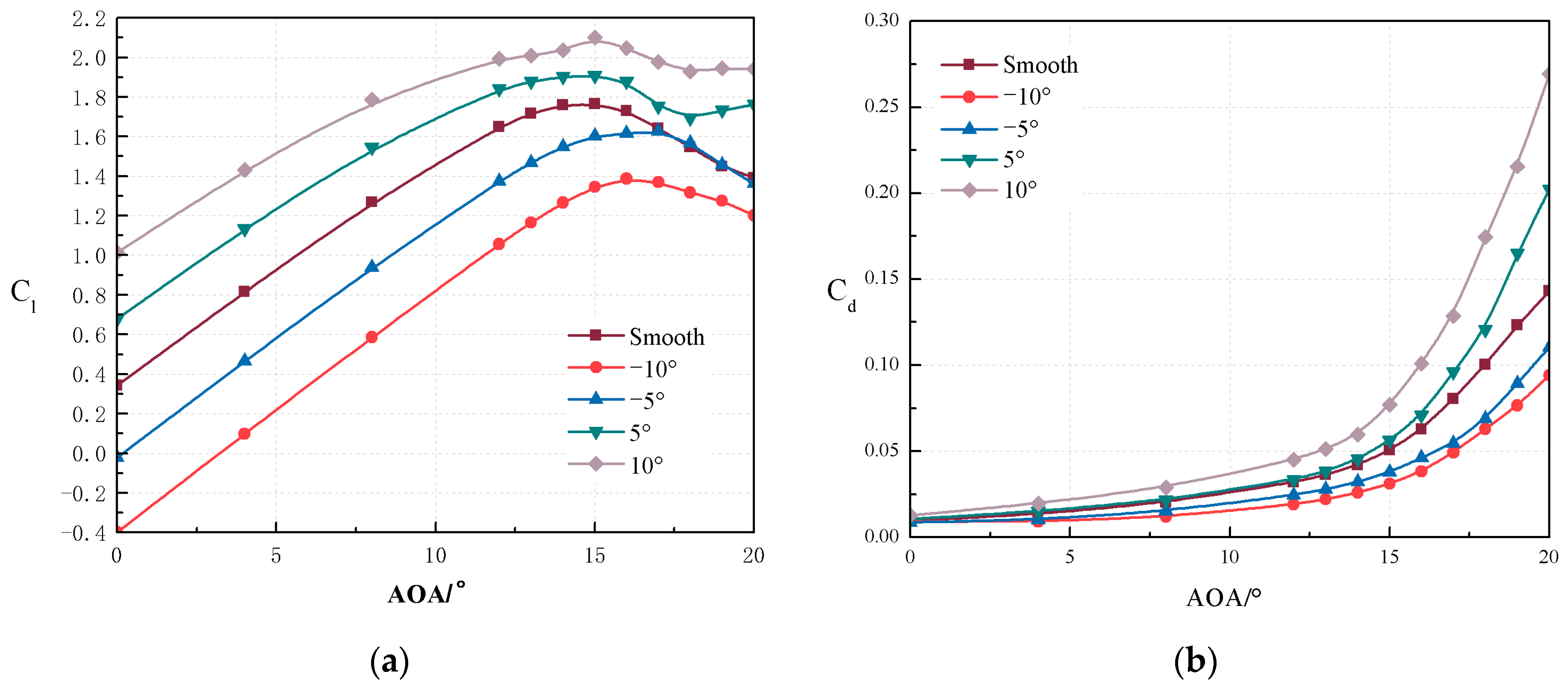
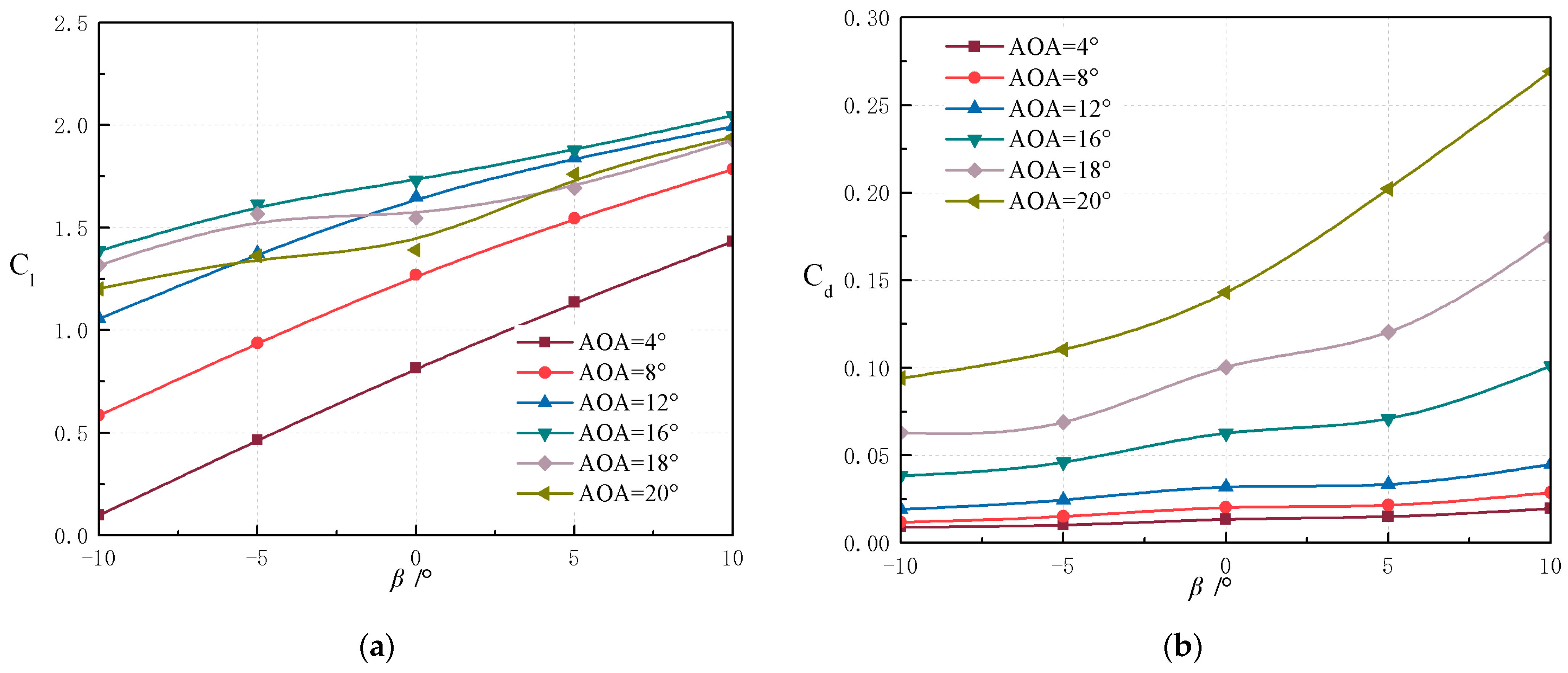
Figure 6 shows the influence of flap deflection angle on the lift and drag characteristics of the airfoil when the flap length is 0.1 c . The results demonstrate that downward deflection of the flap significantly improves the lift coefficient. As shown in Figure 7, the change in lift caused by flap deflection at small angles of attack is greater than those at large angles of attack. At small angles of attack, the increase in lift coefficient corresponds with the downward deflection of the flap. Conversely, the lift coefficient gradually decreases when the flap is deflected upward. When the angle of attack exceeds the linear region, the effect of the flap weakens gradually. C l / β represents the sensitivity of lift coefficient to flap deflection angle, which decreases with increasing angle of attack. From C l / β α = 4 ° 0.011 , gradually decrease to C l / β α = 12 ° 0.010 , and finally decrease to C l / β α = 18 ° 0.096 . The flap effective parameter η f l a p also can be used to measure
η f l a g = C l / β C l / α ,
For α = 10 ° , η f l a p 0.327 . This implies that the increment in lift coefficient caused by Δ α = 1 ° can be offset by the contribution of a 3° upward flap deflection.
For drag coefficient prediction, a positive deflection of trailing edge flap leads to an increase in the drag coefficient, while a negative deflection leads to a decrease in drag. In contrast to the lift coefficient curve, the sensitivity of drag coefficient to flap deflection angle shows a significant change as it increases with increasing angle of attack. It gradually increases from a smaller angle of attack C d / β α = 4 ° 0.000376 to C d / β α = 16 ° 0.000448 .
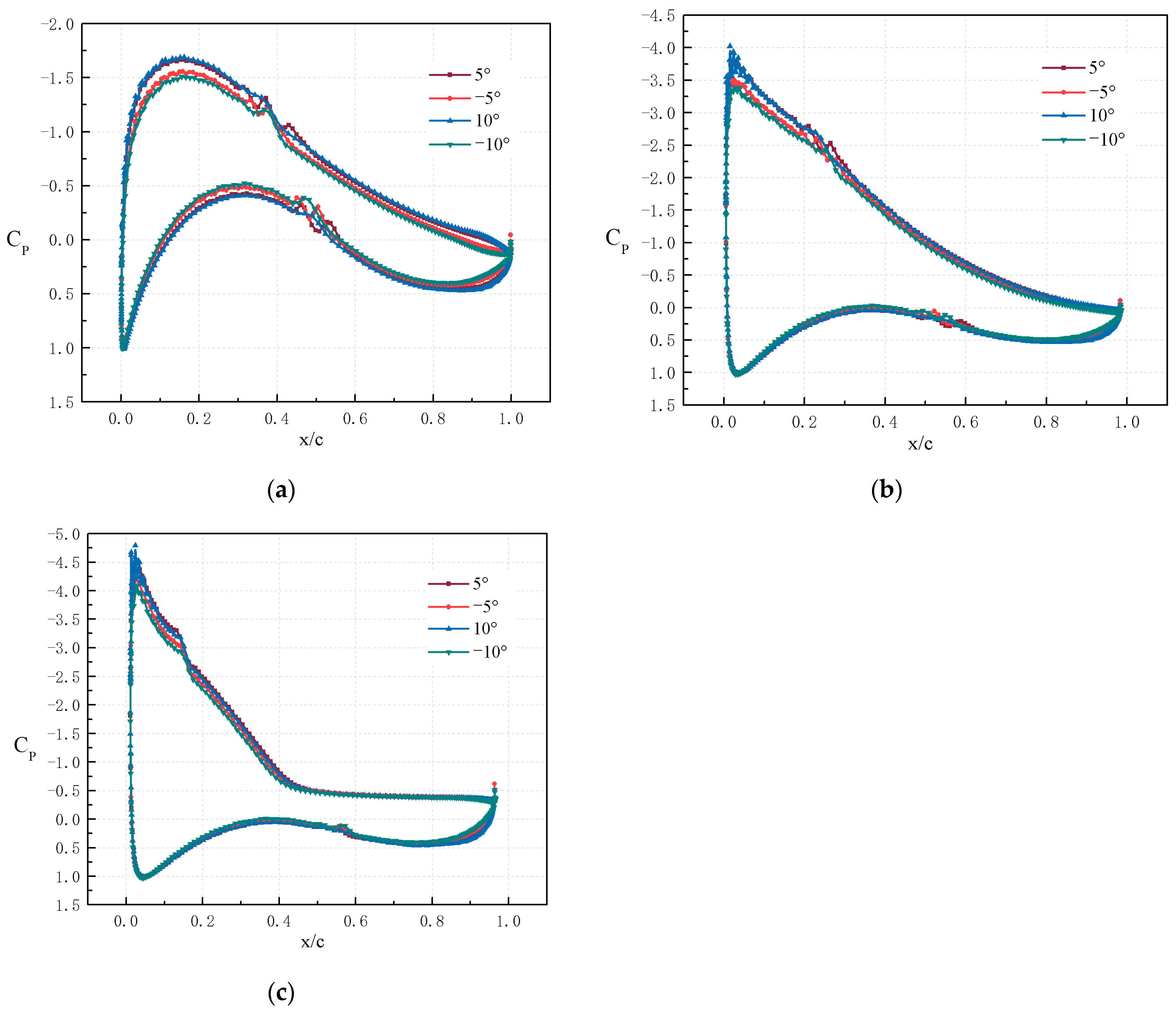
The lift coefficient initially increases and then decreases as the angle of attack increases. When the angle of attack exceeds the critical angle of attack, the airfoil is in a stall condition. The results show that, when the flap is deflected upward, the stall is slightly delayed, while when it is deflected downward, the stall occurs earlier. The reason for the change in the lift and drag performance is the change in airfoil curvature caused by flap deflection, which leads to a variation in the effective angle of attack. Figure 8 shows the influence of flap deflection angle on pressure distribution. Three flow conditions are mainly considered: laminar flow, pre-stall, and deep stall conditions. The results indicate that the flap changes the pressure distribution of the entire airfoil, not only the flap part, especially under attached flow conditions. The suction peak increases for positive deflection and decreases for negative deflection. This effect gradually weakens as the angle of attack increases. Conversely, once the airfoil stalls, the change in pressure distribution can only be observed in a limited area around the suction peak and the flap section. The oscillation of pressure coefficient is caused by the transition of the boundary layer from laminar to turbulent, resulting in the generation of separation bubbles.

5.2. Influence of Flap Length

The lift and drag coefficient of the airfoil with flap lengths of 0.2 c and 0.3 c are shown in Figure 9 and Figure 10, which is similar to the 0.1 c case. However, the influence is amplified with increasing flap length, particularly in the linear region. With increasing flap length, the influence on the drag coefficient is also amplified, but the changes are mainly concentrated under deep stall conditions. In addition, the increase in flap length makes the impact of flap deflection angle changes on the critical angle of attack more pronounced. For upward deflection, the critical angle of attack is delayed as the flap length increases, while downward deflection causes earlier stall onset.
As shown in Figure 11 and Figure 12, the influence of flap deflection angle on lift and drag coefficients is more significant within the small to medium angle of attack range. At large angles of attack, while the influence of flap deflection angle on increasing the lift coefficient weakens, it remains effective in delaying airflow separation and improving stall characteristics.
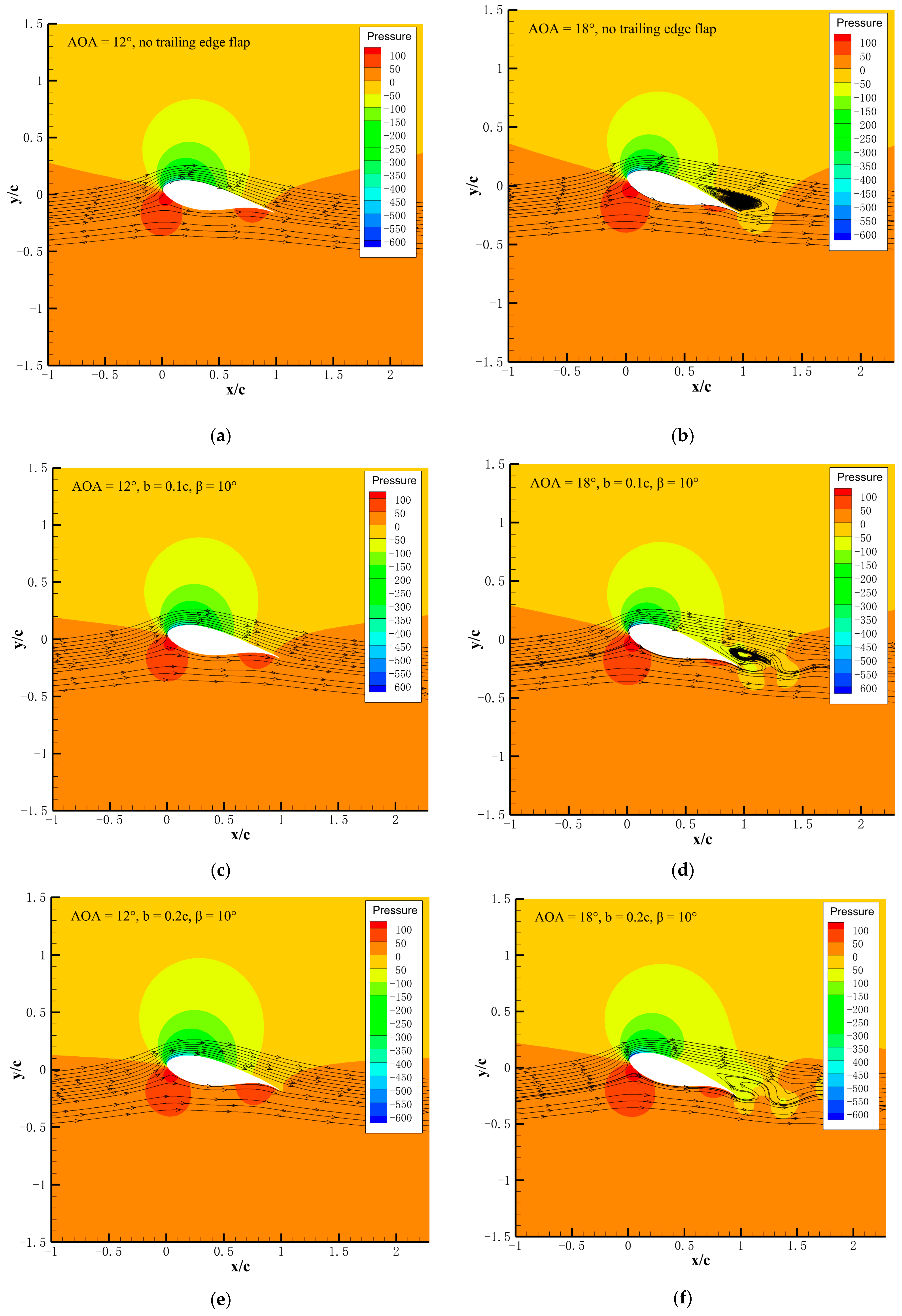
Figure 13 presents the flow deviation caused by the increase in flap size and provides streamlines and pressure contours. It mainly focuses on comparing the flow structures between the attached flow at an angle of attack of 12° and the separated flow at 18°. The increase in trailing edge flap size leads to an expansion of the low-pressure region on the upper surface and an increase in the high-pressure region on the lower surface. Meanwhile, the increase in airfoil curvature also results in an increase in the separation area of the trailing edge.
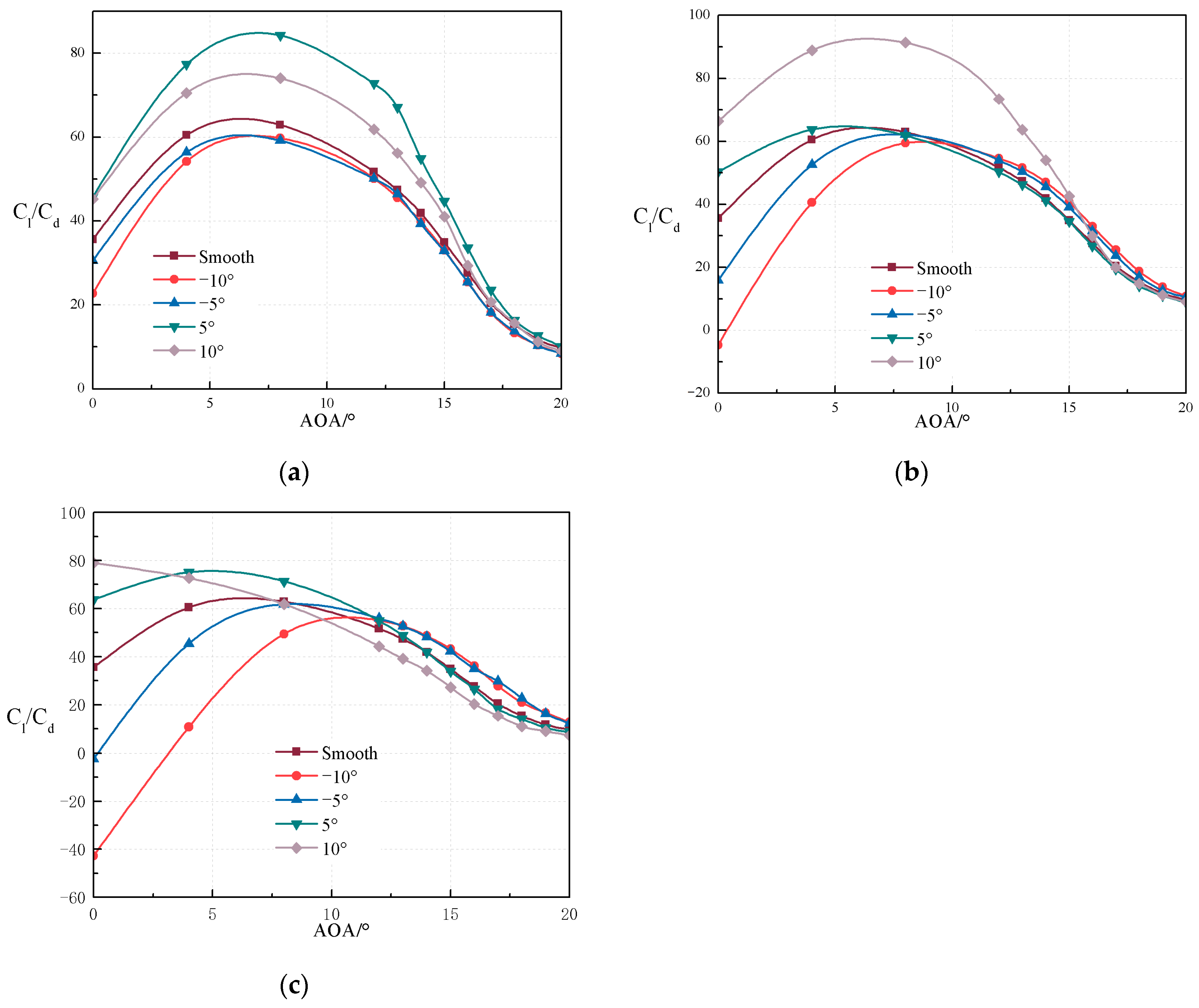
The deflection of trailing edge flaps generates aerodynamic forces to produce either additional or reduced lift as required, effectively achieving load control objectives. Moreover, the optimization of geometric configurations is conventionally guided by dual performance metrics: the low drag and the high lift-to-drag ratio. In Figure 14, compared to the airfoil without trailing edge flaps configuration, the lift-to-drag ratio for different flap lengths and deflection angles shows that positive flap deflection and increasing flap length can effectively improve the lift-to-drag ratio at small angles of attack. Conversely, as the angle of attack increases, the lift-to-drag ratio decreases slightly. Among the three length scales studied, the 0.1 c flap exhibits superior performance enhancement, achieving elevated lift-to-drag ratios for nearly all positive deflection settings. Due to the scale of load variation in airfoil motion, the optimal choice of flap length is determined. Based on the load variation during stall in the steady condition, the 0.1 c chord length flap is used as the basic model. At this time, the airfoil has a higher lift-to-drag ratio and a smaller impact on the critical stall angle.

5.3. Comprehensive Optimal Parameters

The above study shows that, under different flaps length, trailing edge flaps with a 10° deflection angle generally have the best performance. In this case, when the flap length is 0.1, the trailing edge flap has a good lifting effect at all angles of attack without producing any side effects. After comprehensively considering the influence of flap length and deflection angle on aerodynamic performance, this paper concludes that the optimal flap length is 0.1 c and the optimal deflection angle is 10°. Under these parameters, the aerodynamic efficiency of the wind turbine reaches a high level.

6. Conclusions

The aerodynamic characteristics of the FFA-W3-241 static airfoil are calculated using CFD methods in this paper. The influence of trailing edge flaps on the aerodynamic characteristics is studied, and the quantitative variation laws of lift and drag coefficients with different flap lengths and deflection angles are revealed. The principal findings derived from this study are summarized below:
1. The effect of trailing edge flaps on the aerodynamic characteristics of FFA-W3-241 airfoil is investigated. The flap lengths and deflection angles have a significant regulatory effect on the lift and drag coefficients of the airfoil.
2. The influence of different combinations of flap configurations on performance is comprehensively analyzed. As the flap length increases, the lift coefficient of the airfoil shows an upward trend within a certain range, but when the flap length exceeds a certain critical value, the influence of improving the lift coefficient gradually weakens. As the angle of attack increases, the flap deflection angle has a more significant effect on improving the lift coefficient. However, when approaching the stall angle of attack, the regulating effect of the flap deflection angle on aerodynamic performance gradually weakens. Furthermore, negative deflection angles can delay airflow separation and improve the stall characteristics of the airfoil under specific operating conditions.
3. It is found that there exists an optimal combination of flap length and deflection angle by comparing the aerodynamic performance under different combinations, which can significantly improve the lift-to-drag ratio under specific operating conditions. In the range of medium angles of attack, the aerodynamic performance of the airfoil is optimal when the flap length is 0.1 c and the flap deflection angle is 10°.
This study provides quantitative analysis methods and data support for the aerodynamic performance optimization of wind turbine airfoils, especially in the trailing edge flap parameter optimization. However, there are some limitations in this paper. This paper mainly focuses on the static trailing edge flaps and future research can further explore the dynamic characteristics of the flaps. The trailing edge flaps also have some impact on the aeroelasticity of wind turbines, which can be discussed in the future. Meanwhile, trailing edge flaps can be combined with other aerodynamic control methods, such as airfoil slits and leading-edge devices, to achieve more efficient aerodynamic performance control.

Author Contributions

Conceptualization, Y.Q. and Z.W.; methodology, J.X., Z.J., Y.Z. and G.Y.; software, J.X., Z.J. and Y.Q.; validation, Y.Z., G.Y. and Z.W.; formal analysis, J.X.; investigation, Z.J., Y.Z. and G.Y.; resources, Y.Q.; data curation, J.X., Y.Q. and Z.W.; writing—original draft preparation, J.X., Y.Q. and Z.W.; writing—review and editing, J.X., Y.Q. and Z.W.; funding acquisition, J.X., Y.Q. and Z.W. All authors have read and agreed to the published version of the manuscript.

Funding

This work was supported by the National Natural Science Foundation of China (Grant No. 52006098) and the College Student Innovation Training Program Project of Jiangsu Province (Grant No. 202411276080Y).

Institutional Review Board Statement

Not applicable.

Informed Consent Statement

Not applicable.

Data Availability Statement

All data have been shown in the paper.

Conflicts of Interest

The authors declare no conflicts of interest.

References

  1. Bošnjaković, M.; Katinić, M.; Santa, R.; Marić, D. Wind turbine technology trends. Appl. Sci. 2022, 12, 8653. [Google Scholar] [CrossRef]
  2. Mansi, A.; Aydin, D. The impact of trailing edge flap on the aerodynamic performance of small-scale horizontal axis wind turbine. Energy Convers. Manag. 2022, 256, 115396. [Google Scholar] [CrossRef]
  3. Sun, Y.; Qian, Y.; Gao, Y.; Wang, T.; Wang, L. Stall control on the wind turbine airfoil via the single and dual-channel of combining bowing and suction technique. Energy 2024, 290, 130224. [Google Scholar] [CrossRef]
  4. Qian, Y.; Zhang, Y.; Sun, Y.; Wang, T. Numerical investigations of the flow control effect on a thick wind turbine airfoil using deformable trailing edge flaps. Energy 2023, 265, 126327. [Google Scholar] [CrossRef]
  5. Zhu, H.; Hao, W.; Li, C.; Luo, S.; Liu, Q.; Gao, C. Effect of geometric parameters of Gurney flap on performance enhancement of straight-bladed vertical axis wind turbine. Renew. Energy 2021, 165, 464–480. [Google Scholar] [CrossRef]
  6. Wilson, D.; Barlas, T.; Berg, D.; van Kuik, G.; Resor, B. Active aerodynamic blade distributed flap control design procedure for load reduction on the UPWIND 5MW wind turbine. In Proceedings of the 48th AIAA Aerospace Sciences Meeting Including the New Horizons Forum and Aerospace Exposition, Orlando, FL, USA, 4–7 January 2010; p. AIAA-2010-254. [Google Scholar]
  7. Timmer, W.A.; Van Rooij, R.P.J.O.M. Summary of the Delft University wind turbine dedicated airfoils. J. Sol. Energy Eng. 2003, 125, 488–496. [Google Scholar] [CrossRef]
  8. McWilliam, M.K.; Barlas, T.K.; Madsen, H.A.; Zahle, F. Aero-elastic wind turbine design with active flaps for AEP maximization. Wind. Energy Sci. 2018, 3, 231–241. [Google Scholar] [CrossRef]
  9. Hao, W.; Mao, H.; Lyu, S.; Li, C. Study on aerodynamic load reduction and efficiency improvement of VAWT based on DTEF. Ocean. Eng. 2022, 260, 111966. [Google Scholar] [CrossRef]
  10. Daynes, S.; Weaver, P.M. Design and testing of a deformable wind turbine blade control surface. Smart Mater. Struct. 2012, 21, 105019. [Google Scholar] [CrossRef]
  11. Bak, C.; Gaunaa, M.; Andersen, P.B.; Buhl, T.; Hansen, P.; Clemmensen, K. Wind tunnel test on airfoil Risø-B1-18 with an Active Trailing Edge Flap. Wind. Energy 2010, 13, 207–219. [Google Scholar] [CrossRef]
  12. Troldborg, N. Computational study of the risø-b1-18 airfoil with a hinged flap providing variable trailing edge geometry. Wind. Eng. 2005, 29, 89–113. [Google Scholar] [CrossRef]
  13. Wolff, T.; Ernst, B.; Seume, J.R. Aerodynamic behavior of an airfoil with morphing trailing edge for wind turbine applications. J. Phys. Conf. Ser. 2014, 524, 012018. [Google Scholar] [CrossRef]
  14. Gerontakos, P.; Lee, T. Piv study of flow around unsteady airfoil with dynamic trailing-edge flap deflection. Exp. Fluids 2008, 45, 955. [Google Scholar] [CrossRef]
  15. Troolin, D.R.; Longmire, E.K.; Lai, W.T. Time resolved PIV analysis of flow over a NACA 0015 airfoil with Gurney flap. Exp. Fluids 2006, 41, 241–254. [Google Scholar] [CrossRef]
  16. Hao, L.S.; Gao, Y.W. Effect of gurney flap geometry on a S809 airfoil. Int. J. Aerosp. Eng. 2019, 2019, 9875968. [Google Scholar] [CrossRef]
  17. Özden, M.; Genç, M.S.; Koca, K. Investigation of the effect of hidden vortex generator-flap integrated mechanism revealed in low velocities on wind turbine blade flow. Energy Convers. Manag. 2023, 287, 117107. [Google Scholar] [CrossRef]
  18. LI, C.; XU, Y.; XU, J. Influence of slot on wind turbine airfoil with trailing-edge flaps. J. Eng. Thermophys. 2011, 32, 1851–1854. [Google Scholar]
  19. Hao, W.; Bashir, M.; Li, C.; Sun, C. Flow control for high-solidity vertical axis wind turbine based on adaptive flap. Energy Convers. Manag. 2021, 249, 114845. [Google Scholar] [CrossRef]
  20. Hao, W.; Li, C.; Ye, Z.; Zhu, H.; Ding, Q. Numerical investigation of the load reduction potential of trailing edge flap based on closed-loop control. J. Renew. Sustain. Energy 2018, 10, 053301. [Google Scholar] [CrossRef]
  21. Seyednia, M.; Vakilipour, S.; Masdari, M. Numerical investigation of dynamic stall over a wind turbine pitching airfoil by using openfoam. Int. J. Mech. Aerosp. Ind. Mechatron. Manuf. Eng. 2017, 11, 1466–1477. [Google Scholar]
  22. Seyednia, M.; Masdari, M.; Vakilipour, S. The influence of oscillating trailing-edge flap on the dynamic stall control of a pitching wind turbine airfoil. J. Braz. Soc. Mech. Sci. Eng. 2019, 41, 192. [Google Scholar] [CrossRef]
  23. Zhu, W.; Behrens, T.; Shen, W. Hybrid immersed boundary method for airfoils with a trailing-edge flap. AIAA J. 2013, 51, 30–41. [Google Scholar] [CrossRef]
  24. Liu, Q.; Miao, W.; Li, C.; Hao, W.; Zhu, H.; Deng, Y. Effects of trailing-edge movable flap on aerodynamic performance and noise characteristics of VAWT. Energy 2019, 189, 116271. [Google Scholar] [CrossRef]
  25. Arredondo-Galeana, A.; Young, A.M.; Smyth, A.S.; Viola, I.M. Unsteady load mitigation through a passive trailing-edge flap. J. Fluids Struct. 2021, 106, 103352. [Google Scholar] [CrossRef]
  26. Mancini, P.; Medina, A.; Jones, A.R. Experimental and analytical investigation into lift prediction on large trailing edge flaps. Phys. Fluids 2019, 31, 013106. [Google Scholar] [CrossRef]
  27. Zhuang, C.; Yang, G.; Zhu, Y.; Hu, D. Effect of morphed trailing-edge flap on aerodynamic load control for a wind turbine blade section. Renew. Energy 2020, 148, 964–974. [Google Scholar] [CrossRef]
  28. He, G.; Deparday, J.; Siegel, L.; Henning, A.; Mulleners, K. Stall delay and leading-edge suction for a pitching airfoil with trailing-edge flap. AIAA J. 2020, 58, 5146–5155. [Google Scholar] [CrossRef]
  29. Tian, H.; Shan, X.; Wang, H.; Li, X.; Su, Y.; Wang, J. Enhanced piezoelectric energy harvesting performance using trailing-edge flap. Ocean. Eng. 2023, 285, 115443. [Google Scholar] [CrossRef]
  30. Rivero, A.E.; Fournier, S.; Manolesos, M.; Cooper, J.E.; Woods, B.K. Experimental aerodynamic comparison of active camber morphing and trailing-edge flaps. AIAA J. 2021, 59, 2627–2640. [Google Scholar] [CrossRef]
  31. Watkins, J.; Bouferrouk, A. The effects of a morphed trailing-edge flap on the aeroacoustic and aerodynamic performance of a 30P30N aerofoil. Acoustics 2022, 4, 248–267. [Google Scholar] [CrossRef]
  32. Haldar, A.; Jansen, E.; Hofmeister, B.; Bruns, M.; Rolfes, R. Analysis of novel morphing trailing edge flap actuated by multistable laminates. AIAA J. 2020, 58, 3149–3158. [Google Scholar] [CrossRef]
  33. Ameduri, S.; Galasso, B.; Noviello, M.C.; Dimino, I.; Concilio, A.; Catalano, P.; Shreedharan, S. Design and optimization of a compliant morphing trailing edge for high-lift generation. Appl. Sci. 2025, 15, 2529. [Google Scholar] [CrossRef]
  34. Chen, Z.J.; Stol, K.A.; Mace, B.R. Wind turbine blade optimisation with individual pitch and trailing edge flap control. Renew. Energy 2017, 103, 750–765. [Google Scholar] [CrossRef]
  35. Li, X.; Yang, K.; Wang, X. Experimental and numerical analysis of the effect of vortex generator height on vortex characteristics and airfoil aerodynamic performance. Energies 2019, 12, 959. [Google Scholar] [CrossRef]
  36. Yue, H.; Zhang, H.; Zhu, Q.; Ai, Y.; Tang, H.; Zhou, L. Wake dynamics of a wind turbine under real-time varying inflow turbulence: A coherence mode perspective. Energy Convers. Manag. 2025, 332, 119729. [Google Scholar] [CrossRef]
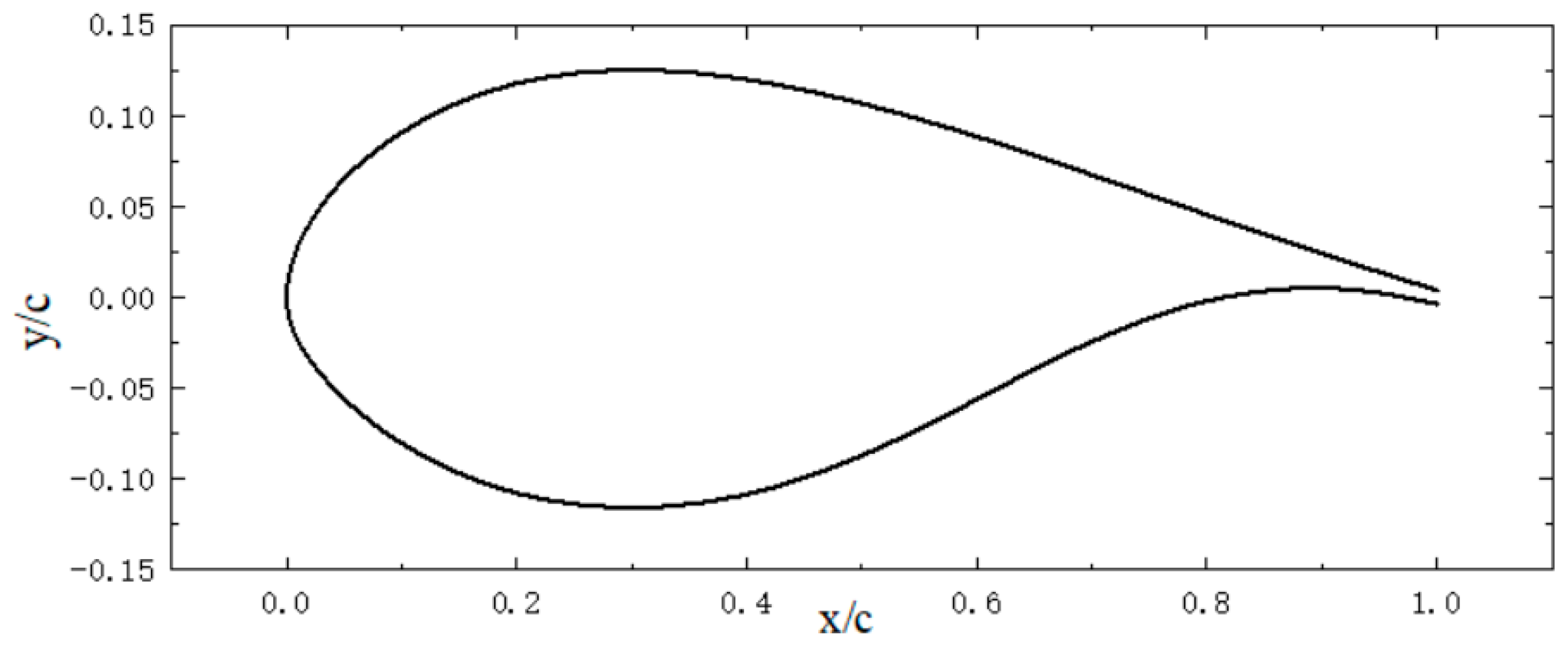
Figure 1. FFA-W3-241 basic airfoil.
Machines 13 00366 g001
Figure 2. Deformation of trailing edge flaps.
Machines 13 00366 g002
Figure 3. Calculation grid of airfoil with 10° flap deflection angle: (a) Airfoil. (b) Trailing edge. The numerical simulation of the airfoil flow field is solved using the CFD solver ANSYS Fluent (ANSYS Fluent Version 2022 R1). The solver adopts implicit solving based on pressure velocity coupling algorithm, and the Reynolds-Averaged Navier–Stokes (RANS) method is used. During normal operation of a wind turbine blade, air can be considered as an incompressible fluid due to the low Mach number of the outflow. Flow separation and dynamic stall phenomena occur on the airfoil surface, accompanied by the formation and shedding of dynamic stall vortices. Therefore, the coupled algorithm is used. To ensure calculation accuracy, all parameters used in numerical calculation employ a second-order upwind scheme. When the airflow does not separate, a steady solver is used, and when the airflow separates, a unsteady solver is used. To meet the convergence criteria, the maximum calculated residuals in the flow field are reduced to 10−7.
Machines 13 00366 g003
Figure 4. Grid independence calculation results: (a) Lift coefficient ( C l ). (b) Drag coefficient ( C d ).
Machines 13 00366 g004
Figure 5. Comparison of numerical simulation and experimental results: (a) C l ; (b) C d .
Machines 13 00366 g005
Figure 6. The lift and drag coefficient of the airfoil with a flap length of 0.1 c under different flap deflection angles: (a) C l ; (b) C d .
Machines 13 00366 g006
Figure 7. The lift and drag coefficient of the airfoil with a flap length of 0.1 c under different angles of attacks: (a) C l ; (b) C d .
Machines 13 00366 g007
Figure 8. The influence of flap deflection angle on the surface pressure with a flap length of 0.1 c : (a) α = 4°; (b) α = 12°; (c) α = 18°.
Machines 13 00366 g008
Figure 9. The lift and drag coefficient of the airfoil with a flap length of 0.2 c under different flap deflection angles: (a) C l ; (b) C d .
Machines 13 00366 g009
Figure 10. The lift and drag coefficient of the airfoil with a flap length of 0.3 c under different flap deflection angles: (a) C l ; (b) C d .
Machines 13 00366 g010
Figure 11. The lift and drag coefficient of the airfoil with a flap length of 0.2 c under different angles of attacks: (a) C l ; (b) C d .
Machines 13 00366 g011
Figure 12. The lift and drag coefficient of the airfoil with a flap length of 0.3 c under different angles of attacks: (a) C l ; (b) C d .
Machines 13 00366 g012
Figure 13. Pressure distribution near the airfoil under different flap lengths and flap deflection angles: (a) α = 12°, no trailing edge flap; (b) α = 18°, no trailing edge flap; (c) α = 12°, b = 0.1 c , β = 10°; (d) α = 18°, b = 0.1 c , β = 10°; (e) α = 12°, b = 0.2 c , β = 10°; (f) α = 18°, b = 0.2 c , β = 10°; (g) α = 12°, b = 0.3 c , β = 10°; (h) α = 18°, b = 0.3 c , β = 10°.
Machines 13 00366 g013aMachines 13 00366 g013b
Figure 14. The lift and drag characteristics under different flap lengths: (a) b = 0.1 c ; (b) Flap b = 0.2 c ; (c) b = 0.3 c .
Machines 13 00366 g014
Table 1. Basic parameters of calculation conditions.
ParameterValue
Average inflow velocity V 14.8 m/s
Reynolds number Re 106
Turbulence intensity TI 1%
Attack of angle α 0–20°
Flap length b 0.1 c , 0.2 c , 0.3 c
Flap deflection angle β ±5°, ±10°
Table 2. Grid independence calculation results.
SchemeGrid NumberAOA = 4°AOA = 12°AOA = 16°
C l C d C l C d C l C d
coarse grid319920.71250.01311.57930.03181.69370.0619
medium grid524160.69860.01281.55020.03091.61700.0634
fine grid1318380.69670.01221.56280.02891.60840.0610
Disclaimer/Publisher’s Note: The statements, opinions and data contained in all publications are solely those of the individual author(s) and contributor(s) and not of MDPI and/or the editor(s). MDPI and/or the editor(s) disclaim responsibility for any injury to people or property resulting from any ideas, methods, instructions or products referred to in the content.