Article

Dynamic Analysis and Resonance Control of a Tunable Pendulum Energy Harvester Using Cone-Based Continuously Variable Transmission

1
Graduate School of Science and Technology, Gunma University, Gunma 376-8515, Japan
2
Department of Mechanical Engineering, Naresuan University, 99 Moo 9, Thapo Sub-District, Muang District, Phitsanulok 65000, Thailand
3
Department of Electrical and Electronic 1, Posts and Telecommunications Institute of Technology, Hanoi 100000, Vietnam
4
Division of Mechanical Science and Technology, Gunma University, Gunma 376-8515, Japan
*
Authors to whom correspondence should be addressed.
Machines 2025, 13(5), 365; https://doi.org/10.3390/machines13050365
Submission received: 31 March 2025 / Revised: 25 April 2025 / Accepted: 27 April 2025 / Published: 29 April 2025
(This article belongs to the Section Electromechanical Energy Conversion Systems)

Abstract

This paper investigates the design and performance of a tunable pendulum energy harvester (TPEH) integrated with cone continuously variable transmission (CVT) to enhance energy harvesting efficiency in broadband and non-stationary vibrational environments. The cone CVT mechanism enables the tunability of the harvester’s natural frequency, allowing it to dynamically adapt and maintain resonance across varying excitation frequencies. A specific focus is placed on the system’s behavior under chirp signal base excitation, which simulates a time-varying frequency environment. Experimental and analytical approaches are employed to evaluate the system’s dynamic response, energy output, and frequency adaptation capabilities. The results demonstrate that the proposed TPEH system achieves significant energy harvesting performance improvements by leveraging the cone CVT to optimize power generation under resonance conditions. The system is also shown to be effective in maintaining stable operation over a wide range of frequencies, demonstrating its versatility for real-world vibrational energy harvesting applications. This research highlights the importance of tunability in energy harvesting systems and the role of mechanical transmission mechanisms in improving adaptability. The proposed design has strong potential for applications in environments with non-stationary vibrations, such as transportation systems, industrial machinery, and infrastructure monitoring.

1. Introduction

Energy harvesting is the process of capturing and converting small amounts of energy from ambient sources into usable electrical power. This method, often referred to as “environmental power generation”, enables sustainable energy utilization without relying on conventional power sources. The principle behind energy harvesting is to extract energy from naturally occurring phenomena, such as solar radiation, thermal gradients, and mechanical vibrations, which are abundant and renewable. Among these, mechanical energy harvesting has gained significant interest due to its ability to harness vibrations, movements, and deformations from various environments. These sources provide a continuous supply of energy that can be used to power low-energy electronic devices, reducing the dependence on batteries and wired power sources.
Various renewable energy sources have been explored for harvesting applications, including solar energy [1], thermal energy [2], and mechanical energy [3]. Among them, mechanical energy harvesting has been particularly useful in scenarios where other energy sources are unavailable or impractical. One of the prominent approaches in mechanical energy harvesting is the use of pendulum-based systems. For example, [4] focuses on the mechanics of pendulum-based systems for energy harvesting, specifically aiming to convert the kinetic energy from pendulum motion into usable electrical power. These systems have been widely adopted in environments characterized by ultralow-frequency oscillations, such as ocean waves, human motion, and structural vibrations [5]. The advantage of these systems lies in their ability to operate under low-frequency excitation while maintaining efficient energy conversion. Using the principles of dynamic motion and resonance, pendulum-based harvesters [6,7,8,9,10,11,12] can significantly improve energy capture efficiency, making them suitable for a wide range of applications, including wearable electronics, structural health monitoring, and marine energy harvesting. The proposed method targets enhanced energy harvesting under non-stationary excitation conditions, with applications ranging from industrial machinery to transportation systems and infrastructure monitoring.
In parallel, other vibration-related research has explored energy dissipation and control rather than energy harvesting. For instance, a study titled “Frequency-dependent equivalent impedance analysis for optimizing vehicle inertial suspensions” [13] investigates how modifying a vehicle’s suspension impedance over frequency can improve ride comfort and dynamic stability. While both approaches rely on analyzing frequency-dependent dynamics, their goals diverge—our system seeks to extract electrical energy, whereas the inertial suspension study focuses on vibration reduction.
Further research conducted by [14] Punyakaew introduced an adaptive tuned vibration absorber (ATVA) as a solution to mitigate excessive vibrations in primary structures. The ATVA was designed to counteract these effects by dynamically adjusting its parameters in response to changing excitation frequencies. A novel implementation of this concept involved the integration of cone-based continuously variable transmission (CVT) to enhance a dynamic vibration absorber (DVA). The integration of cone CVT enabled the real-time tuning of the absorber, enhancing adaptability to varying conditions and improving vibration mitigation efficiency compared to that of conventional passive systems.
In parallel, research in the field of vibrations has also focused on energy dissipation and control. For example, a study by Shi et al. [15] explored how frequency-tuned impedance modification in vehicle suspensions can improve ride comfort and dynamic stability.
Another relevant study [16] proposed a passive tuning strategy. Their system uses a parametric rolling pendulum that self-adjusts via geometric reconfiguration, without the need for real-time sensing or control. While mechanically simpler, this passive design may offer limited adaptability under broadband excitation compared to active systems.
In contrast, the system proposed in this paper actively modulates the pendulum’s natural frequency through continuous feedback and real-time actuation. Using PID-controlled cone CVT, it provides rapid adaptation to changing vibration frequencies, offering improved performance under a wider range of operating conditions. This highlights a key distinction between passive and active strategies while also suggesting a potential direction for hybrid systems that combine mechanical simplicity with control flexibility.
A broader context is provided in a comprehensive review by Chen et al. [5]. The review emphasizes the importance of tunability in maximizing performance at varying excitation frequencies. Our work builds upon this foundation by proposing a novel control-centric architecture that integrates active feedback with mechanical adaptability, setting it apart from traditional passive and semi-passive approaches.
Although the primary focus of this paper is energy harvesting systems, it is also worth considering the potential of such systems to contribute to vibration suppression. Several studies have shown that tunable energy harvesters may exhibit damping effects similar to those of tuned mass dampers (TMDs). Several studies have addressed this issue [17,18,19,20,21] For example, [5] provides a foundation for viewing energy harvesting systems not only as power sources but also as integral components in vibration control.
These studies of energy harvesting and vibration control demonstrate the potential for the development of highly efficient and adaptive systems capable of operating under fluctuating environmental conditions. The combination of mechanical energy harvesting and active vibration control strategies opens new possibilities for applications in renewable energy, industrial machinery, and structural engineering. Future research in this area may focus on optimizing the energy conversion process, enhancing material efficiency, and integrating advanced control algorithms to improve the performance of these systems further.
In this paper, we focus on creating an ideal system that can be tunable to a wide range of excitation frequencies, and we accomplish this tuning operation with low energy consumption by using cone continuous transmission (CVT), testing performance using chirp signal base excitation, and investigating the system via resonance control and non-resonance control [22].
The objective of the proposed energy harvester is to develop a self-adaptive, pendulum-based vibration energy harvesting system [23,24,25,26,27,28] that can operate efficiently in non-stationary, broadband, and low-frequency vibration environments. These conditions are commonly found in vehicular systems (automobiles and trains), industrial machinery, and structural components such as bridges or buildings. In such applications, ambient vibrations often fluctuate due to varying loads, speed changes, or environmental disturbances. The harvester is designed to autonomously adjust its natural frequency in real time using cone-type continuously variable transmission (CVT) coupled with a pendulum, enabling continuous resonance tuning and improved energy extraction. This adaptability is critical for maximizing power generation from dynamic sources without manual retuning or external energy input for control.
The main contributions of this paper are summarized as follows:
This paper presents a novel active tuning mechanism for pendulum-based energy harvesters, utilizing cone-based continuously variable transmission (CVT) in conjunction with a PID controller for real-time resonance tracking. Through a numerical simulation, the proposed method demonstrates the following advantages over traditional passive or nonlinear systems:
  • Adaptive resonance tuning in response to time-varying vibration frequencies;
  • Enhanced energy harvesting efficiency across a broad and dynamic frequency range;
  • Precise control enabled by feedback-driven PID regulation;
  • Greater flexibility and robustness for real-world applications with unpredictable vibrational environments.
The numerical results indicate that the proposed approach offers a significant improvement over existing passive or nonlinear tuning strategies by effectively bridging the gap between tunability, responsiveness, and control precision in vibration-based energy harvesting.
This paper extends our previous work, “Tunable Pendulum Energy Harvester Using Cone Continuously Variable Transmission”, presented at the 2024 21st International Conference on Electrical Engineering/Electronics, Computer, Telecommunications and Information Technology (ECTI-CON) [29], where the preliminary concept of a pendulum-based energy harvester using cone CVT was introduced. In this extended version, we incorporate a PID controller for active tuning, present comprehensive numerical simulations, and perform comparative analyses to demonstrate the improved energy harvesting performance.
This paper is organized as follows: In Section 2, we present the related work and a brief review of the research related to energy harvesting systems. In Section 3, we detail the materials and methods. The key component of the system is cone continuously variable transmission (CVT), which adjusts the gear ratio by varying the contact position between the driving and driven wheels along the conical surface. The gear ratio is dependent on the relative positions of the wheels, with the position being determined by the cone’s geometry. The system analysis is divided into two main parts: the first focuses on developing a mathematical model to describe the system’s dynamics, and the second involves experimental performance testing using a chirp signal as the base excitation. This testing enables an evaluation of the system’s frequency response across a range of frequencies, providing valuable insights into its dynamic behavior, resonance characteristics, and practical performance. In Section 4, the equation of the system is derived starting from the energy of the system, circuits, motion of the energy harvester, natural frequency, and region for chirp signal base excitation. In Section 5, we show numerical examples to illustrate the effectiveness of the proposed method and analyze how the system responds to chirp signal base excitation, which represents real-world dynamic conditions. Finally, in Section 6, we draw conclusions on the proposed method based on both the system analysis and chirp signal base excitation.

2. Related Papers

Pendulum-based energy harvesters are widely studied because they efficiently capture energy from low-frequency vibrations. Sarker et al. [30] classify these systems into three types: linear, rotational, and parametric systems. They stress the importance of tunability to maintain resonance under varying conditions, which helps optimize energy capture. Yang et al. [31] discuss nonlinear vibration energy harvesting. They show how nonlinear systems can expand bandwidth and enable both energy harvesting and vibration control. This supports the idea of multifunctional energy harvesters, which is also a goal in this study. Punyakaew et al. [9] propose a passive auto-tuning pendulum system that adjusts its frequency using parametric resonance. While this works for certain frequency ranges, it lacks adaptability to quickly changing or broad-frequency excitations, limiting its real-world applications. Dotti et al. [32] explore the behavior of parametric pendulums under reciprocating excitation to identify stable conditions for energy harvesting. Although effective, their method relies on passive dynamics, which do not adapt to shifting environmental conditions. Beeby et al. [3] discuss the challenges of vibration energy harvesting in microsystems, stressing the need for adaptable mechanisms that can work in real-world dynamic environments. However, existing systems often struggle with handling a wide range of changing vibrations.
In contrast to these works, this research introduces a new active tuning mechanism using cone-based continuously variable transmission (CVT) and a PID controller. This system allows the energy harvester to track resonance in real time, ensuring that it can adapt quickly to changing vibrations. Unlike passive systems, this method offers better adaptability and more precise control over the system. As a result, the system is more efficient and flexible, making it ideal for environments where the frequency of vibrations is unpredictable or constantly changing.
From the Table 1 the proposed method introduces a significant advancement in pendulum-based energy harvesting systems by utilizing cone-based continuously variable transmission (CVT) combined with a PID controller for active, real-time resonance tracking. This approach addresses several limitations found in traditional energy harvesting systems, such as passive tuning and limited frequency adaptability.
Overall, this combination of adaptive tuning, precise control, and a wide frequency bandwidth makes the proposed method a more efficient, reliable, and versatile solution for energy harvesting in dynamic, real-world environments, outperforming conventional passive and nonlinear systems.

3. Material and Methods

3.1. Working Principle of Cone CVT

The gear CVT cone type combines the principles of variable-radius cones with geared transmission, enabling smooth and continuous variations in the gear ratio without traditional stepped gears. Its working principle is as follows:
A conical gear (or a pair of meshing cone-shaped gears) is used, where the gear teeth are distributed along the tapering surface. By sliding the driven gear or roller along the axis of the cone, the system changes the point of contact, which effectively alters the gear radius and thus the transmission ratio.
This allows for continuous and smooth shifting between gear ratios without interrupting power flow. In active systems, actuators or control algorithms (e.g., PID controllers) automatically adjust the gear engagement position to match the dynamic load or speed requirements in real time. Figure 1 depicts isometric and schematic representations of cone-based continuously variable transmission (CVT). The system comprises two friction-coated conical components with an intermediary wheel that moves along a sliding mechanism. This movement enables power transfer between the input and output cones. By adjusting the wheel’s contact position along the cone surfaces, the transmission ratio is modified through changes in the effective radii. A servo DC motor, integrated with a ball screw, precisely governs the wheel’s position, ensuring accurate gear ratio adjustments.
It is assumed that there is no slip between the cones and the wheel; hence, the gear ratio G between the input and output cones can be defined as shown below.
The governing equation, as shown in our previous work, “Tunable Pendulum Energy Harvester Using Cone Continuously Variable Transmission” [6], with further improvements in parameter analysis, is written as
G = θ o θ i = D l ( D d ) z cos α d l + ( D d ) ( z cos α + d w sin α )
It is noticed that the gear ratio of the cone CVT (G) depends on the wheel position (z). Therefore, from (1), the relationship between the wheel position (z) and the gear ratio of the cone CVT (G) can be expressed as
z = D l d l G d w sin α G ( D d ) ( G + 1 ) ( D d ) cos α
where G is the gear ratio, θ o is the angular displacement of the output cone, θ i is the angular displacement of the input cone, D is the larger diameter of the cone, d is the smaller diameter of the cone, z is the position of the wheel, d w is the diameter of the wheel, l is the length of the cone, and α is the taper angle.

3.2. Methodology

The methodology of this study involves two experimental approaches: the first involves harmonic excitation, while the second utilizes chirp signal-based excitation.
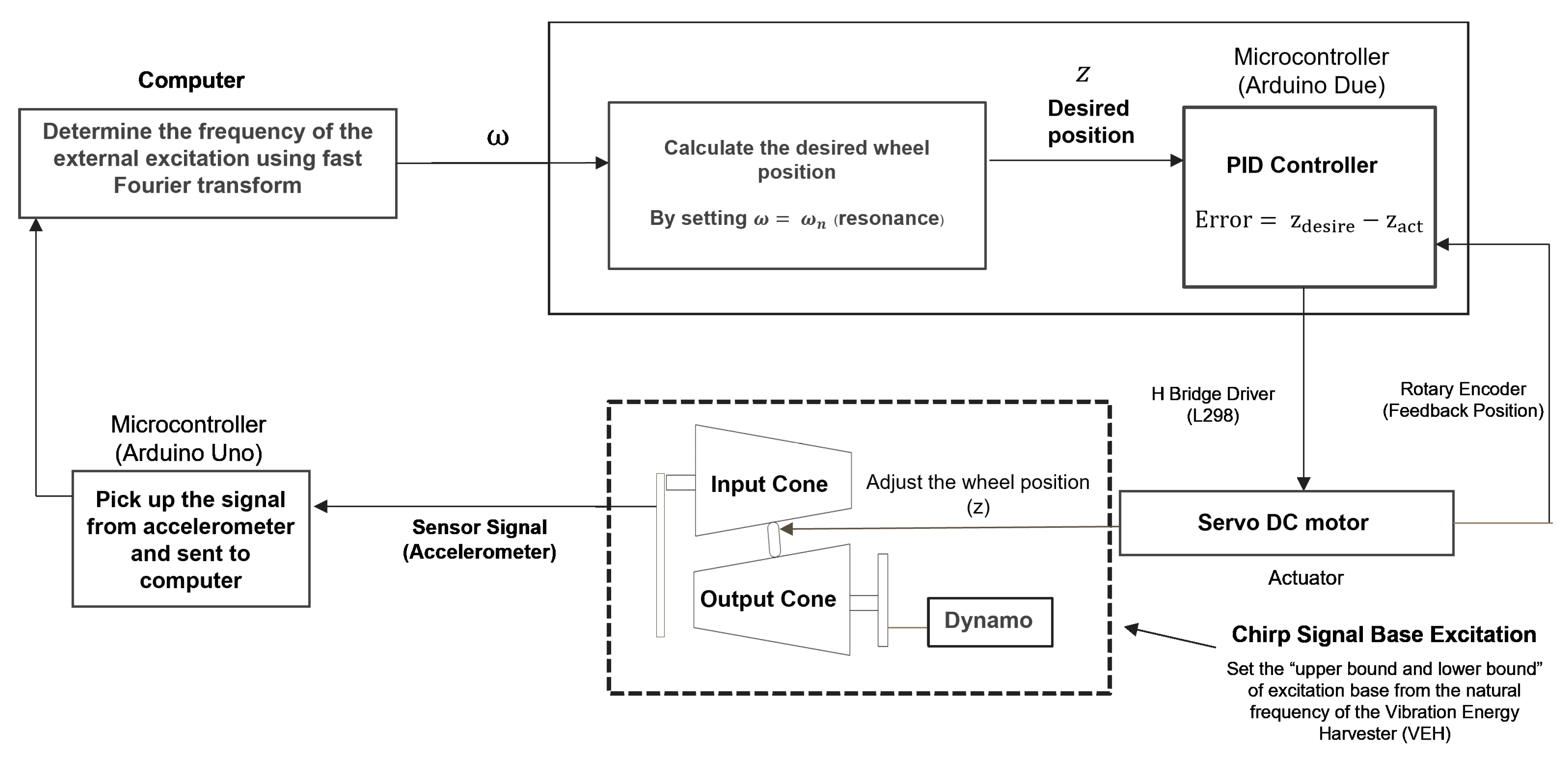
For the harmonic excitation, the appropriate wheel position is determined based on the resonance point. The autonomous self-tuning technique proposed in this research is illustrated in Figure 2. This approach begins by extracting the external excitation frequency from the sensor and computing the target wheel position. The computed result is then transmitted to the PID controller, which drives the DC motor to adjust the wheel position accordingly.
To conduct the experiment and investigate the energy harvester under chirp signal-based excitation, we begin by setting the excitation base as a chirp signal. The upper and lower limits of the excitation are defined on the basis of the natural frequency ω n of the vibration energy garvester (VEH). The proposed method is presented in Figure 2, while a block diagram of the closed-loop feedback used to adjust the wheel position is illustrated in Figure 3.

3.3. Control System Description

This section describes the control system configuration shown in Figure 3. The closed-loop control system for CVT tuning is illustrated in Figure 3. The excitation frequency is estimated in real time using an ADXL355 MEMS accelerometer mounted at the base. This sensor provides a digital three-axis acceleration output via the SPI interface, with a bandwidth of 0–1500 Hz . Its high accuracy and low-noise performance make it suitable for low-frequency vibration detection without requiring any analog signal conditioning.
The estimated excitation frequency is fed into a PID controller implemented on an Arduino Due board. The PID parameters are tuned using the Ziegler–Nichols method, with the gain values set to K p = 100, K i = 15, and K d = 10 to ensure fast settlement and minimal overshoot. As an actuator, a Maxon RE30 brushed DC motor (12 V, 30 W) is used. The motor is coupled with a ball screw mechanism to provide a precise linear displacement of the intermediate wheel in the cone CVT system. The motor is driven by a H-bridge driver, which accepts PWM signals from the microcontroller.
The PID controller effectively identifies the system excitation frequency by continuously adjusting the system’s response to match the excitation. The PID controller adapts to changes in the excitation frequency and minimizes tracking errors. The PID control system may experience delays, especially when the system has to respond to rapidly changing or unpredictable excitations. These delays happen because it takes time for the system to process feedback and make adjustments. To address this, efforts are made to reduce control latency by improving the system design, including optimizing the control and feedback loops to speed up the response time. However, completely eliminating these delays is challenging. In the future, advanced techniques like adaptive PID or model predictive control will be able to help the system predict and adjust for delays more effectively in real time, which will ensure that the system maintains optimal energy harvesting efficiency despite varying or non-stationary excitations.

4. Mathematical Modeling

A schematic of the main structure of the proposed system is illustrated in Figure 4. The main structure of the energy harvester system is represented by a spring attached vertically to the horizontally positioned pendulum stem, with the excitation occurring through direct resonance.

4.1. Harmonic Excitation

A vertical external force stimulates the system,
y = Y e i ω t
and the system enters the resonance state when ω = ω n , where ω n is the natural frequency of the pendulum-CVT system.
The kinematic energy K of the system is
K = K c v t + K b
where
K c v t = I c i θ ˙ i 2 + I c o + I f w G 2 θ ˙ i 2
K b = 1 2 m b y ˙ + l G θ ˙ i 2 + 1 2 I b θ ˙ i 2
where K c v t is the rotational kinematic energy, K b is the kinematic energy of the pendulum stem, I c i is the moment of inertia of the input cone, I c o is the moment of inertia of the output cone, I f w is the moment of inertia of the flywheel, K b is the kinematic energy of the pendulum stem, I b is the moment of inertia of the pendulum stem, l G is the length between the rotational point and the center of mass, and θ ˙ i is the angular velocity of the input cone. The potential energy of the system will be
V = 1 2 k l s θ i 2
where k is the spring constant.
From Kirchhoff’s circuit laws, we obtain the equation of an equivalent circuit as
k e θ ˙ i L d i d t + R L + R g i = 0
The Euler–Lagrange equation of this system is given by
L = K V
From this equation, we obtain
d d t L θ ˙ i L θ i = τ i
where the torque τ i created by the current flowing through the coil can be expressed as
τ i = c θ ˙ i k τ i
and k τ is the torque constant.
Then, the motion of the energy harvester (harvesting system) is
I b + J g + 2 I c i + 2 I c o + I f w G 2 + [ m b l G 2 ] θ ¨ i + c θ ˙ i + k τ i + k l s θ i = m b l G y ¨
The natural frequency ω n of the system is
ω n = k l s 2 I b + J g + 2 I c i + 2 I c o + I f w G 2 + m b l G 2
Thus, the natural frequency of the energy harvester can be adjusted in real time by adjusting its wheel position.
Electromagnetic harvesters operate at low frequencies [33], rendering the inductance of the generator negligible in comparison to its impact on the electric circuit. Therefore, the equation for the equivalent circuit can be written as
P L = i 2 R L = R L k e θ ˙ i R L + R g 2
We obtain the equation of this system, which is
I b + J g + 2 I c i + 2 I c o + I f w G 2 + m b l G 2 θ ¨ i + c θ ˙ i + k τ k e R L + R g θ ˙ i + k l s θ i = m b l G y ¨
The average electric power in the resonance state can be written as
P ω = ω n a v g = 1 2 m b l G ω n 2 Y C R L k t + k t R L 2

4.2. Chirp Signal Excitation

In order to conduct an experiment and investigation of the energy harvester under chirp signal base excitation, we begin by setting the excitation base as a chirp signal. The upper and lower bounds of the excitation are defined based on the natural frequency ω n of the vibration energy harvester (VEH). The proposed method is shown in Figure 2, in which a block diagram of the closed-loop feedback used to adjust the wheel position is also illustrated.
The wheel position z and gear ratio G are then calculated. The experiment focuses on how the system responds to the chirp signal base excitation and observes the differences between resonance control and non-resonance control.
By substituting the wheel position z = 0 mm with the gear ratio G in (15) and (16), we can obtain the natural frequency, which is ω min n = 3.461   rad / s and ω min n 2 = 11.978   rad / s . In the same way, when the wheel position is z = 700   mm , we obtain ω max n = 8.278   rad / s and ω max n 2 = 68.525   rad / s .
The lower or upper bounds will be applied if the excitation’s frequency in (17) is not in this range. Accordingly, the tuning algorithm is considered:
ω 2 = max 11.978 , min 68.525 , min 2 t 2 , 100
From this equation for the frequency tuning algorithm (resonance control), three cases can be divided, which are as follows:
(1)
0 < λ t ω min n
In this case, λ t is less than or equal to ω min n , so this case is “out of the tuning range”. The natural frequency of the system is set to ω min n = 3.461   rad / s , and the time in this case is 0 < t 1.73   s .
(2)
ω min n < λ t < ω max n
In this case, λ t is “in the tuning range”, and we assume that the natural frequency will be in real time. Then, we can set the excitation frequency ( ω ) = natural frequency ( ω n ) (13) 3.461 < ω ( t ) < 8.278   rad / s , and the time in this case is 1.73 < t < 4.139   s .
(3)
λ t ω max n
In this case, λ t is greater than or equal to ω max n . This case is “out of the tuning range”. Then, we set the natural frequency of the system to ω max n = 8.278   rad / s , and the time in this case is 4.139 < t < 5   s . From the equation for the frequency tuning algorithm (non-resonance control), we set z = 100   mm and G = 2.9 , and the time in this case is 0 < t < 5   s .
From the resonance and non-resonance control, we substitute all the parameters in (15) and solve it by using MATLAB ODE45, which allows us to observe the differences in the responses of the system between resonance and non-resonance control.

5. Numerical Simulation

Numerical simulations were conducted using MATLAB with the ODE45 solver in order to generate data for a dynamical analysis of the system. Some parameters were based on [14], with modifications to fit the proposed system. The simulation parameters are shown in Table 2.

5.1. Harmonic Excitation

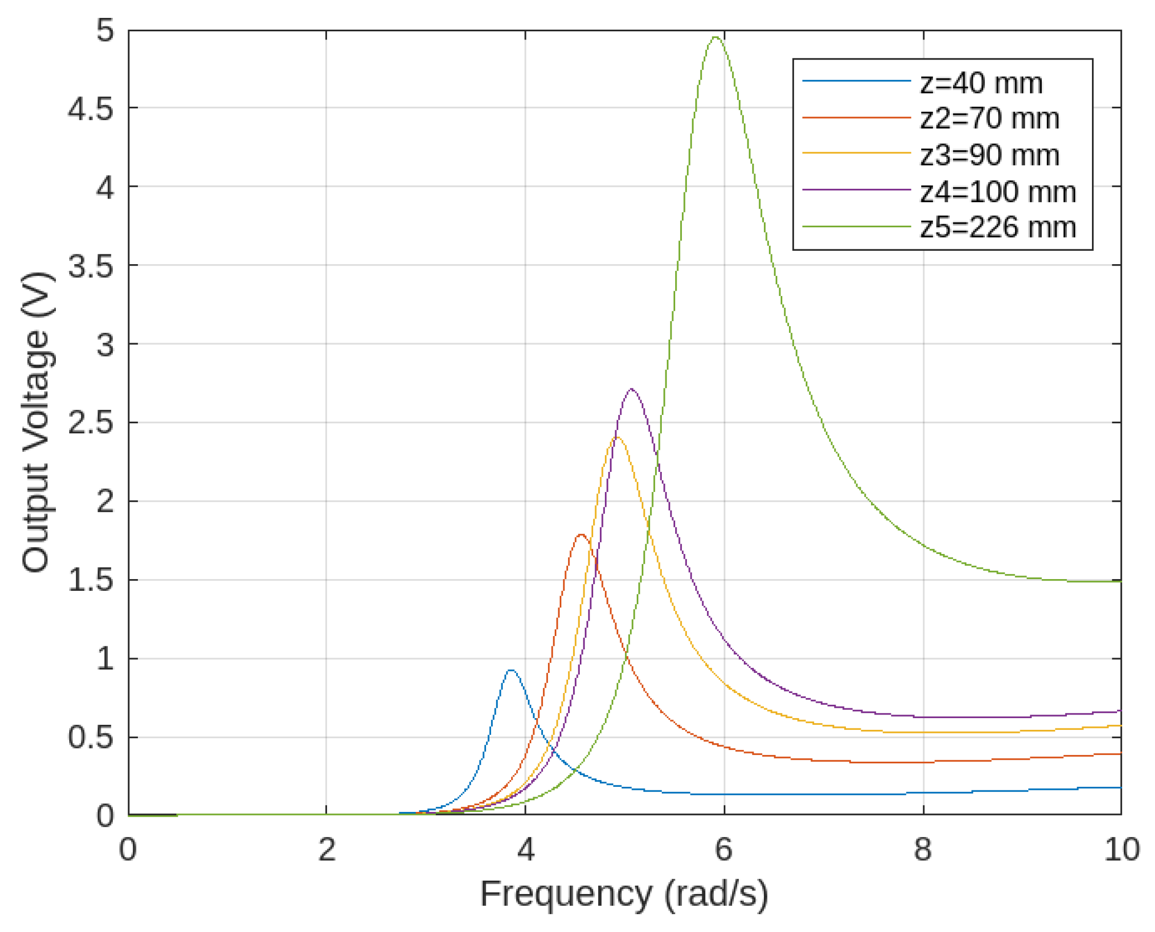
Figure 5 shows that adjusting the external excitation frequency to match the system’s natural frequency induces resonance, leading to the highest average power generation. Additionally, as the wheel position increases while maintaining resonance, the peak average power output also rises. This highlights the importance of optimizing the wheel position to enhance energy harvesting efficiency, making it a critical factor in tuning system performance. Furthermore, when the wheel position reaches 700 mm, the system exhibits a wider bandwidth, effectively expanding the tunable frequency range. In the graph, it is evident that increasing the value of z leads to an increase in both the peak voltage and the bandwidth.
Figure 6 illustrates the relationship between the system’s natural frequencies, ω n , and the wheel position z for various values of the spring constant k. As observed in the figure, the spring constant can be modified during experiments by selecting springs with different stiffness characteristics. The results indicate that the system’s natural frequency rises as the wheel moves further. Additionally, a higher spring constant expands the tunable frequency range, with its influence being particularly significant in the lower-frequency region.
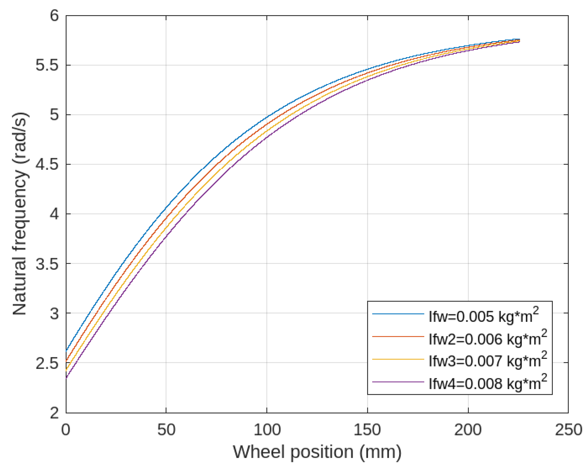
Figure 7 depicts the relationship between the system’s natural frequency (rad/s) and the wheel displacement z (mm) for various values of the flywheel’s moment of inertia. During the experiments, the moment of inertia can be modified by using flywheels with different inertia values. The results indicate that the natural frequency increases as the wheel position moves further. Additionally, a higher moment of inertia expands the tunable frequency range, with its impact being particularly significant in the lower-frequency region.
Figure 8 presents the simulated voltage output from the harvester model under sinusoidal base excitation. The waveform appears nearly sinusoidal due to the assumption of idealized system components, such as no electrical losses, linear damping, and ideal CVT responses. In practical implementations, however, this waveform may exhibit distortions due to mechanical friction and controller-induced nonlinearity.
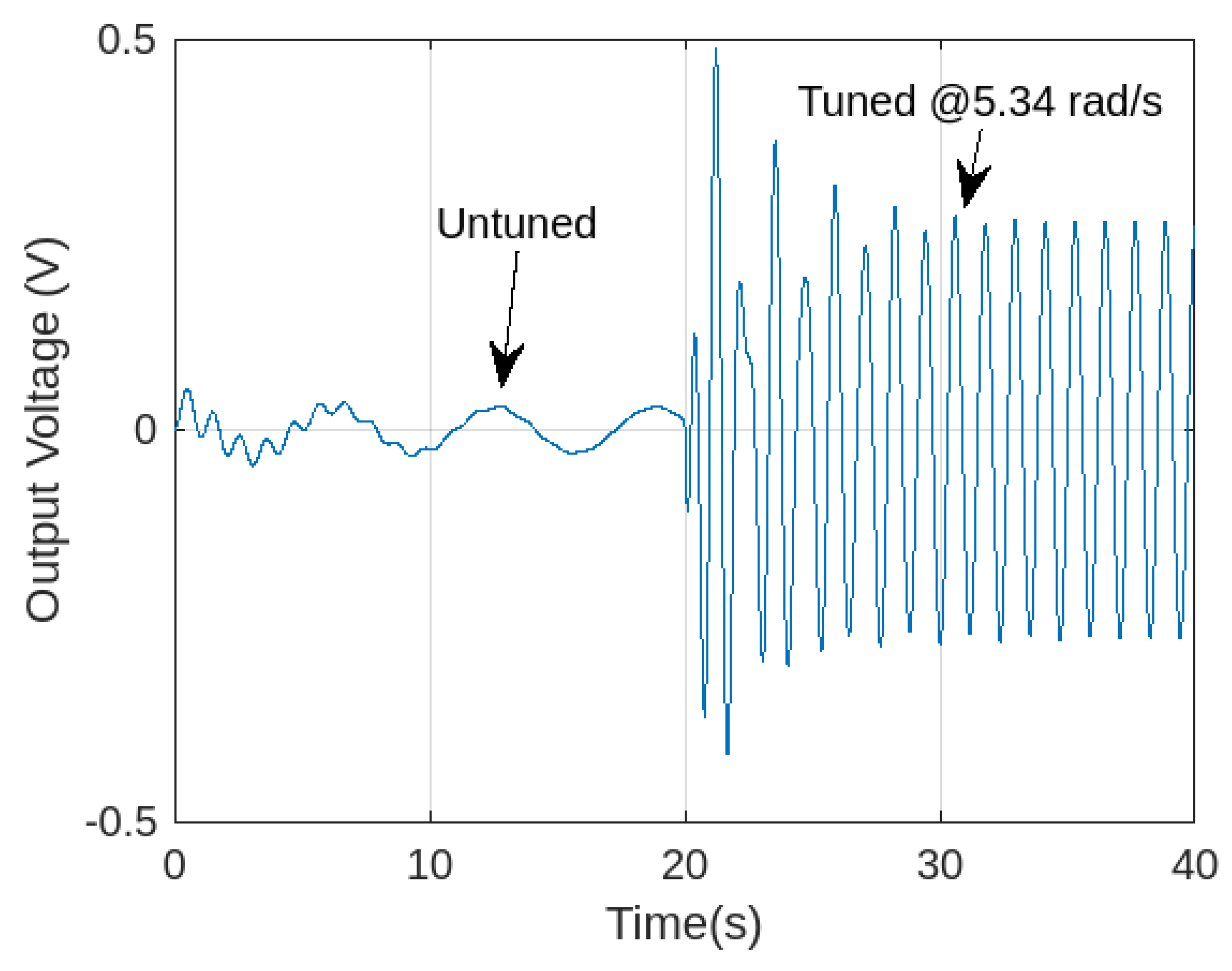
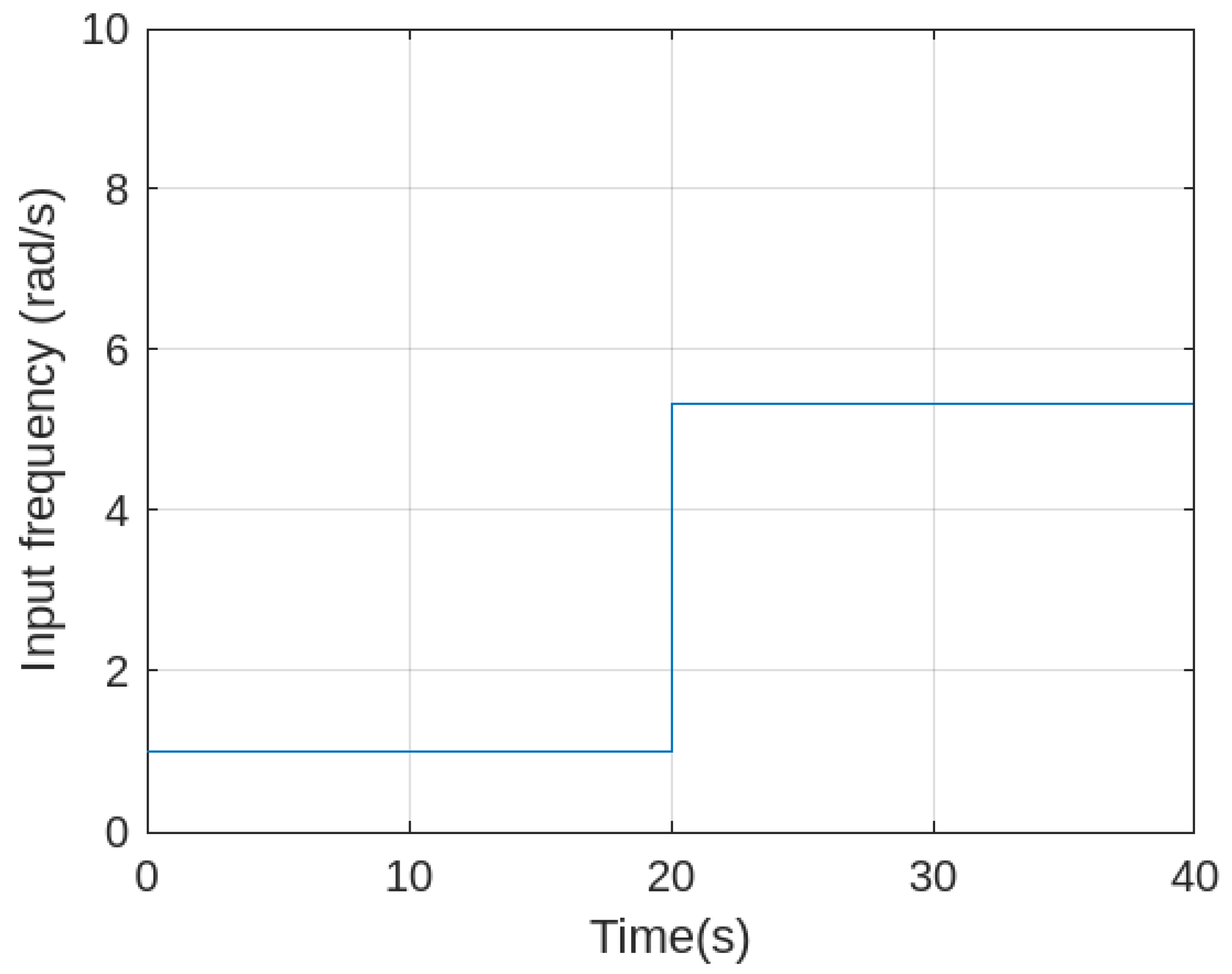
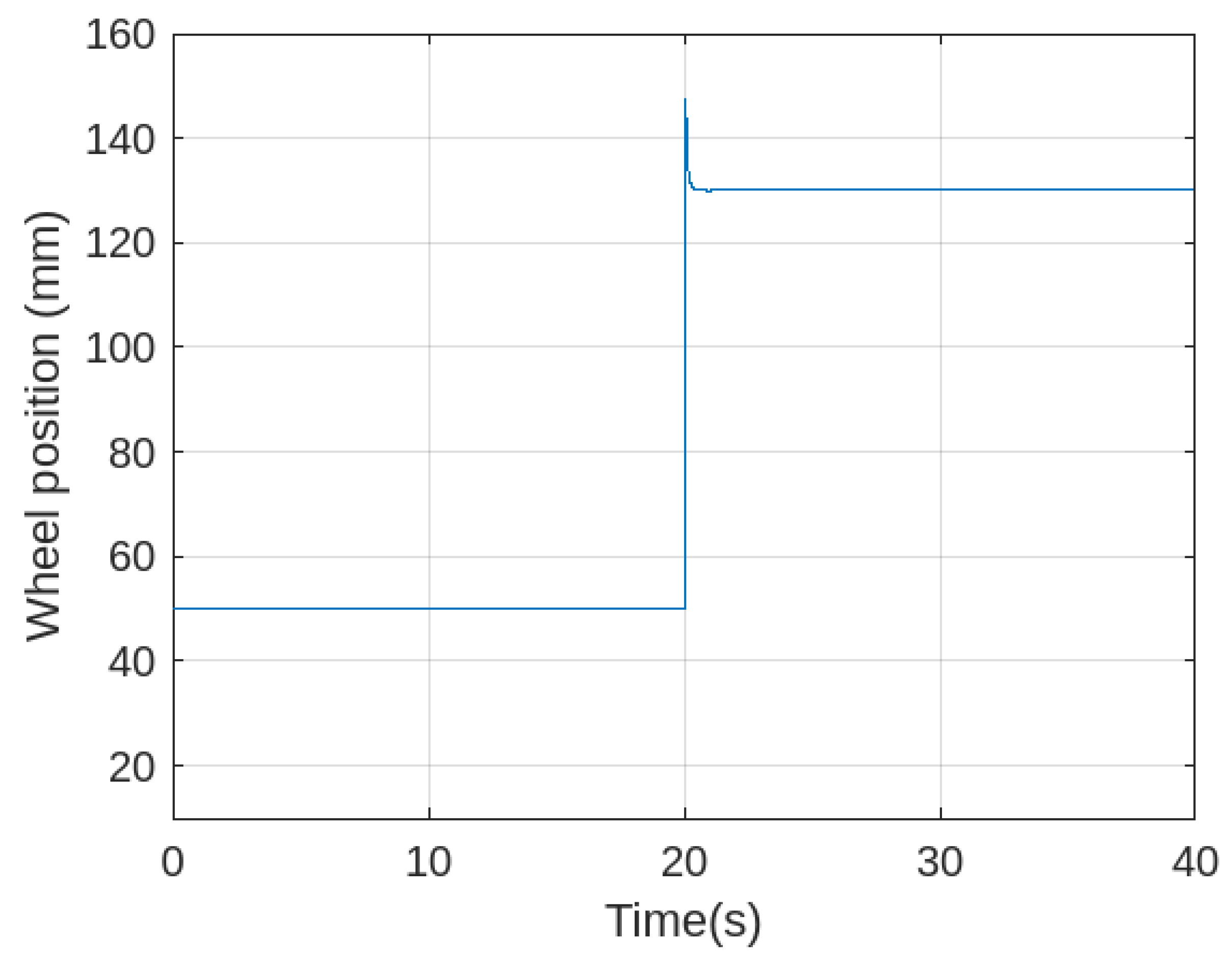
Figure 9 also illustrates the response of the energy harvesting system when the wheel is repositioned in real time using PID control. Initially, the system is excited at a frequency of 1 rad / s , with the wheel starting at a position of 50 mm , which does not match the natural frequency of the harvester. After t = 20   s , the external excitation frequency is changed to 5.34   rad / s , and the PID controller is activated. The servo motor adjusts the wheel position accordingly, and by t = 22   s , the system reaches resonance, resulting in an approximate tenfold increase in the voltage output.
As seen in Figure 9 and Figure 10, after t = 22   s , both the excitation frequency and wheel position stabilize at their new values. The sharp increase in the wheel position indicates active regulation by the PID controller in response to the external frequency shift. The stabilization implies that the control system has successfully reached a new equilibrium.

5.2. Chirp Signal Base Excitation

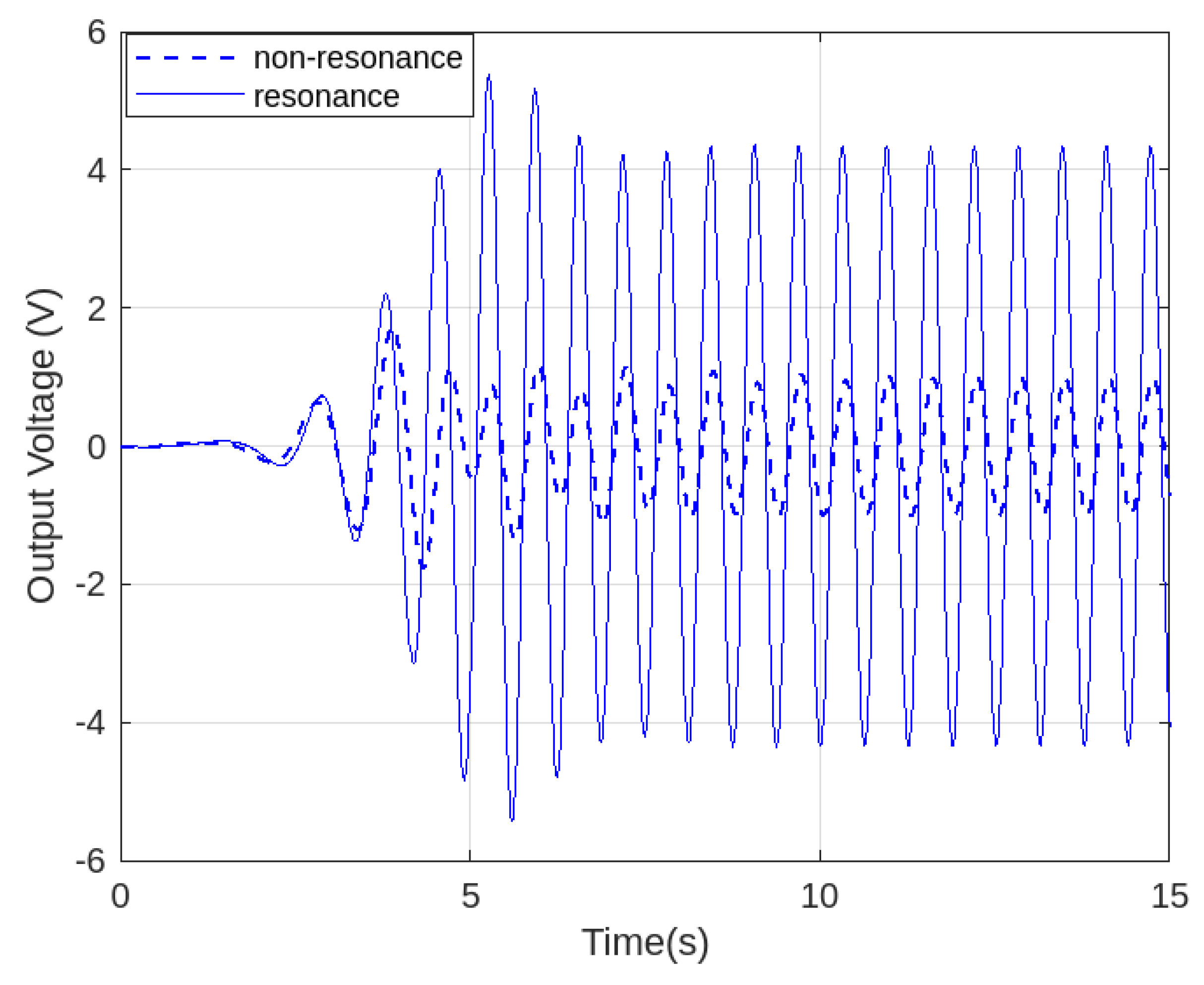
Figure 11 shows that resonance control is more effective in sustaining the resonance state than non-resonance control. The control input is also based on a simulated response under ideal excitation. While the waveform appears smooth and periodic, this reflects the steady-state performance of the PID-controlled actuator once resonance is achieved. In real hardware, this signal may contain higher-frequency content due to sensor noise, ball screw backlash, and actuation delay. In the graph, the solid line represents resonance control, while the dotted line corresponds to non-resonance control. In addition, the system exhibits a wider bandwidth, which enhances its overall efficiency.
Similarly, in Figure 12, the solid line denotes resonance control, whereas the dotted line represents non-resonance control over an extended period. The results clearly show that the resonance state maintains an optimal voltage level after t = 5   s , demonstrating the effectiveness of resonance control in achieving stable performance. Overall, the resonance control mechanism enhances the system’s ability to sustain oscillations at resonance, resulting in a significantly higher output voltage than the non-resonance case. This confirms that resonance control improves energy harvesting efficiency by maximizing the voltage output over time.
Although the output waveform appears sinusoidal, this is expected given the harmonic nature of the excitation and the system’s resonance response. However, this does not imply the inefficiency of the control loop but rather reflects the tuned dynamics. The PID controller successfully maintains the system at resonance, where sinusoidal energy transfer is most efficient.
In order to assess the performance of the proposed energy harvester, this research utilizes non-dimensional evaluation criteria, as outlined by
J max = max V i ( t ) max V uncontrolled ( t ) J rms = V i ( t ) V uncontrolled ( t )
where J max is a criterion that indicates the maximum amplitude ratio between the controlled and uncontrolled voltage signals, max V i ( t ) is the maximum absolute value of the controlled voltage signal, max V uncontrolled ( t ) is the maximum absolute value of the uncontrolled voltage signal, J rms is a criterion that indicates the RMS ratio between the controlled and uncontrolled voltage signals, V i ( t ) is the RMS value of the controlled voltage signal, and V uncontrolled ( t ) is the RMS value of the uncontrolled voltage signal. The performance index non-dimensional evaluation criteria are shown in Table 3

6. Conclusions

This paper proposes a pendulum directly coupled to cone CVT to facilitate the automatic adjustment of its natural frequency. A numerical approach was employed to assess the performance of the proposed energy harvester. However, this study is limited to numerical simulations and has not yet been validated through physical experimentation. Real-world challenges, such as sensor noise, mechanical backlash, and thermal effects, were not considered in the model. Key limitations include the absence of physical validation, simplified idealized components in the simulations, and minimized but not eliminated control latency. The influence of varying spring constant values (k) on energy harvesting was examined by modifying the spring characteristics. Furthermore, the effect of tuning the external excitation frequency to match the natural frequency was also investigated. The results revealed that increasing the wheel position at the resonance point resulted in the highest average power output. Through the autonomous self-tuning method, after t = 22 s , an abrupt change in the external excitation frequency prompted the harvester to automatically adjust its natural frequency to match this shift. Performance testing is crucial for assessing the system’s response to real-world excitation conditions. Overall, the root-mean-square (RMS) output voltage increased by a factor of 2.112 when comparing the resonance-controlled vibration energy harvester to its non-resonance-controlled counterpart. Additionally, the resonance-controlled vibration energy harvester demonstrated a 1.9764-fold increase in the maximum output voltage relative to the non-resonance-controlled vibration energy harvester. Future work will focus on developing a physical prototype for validation, implementing advanced control algorithms like adaptive PID or model predictive control, integrating vibration suppression with energy harvesting, and incorporating AI-based frequency prediction to reduce response delays.

Author Contributions

Conceptualization, C.U. and S.P.; methodology, C.U., S.P. and N.T.M.; software, C.U. and S.P.; validation, M.A.S.K. and I.M.; formal analysis, S.P. and K.Y.; investigation, K.Y.; resources, K.Y.; data curation, S.P.; writing—original draft preparation, C.U.; writing—review and editing, S.P. and K.Y.; supervision, K.Y.; project administration, K.Y. All authors have read and agreed to the published version of the manuscript.

Funding

This research received no external funding.

Data Availability Statement

The original contributions presented in this study are included in the article. Further inquiries can be directed to the corresponding author.

Conflicts of Interest

The authors declare no conflicts of interest.

References

  1. Ahmed, S.; Mahmud, A.; Rahman, M.M.; Khan, M.F.; Saidur, R. A review on the integration of radiative cooling and solar energy harvesting. Mater. Today Energy 2021, 21, 100776. [Google Scholar] [CrossRef]
  2. Vullers, R.J.M.; Van Schaijk, R.; Doms, I.; Van Hoof, C.; Mertens, R. Micropower energy harvesting. Solid-State Electron. 2009, 53, 684–693. [Google Scholar] [CrossRef]
  3. Beeby, S.P.; Tudor, M.J.; White, N.M. Energy harvesting vibration sources for microsystem applications. Meas. Sci. Technol. 2006, 17, R175–R195. [Google Scholar] [CrossRef]
  4. Marszal, M.; Witkowski, B.; Jankowski, K.; Perlikowski, P.; Kapitaniak, T. Energy harvesting from pendulum oscillations. Int. J. Non-Linear Mech. 2017, 94, 251–256. [Google Scholar] [CrossRef]
  5. Chen, J.; Xu, C.; Zhang, W.; Wu, L. Pendulum energy harvesters: A review. Energies 2022, 15, 8674. [Google Scholar] [CrossRef]
  6. Lenci, S.; Brocchini, M.; Lorenzoni, C. Experimental rotations of a pendulum on water waves. J. Appl. Mech. 2012, 79, 011007. [Google Scholar] [CrossRef]
  7. Wang, T. Pendulum-Based Vibration Energy Harvesting: Mechanisms, Transducer Integration, and Applications. Energy Convers. Manag. 2023, 276, 116469. [Google Scholar] [CrossRef]
  8. Jiang, W.; Han, X.; Chen, L.; Bi, Q. Improving Energy Harvesting by Internal Resonance in a Spring-Pendulum System. Acta Mech. Sin. 2020, 36, 618–623. [Google Scholar] [CrossRef]
  9. Abohamer, M.K.; Awrejcewicz, J.; Starosta, R.; Amer, T.S.; Bek, M.A. Influence of the Motion of a Spring Pendulum on Energy-Harvesting Devices. Appl. Sci. 2021, 11, 8658. [Google Scholar] [CrossRef]
  10. He, C.H.; Amer, T.S.; Tian, D.; Abolila, A.F.; Galal, A.A. Controlling the Kinematics of a Spring-Pendulum System Using an Energy Harvesting Device. J. Low Freq. Noise Vib. Act. Control 2022, 41, 1234–1257. [Google Scholar] [CrossRef]
  11. Pham, P.T.; Nguyen, Q.C. Dynamic model of a three-dimensional flexible cantilever beam attached to a moving hub. In Proceedings of the 2017 11th Asian Control Conference (ASCC), Gold Coast, QLD, Australia, 17–20 December 2017; IEEE: Tokyo, Japan, 2017; pp. 2744–2749. [Google Scholar] [CrossRef]
  12. Covaci, C.; Gontean, A. Piezoelectric energy harvesting solutions: A review. Sensors 2020, 20, 3512. [Google Scholar] [CrossRef] [PubMed]
  13. Yang, Y.; Liu, C.; Lai, S.K.; Chen, Z.; Chen, L. Frequency-dependent equivalent impedance analysis for optimizing vehicle inertial suspensions. Nonlinear Dyn. 2025, 113, 9373–9398. [Google Scholar] [CrossRef]
  14. Punyakaew, S. Adaptively tuned vibration absorber using cone-based continuously variable transmission. Cogent Eng. 2022, 9, 2102044. [Google Scholar] [CrossRef]
  15. Shi, B.; Dai, W.; Yang, J. Performance enhancement of vehicle suspension system with geometrically nonlinear inerters. Arch. Appl. Mech. 2024, 94, 39–55. [Google Scholar] [CrossRef]
  16. Punyakaew, S.; Parnichkun, M. Vibration energy harvesting for low frequency using auto-tuning parametric rolling pendulum under exogenous multi-frequency excitations. Theor. Appl. Mech. Lett. 2020, 10, 448–455. [Google Scholar] [CrossRef]
  17. Brzeski, P.; Kapitaniak, T.; Perlikowski, P. Novel type of tuned mass damper with inerter which enables changes of inertance. J. Sound Vib. 2015, 349, 56–66. [Google Scholar] [CrossRef]
  18. Wang, F.C.; Wu, S.Y. Vibration control of an optical table employing mechatronic inerter networks. J. Vib. Control 2016, 22, 224–234. [Google Scholar] [CrossRef]
  19. Sun, J.Q.; Jolly, M.A.; Norris, M.T. Passive, adaptive and active tuned vibration absorbers—A survey. J. Sound Vib. 1995, 186, 475–489. [Google Scholar] [CrossRef]
  20. Hrovat, D.; Barak, P.; Rabins, M. Semi-active versus passive or active tuned mass dampers for structural control. J. Eng. Mech. 1983, 109, 691–705. [Google Scholar] [CrossRef]
  21. Rahimi, F.; Aghayari, R.; Samali, B. Application of tuned mass dampers for structural vibration control: A state-of-the-art review. Civ. Eng. J. 2020, 6, 1622–1651. [Google Scholar] [CrossRef]
  22. Renno, J.M.; Daqaq, M.F.; Inman, D.J. On the Optimal Energy Harvesting from a Vibration Source. J. Sound Vib. 2009, 320, 386–405. [Google Scholar] [CrossRef]
  23. Kadjie, A.N.; Woafo, P. Effects of Springs on a Pendulum Electromechanical Energy Harvester. Theor. Appl. Mech. Lett. 2014, 4, 063001. [Google Scholar] [CrossRef]
  24. Graves, J.; Kuang, Y.; Zhu, M. Pendulum Energy Harvester with Torsion Spring Mechanical Energy Storage Regulator. Sens. Actuators A Phys. 2022, 339, 113505. [Google Scholar] [CrossRef]
  25. Wu, Y.; Qiu, J.; Kojima, F.; Ji, H.; Xie, W.; Zhou, S. Design Methodology of a Frequency Up-Converting Energy Harvester Based on Dual-Cantilever and Pendulum Structures. AIP Adv. 2019, 9, 045114. [Google Scholar] [CrossRef]
  26. Wang, T.; Zhu, S. Analysis and Experiments of a Pendulum Vibration Energy Harvester with a Magnetic Multi-Stable Mechanism. IEEE Trans. Magn. 2022, 58, 8002507. [Google Scholar] [CrossRef]
  27. Zhang, A.; Sorokin, V.; Li, H. Energy Harvesting Using a Novel Autoparametric Pendulum Absorber-Harvester. J. Sound Vib. 2021, 499, 116014. [Google Scholar] [CrossRef]
  28. Li, M.; Deng, H.; Zhang, Y.; Li, K.; Huang, S.; Liu, X. Ultra-low frequency eccentric pendulum-based electromagnetic vibrational energy harvester. Micromachines 2020, 11, 1009. [Google Scholar] [CrossRef]
  29. Uttachee, C.; Punyakaew, S.; Mai, N.T.; Hashikura, K.; Kamal, M.A.S.; Murakami, I.; Yamada, K. Tunable Pendulum Energy Harvester Using Cone Continuously Variable Transmission. In Proceedings of the 2024 21st International Conference on Electrical Engineering/Electronics, Computer, Telecommunications and Information Technology (ECTI-CON), Khon Kaen, Thailand, 27–30 May 2024; pp. 1–5. [Google Scholar] [CrossRef]
  30. Sarker, M.R.; Julai, S.; Sabri, M.F.; Said, S.M.; Islam, M.M.; Tahir, M. Review of piezoelectric energy harvesting system and application of optimization techniques to enhance the performance of the harvesting system. Sens. Actuators A Phys. 2019, 300, 111634. [Google Scholar] [CrossRef]
  31. Yang, T.; Zhou, S.; Fang, S.; Qin, W.; Inman, D.J. Nonlinear vibration energy harvesting and vibration suppression technologies: Designs, analysis, and applications. Appl. Phys. Rev. 2021, 8, 031317. [Google Scholar] [CrossRef]
  32. Dotti, F.E.; Reguera, F.; Machado, S.P. Rotations of the parametric pendulum excited by a reciprocating motion with a view on energy harvesting. In International Symposium on Dynamic Problems of Mechanics; Springer International Publishing: Cham, Switzerland, 2017; pp. 385–397. [Google Scholar] [CrossRef]
  33. Lee, B.C.; Chung, G.S. Design and fabrication of low-frequency driven energy harvester using electromagnetic conversion. Trans. Electr. Electron. Mater. 2013, 14, 143–147. [Google Scholar] [CrossRef]
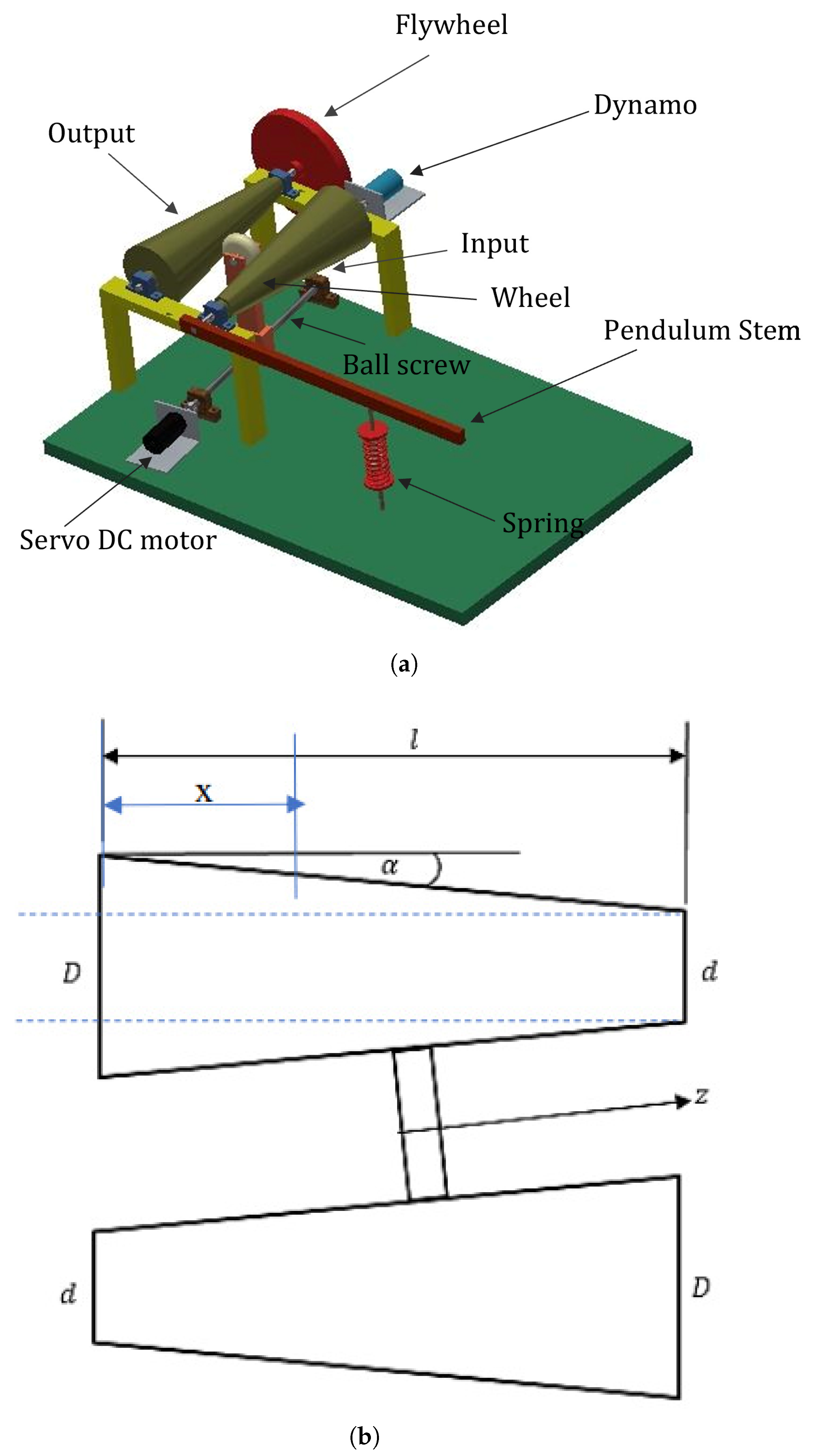
Figure 1. (a) Isometric view of cone CVT. (b) Schematic model of cone CVT [5].
Machines 13 00365 g001
Figure 2. Diagram of system and proposed method for self-tuning technique and chirp signal base excitation.
Machines 13 00365 g002
Figure 3. Diagram of closed-loop feedback in this system.
Machines 13 00365 g003
Figure 4. Schematic of the main structure of the main energy harvester system.
Machines 13 00365 g004
Figure 5. The output voltage versus frequency at different wheel positions.
Machines 13 00365 g005
Figure 6. The natural frequency versus wheel position under different spring constants.
Machines 13 00365 g006
Figure 7. The natural frequency versus wheel position under different moments of inertia of the flywheel.
Machines 13 00365 g007
Figure 8. Time response of the closed-loop system output voltage.
Machines 13 00365 g008
Figure 9. Time response of the frequency under closed-loop PID control.
Machines 13 00365 g009
Figure 10. Time response of the intermediate wheel position under closed-loop PID control.
Machines 13 00365 g010
Figure 11. Time response of the closed-loop system output voltage between resonance and non-resonance control at ( t = 5   s ).
Machines 13 00365 g011
Figure 12. Time response of the closed-loop system voltage between resonance and non-resonance control at ( t = 15   s ) .
Machines 13 00365 g012
Table 1. Comparison with the proposed active CVT + PID tuning system.
MethodAdvantagesDisadvantages
Beeby et al. [3] (microscale systems)More scalable for MEMS applicationsLimited adaptability and low output in dynamic environments
Shi et al. [15] (system classification)Offers a broad theoretical frameworkNo practical tuning or real-time adaptability
Punyakaew et al. [16] (passive auto-tuning)Simpler and energy-efficient, no active control requiredCannot adapt to rapidly changing or wide-range inputs
Yang et al. [31] (nonlinear systems)Broader bandwidth and multifunctionalityHarder to control precisely, less stable in real time
Dotti et al. [32] (parametric pendulum)Useful in identifying stable excitation zonesNo real-time response or control flexibility
Proposed (active CVT + PID)real-time tuning, wide adaptability, precise resonance tracking, multifunctional usePID control may face challenges under rapidly changing or nonlinear vibration conditions
Table 2. Parameter values used for MATLAB simulation.
SymbolsValuesUnit
I c i 0.00475 kg · m 2
I c o 0.00475 kg · m 2
I f 0.005 kg · m 2
I b 0.0266 kg · m 2
J g 8.3 × 10 6 kg · m 2
k s 200 N / m
m b 2 kg
c0.028
l s 0.2 m
l g 0.2 m
l c 0.7 m
k τ 0.5 N · m
k b 0.5 V · rad 1 · s 1
D0.22665 m
d0.04 m
d w 0.074 m
R L 2 Ω
R g 2 Ω
Table 3. Performance index non-dimensional evaluation criteria.
Performance IndexTunedUntuned
RMS voltage2.01090.6756
MAXIMUM voltage5.37221.7260
Disclaimer/Publisher’s Note: The statements, opinions and data contained in all publications are solely those of the individual author(s) and contributor(s) and not of MDPI and/or the editor(s). MDPI and/or the editor(s) disclaim responsibility for any injury to people or property resulting from any ideas, methods, instructions or products referred to in the content.