Article

An Investigation on the Mechanical Characteristics of Railway Locomotive Axle Box Bearings with Sensor-Embedded Slots

1
College of Mechanical and Vehicle Engineering, Changsha University of Science and Technology, Changsha 410114, China
2
Hunan Provincial Key Laboratory of High-Performance Intelligent Manufacturing Key Technologies for Mechanical Equipment, Changsha 410114, China
*
Author to whom correspondence should be addressed.
Machines 2025, 13(5), 358; https://doi.org/10.3390/machines13050358
Submission received: 8 March 2025 / Revised: 15 April 2025 / Accepted: 16 April 2025 / Published: 25 April 2025
(This article belongs to the Section Machine Design and Theory)

Abstract

:
The intelligent bearing with an embedded sensor is a key technology to realize the running state monitoring of railway locomotive axle box bearings at the source end. To investigate the mechanical properties of axle box bearings with embedded sensor slots, based on nonlinear Hertzian contact theory and the bearing fatigue life theory, a mechanical equivalent analysis model with a virtual mandrel is established for double-row tapered roller bearings used in axle boxes with sensor-embedded slots, which integrally considers the effects of external forces. After verifying the mesh independence before and after embedding the sensor slots, the contact load of tapered rollers calculated by the mechanical model is compared with the theoretical solution based on Hertz contact which verifies the validity of the model from the perspective of contact load. The results show that adjusting the grooving depth and axial position has a significant effect on the local stress peak, and an excessive grooving depth or inappropriate axial position will trigger fatigue damage. This study provides a theoretical basis for analyzing the mechanical characteristics of sensor-embedded slots used in railway locomotive axle box bearings.

1. Introduction

During the operation of high-speed trains, an axle box bearing is a key component that bears complex loads. Their operational condition directly determines the train’s running safety and stability performance. Double-row tapered roller bearings are widely adopted in high-speed train axle boxes due to their superior radial and axial load-carrying capacity. However, traditional bearing condition monitoring methods exhibit inherent limitations, as they are incapable of real-time operational status tracking or providing effective early warnings for potential failures. With the continuous advancement of intelligent technologies, embedded sensors have become an important tool for real-time monitoring applications. However, when designing the sensor-embedded slots, their dimensions and positions may alter the stress state and distribution within the bearing, consequently affecting its fatigue life performance. Therefore, investigating the effects of sensor-embedded slots on bearing mechanical performance is of significant theoretical and practical importance.
In recent years, scholars worldwide have conducted extensive research on the contact characteristics of rolling bearings. Li et al. [1] established a five-degree-of-freedom nonlinear dynamic model for double-row angular contact ball bearings, considering the influence of various mechanical factors on bearing performance. Based on nonlinear Hertzian contact theory, Lei et al. [2] established a time-varying stiffness model for angular contact ball bearings, proposed a dynamic calculation method for bearings with compound faults in the inner and outer races, and investigated the vibration responses of compound-fault bearings under different parameters and operating conditions. Zhang et al. [3] established a dynamic model for all-ceramic angular contact ball bearings, incorporating the slip behavior of rolling elements. The model was used to analyze the vibration characteristics and periodicity of the bearing system. Li et al. [4] analyzed the effects of operating conditions, such as speed and radial load, on the dynamic contact behavior of four-point contact ball bearings. Tu et al. [5] employed the fourth-order Runge–Kutta method to solve the system of differential equations, obtaining the contact loads between the inner ring and rollers under a varying amplitude and frequency, as well as the dynamic contact characteristics of the cage under different forms of periodic load fluctuations. Lei et al. [6] proposed a dynamic calculation method for angular contact ball bearings with local defects on the outer ring based on Hertzian contact theory and impact force functions, studying the vibration characteristics of faulty ball bearings and validating the results experimentally. Luo et al. [7] studied the collision and contact characteristics between the cage and rolling elements, as well as the influence of bearing load and speed on the cage’s contact behavior through dynamic simulations. Chu et al. [8] established a high-speed train trailer rigid–flexible coupling dynamic model that considered both axle box bearings and the braking system, simulating the vibration, load, and internal contact characteristics of the axle box bearing under different curve geometries and braking conditions. The aforementioned studies conducted an in-depth analysis of contact loads and stresses in rolling element bearings, with a particular emphasis on ball bearing applications.
Li et al. [9] proposed a quasi-static analysis model with five degrees of freedom, studying the influence of combining loads on bearing stiffness coefficients. Gu et al. [10] developed a dynamic wear simulation model for paired angular contact ball bearings and formulated a generalized time-varying, piecewise nonlinear dynamic model to accurately investigate their dynamic characteristics. Liu [11] proposed a finite element model to study the influence of horizontal and inclined subsurface cracks on the contact characteristics of roller bearings. Xu et al. [12] integrated a clearance fit model and a bearing stiffness analytical model into a spindle finite element (FE) model to develop a dynamic model for multi-support rotor systems. Through this framework, they rigorously investigated the effects of fit clearance, radial force, and axial force on both the vibration behavior and contact interface characteristics of rolling bearings within the system. Tonazzi et al. [13] investigated the contact stress and strain field distribution in rolling bearings subjected to high-load oscillatory motion, specifically focusing on the regime characterized by extreme contact pressures and localized deformations. Shah et al. [14] developed a contact stress modeling framework for spherical roller bearings and subsequently evaluated their fatigue life under dynamic loading conditions. Talbot et al. [15] developed a four-object elastic friction contact program for bearing boundary element methods, simulating the load distribution of four-row tapered roller bearings in a rolling mill. Liu [16] proposed an analytical method considering the axial preload and contact angle, obtaining the load distribution and stiffness coefficients of preloaded angular contact ball bearings under combined loads. Guo et al. [17] developed a dynamic model of axle box bearings under time-varying speed conditions, incorporating vehicle–track dynamic interactions and explicitly accounting for inner/outer raceway faults. Wang [18] developed a dynamic model for ball bearings with an emphasis on structural flexible deformation, examined the interaction mechanisms between the bearing seat ring and other components, and explored the influence of structural flexibility on the dynamic behavior of bearings. The aforementioned investigations systematically examined the effects of loading conditions, subsurface cracks, and assembly misalignment on contact characteristics of rolling bearing systems.
The prediction of fatigue life is an important means to evaluate its service life. Numerous researchers have made valuable contributions to the analysis of bearing fatigue life. Yu et al. [19] established an improved nonlinear fatigue damage accumulation model accounting for variable loading conditions in bearings. Paulson et al. [20] investigated the remaining life of refurbishing bearings proportional to the regrinding depth. In addition to tapered roller bearings, cylindrical roller bearings are also utilized in axle box applications. Warda et al. [21] predicted the fatigue life of radial cylindrical roller bearings considering the influence of ring misalignment by using Lundberg and Palmgren’s model. Cheng et al. [22], based on the bearing fatigue life theory, analyzed the influence of loads on the mechanical characteristics and fatigue life of the ball bearing. Li et al. [23] predicted the fatigue life of high-speed axle box bearings based on the generalized linear cumulative damage theorem under random loading conditions. Jin et al. [24] predicted the flange life by FE analysis and rotational bending fatigue tests. Yu et al. [25] conducted the probabilistic fatigue life prediction of rolling bearings considering the uncertainty of material parameters under constant and variable loads. Heng et al. [26] studied the dynamic characteristics of curvic couplings in rotor-bearing by 3D simplification and stiffness conversion. Cong et al. [27] developed a methodology for predicting fatigue crack initiation life in actual failed bearings under high-cycle rolling contact fatigue conditions. By considering the combined load effects, Jiang et al. [28] analyzed the contact stiffness and fatigue life of deep-groove ball bearings. The results are beneficial for assembly processes. The aforementioned studies demonstrate that the fatigue life prediction of rolling bearings holds critical importance in both bearing design and operational maintenance. Current research efforts have predominantly focused on a fatigue life assessment of conventional bearing components, while limited attention has been given to lifespan prediction methodologies addressing slot effects in intelligent bearing systems.
In summary, a large body of research has focused on investigating the mechanical characteristics of conventional rolling bearings, including the analysis of contact load distribution, roller slip behavior, and vibration response. The exigency for real-time operational state monitoring of bearing internals necessitates the evolutionary progression toward cyber–physical integrated intelligent bearing architectures with embedded sensing capabilities, constituting an indispensable trajectory in prognostics and health management paradigms for rotating machinery systems. Sensor-embedded intelligent bearings are an inevitable trend of development. However, there is not enough theoretical and analytical basis for sensor-embedded bearings.
A real-time monitoring of equipment’s operational status is crucial for ensuring the safe operation of machinery, as well as advancing the design and manufacturing capabilities of high-performance critical components. However, traditional bearing monitoring systems are constrained by non-source-side detection methods, characterized by a challenging signal acquisition and poor signal quality, which significantly impede an accurate assessment of bearing service conditions. Current intelligent bearing configurations predominantly employ externally mounted or end-face-embedded sensing elements. There are some studies on the outer-ring-embedded slot structure in ball bearings, which can provide reference insights for the ring design of tapered roller bearings with sensor-embedded slots. However, the non-uniform axial wall thickness of tapered roller bearing outer rings renders conventional slot design methodologies inadequate, as the slot geometry, depth, and axial position exert fundamentally different impacts on structural life compared to standard bearings. It is worth noting that the influence of the position and depth of the sensor-embedded slot in the bearing outer ring on the bearing performance has not been thoroughly explored. The main contribution of this study is to guarantee that the strength and life of the bearing ring meet the requirements by adjusting the depth and position of the sensor-embedded slots Therefore, this study aims to fill this research gap and reveal the influence of the sensor pre-embedded slot on the contact characteristics and fatigue life of the double-row tapered roller bearings used in the axle boxes of high-speed trains through the establishment of an equivalent mechanical model of the bearings, so as to provide theoretical support for the design of the sensor-embedded bearings.

2. The Theoretical Model of Double-Row Tapered Roller Bearing

2.1. Bearing Contact Load

When considering external loads acting on the bearing, it is assumed that the bearing as a whole is subjected to a radial external load F r , an axial external load F a , an axial preload F p , and an external bending moment M , simultaneously. Furthermore, the rolling element is subjected to centrifugal force F c n j , as shown in Figure 1. Among them, n denotes the row where the roller is located, and j represents the roller number.
For a conical rolling element, the force relationship is shown in Figure 2. Among them, F o n j , F i n j , and F r n j represent the rolling element-outer raceway contact load, rolling element-inner raceway contact load, and the rolling element-large end rib contact load, respectively. μ f denotes the friction coefficients between the rolling element and the rib. F d j represents the drag force.
In the local coordinate system o n j x n j y n j z n j of a rolling element, the force equilibrium equation for the j-th rolling element in the n-row on the x n j o n j z n j plane can be established as follows [29]:
F o n j sin α o F i n j sin α i F r n j sin α f = 0 ,
F o n j cos α o F i n j cos α i + F r n j cos α f F c n j = 0 ,
where α i denotes the load angle between the roller and inner raceway, α o represents the load angle between the roller and outer raceway, and α f is the load angle between the roller and rib.
For an entire bearing, assuming Z is the number of rollers for each row [29], the equilibrium equations for the entire double-row tapered roller bearing are obtained as follows:
F r = n = 1 2 j = 1 Z F o n j cos α o cos φ j F a = n = 1 2 j = 1 Z k F o n j s i n α o M = n = 1 2 j = 1 Z k ( 1 2 d c F o n j cos φ j cos α o + r m F o n j cos φ j sin α o ) .

2.2. Bearing Contact Stress

The contact stress in bearings is primarily solved using Hertzian contact theory. The Hertzian contact problem considers the contact state between two arbitrary elastic curved surfaces under initial conditions. When the contact between the two surfaces occurs along a single line, rather than across the entire surface, this type of contact is referred to as line contact, as shown in Figure 3.
As illustrated in Figure 3, points A and B are located on the contacting cylindrical bodies, with their coordinates defined in the XOZ plane. The initial separation distance between the two cylinders prior to deformation is the following:
z = z 1 + z 2 = x 2 / 2 R ,
where x represents the distance between A and B. The equivalent radius of curvature for two contacting cylinders is given by the following:
R = 1 / R 1 + 1 / R 2 ,
When a load of q is applied, the width of the contact surface between two cylinders changes to the contact half-width of a , as shown in Figure 4.
Within this contact region, the cylinders undergo deformation along the normal direction, and the compatibility equation of deformation is expressed as follows:
w 1 + w 2 = δ z = δ x 2 / 2 R ,
where δ is the convergence between the two cylinders. For line contact problems, it can be observed from Equation (6) that the values of w 1 and w 2 are influenced by R . The contact deformation can be determined by differentiating the deformation equations.
d w 1 d x + d w 2 d x = x R ,
By integrating the above equation, an alternative expression for the compatibility equation of deformation can be obtained as follows:
2 π E P V a a p ( y ) x s d y = x R ,
where E is the equivalent elastic modulus.
The equilibrium equation between the contact stress p y and the external load q is the following:
a a p ( y ) d y = q ,
By simplifying the above equation,
a = 2 R E p o ,
Through the above calculations, the relationship between the contact half-width a , contact stress p 0 , and the applied load Q can be obtained as follows:
a = 4 R Q / ( π l E ) ,
p 0 = 2 Q / ( π a l ) = E Q / ( π l R ) ,
where l is the contact length of two-cylinders.

2.3. The Theoretical Model of Embedded Groove Fatigue Life in Bearings

During low-speed slip-free operation, the cage rotational speed n b can be derived by the motion relationship. The rotational speeds of the inner and outer rings are n i and n o in r/min, respectively. The bearing motion relationships are shown in Figure 5.
The relationship between the rolling body’s average orbital speed n m and the inner and outer-ring rotational speeds is given as follows:
n m = 1 2 n i ( 1 D w d m cos α ) + n o ( 1 + D w d m cos α ) ,
where D w is the effective diameter of the rolling element, d m is the bearing pitch diameter, and α is the contact angle. The relationship between the revolutions of the sensor-embedded slot at the outer ring and the inner ring revolutions is as follows:
L 10 o = z n m n i L 10 ,
where L 10 o is the number of cycles at which the embedded center of the outer ring experiences rolling body pulsating impact, and L 10 is the number of cycles of the inner ring (bearing nominal life).
L 10 = ( C P ) ε × 10 6 ,
Above, C represents the rated dynamic load of the bearing and P denotes the equivalent dynamic load on the bearing. For tapered roller bearings, ε = 10 / 3 .
Taking 90 kN as an example, L 10 is calculated to be 2.96 × 10⁹ cycles. Correspondingly, the embedded slot of the outer ring should endure rolling body pulsating impacts of 2.43 × 10¹⁰ cycles, which can be used as the basis for design life.

3. FE Model Development and Validation

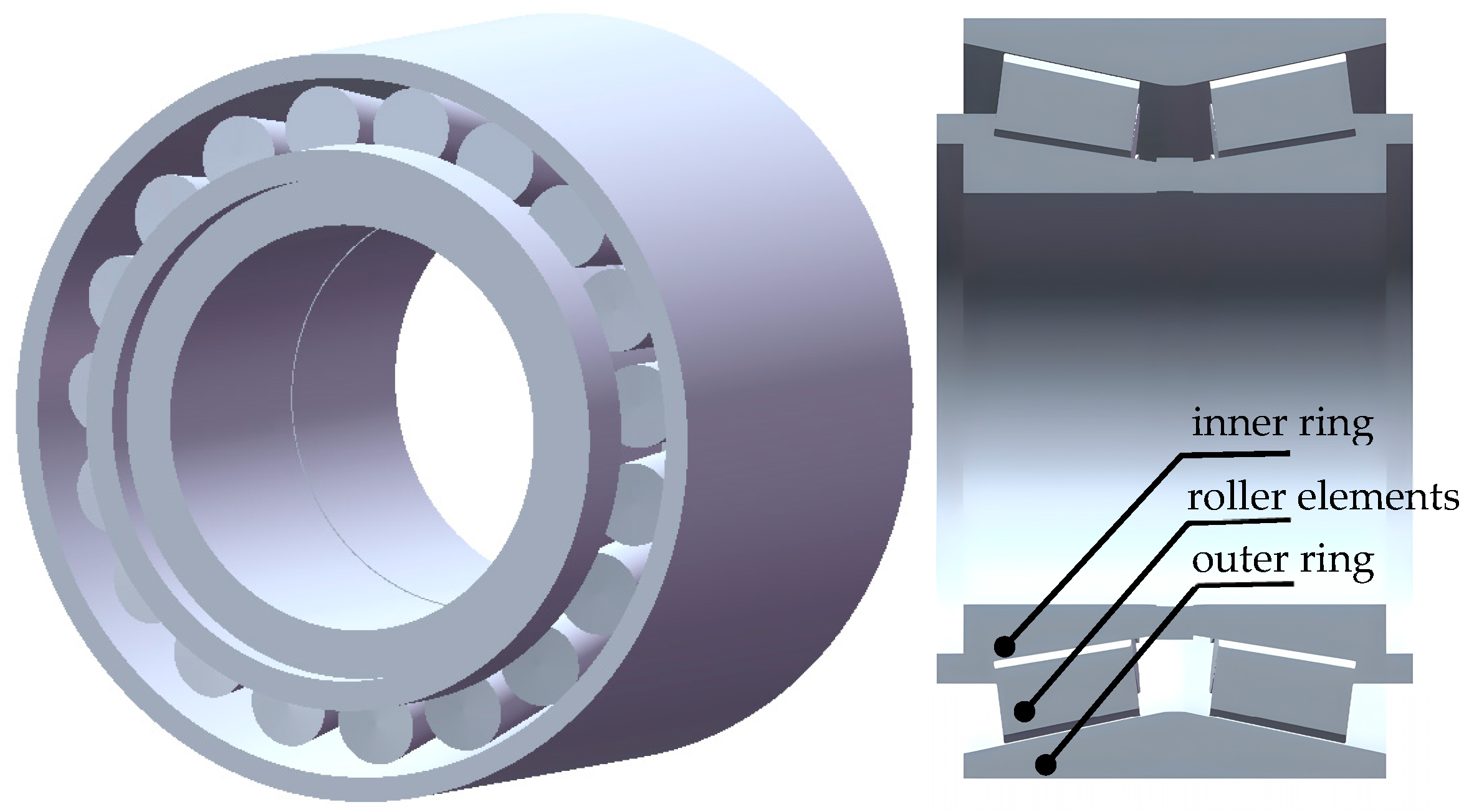
3.1. The Structural Feature of Double-Row Tapered Roller Bearings

The type 352226 axle box bearing used in high-speed trains consists of an integrated cage, a single-piece outer ring, two symmetrically arranged inner rings, one spacer, and 38 tapered rolling elements. The geometric parameters are shown in Table 1, and Figure 6 illustrates the structural diagram of the double-row tapered roller bearing.

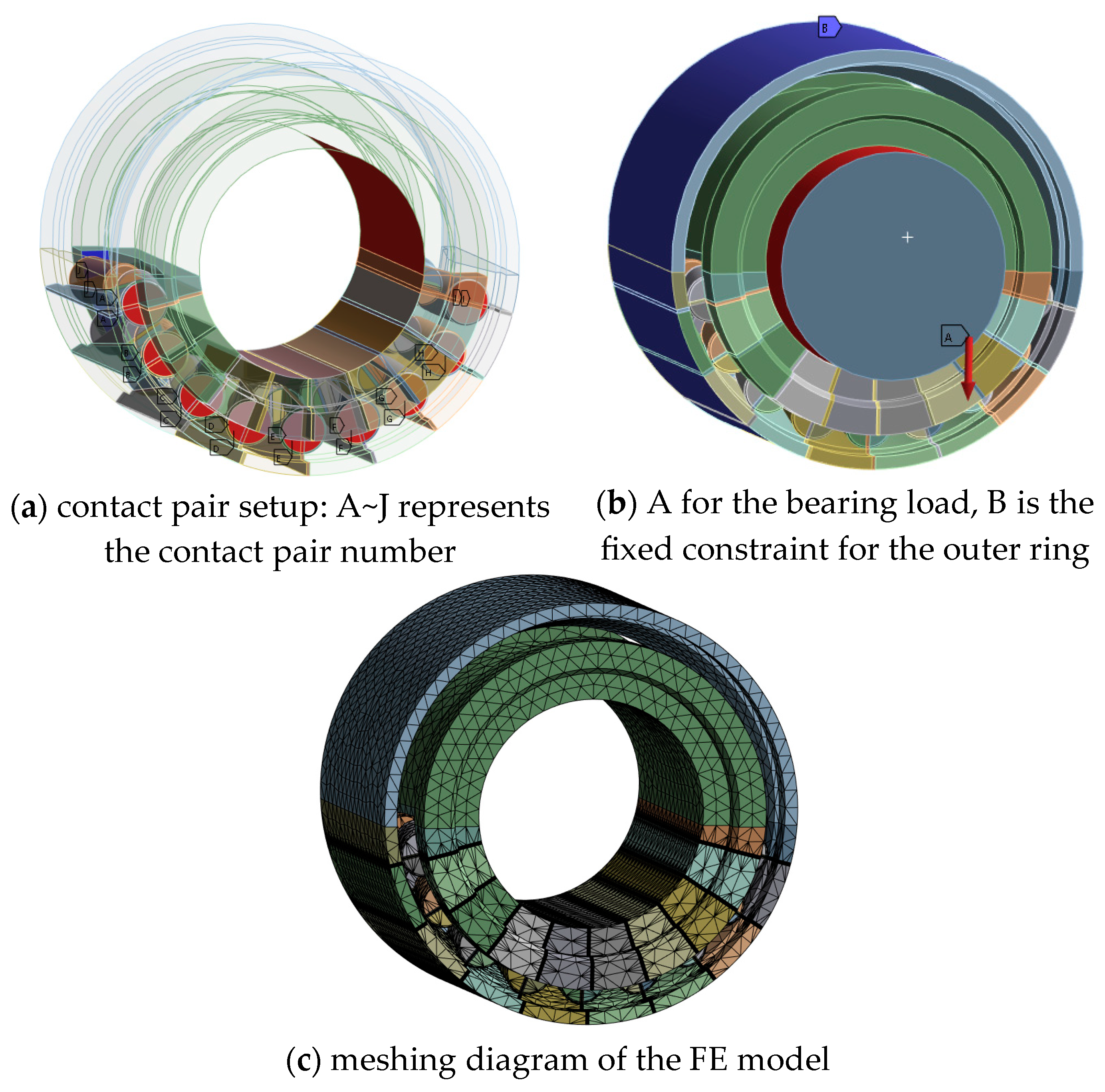
3.2. Mechanical Equivalent FE Modeling of the Bearing

Since the lower rolling elements bear the load, the upper rollers, which do not, are omitted. The chamfer at the end face is simplified while retaining the basic structure of the bearing. The contact regions between the rolling elements and the inner/outer raceways are segmented and modeled. A virtual shaft is constructed to simulate the actual load-bearing conditions by applying forces on its outer surface. The nonlinear contacts between the rollers and inner/outer raceways and the flange are solved iteratively.
An equivalent mechanical model with nine rolling elements is constructed, as shown in Figure 7, to meet the modeling accuracy and relatively high computational efficiency. A validation analysis of the equivalent model was performed to verify its correctness and effectiveness, as outlined below.

3.3. Model Verification by Grid Independence Analysis

Due to the large size of high-speed train axle box bearings, the mesh density in simulation analysis significantly impacts both the accuracy of calculation results and computational time. To ensure the correctness of the model’s computational results and the reliability of the analysis outcomes, a grid independence verification was performed on the meshing of the contact regions between the rolling elements and the inner/outer raceways.
The results of the grid independence analysis are shown in Figure 8. The stress results stabilized when the mesh size ranged from 1.5 mm to 2 mm, verifying the reliability of the model.

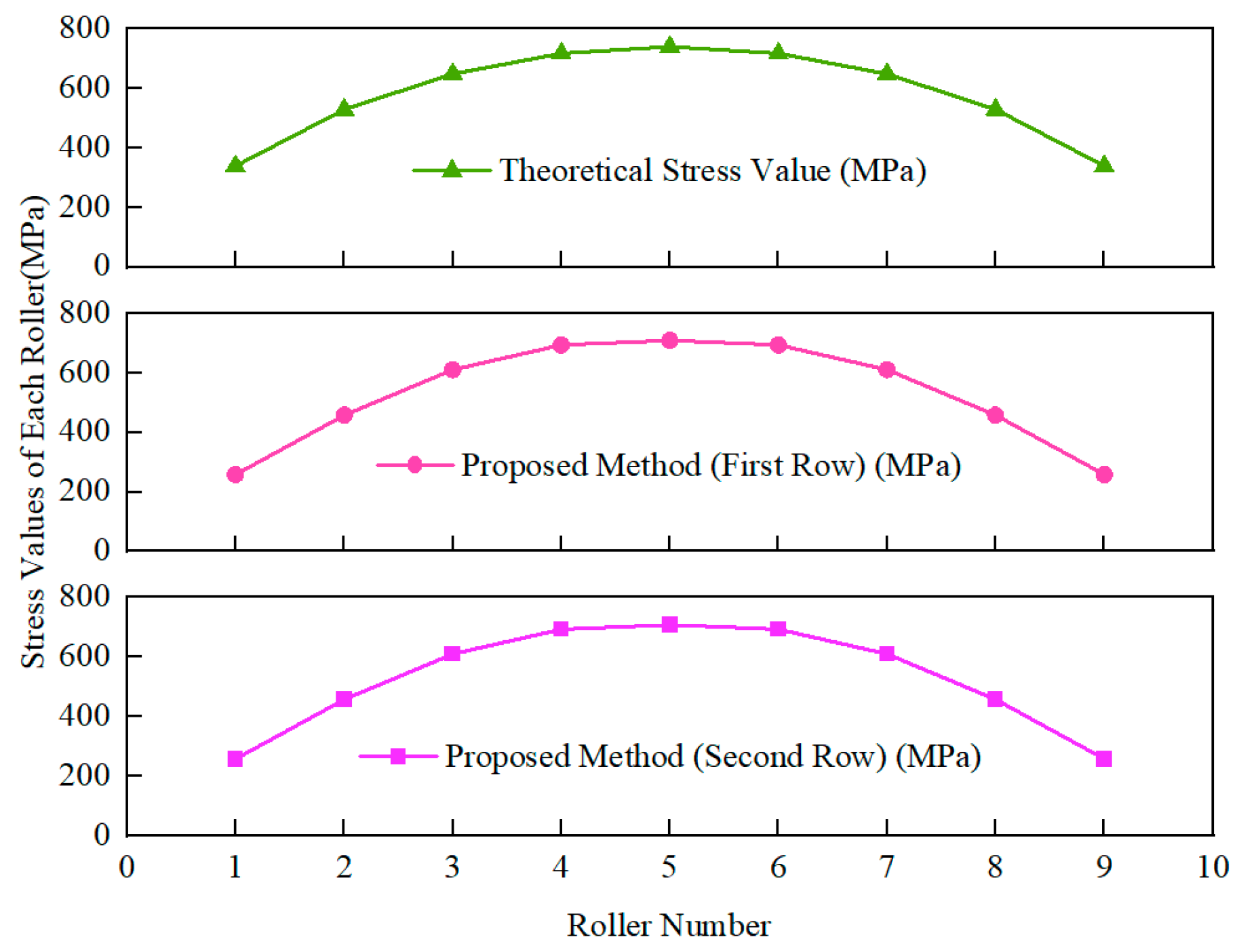
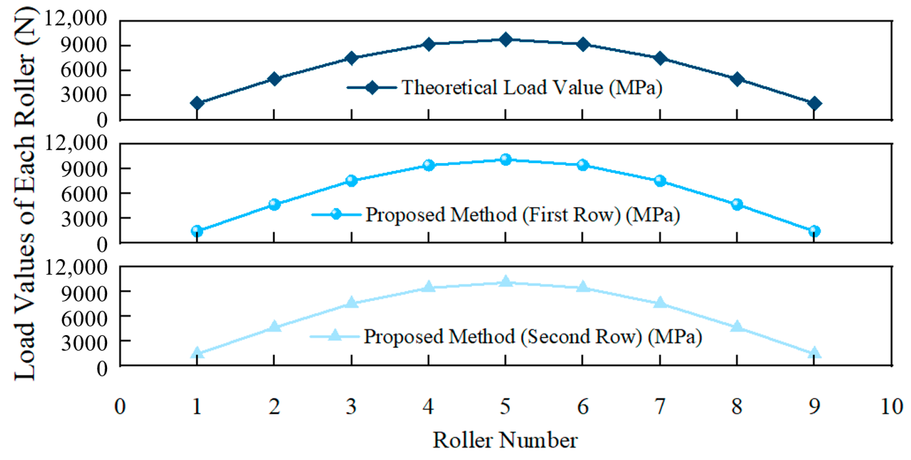
3.4. Case Analysis and Validation

After completing grid independence verifications, a series of simulation analyses were conducted, focusing primarily on the distribution of contact load and contact stress on the inner and outer raceways. The results are required to satisfy mesh independence in the calculations. The boundary conditions are that the outer ring is fixed, the virtual shaft on the inner ring exerts a load, and the rollers are set in nonlinear contact with the raceway. When a radial load of 90 KN is applied to the bearing, the simulation results were compared with theoretical solutions for validation to ensure the accuracy of the model. Figure 9 and Figure 10, respectively, show the simulation results of contact load and contact stress, which were compared with theoretical solutions.
As shown in Figure 9, the calculated contact stress of the rolling elements obtained using the proposed method is in basic agreement with the theoretical solution. This verifies the effectiveness of the proposed model in terms of contact stress and validates the overall reliability of the model. By comparing the finite element solution and theoretical solution shown in Figure 10, it can be concluded that the contact load of rolling elements obtained from the mechanical model proposed in this study are basically consistent with the theoretical solution with a maximum error less than 5%, which verifies the accuracy of the model proposed in the study.

3.5. The Construction of the Bearing Mechanical Model with Sensor-Embedded Slots

To study the mechanical characteristics of bearings with embedded sensor slots under actual loading conditions, sensor-embedded slots with different positions and depths were created on the bearing’s outer ring, and simulated load conditions were applied. In addition, the model considers the nonlinear contact behavior at the interfaces to ensure the accuracy and reliability of the computational results.
Figure 11 illustrates the circumferential positions of the embedded slots on the out ring. Specifically, α 1 = 33 ° for slot 2, while α 2 = 90 ° for slot 1. Figure 12 shows the dimensions of the embedded slots, and Figure 13 provides a sectional view of the embedded slot with primary dimensions.

4. Embedded Slot Bearing Mechanics and Fatigue Life Analysis

To study the mechanical characteristics of the contact region under practical load conditions in bearings with sensor-embedded slots, the research examined the stress distribution in the embedded slot region and evaluated the fatigue life based on the rated life standard. Groove depths and groove distances are set as influencing parameters to investigate the structural strength and fatigue failure mechanism of the embedded groove in intelligent sensor-integrated bearing under rolling contact conditions.

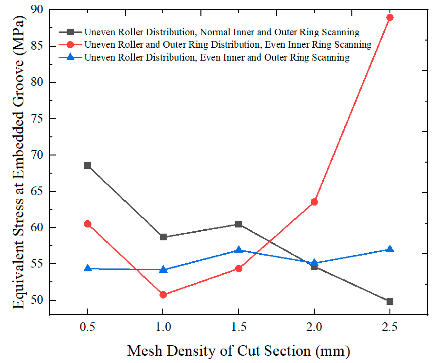
4.1. Mesh Independence Verification for Embedded Slot Bearing

A grid independence analysis was performed on the embedded slot bearing to align with practical conditions. A virtual mandrel was added to the inner ring of the bearing to simulate the shaft of a railway locomotive axle box bearing. Taking the axle box bearing with a 17-ton axle load as an example, three types of mesh division—standard sweeping, non-uniform sweeping, and uniform sweeping—were applied to the sliced sections of the inner and outer raceways and rolling elements. The convergence of the equivalent stresses at the embedded slots was analyzed for mesh densities of 2.5, 2, 1.5, 1, and 0.5 mm, respectively. Figure 14 shows the stress cloud of the embedded slot under non-uniformly swept rolling body and uniformly swept inner and outer raceway conditions. Figure 15 shows the deformation cloud diagram of the embedded slots. Figure 16 presents the mesh independence analysis diagram of the embedded slots.
It can be observed from Figure 16 that when the rolling body slice adopts non-uniform sweeping and the inner and outer raceway slices adopt uniform sweeping, the stress at the sensor-embedded slot stabilizes at approximately 55 MPa. Therefore, in order to ensure computational accuracy while maintaining consistency, a meshing unit size of 2.5 mm was adopted in the simulation.

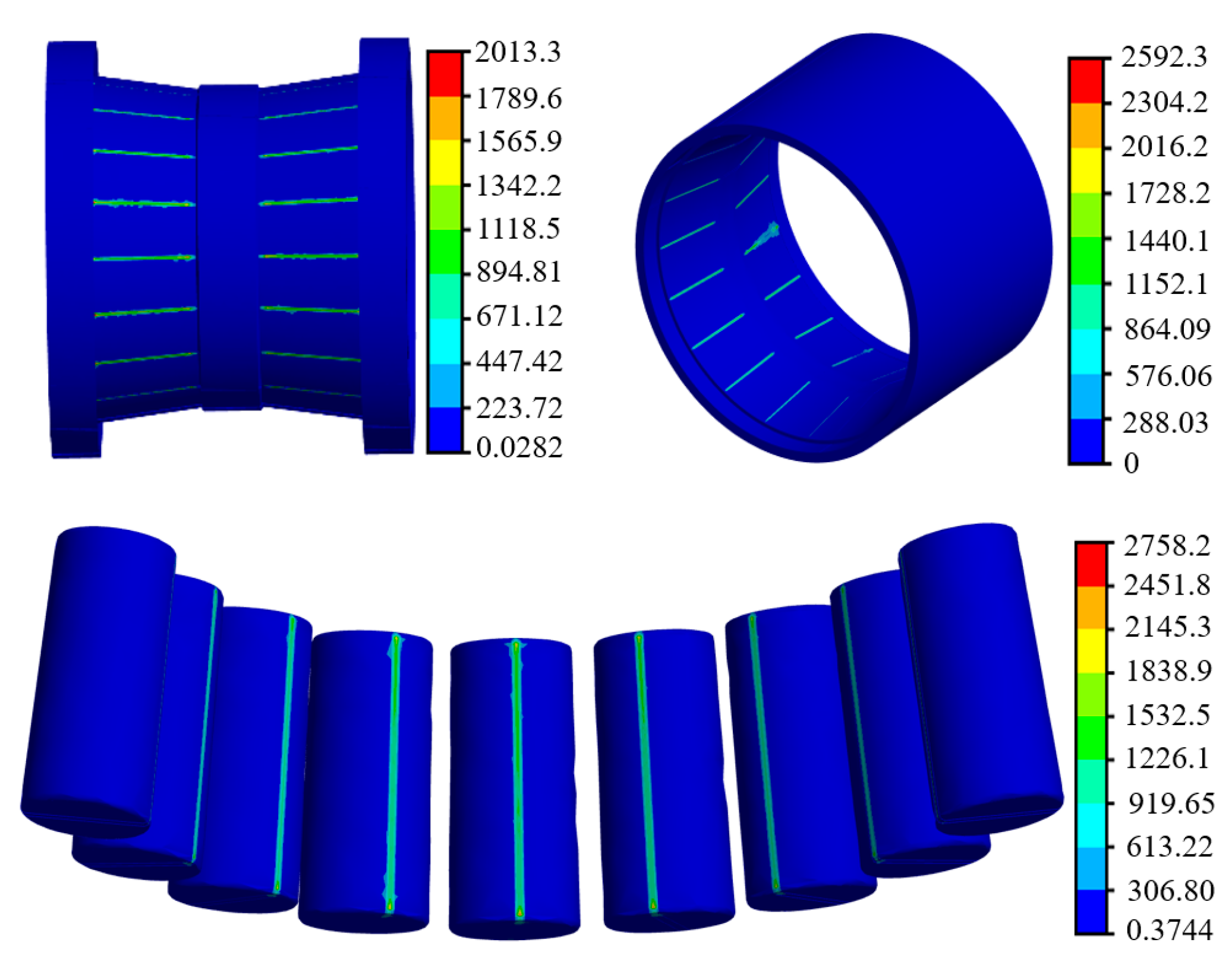
4.2. A Stress Analysis of Heterogeneous Ring Bearing Under Actual Load Conditions

According to the ISO [30] standardized method, the equivalent dynamic load for rolling bearings is the following:
P = X F r + Y F a ,
where X and Y are coefficients as listed in Table 2, and e = 1.5 tan α .
Under various actual working conditions [31], the maximum axial and radial loads were substituted into Equation (16) to analyze the equivalent dynamic load on the bearing. The maximum stress of the slot was extracted to analyze the influence of different slot depths and positions on the structural strength. As shown in Figure 17, the stress distribution within the embedded slots under varying dimensions was obtained. The stress clouds for the sensor-embedded slot and each bearing component are shown in Figure 18 and Figure 19, respectively.
According to the law of distortion energy density, distortion energy density is the primary factor leading to fatigue failure. Based on the strain energy density theory and the von-mises stress criterion, the permissible stress for the inner and outer raceway material is 550 MPa. Considering a safety factor of 2, the permissible stress is 275 Mpa.
In summary, when the axial distance between the groove and the end face is 25 mm and the groove depth is 5 mm, the maximum stress in the embedded groove is less than 275 MPa. When the axial offset distance of the groove is 30 mm with a groove depth of 5–6 mm, the maximum stress in the embedded groove also remains below 275 MPa, satisfying the stress strength requirements. However, other cases do not meet the requirements.

4.3. An Analysis of the Effect of Sensor-Embedded Slots on Fatigue Life

The influence of the offset distance of the embedded groove from the end face and the depth of the groove (as shown in Figure 17) on the life characteristics of the bearing was analyzed. Under normal operating and maintenance conditions for railway vehicle axle box bearings, with an inspection interval of 165 × 104 km, and at a 90% reliability level, the basic rated life of the axle box bearing is L 10 s > 360 × 104 km (calculated using an average wheel diameter of 885 mm. Therefore, to ensure consistency with the basic rated life of the axle box bearing, a load of 990 kN was applied. According to Section 2.3, the Hertzian contact cycles at the outer-ring groove center under this load are 8.21 × 10⁶. Consequently, the impact of the groove position and depth on the contact load and stress distribution of the bearing under a 990 kN load was analyzed.

4.3.1. The Influence of Embedded Slot Stress

Based on grid independence, the maximum life of the slot was extracted to analyze the influence of different slot depths and positions on the fatigue life. The relationship among the axial distance from the groove to the end face, groove depth, and maximum stress is illustrated in Figure 20. The analysis of the stress distribution of the grooves with different depths shows that the depth of the grooves has a great influence on the stress distribution. Increasing the groove depth noticeably raises the peak stress values in localized regions, thereby heightening the risk of fatigue damage. In addition, the peak stress in the localized region of the embedded slot increases as the offset distance of the slot from the end face becomes larger.

4.3.2. The Influence of Embedded Slot Fatigue Life

Based on the stress distribution of the embedded slot and the fatigue life model described in Section 2.3, the influence of groove depth and the offset distance on the fatigue life was analyzed, as shown in Figure 21. The results indicate that excessive groove depth not only increases the stress in the embedded grooves but also reduces the fatigue life. Analysis demonstrates that under a rated load of 990 kN, the fatigue life of the bearing with embedded grooves should not fall below 8.21 × 10⁶ cycles, highlighting a design inadequacy in the embedded groove configuration.
From the curves in Figure 21, it is determined that when the offset distance is 20 mm and the groove depth is 7–10 mm, or when the offset distance is 25 mm and the groove depth is 8–10 mm, or when the offset distance is 30 mm and the groove depth is within 10 mm, the bearing life is within acceptable limits.
To illustrate the evolution patterns of stress and fatigue life with respect to embedded groove depth and the offset distance from the groove to the outer-ring end face, a comprehensive analysis of the results from Section 4.2 and Section 4.3 is presented in Figure 22. The relationships among groove depth, offset distance, stress, and life were obtained. When the offset distance is 20 mm and the depth is 5–6 mm; or when the offset distance is 25 mm and the depth is 5–7 mm; or when the offset distance is 30 mm and the depth is 5–9 mm, the embedded slot life satisfies the usage requirements (i.e., the green regions in Figure 22). When the offset distance is 25 mm and the depth is 5 mm, or when the offset distance is 30 mm and the depth is 5–6 mm, the embedded groove life reaches the maximum allowable limit (i.e., the yellow regions in Figure 22).
In summary, to ensure that the structural strength and fatigue life of intelligent axle box bearings with sensor pre-embedded slots in the outer ring meet the requirements for use, the design parameters of the pre-embedded grooves for axle box bearings in railroad vehicles should be limited (i.e., the green area in Figure 22).

5. Conclusions

A bearing mechanical performance analysis model was established, incorporating virtual shaft simulation and rolling element contact. Based on bearing kinematic relationships and rated life theory, a theoretical model for the fatigue life of embedded slots in bearings was developed. The stress distribution at the groove with mesh refinement was obtained, and the effectiveness of the model was verified by comparing with theoretical values. Key conclusions are as follows:
(1)
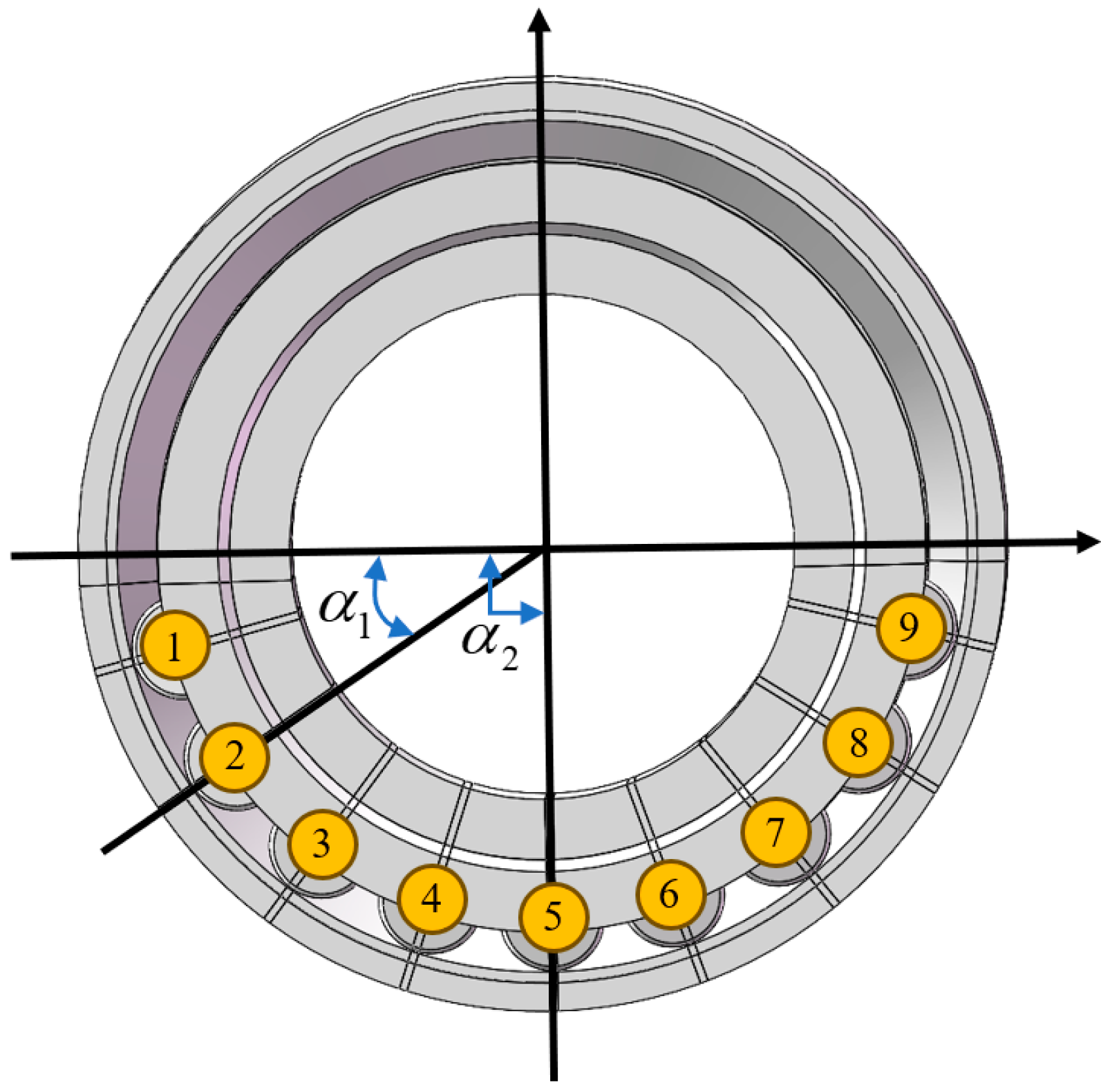
A mechanical equivalent an FE model with a virtual mandrel is established for double-row tapered roller bearings with sensor-embedded slots, which considers equivalent loads of axial and radial loads. Since the lower portion of rolling elements bear the load, the upper portion of rollers, which do not, are omitted. The chamfer at the end face is simplified while retaining the basic structure of the bearing. The contact regions between the rolling elements and the inner/outer raceways are segmented and modeled with mesh refinement.
(2)
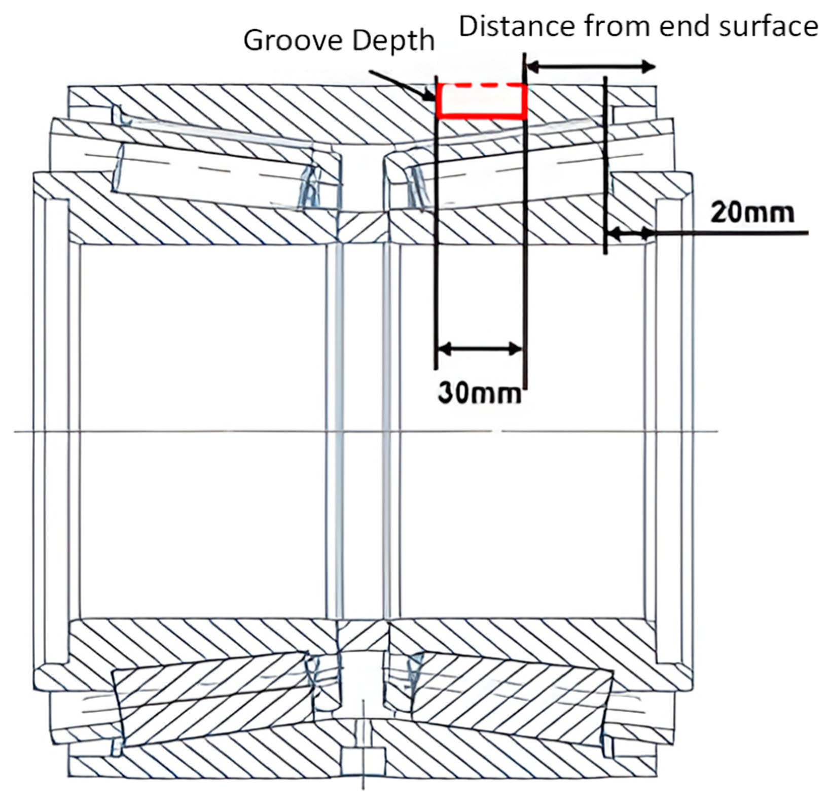
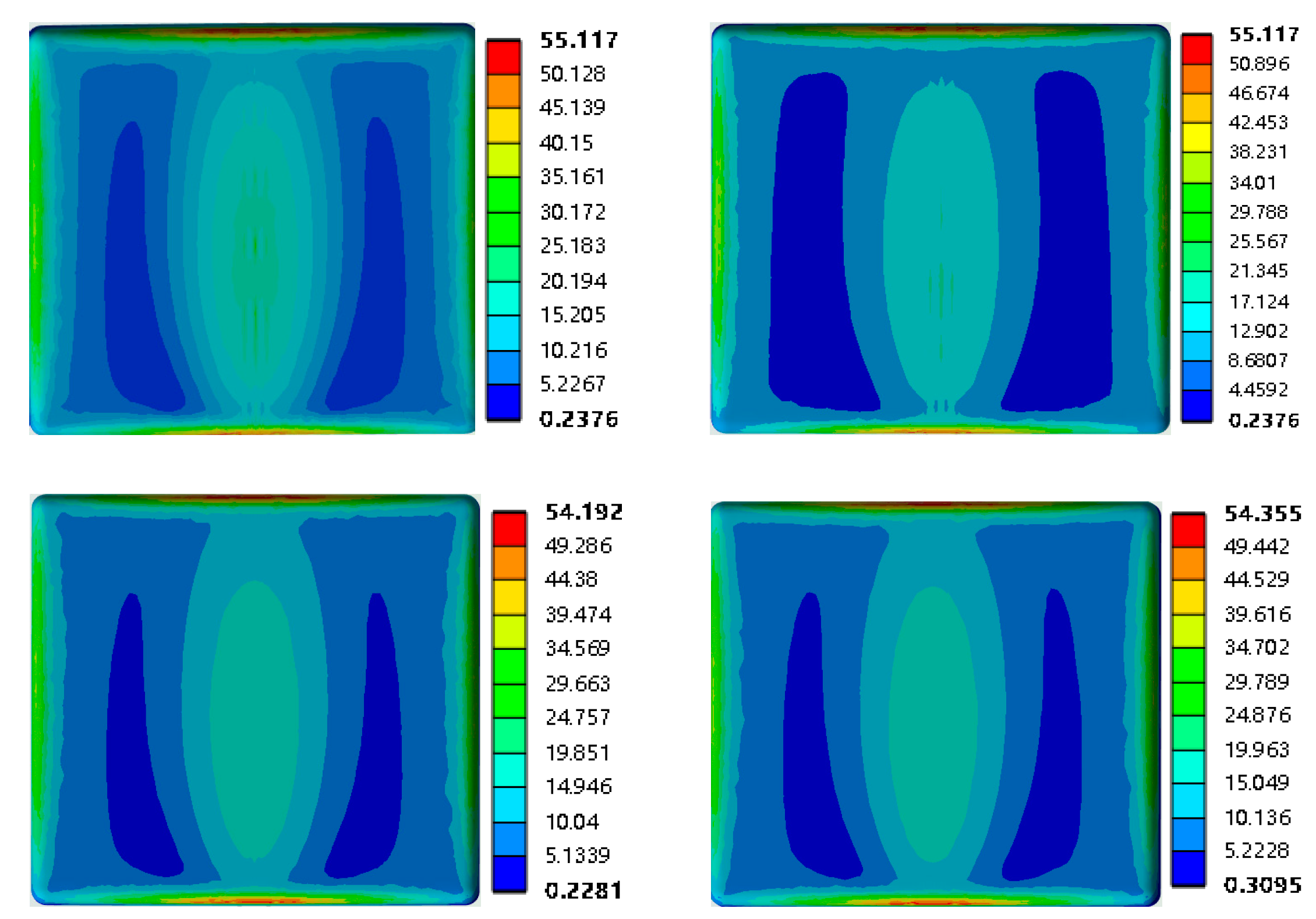
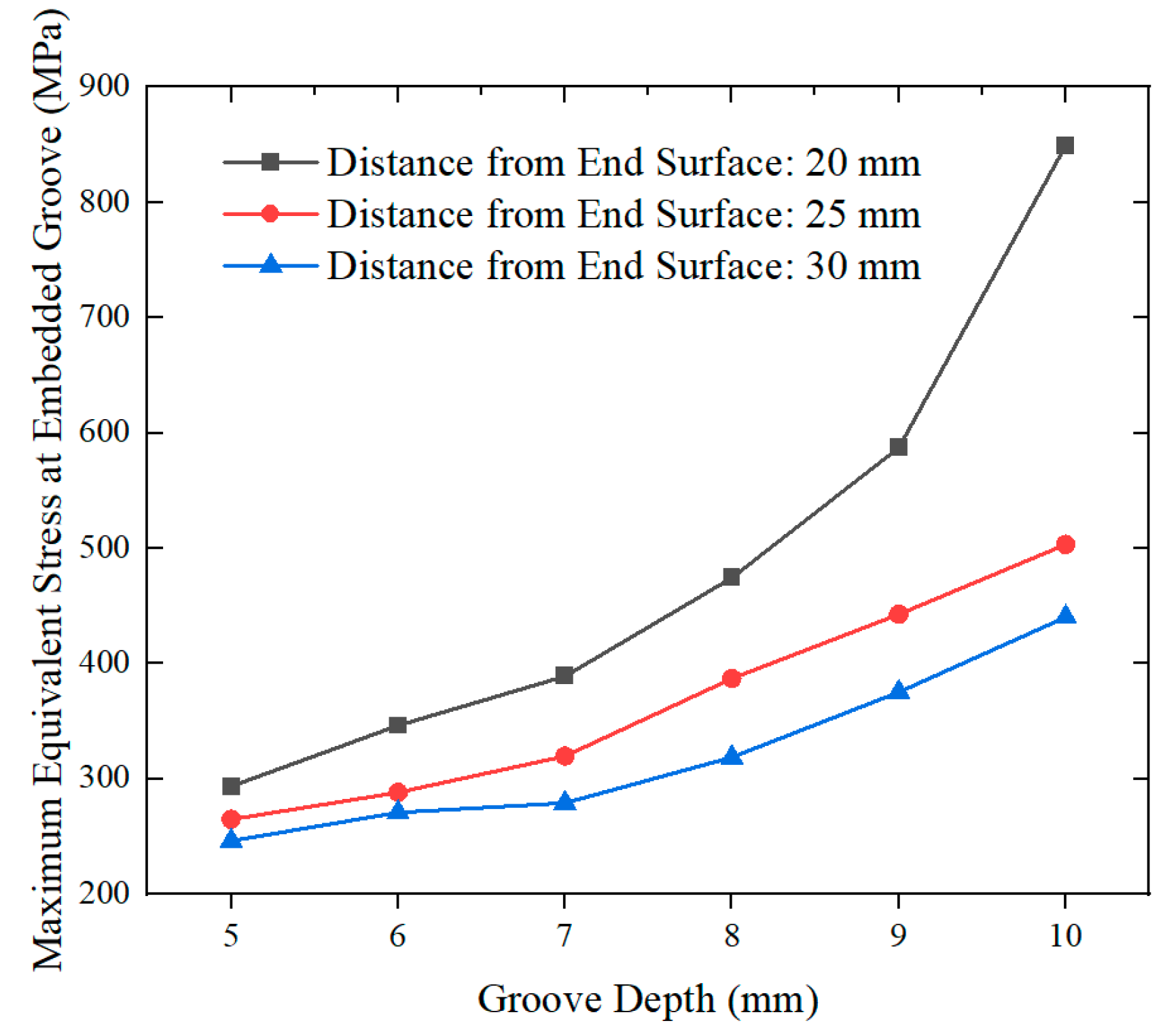
The position and depth of the slot significantly affect the stress distribution in local regions. Through simulation analysis and theoretical validation, it was determined that when the offset distance of the embedded slot from the end face is 30 mm, the depth of the groove should be within 5–9 mm. When the offset distance is 25 mm, the groove depth should be 5–7 mm. When the offset distance is 20 mm, the groove depth should be 5–6 mm. Localized stresses are small and evenly distributed, which can effectively increase the strength of the slots.
(3)
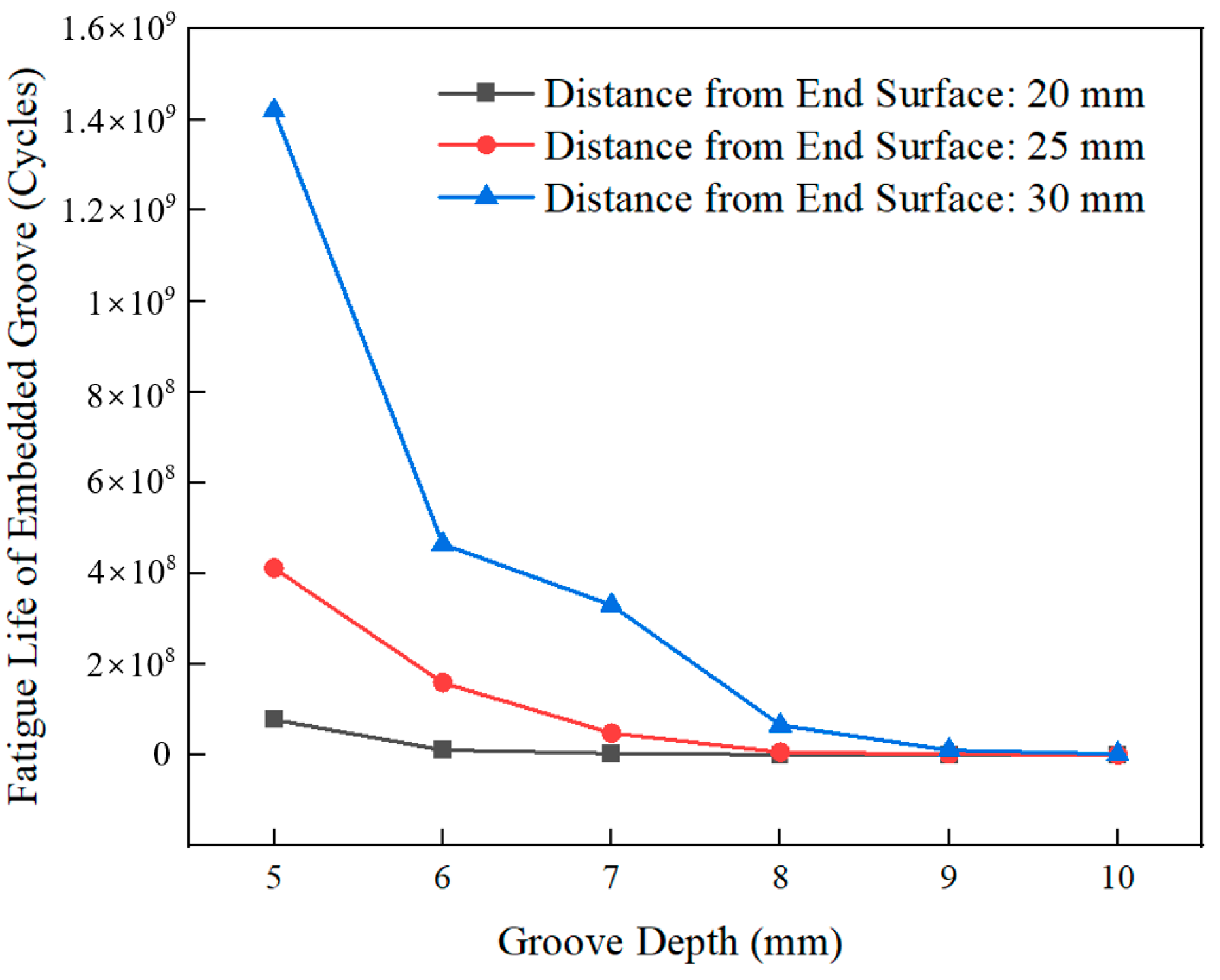
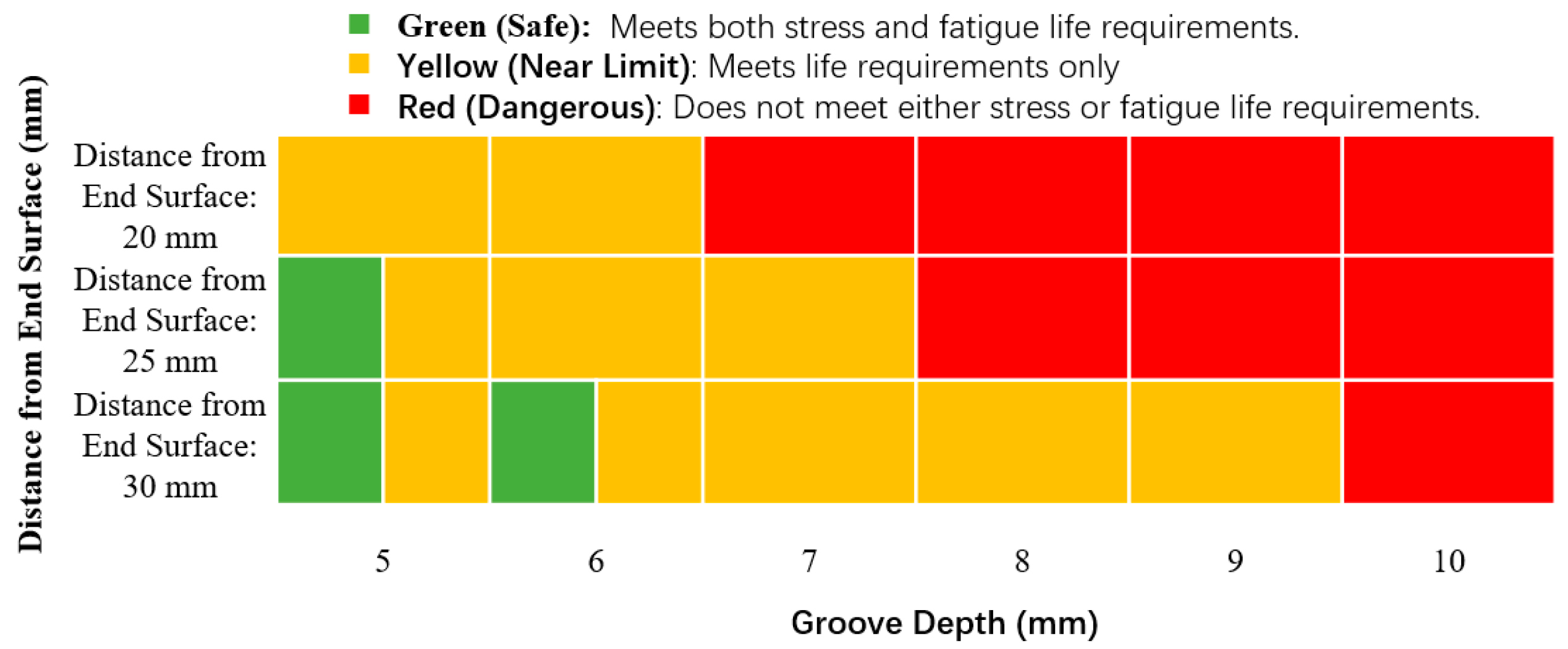
Through fatigue life analysis, it was identified that an excessive slot depth negatively affects bearing fatigue life, as demonstrated in the groove depth-limit diagram. For intelligent axle box bearings, when the offset distance of the slot is 20 mm, the depth should be 5–6 mm; when the offset distance is 25 mm, the depth should be 5–7 mm; and when the offset distance is 30 mm, the depth should be 5–9 mm, ensuring that the bearing life meets design requirements.
(4)
To ensure that the design of intelligent axle box bearings meets structural strength and fatigue life standards, it is recommended that the embedded grooves for intelligent sensors in railway vehicle axle boxes be designed carefully. The structural strength and fatigue life should be considered comprehensively.
(5)
In order to improve the applicability of the model and provide more effective life prediction, detailed experimental validation studies will be the suggest direction for the future study, and the model will be modified to further apply to other types of bearings, taking into account the effects of temperature, wear and lubrication factors, and will be further extended to the variable load conditions, so as to provide data support for the design and maintenance of rolling bearings.
The findings of this study offer practical implications for the design for the structural design of smart bearings with ring-embedded sensor slots. The structural strength is improved by determining the appropriate embedded groove location and depth, which provides valuable guidance for improving the high-reliability operation of the equipment.

Author Contributions

Conceptualization, L.H.; funding acquisition, L.W.; investigation, L.W. and C.H.; methodology, L.W., C.H. and H.T.; project administration, F.L. and H.T.; resources, L.H., F.L. and H.T.; supervision, L.H.; visualization, C.H. and F.L.; writing—original draft, C.H.; writing—review and editing, L.W. All authors have read and agreed to the published version of the manuscript.

Funding

This work was supported by the National Key R&D Program of China under Grant 2023YFB3406102, and supported by Hunan Provincial Natural Science Foundation of China under Grant 2025JJ60317 and 2025JJ80228.

Data Availability Statement

The data is included in the article.

Conflicts of Interest

The authors declare that they have no known competing financial interests or personal relationships that could have appeared to influence the work reported in this paper.

References

  1. Li, Z.; Wang, Q.S.; Wang, R.H.; Qin, B. Dynamic characteristics analysis of double row angular contact ball bearings with different bearing configurations. J. Mech. Eng. 2025, 65, 220–231. [Google Scholar]
  2. Lei, C.L.; Xue, W.; Fan, G.F.; Wang, Y.; Wang, F.; Li, J.F. Dynamic modeling of angular contact ball bearings considering composite defects in inner and outer rings. J. Vib. Shock 2024, 43, 275–283. [Google Scholar] [CrossRef]
  3. Zhang, K.; Zhang, L.Q.; Wang, Z.; Gao, L.W. Nonlinear dynamic characteristics analysis of full ceramic angular contact ball bearing considering ball slip. J. Vib. Shock 2024, 43, 131–138+172. [Google Scholar] [CrossRef]
  4. Li, J.F.; Wen, B.; Tian, P.; Ma, S.J.; Yan, K. Analysis on contact state of four-point contact ball bearings for typical working conditions. Bearing 2023, 12, 26–31. [Google Scholar] [CrossRef]
  5. Tu, W.B.; Wang, J.M.; Yang, B.M.; Liang, J.; Luo, Y.; Zhang, G.Y. Analysis of contact characteristics of rolling bearings under load fluctuation. J. Vib. Shock 2023, 42, 227–235. [Google Scholar] [CrossRef]
  6. Lei, C.L.; Song, R.Z.; Fan, G.F.; Liu, K.; Xue, W.; Li, J.H. Vibration characteristics of angular contact ball bearing with local defect considering impact excitation. J. Aerosp. Power 2025, 40, 20230211. [Google Scholar] [CrossRef]
  7. Luo, Y.; Yang, B.M.; Tu, W.B. Dynamic modeling of the contact between cage and rolling element in rolling bearing and contact characteristics. J. Aerosp. Power 2022, 37, 2887–2895. [Google Scholar] [CrossRef]
  8. Chu, M.; Yang, L.C.; Wang, Z.W.; Jiang, Z.W.; Wang, Q.; Mo, J.L. Study on the effects of curve geometry parameters and braking conditions on the dynamic characteristics of train axle-box bearing. J. Mech. Eng. 2025, 61, 187–198. [Google Scholar]
  9. Li, Z.; Guan, X.L.; Zhong, R.; Wang, Q.S. Analysis of dynamic characteristics of angle contact bearings with combined loads. J. Mech. Eng. 2020, 56, 116–125. [Google Scholar] [CrossRef]
  10. Gu, J.G.; Zhang, Y.M.; Liu, H.Y. Influences of wear on dynamic characteristics of angular contact ball bearings. Meccanica 2019, 54, 945–965. [Google Scholar] [CrossRef]
  11. Liu, J.; Li, X.B.; Shi, Z.F. An investigation of contact characteristics of a roller bearing with a subsurface crack. Eng. Fail. Anal. 2020, 116, 104744. [Google Scholar] [CrossRef]
  12. Xu, H.Y.; Wang, P.F.; Ma, H.; Yang, Y.; Li, X.P.; Luo, Z.; Han, Q.K.; Wen, B.C. Dynamic behaviors and contact characteristics of ball bearings in a multi-supported rotor system under the effects of 3D clearance fit. Mech. Syst. Signal Proc. 2023, 196, 110334. [Google Scholar] [CrossRef]
  13. Tonazzi, D.; Komba, E.H.; Massi, F.; Le, J.G.; Coudert, J.B.; Maheo, Y.; Berthier, Y. Numerical analysis of contact stress and strain distributions for greased and ungreased high loaded oscillating bearings. Wear 2017, 376, 1164–1175. [Google Scholar] [CrossRef]
  14. Shah, D.B.; Patel, K.M.; Trivedi, R.D. Analyzing Hertzian contact stress developed in a double row spherical roller bearing and its effect on fatigue life. Ind. Lubr. Tribol. 2016, 68, 361–368. [Google Scholar] [CrossRef]
  15. Talbot, D.; Li, S.; Kahraman, A. Prediction of mechanical power loss of planet gear roller bearings under combined radial and moment loading. J. Mech. Des. 2013, 135, 121007. [Google Scholar] [CrossRef]
  16. Liu, J.; Tang, C.K.; Wu, H.; Xu, Z.D.; Wang, L.F. An analytical calculation method of the load distribution and stiffness of an angular contact ball bearing. Mech. Mach. Theory 2019, 142, 103597. [Google Scholar] [CrossRef]
  17. Guo, L.; Yu, Y.X.; Chen, Z.G.; Liu, Y.Q.; Gao, H.L. Study on dynamic characteristics of urban rail transit vehicle considering faulty axle-box bearings under variable speeds. Mech. Syst. Signal Proc. 2024, 206, 110849. [Google Scholar] [CrossRef]
  18. Wang, M.K.; Yan, K.; Tang, Q.; Guo, J.D.; Zhu, Y.S.; Hong, J. Dynamic modeling and properties analysis for ball bearing driven by structure flexible deformations. Tribol. Int. 2023, 179, 108163. [Google Scholar] [CrossRef]
  19. Yu, A.D.; Huang, H.Z.; Li, Y.F.; Yang, W.X.; Deng, Z.M. A modified nonlinear fatigue damage accumulation model for life prediction of rolling bearing under variable loading conditions. Fatigue Fract. Eng. Mater. Struct. 2022, 45, 852–864. [Google Scholar] [CrossRef]
  20. Paulson, N.R.; Evans, N.E.; Bomidi, J.A.R.; Sadeghi, F.; Evans, R.D.; Mistry, K.K. A finite element model for rolling contact fatigue of refurbished bearings. Tribol. Int. 2015, 85, 1–9. [Google Scholar] [CrossRef]
  21. Warda, B.; Chudzik, A. Effect of ring misalignment on the fatigue life of the radial cylindrical roller bearing. Int. J. Mech. Sci. 2016, 111, 1–11. [Google Scholar] [CrossRef]
  22. Cheng, H.C.; Li, X.H.; Ma, G.H.; Shi, X.F.; Yang, Z. Fatigue life and fatigue reliability mechanism of ball bearings. J. Mech. 2024, 40, 79–92. [Google Scholar] [CrossRef]
  23. Li, H.F.; Wei, J.L.; Li, S.H.; Liu, Y.Q.; Gu, X.H.; Liu, Z.C.; Yang, S.P. Fatigue life prediction of high-speed train bearings based on the generalized linear cumulative damage theory. Fatigue Fract. Eng. Mater. Struct. 2023, 46, 2112–2120. [Google Scholar] [CrossRef]
  24. Jin, J.W.; Kang, K.W.; Lee, S. Fatigue analysis for automotive wheel bearing flanges. Int. J. Precis. Eng. Man. 2023, 24, 621–628. [Google Scholar] [CrossRef]
  25. Yu, A.D.; Li, Y.F.; Huang, H.Z.; Tong, H.; Diao, Q. Probabilistic fatigue life prediction of bearings via the generalized polynomial chaos expansion. J. Mech. Sci. Technol. 2022, 36, 4885–4894. [Google Scholar] [CrossRef]
  26. Heng, X.; Wang, A.L.; Zhang, H.B.; Yin, Y.J. Research on the dynamic variation law of the discontinuous characteristics of the curvic coupling of aero-engine rotors under working conditions. Eng. Sci. Technol. Int. J. 2024, 59, 101870. [Google Scholar] [CrossRef]
  27. Cong, T.; Wang, J.R.; He, J.T.; Liu, Y.J.; Chen, Y.; Liu, F.L.; Li, L. Microstructure evolution and fatigue crack initiation life prediction of actual failed bearings under GRCF conditions. Eng. Fail. Anal. 2025, 169, 109148. [Google Scholar] [CrossRef]
  28. Jiang, Y.; Zhu, T.Y.; Deng, S. Combined analysis of stiffness and fatigue life of deep groove ball bearings under interference fits, preloads and tilting moments. J. Mech. Sci. Technol. 2023, 37, 539–553. [Google Scholar] [CrossRef]
  29. Zhou, X.W. Mechanical Characterization and Testing of Double Row Tapered Roller Bearings. Ph.D. Thesis, Dalian University of Technology, Dalian, China, 2021. [Google Scholar]
  30. ISO 281; Rolling Bearings—Dynamic Load Ratings and Rating Life. The International Organization for Standardization: Geneva, Switzerland, 2007.
  31. Pan, B.L.; Yang, X.K.; Zhao, F.W. Influence degree research of typical service conditions to fatigue damage of axle-box bearing for high-speed railway. Railw. Locomot. Car 2022, 42, 1–7. [Google Scholar] [CrossRef]
Figure 1. Forces acting on the double-row tapered roller bearing.
Machines 13 00358 g001
Figure 2. Forces acting on a rolling element: (a) forces on the longitudinal section; (b) forces on the transverse section.
Machines 13 00358 g002
Figure 3. A schematic diagram of line contact.
Machines 13 00358 g003
Figure 4. A schematic diagram of contact stress distribution.
Machines 13 00358 g004
Figure 5. A schematic diagram of the bearing movement relationship.
Machines 13 00358 g005
Figure 6. A structural diagram of a type 352226 axle box bearing.
Machines 13 00358 g006
Figure 7. An FE mechanical equivalent model of a double-row tapered roller bearing (the colors in the picture have no special meaning).
Machines 13 00358 g007
Figure 8. Grid independence verification diagram.
Machines 13 00358 g008
Figure 9. A contact stress comparison of simulated and theoretical solutions.
Machines 13 00358 g009
Figure 10. A contact load comparison of simulation and theoretical results.
Machines 13 00358 g010
Figure 11. A diagram of the roller number and embedded slot positions.
Machines 13 00358 g011
Figure 12. A schematic diagram of sensor-embedded groove dimensions.
Machines 13 00358 g012
Figure 13. A cross-sectional structure diagram of the sensor-embedded slot.
Machines 13 00358 g013
Figure 14. A stress cloud diagram of the 1# embedded slot.
Machines 13 00358 g014
Figure 15. A deformation cloud diagram of the 1# embedded slot.
Machines 13 00358 g015
Figure 16. Meshing independence analysis of the embedded slot.
Machines 13 00358 g016
Figure 17. Stress distribution diagram of the embedded groove.
Machines 13 00358 g017
Figure 18. Stress cloud diagram of the embedded groove.
Machines 13 00358 g018
Figure 19. Stress cloud diagram of the bearing components.
Machines 13 00358 g019
Figure 20. The relationship between offset distance, embedded groove depth, and maximum stress.
Machines 13 00358 g020
Figure 21. The relationship between groove depth and embedded groove life.
Machines 13 00358 g021
Figure 22. A diagram showing the influence of embedded groove depth and offset distance on stress and fatigue life.
Machines 13 00358 g022
Table 1. Structural parameters of the bearing.
ParameterSymbolValue
Outer diameter D 240 mm
Inner diameter d 130 mm
Number of rolling elements z 38
Effective contact length L 52.04 mm
Outer contact angle α o 10.00°
Inner contact angle α i 7.57°
Half taper angle β 1.215°
Small-end diameter of roller d w 24.46 mm
Large-end diameter of roller p w 26.67 mm
Table 2. The values of X and Y for axle box bearings.
Parameter X Y
F a F r e 1 0.45   cot α
1.5   tan α 0.67
F a F r > e 0.67 0.67   cot α
tan α 1
Disclaimer/Publisher’s Note: The statements, opinions and data contained in all publications are solely those of the individual author(s) and contributor(s) and not of MDPI and/or the editor(s). MDPI and/or the editor(s) disclaim responsibility for any injury to people or property resulting from any ideas, methods, instructions or products referred to in the content.

