Abstract
To solve the low frequency vibration problem faced by heavy truck drivers, a positive real network inertial suspension structure combined with a skyhook inertial control strategy is adopted. This integrated approach effectively reduces low-frequency vibrations at the seat and human body levels. Specifically, this research aims to mitigate the acceleration experienced on the seat surface within the low-frequency range. Firstly, a human–seat dynamics model is established. Subsequently, based on the principles of network synthesis, the derivation of transfer functions for both first- and second-order systems is discussed, and the network parameters are also optimized. This paper further compares the optimization outcomes of first- and second-order skyhook seat inertial suspensions. An adaptive fuzzy sliding-mode controller (AFSMC) has been developed for an electromechanical inerter, ensuring it closely tracks optimal control performance. The findings demonstrate that the new suspension system achieves a 29.9% reduction in the root-mean-square value of seat surface acceleration and a 43.1% decrease in the road-bump peak acceleration compared to a conventional suspension system. The results show that the inertial suspension with skyhook inertial control is highly effective in completely suppressing seat surface acceleration within the low-frequency domain.
1. Introduction
Rough road conditions can generate low-frequency vibrations that may lead to various adverse health effects on the human body, including fatigue, back pain, motion sickness, and neurological disorders [1,2]. Zuska et al. conducted a review of anthropodynamic dummies that represent sitting human bodies, which are used for analyzing vibration comfort in motor vehicles [3,4,5], as vibrations can seriously affect the physical health of heavy truck drivers. Considering these findings, it is crucial to focus on research aimed at diminishing vibration transfer in automotive seat suspension systems [6]. Given the harsh environment experienced by heavy vehicle drivers, researchers have introduced suspension systems into car seats. Zhang et al. [7] studied scissor seat suspension. The effect of active seat suspension can be achieved by using seat-integrated suspension on heavy-duty vehicles [8]. Based on the research on active seat suspension control system models, it can be said that a more in-depth understanding of these exists [9]. Zhao [10] introduced a seat suspension system, often metaphorically referred to as the fifth suspension of the cab, into the overall model of seat suspension, and proposed a 4-DOF coupled driver–cab system model. Song [11,12] introduced a vibration isolation system that features a two-degrees-of-freedom design, incorporating a geometrically nonlinear inerter component. The active driving force of a rotating motor is applied to realize variable damping seat suspension [13]. In summary, heavy-duty vehicle seat suspensions generally add dampers into the suspension system to eliminate vibration. At present, the low-frequency vibration problem is solved by considering the seat suspension model [14,15], the introduction of motors, and new suspension systems [16,17,18]. Nevertheless, the existing research has not yet adequately addressed the question of whether optimization of low-frequency seat vibrations can be achieved by integrating an inerter into the seat suspension system.
At present, seat suspension systems of heavy-duty automobiles are developing with intelligence, comfort, and energy savings in mind. Air Suspension and semi-active suspension systems are the most common technologies at present, such as Sidem’s Air Suspension Seats series, Isringhausen’s RS series, and so on. Driver comfort can now be further enhanced by incorporating inertial containers into heavy-duty vehicle seat suspension systems. Originally proposed by Smith [19,20], an inerter functions similarly to a capacitive component within an electrical circuit. The electromechanical analogy theory is further refined. Compared to shock absorbers that use only springs, this shock absorber broadens the scope of mechanical implementations for complex impedances, and has successfully been applied across various sectors, including in vehicle suspension [21,22,23], aircraft landing gear systems [24,25,26], train suspension [27,28,29,30], and in building vibration control [31,32]. Liu et al. [33] summarized inerter-based vibration isolators in detail.
In current suspension research, relevant scholars are focused on employing novel technologies to enhance the safety and comfort of ground vehicles [34,35,36,37]. The semi-active control system is favored for its superior performance in comparison to passive control systems, coupled with lower energy consumption than that of active control systems. Ding et al. [38] proposed an improved control strategy for electromagnetic suspension skyhook inertia control. Wang et al. [39] discussed the application of neural network sliding-mode control in vehicles.
The majority of research efforts have focused on developing devices and control algorithms for inertial suspension systems without complex combinations. The real network approach could significantly expand the scope of research on seat suspension systems [40]. As a characteristic of the inerter, low-frequency vibrations in the seat are significantly reduced, while skyhook inertial control has also proven effective in the low-frequency range. Research has shown that skyhook control can substantially improve acceleration of the sprung mass by the vehicle body, and can clearly optimize vibrations in the low-frequency spectrum. Therefore, skyhook control can be effectively applied to the seats of heavy vehicles to enhance driver comfort.
At present, research on integrating the positive real network of inertial suspension systems with skyhook inertial control to optimize the low-frequency vibration issues of heavy vehicles is relatively scarce. To address these challenges, this paper integrates skyhook inertial suspension with a positive real network, examining the impact of passive network order variations on suspension dynamics. Concurrently, the paper acknowledges the increasing technical complexity seen in seat suspension design, and the heightened challenge of developing precise models. The complex interactions between the positive real network and inerters in the skyhook suspension system are analyzed in detail. This study also delineates the constraint conditions necessary for the response index, ensuring a robust optimization framework. The research ideas and innovations of this paper are shown in Figure 1.
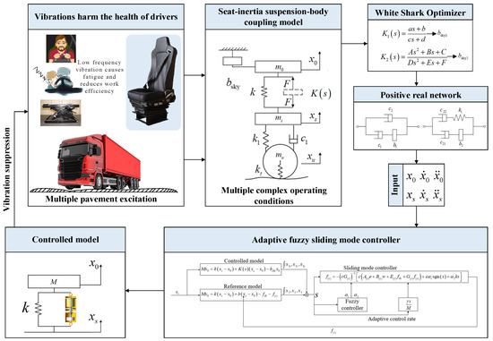
Figure 1.
Challenges and potential solutions.
The paper’s layout proceeds sequentially, as follows: First, the seat suspension dynamics model considering the ideal skyhook inerter is established. In the third part, the parameters of the skyhook inertial positive real network are optimized, consequently yielding the acquisition of an optimized mechanical network structure. The fourth section analyzes the dynamic characteristics of skyhook seat inertial suspension. In the fifth section, a controller is meticulously engineered, leveraging the optimal seat suspension model as its foundation, and its performance is rigorously simulated to ensure efficacy. The final section is the conclusion.
2. Seat Inertial Suspension Model
2.1. Heavy-Duty Vehicle Seat Inertial Suspension Model
The model of the seat is depicted in Figure 2, where and , respectively, represent driver mass and seat mass, and is the ideal skyhook inerter. Driver mass displacement, seat mass displacement and sprung mass displacement are denoted by , and , respectively. and represent the torso stiffness coefficient and torso damping coefficient. The system comprises two principal components: a passive component and a component featuring skyhook inertial control. The passive part has a shock absorbing spring, , and a positive real network structure, , and the skyhook inertia is based on the ideal skyhook inerter. In order to achieve optimal inertial control for the skyhook, a semi-active control device is incorporated. Figure 2 shows a model combining the positive real network and skyhook inertial control.
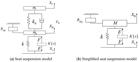
Figure 2.
Seat suspension model.
The equation for vertical motion is as follows:
In this context, represents the force transmitted through the mechanical network , while and are the acceleration of the human body and the seat, respectively.
The design of a system with multiple degrees of freedom, the semi-active control algorithm, is more complex, making its practical engineering implementation challenging. Therefore, the human–seat model in Figure 2a is simplified into a whole, as shown in Figure 2b, for a simpler controller design that is more easily applicable in practical applications. The simplified seat model is as follows:
with the formula: .
2.2. Passive Network Synthesis
We will introduce the optimization of the passive network of the mechanical system through the optimization algorithm to obtain the corresponding mechanical structure; the following is the specific content:
The systems referred to as are first-order positive real networks, denoted as , and second-order positive real networks, denoted as , respectively. Here is the Laplace variable. The expressions:
The sufficient conditions necessary for and to be positive real functions are as follows: , and for not all of to be 0.
The seat suspension parameters studied are presented in Table 1.

Table 1.
Seat suspension parameters.
3. Seat Suspension Optimization Design
3.1. Selection of Optimization Objectives
Here, Multi-Objective Particle Swarm Optimization (MOPSO) is adopted. Comfort is the primary objective of optimization, with suspension dynamic travel and seat surface amplitude transfer limits being considered in the optimization process. In this paper, the root-mean-square (RMS) value of seat surface acceleration is used to define the optimization target. The analysis prioritizes ride comfort, dynamic travel of the suspension, and the amplitude transfer of the seat surface. The article outlines the objective function for optimizing seat inertial suspension systems and formulates its expression, as follows:
where , and are RSM values of seat surface acceleration, maximum dynamic deflection, and seat surface amplitude transfer, respectively. , and are the RMS values for seat surface, maximum dynamic deflection, and seat surface amplitude transfer based on the optimization objective function, respectively. The SEAT index is the ratio between the RMS between the passenger and the seat rail. Among them, is divided into the weight of three performance indicators: weighted acceleration value, maximum dynamic deflection, and effective amplitude transfer of the seat. In this paper, considering that seat acceleration directly reflects the ride comfort of the vehicle and is the most important evaluation index, the weight coefficient of seat acceleration is selected as 0.5. The vibration transfer rate reflects the damping performance of the seat suspension, and the weight coefficient is 0.3. The dynamic travel of the seat suspension needs to be less than the dynamic travel of the seat suspension, so the weight coefficient is 0.2.
3.2. Constrained Optimization
Based on the formulation presented in Equation (3), the parameters slated for optimization are . Parameters of the constraint conditions are as follows:
where is not all 0. It is demonstrable that every first-order positive real impedance function, as depicted in Equation (3), can be embodied within a damped-spring inertial network comprising a maximum of three elements.
As in Equation (4), the parameters to be optimized are . Parameters of the constraint conditions are as follows:
where are not all 0. At the same time, the following conditions must be met:
Specific performance constraints are set within the framework of both first- and second-order skyhook inertial positive real networks, as detailed below:
where and are RSM values of seat surface acceleration, maximum dynamic deflection, and seat surface amplitude transfer, respectively. , and are the RMS values of seat surface acceleration, maximum dynamic deflection, and seat surface amplitude transfer, and are based on the optimization objective function.
3.3. Solution of Seat Suspension Structure Based on Passive Network Synthesis
During the optimization process, the pavement input is characterized by a Class C stochastic surface, which is simulated as moving at a velocity of 20 m/s. The road’s roughness coefficient, , is . After conducting several optimization iterations, the selected optimization parameters are as Table 2 shows.
Table 2.
Parameter optimization results.
The transfer function of and is converted into a mechanical structure composed of mechanical elements such as damper-spring inerter. The transfer function is:
Based on Equations (7) and (8), and previous studies in the literature [41], as long as the necessary regularity conditions are satisfied, the corresponding mechanical structure can be derived by applying Foster’s reactance theorem. The detailed mechanical network structure is shown in Figure 3, and the parameters of the seat inertial suspension system are listed in Table 3.
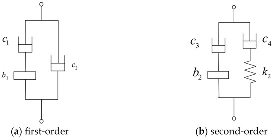
Figure 3.
Positive real network structure of seat inertial suspension.
Table 3.
Component parameters for seat inertial suspension.
4. Performance Analysis of the Network Seat Suspension
4.1. First-Order Skyhook Seat Inertial Suspension Systems
During the optimization process, the pavement input is characterized by a Class C stochastic surface, which is simulated as moving at a velocity of 20 m/s. The random pavement excitation input model adopted in this paper is as follows:
where is the vehicle speed, is the vertical input displacement, is the white noise with an average value of 0, and is the road roughness coefficient. In this paper, grade C pavement is selected, and the road roughness coefficient is .
Figure 4 illustrates the comparative analysis of seat surface acceleration and suspension working space across traditional suspension, skyhook suspension, first-order seat suspension, and first-order skyhook seat inertial suspension systems. Here, the traditional suspension of two-element structure with parallel spring and damper is selected as the comparison object. The spring value of the traditional suspension is 15 , and the damping value of the traditional suspension is 1.906 .
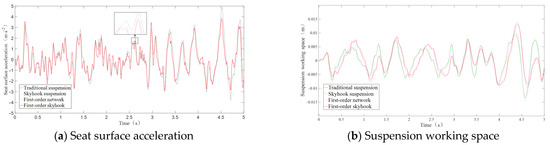
Figure 4.
Comparison of time domain.
As shown in Table 4 and Figure 4, the time-domain index analysis indicates that the proposed method outperforms the traditional suspension system. Specifically, the RMS values of the skyhook inertial seat surface acceleration and suspension workspace decreased by 3.5% and increased by 9.4%, respectively. The first-order network seat surface acceleration and suspension workspace RMS value decreased by 14.97% and increased by 5.66%, respectively. The RMS value of the acceleration at the seat surface was diminished by 17.06%. The RMS value of the suspension workspace shows significant degradation in both the skyhook inertial control and first-order network configurations, compared to traditional systems. The first-order skyhook seat inertial suspension demonstrates significant performance enhancement over the standard skyhook inertial suspension in time-domain evaluations. Figure 5 illustrates the power spectral density (PSD) of the seat surface acceleration.
Table 4.
Comparison of RMS values of first-order seat inertial suspension.
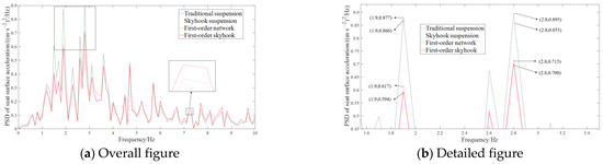
Figure 5.
PSD of first-order skyhook seat surface acceleration.
Convert the time domain acceleration signal to the frequency domain using Fourier transform:
where is the representation of the acceleration signal in the frequency domain, is the frequency (Hz), and is the imaginary number unit.
Calculate the power spectral density:
where is the sampling frequency and is the total number of sampling points of the signal. The sampling frequency is set to 1000, and the total sampling number is set to 10,000, as seen in Figure 5
As can also be seen in Figure 5, the natural frequencies of suspension are 1.9 Hz and 2.8 Hz. In contrast, the first-order skyhook seat inertial suspension system has a significantly lower natural frequency, with decreases of 32.3% and 21.7% at 1.9 Hz and 2.8 Hz. This indicates that the first-order skyhook seat inertial suspension system effectively mitigates vibrations in the low-frequency range on the seat surface.
Heavy vehicles need to travel long distances and have high speed requirements. As shown in Figure 6, as the speed of the heavy vehicle increases, as delineated in the comparative analysis, the RMS acceleration of the first-order skyhook inertial seat surface decreases, with further reductions compared to traditional suspension systems. When a Class C road becomes a Class B road, the optimization effect of the first-order skyhook inertial seat surface acceleration does not change. The suspension performance remains stable with increasing speed.
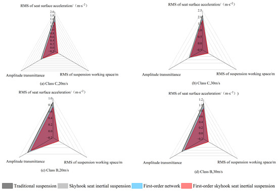
Figure 6.
Radar diagram of first-order skyhook seat inertial suspension performance under different road excitation conditions.
4.2. Second-Order Skyhook Seat Inertial Suspension
During the optimization process, the pavement input is characterized by a Class C stochastic surface, which is simulated as moving at a velocity of 20 m/s. The road’s roughness coefficient, , is , as in Equation (15). The time-domain performance is shown in Figure 7.
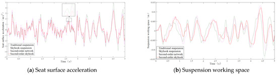
Figure 7.
Time domain diagram comparison.
With reference to Table 5 and Figure 7, it is observed that the skyhook inertial suspension seat surface acceleration has a 3.5% reduction, while the suspension workspace RMS value experiences a 9.4% increase compared to the traditional suspension system. The second-order network seat surface acceleration and suspension workspace RMS value decreased by 18.7% and increased by 5.66%, respectively. The seat surface acceleration of the second-order skyhook seat inertial suspension decreased by 27.98%. The second-order skyhook seat inertial suspension system significantly outperforms the standard skyhook inertial suspension in the time-domain assessment, achieving a 15.1% reduction in seat surface acceleration over its first-order counterpart. It also exhibits a marked enhancement in low-frequency vibration isolation performance.
Table 5.
Comparison of RMS values of second-order seat inertial suspension.
As can be seen from Figure 8 and Table 5, the natural frequencies of suspension occur at 1.9 Hz and 2.8 Hz. Compared to traditional suspension systems, the inherent frequency of the second-order skyhook seat inertial suspension is markedly reduced, with respective reductions of 31.2% and 34.5% at frequencies of 1.9 Hz and 2.8 Hz. This indicates that the second-order skyhook seat inertial suspension system significantly suppresses seat surface vibrations within the low-frequency range. Furthermore, the presence of an inerter significantly lowers the natural frequency of the suspension system. However, it is noteworthy that the seat surface acceleration of the first-order skyhook seat inertial suspension exhibits a degree of deterioration at mid to high frequencies [42]. The PSD of seat surface acceleration in the second-order skyhook seat inertial suspension does not deteriorate. Full spectrum optimization is achieved. The second-order skyhook seat inertial suspension system demonstrates superior performance compared to its first-order counterpart.
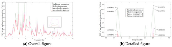
Figure 8.
PSD of second-order skyhook seat surface acceleration.
As depicted in Table 5 and Figure 9, the RMS value of the seat acceleration of second-order skyhook mount inertial suspension system increases with increases in vehicle speed, in comparison to traditional suspension. Notably, the optimization effect on seat surface acceleration is consistent when moving from a Class C to a Class B road surface. Furthermore, the suspension performance remains stable with increasing speed.
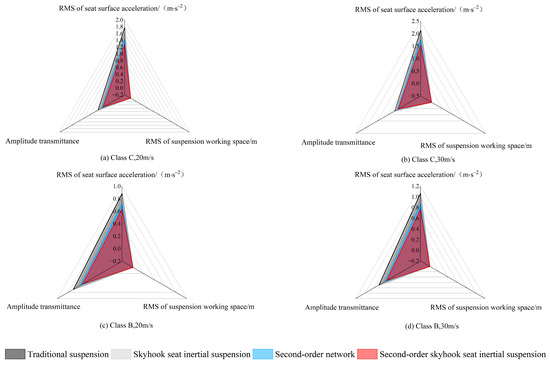
Figure 9.
Radar diagram of suspension performance under different road excitation conditions.
The RMS value of dynamic travel remains stable and does not exhibit a decline when comparing the performance of the first- and second-order networks. Furthermore, the RMS value of the second-order skyhook seat inertial suspension is markedly lower than that of the first-order system. Considering the frequency domain, the second-order skyhook seat inertial suspension decreases the frequency of suspension at 0–10 Hz, and the first-order skyhook seat inertial suspension exhibits a degree of degradation in performance within the mid-to-high frequency spectrum. Therefore, the second-order skyhook seat inertial suspension is used as a reference model.
5. Design of Second-Order Skyhook Seat Inertial Suspension Control System
Although the second-order skyhook seat inertial suspension has many components and is difficult to engineer, it was selected as a reference model because of its excellent performance. AFSMC was employed to ensure that the dynamic deviation between the actual and reference models converges to zero during the sliding phase. The results show that the actual model performs similarly to the reference model under sliding-mode control, leading to a superior frequency response for seat quality within the lower frequency spectrum.
5.1. Fuzzy Sliding-Mode Controller Modeling and Approach Rate Design
The optimized second-order skyhook seat inertial suspension serves as the reference model for performance benchmarking. Simultaneously, the control model consists of a controllable seat inertial suspension system, integrated with an electromechanical inerter. An electromechanical inerter is effectively modeled as a controllable force element that operates in conjunction with an inerter, as illustrated in Figure 10. The rotating motor is labeled ‘1’, and the ball screw inerter is labeled ‘2’. The kinetic equations of the second-order skyhook seat inertial suspension model are as follows:
where is the disturbance generated in the process of seat–human model simplification, , and refers to the disturbance generated externally during the actual work of the seat. Select , , , then:
with the formula: ; ; ; ; ; ; ; .
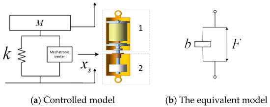
Figure 10.
Controlled and equivalent models.
The tracking-deviation system is defined as:
where is the integral of the displacement deviation; is the displacement deviation; and is the velocity deviation. By differentiating Equation (24), the system deviation dynamic equation is as follows:
formula: ; ; ; ; ; is the inertial coefficient of the skyhook inerter.
For the selection of the sliding surface:
where is the undetermined parameter, and the polynomial should be the Hurwitz polynomial. To satisfy the above conditions, take , and either .
The derivation of the sliding-mode surface Equation (27) is obtained:
Designed as:
It can be obtained by Equations (27) and (28):
Substituting , and vector into Equation (29), respectively, yields:
is the Lyapunov function, derived by:
To obtain the traditional sliding-mode control law, one must first determine the perturbation of the model when simplifying the process as well as external interferences . However, in the actual system, this disturbance is often uncertain, and the exact value cannot be given, and this part cannot be ignored. To avoid affecting the system’s control input , adaptive processing of is necessary. A reasonable adaptive law is designed to estimate online and reduce its influence on system performance. When the adaptive control method is used to estimate , the control law can be obtained according to Equations (27) and (30):
Define the Lyapunov function as:
In the equation, is assumed; that is, yields , , so
Adaptive law:
where is the estimated value of , , and is the undetermined parameter, .
In actual controls, due to the influence of driver weight change, system lag deviation, and other factors, it is impossible to have an ideal sliding mode. In order to prevent the control signal from being too large due to infinite increases of , it is necessary to make change within a certain range . Therefore, this paper introduces a mapping adaptive algorithm to modify Equation (36).
Here, the numbers and correspond to the peak and nadir values of , respectively. In this paper, 10% of the human body mass change is selected as the value of and ; that is, and . When exceeds the maximum value, if there is a tendency to continue increasing at this time, remains unchanged; that is, . On the other hand, when exceeds the minimum value, there is a trend of continued reduction at this time, so that remains unchanged; that is, .
The system’s inerter causes a dynamic response that leads to the continuous intersection of moving points with the sliding-mode surface, inducing the system’s buffeting phenomenon. The sliding-mode control system’s dynamic performance can be significantly enhanced by carefully selecting the approach rate in its design.
Equation (28) indicates that a larger selection of increases the distance across the sliding-mode surface, intensifying system buffeting and potentially destabilizing it. While choosing a smaller can reduce buffeting, it also slows the system’s approach speed. To mitigate buffeting effects and maintain a suitable approach speed, it is essential to incrementally adjust while concurrently reducing . However, as Equation (31) shows, when the trajectory point is far from the sliding-mode surface, an excessively large can lead to a proportionate increase in the semi-active damping force. Since the output force range of the semi-active inerter is limited, it is crucial not to select an excessively large . Therefore:
In this equation, is the output value of fuzzy control, and the input and output membership functions are designed with a triangular overlapping symmetric distribution. The distances between the moving-point and the sliding-mode surface serves as the fuzzy input variable. Details for the fuzzy control rules are provided in Table 6.
Table 6.
Fuzzy control rules.
In the defuzzification process, the centroid method determines the precise control quantity. The corresponding output calculation equation is presented below:
where and are, respectively, the control gains after defuzzification. and are, respectively, the membership degree functions of each fuzzy set, where , is the output of each fuzzy rule.
The AFSMC is shown in Figure 11.
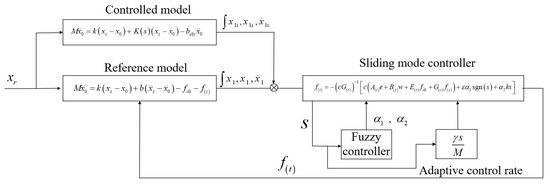
Figure 11.
Model referring to the block diagram of AFSMC.
5.2. Performance Analysis of Seat-Controllable Inertial Suspension
During the optimization process, the road input is characterized by a Class C stochastic surface, which is simulated to move at a velocity of 20 m/s. The road’s roughness coefficient, , is , as in Equation (15). Figure 12 shows the seat inertial suspension system performance control simulation results, comparing dynamic characteristics with the traditional suspension system.
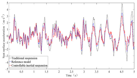
Figure 12.
Comparison of time domain to seat surface acceleration.
Figure 12 and Table 7 provide a comparative analysis between the traditional suspension and the second-order skyhook seat inertial suspension system, highlighting distinct performance characteristics. The controlled inertial suspension system reduces the surface acceleration value of the seat by 29.9%. The seat surface acceleration performance of the controllable seat inertial suspension system was significantly improved, and the deviation between the controllable suspension and the second-order skyhook seat inertial suspension is only 2.7%, achieving a good control effect. The comfort of the seat is less affected by changes in the RMS value of the suspension workspace, so a 7% change has little effect on comfort.
Table 7.
Comparison of RMS values of performance index.
From Figure 13, it can be seen that the seat acceleration PSD of the controllable seat inertial suspension system is consistently lower than the traditional one in the range of middle- and low-frequency ranges, and particularly in the low-frequency range. The PSD of seat acceleration of the controlled system is comparable to that of traditional suspension at high frequencies. The controllable seat inertial suspension system effectively suppresses seat surface acceleration across a broader frequency spectrum, and effectively suppresses the propagation of low-frequency vibration from the seat suspension system to the human body, helping to mitigate potential harm to individuals.
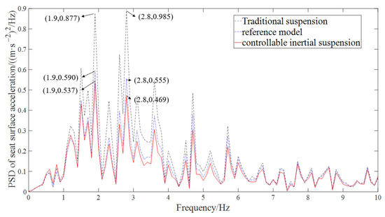
Figure 13.
Comparison of the PSD to the PSD of seat surface acceleration.
The performance comparison between the traditional suspension system and the seat-controllable inertial suspension under road surface impact conditions is shown as Figure 14.
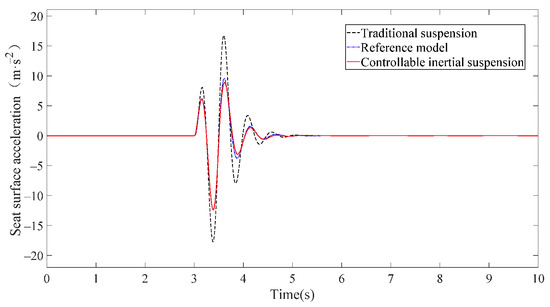
Figure 14.
Acceleration of seat surface under impact excitation.
In Figure 14, it is demonstrated that the second-order adaptive skyhook seat inertial suspension control system, enhanced with a sliding-mode observer for interference compensation, exhibits significant performance improvements over the uncontrolled seat suspension. Specifically, the peak seat surface acceleration was reduced by 43.1%. In addition, the seat suspension displacement between peaks were reduced by 34.7%. These enhancements contribute to an improved ride comfort for the driver. Figure 12 and Figure 13 present the tracking effect diagrams for the controller, which illustrate the AFSMC’s robust tracking performance, indicating that the actual model closely follows the reference model.
Sine excitation can be used to evaluate the vibration response characteristics of the seat suspension system at a particular frequency. Road excitation is shown in Figure 15.
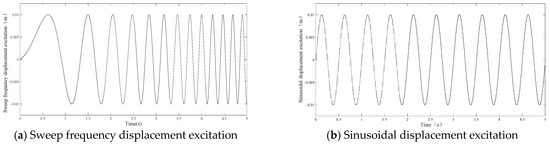
Figure 15.
Road excitation.
The displacement amplitude of the sweep signal is 0.01 m, and the frequency range is 0.1–5.0 Hz. In Figure 16a, as you can see, the controllable seat inertial suspension system’s acceleration spectrum is significantly reduced.
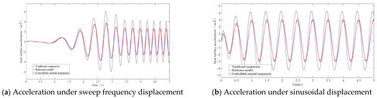
Figure 16.
Acceleration of seat surface.
As shown in Figure 16b, the controllable seat suspension system’s surface acceleration is significantly lower, and the inertia of controllable seat suspension system was reduced by 36%, such as Table 8.
Table 8.
Performance indexes under 2 Hz of sinusoidal excitation.
Through the analysis of suspension performance under sinusoidal excitation input, it becomes evident that the controllable seat inertial suspension system responds more quickly and enters the isolation zone earlier than the traditional system, and the peak value of vibration transmissibility is, obviously, decreased. The controllable seat inertia system significantly reduces the natural frequency of the suspension system.
6. Conclusions
By integrating the ideal skyhook inertial control with the positive real network into the suspension system (including the inerter), this study presents a comprehensive optimization approach aimed at reducing seat surface acceleration in the low-frequency range. The coupling mechanism between the two is studied, and the constraint conditions for seat inertial suspension optimization are established. Through the optimization algorithm and the application of Foster’s reactance theorem, the system parameters of the seat inertial suspension are successfully calculated. Subsequently, the mechanical configuration for the seat inertial suspension was deduced. Research on first- and second-order skyhook inertial mechanisms shows that the ideal second-order skyhook inertial seat suspension significantly reduces acceleration of the seat surface. Furthermore, theoretical validation has confirmed that the application of skyhook inertia in the second-order inertial suspension seat system, enhancing its performance, particularly in the low-frequency range, by significantly reducing seat surface acceleration.
Given the multitude of components within the second-order skyhook seat inertial suspension system, this paper introduces AFSMC. The dynamic difference between the actual model and the reference model is adjusted with the sliding-mode controller, and the suspension performance under random and impact road excitation is strictly simulated. Simulations show that the structure significantly optimizes seat surface acceleration, thereby improving ride comfort. The seat inertial suspension system fully utilizes the advantages of inertial suspension and skyhook inertial control, effectively optimizing the driver’s ride comfort and reducing driver fatigue.
Author Contributions
Conceptualization, X.Y., Y.Y. and R.S.; data curation, R.S. and C.L.; formal analysis, R.S., C.L. and Y.Y.; funding acquisition, X.Y.; investigation, R.S., Y.Y. and J.H.; methodology, X.Y. and Y.Y.; project administration, X.Y.; resources, R.S., Y.Y. and J.H.; software, R.S.; supervision, X.Y.; validation, X.Y., R.S. and Y.Y.; visualization, R.S. and Y.L.; writing—original draft, R.S. and Y.Y.; writing—review and editing, C.L. All authors have read and agreed to the published version of the manuscript.
Funding
This research was supported by the National Natural Science Foundation of China (Grant No. 52072157, 52202471), Jiangsu Province, and the Education Ministry Co-Sponsored Synergistic Innovation Center of Modern Agricultural Equipment (Grant No. XTCX2022), supported by the Fund of State Key Laboratory of Advanced Design and Manufacturing Technology for Vehicles, Hunan University (82315004).
Data Availability Statement
The original contributions presented in this study are included in the article. Further inquiries can be directed to the corresponding author.
Conflicts of Interest
The authors declare no conflicts of interest.
References
- Kuang, H.; Qiu, Y.; Liu, C.; Zheng, X. A nonlinear biodynamic model of seated human body exposed to vertical vibration with sensitivity analysis. Mech. Syst. Signal Process. 2023, 204, 110758. [Google Scholar] [CrossRef]
- Kia, K.; Johnson, P.W.; Kim, J.H. The effects of different seat suspension types on occupants’ physiologic responses and task performance: Implications for autonomous and conventional vehicles. Appl. Ergon. 2021, 93, 103380. [Google Scholar] [CrossRef] [PubMed]
- Stanczyk, T.L.; Zuska, A. Application of anthropodynamic dummies for evaluating the impact of vehicle seat vibrations upon human body. J. Theor. Appl. Mech. 2015, 53, 1029–1039. [Google Scholar] [CrossRef][Green Version]
- Zuska, A.N.D.R.Z.E.J.; Stanczyk, T.L. Review of anthropodynamic dummies used to evaluate the effect of vibrations on sitting human (vehicle driver). Archiwum Motoryzacji 2014, 65, 65–74. [Google Scholar]
- Zuska, A.; Stanczyk, T.L. Analysis of the impact of selected anthropometric parameters on the propagation of vertical vibration in the body of a seated person (driver). J. Vibroeng. 2015, 17, 3936–3948. [Google Scholar]
- Heidarian, A.; Wang, X. Review on Seat Suspension System Technology Development. Appl. Sci. 2019, 9, 2834. [Google Scholar] [CrossRef]
- Zhang, X.; Wang, C.; Guo, K.; Sun, M.; Yao, Q. Dynamics modeling and characteristics analysis of scissor seat suspension. J. Vib. Control 2017, 23, 2819–2829. [Google Scholar] [CrossRef]
- Ning, D.; Sun, S.; Du, H.; Li, W. Integrated active and semi-active control for seat suspension of a heavy duty vehicle. J. Intell. Mater. Syst. Struct. 2018, 29, 91–100. [Google Scholar] [CrossRef]
- Du, H.; Li, W.; Zhang, N. Vibration control of vehicle seat integrating with chassis suspension and driver body model. Adv. Struct. Eng. 2013, 16, 1–9. [Google Scholar] [CrossRef]
- Zhao, L.; Zhou, C.; Yu, Y.; Yang, F. An analytical formula of driver RMS acceleration response for quarter-car considering cushion effects. Veh. Syst. Dyn. 2017, 55, 1283–1296. [Google Scholar] [CrossRef]
- Song, Y.; Chen, L.; Yang, T. Geometrically nonlinear inerter for vibration suppression. Appl. Math. Mech. 2023, 44, 1871–1886. [Google Scholar] [CrossRef]
- Yang, M.; Luo, X.; Zhang, X.; Ding, H.; Chen, L. Enhancing suspension vibration reduction by diagonal inerter. Appl. Math. Mech. 2022, 43, 1531–1542. [Google Scholar] [CrossRef]
- Ning, D.; Du, H.; Sun, S.; Li, W.; Li, W. An energy saving variable damping seat suspension system with regeneration capability. IEEE Trans. Ind. Electron. 2018, 65, 8080–8091. [Google Scholar] [CrossRef]
- Gad, S.; Metered, H.; Bassuiny, A.; Abdel Ghany, A.M. Multi-objective genetic algorithm fractional-order PID controller for semi-active magnetorheologically damped seat suspension. J. Vib. Control 2017, 23, 1248–1266. [Google Scholar] [CrossRef]
- Liu, P.; Ning, D.; LUO, L.; Zhang, N.; Du, H. An electromagnetic variable inertance and damping seat suspension with controllable circuits. IEEE Trans. Ind. Electron. 2021, 69, 2811–2821. [Google Scholar] [CrossRef]
- Cui, L.; Xue, X.; Le, F.; Mao, H.; Ding, S. Design and experiment of electro hydraulic active suspension for controlling the rolling motion of spray boom. Int. J. Agric. Biol. Eng. 2019, 12, 72–81. [Google Scholar] [CrossRef]
- Zhang, Y.; Ren, C.; Ma, K.; Xu, Z.; Zhou, P.; Chen, Y. Effect of delayed resonator on the vibration reduction performance of vehicle active seat suspension. J. Low Freq. Noise Vib. Act. Control 2022, 41, 387–404. [Google Scholar] [CrossRef]
- Zhang, X.; Liu, X.; Sun, C. Research on a novel displacement-dependent semi-active valve damping control mechanism used in the seat suspension system. Adv. Mech. Eng. 2023, 15, 1–17. [Google Scholar] [CrossRef]
- Smith, M.C. Synthesis of mechanical networks: The inerter. IEEE Trans. Autom. Control 2002, 47, 1648–1662. [Google Scholar] [CrossRef]
- Dai, J.; Gai, P.P.; Xu, Z.D.; Huang, X.H. Inerter location effect on the generalized tuned mass damper inerter control. Structures 2023, 58, 105517. [Google Scholar] [CrossRef]
- Shen, Y.; Qiu, D.; Yang, X.; Chen, J.; Guo, Y.; Zhang, T. Vibration isolation performance analysis of a nonlinear fluid inerter-based hydro-pneumatic suspension. Int. J. Struct. Stability Dyn. 2024. [Google Scholar] [CrossRef]
- Yang, Y.; Liu, C.; Lai, S.K.; Chen, Z.; Chen, L. Frequency-dependent equivalent impedance analysis for optimizing vehicle inertial suspensions. Nonlinear Dyn. 2024, 1–26. [Google Scholar] [CrossRef]
- Desai, R.; Guha, A.; Seshu, P. Modelling and simulation of active and passive seat suspensions for vibration attenuation of vehicle occupants. Int. J. Dynam. Control 2021, 9, 1423–1443. [Google Scholar] [CrossRef]
- Patel, C.C. Shared mass damper linking adjacent structures subjected to random excitation. Structures 2023, 56, 104869. [Google Scholar] [CrossRef]
- Zhang, Y.; Hu, N.; Cheng, Z.; Zhang, L.; Chen, H. Dynamic Modeling of the Aircraft Landing Gear Based on ISD Mechanism. In Proceedings of the 2018 Prognostics and System Health Management Conference PHM-Chongqing, Chongqing, China, 26–28 October 2018; pp. 344–349. [Google Scholar] [CrossRef]
- Li, Y.; Jiang, J.Z.; Sartor, P.; Neild, S.A.; Wang, H. Including inerters in aircraft landing gear shock strut to improve the touch-down performance. Procedia Eng. 2017, 199, 1689–1694. [Google Scholar] [CrossRef]
- Wu, H.; Gong, N.; Yang, J.; Gong, L.; Li, W.; Sun, S. Investigation of a semi-active suspension system for high-speed trains based on magnetorheological isolator with negative stiffness characteristics. Mech. Syst. Signal Process. 2024, 208, 111085. [Google Scholar] [CrossRef]
- Chen, X.; Shen, L.; Hu, X.; Li, G.; Yao, Y. Suspension parameter optimal design to enhance stability and wheel wear in high-speed trains. Veh. Syst. Dyn. 2024, 62, 1230–1252. [Google Scholar] [CrossRef]
- Zhang, H.; Ling, L.; Zhai, W.; Wang, K. An active suspension system for enhancing running safety of high-speed trains under strong crosswind. Proc. Inst. Mech. Eng. Part F J. Rail Rapid Transit 2024, 238, 544–558. [Google Scholar] [CrossRef]
- Ali, S.A.; Metered, H.; Bassiuny, A.M.; Ghany, A.A. Theoretical investigation of the rail vehicle suspension system using different optimised controllers by harmony search algorithm incorporating magnetorheological dampers. Int. J. Veh. Perform. 2024, 10, 144–176. [Google Scholar] [CrossRef]
- Shen, W.; Long, Z.; Cai, L.; Niyitangamahoro, A.; Zhu, H.; Li, Y.; Qiu, C. An inerter-based electromagnetic damper for civil structures: Modeling, testing, and seismic performance. Mech. Syst. Signal Process. 2022, 173, 109070. [Google Scholar] [CrossRef]
- Ma, R.; Bi, K.; Hao, H. Inerter-based structural vibration control: A state-of-the-art review. Eng. Struct. 2021, 243, 112655. [Google Scholar] [CrossRef]
- Liu, C.; Chen, L.; Lee, H.P.; Yang, Y.; Zhang, X. A review of the inerter and inerter-based vibration isolation: Theory, devices, and applications. J. Frankl. Inst. 2022, 359, 7677–7707. [Google Scholar] [CrossRef]
- Jereczek, B.; Maciejewski, I.; Krzyzynski, T.; Krolikowski, T. Implementation of the SMC control strategy to an active horizontal seat suspension system. Procedia Comput. Sci. 2023, 225, 3527–3535. [Google Scholar] [CrossRef]
- Li, Y.; Yang, X.; Shen, Y.; Liu, Y.; Wang, W. Optimal design and dynamic control of the HMDV inertial suspension based on the ground-hook positive real network. Adv. Eng. Softw. 2022, 171, 103171. [Google Scholar] [CrossRef]
- Jeong, Y.; Yim, S. Design of Active Suspension Controllers for 8 × 8 Armored Combat Vehicles. Machines 2024, 12, 931. [Google Scholar] [CrossRef]
- Esmaeial, J.S.; Akbari, A.; Farnam, A.; Azad, N.L.; Crevecoeur, G. Adaptive Neuro-Fuzzy Control of Active Vehicle Suspension Based on H2 and H∞ Synthesis. Machines 2023, 11, 1022. [Google Scholar] [CrossRef]
- Deng, L.; Sun, S.; Christie, M.; Ning, D.; Jin, S.; Du, H.; Li, W. Investigation of a seat suspension installed with compact variable stiffness and damping rotary magnetorheological dampers. Mech. Syst. Signal Process. 2022, 171, 108802. [Google Scholar] [CrossRef]
- Wang, S.; Hui, Y.; Sun, X.; Shi, D. Neural network sliding mode control of intelligent vehicle longitudinal dynamics. IEEE Access 2019, 7, 162333–162342. [Google Scholar] [CrossRef]
- Jereczek, B.; Maciejewski, I.; Krzyżyński, T.; Królikowski, T. Modeling and simulation of the horizontal seat suspension system under random vibration. Procedia Comput. Sci. 2022, 207, 858–866. [Google Scholar] [CrossRef]
- Jiang, J.Z.; Smith, M.C. Regular positive-real functions and five-element network synthesis for electrical and mechanical networks. IEEE Trans. Autom. Control 2011, 56, 1275–1290. [Google Scholar] [CrossRef]
- Čakmak, D.; Tomičević, Z.; Wolf, H.; Božić, Ž.; Semenski, D.; Trapić, I. Vibration fatigue study of the helical spring in the base-excited inerter-based isolation system. Eng. Fail. Anal. 2019, 103, 44–56. [Google Scholar] [CrossRef]


Disclaimer/Publisher’s Note: The statements, opinions and data contained in all publications are solely those of the individual author(s) and contributor(s) and not of MDPI and/or the editor(s). MDPI and/or the editor(s) disclaim responsibility for any injury to people or property resulting from any ideas, methods, instructions or products referred to in the content. |
© 2025 by the authors. Licensee MDPI, Basel, Switzerland. This article is an open access article distributed under the terms and conditions of the Creative Commons Attribution (CC BY) license (https://creativecommons.org/licenses/by/4.0/).