Abstract
Biomimetic knee exoskeletons often struggle to balance accurate replication of joint biomechanics with efficient torque transmission. This study presents a knee exoskeleton featuring a single-stage planetary gear set with three coupled interface gears to reproduce the coupled rolling–sliding motion of the human knee. By mapping rolling and sliding displacements into distinct gear-driven motions, the design achieves a near-linear relationship approximating the physiological J-shaped instantaneous center of rotation (ICR). Gear parameters were optimized under biomechanical and engineering constraints, producing a compact, manufacturable configuration with ICR deviation ≤ 5 mm (sliding distance). Performance experience demonstrates that the optimized joint reduced sliding misalignment of the contact point by 73.4%, delivered peak output torque in agreement with predictions, and maintained an average efficiency of 95.4% across operating speeds. These findings confirm that the proposed mechanism enhances kinematic fidelity and actuation performance, offering a promising solution for next-generation rehabilitation exoskeletons.
1. Introduction
Lower-limb exoskeletons have become an important research direction in wearable robotics, aiming to restore or augment human mobility by providing external torque assistance during locomotion and rehabilitation. Continuous advances in actuation technology, control strategy, and lightweight structural design have enabled the development of portable and ergonomic exoskeletons that can reduce muscular effort and support gait rehabilitation for individuals with neurological disorders or age-related weakness [1,2,3]. A key requirement for natural human–robot interaction is the high biomimetic fidelity of joints, which ensures minimal joint misalignment, correct power transmission, and enhances user comfort.
Among lower-limb joints, the knee is biomechanically critical for body support, shock absorption, and energy transfer [4,5,6]. However, accurately reproducing knee complex rolling–sliding articulation remains a key challenge for achieving natural human–robot interaction and minimizing misalignment-induced discomfort. Unlike a simple hinge, the human knee exhibits a coupled rolling–sliding motion between the femoral and tibial condyles [7,8], generating a non-fixed instantaneous center of rotation (ICR) that traces a J-shaped trajectory during flexion–extension [9]. Conventional single-axis exoskeleton knees fail to capture this feature, resulting in geometric mismatch, skin shear, and abnormal torque peaks during walking [7].
To emulate natural knee biomechanics, researchers have explored linkage-, cam-, and gear-based designs. Multi-bar linkages emulate cruciate ligament function via dynamic ICR shifts and have found applications in both prosthetic and exoskeleton systems [3,10]. Cam-based designs mimic femoral condyle geometry and tibial rotation [11], yet often remain passive and inefficient. Recently, origami-inspired soft mechanisms have achieved biomimetic polycentric rotation with reduced mass and structural simplicity [12]. In parallel, gear-based mechanisms provide a promising alternative due to their high torque density, mechanical robustness, and efficient power transmission. Recent research has explored different gear systems to mimic polycentric knee motion [13,14,15,16].
Despite these advancements, existing biomimetic knee exoskeletons still face notable limitations. Linkage- and cam-based mechanisms, while structurally simple, often compromise transmission efficiency and active torque output [17,18]. Gear-based designs, although more accurate in reproducing knee kinematics, are frequently constrained by intermediate transmission elements (belt or cable) that reduce energy utilization and limit responsiveness [19,20]. These challenges highlight a critical gap between replicating knee biomechanics and achieving efficient, high-torque actuation suitable for rehabilitation and assistive applications.
Therefore, an effective biomimetic knee mechanism should simultaneously achieve kinematic accuracy, high transmission efficiency, and proximal mass distribution, ensuring both biomechanical realism and wearability. Motivated by these challenges, this study proposes a gear-based biomimetic knee mechanism that decomposes the tibiofemoral motion into two coordinated gear-driven variables. By coupling a planetary gear stage with a three-stage external gear train, the mechanism aims to emulate the natural rolling–sliding ratio of the human knee and achieve the optimal transmission parameters balancing compactness, efficiency, and alignment fidelity.
Through this investigation, the proposed design aims to bridge the gap between anatomical joint mechanics and engineering implementation, providing a systematic basis for developing high-efficiency, anatomically compatible exoskeletons. The main contributions of this work are summarized as follows:
- A novel rolling-gear biomimetic knee mechanism is proposed to replicate the coupled rolling–sliding kinematics of the tibiofemoral joint with an accurately traceable J-shaped ICR trajectory.
- A multi-stage transmission structure integrating planetary and three coupled interface gears is designed to maximize torque density while maintaining compactness and mechanical efficiency.
- A virtual interaction framework is formulated to quantify geometric alignment under biomechanical constraints.
- Experimental validation is conducted to evaluate mechanical performance, kinematic accuracy, and efficiency in comparison with representative biomimetic knee mechanisms.
The remainder of this paper is organized as follows: Section 2 presents the mechanical design and working principle of the proposed rolling-gear knee mechanism and the optimization framework and numerical simulations. Section 3 describes the experimental setup and validation results. Section 4 discusses the performance comparison and potential improvements.
2. Materials and Methods
Based on the design rationale outlined in Section 1, this section introduces the mechanical architecture and working principle of the proposed rolling-gear biomimetic knee mechanism. The methodological framework includes: (i) mapping knee biomechanics into rolling and sliding components; (ii) constructing a mathematical model of the dual-gear mechanism; (iii) optimizing gear parameters under biomechanical and engineering constraints; and (iv) validating the effect of optimal gear parameters on ICR trajectory fidelity. The following subsections describe these processes in detail.
2.1. Mapping of Knee Biomechanics
Human knee motion during flexion and extension involves a coupled rolling–sliding interaction between the femoral condyles and the tibial plateau [19]. As illustrated in Figure 1a, the knee flexion-extension angle is defined as the included angle between the femoral and tibial anatomical axes, which intersect at the contact point . The femoral axis is drawn through the center of the femoral condyle and the hip joint center (approximated by the mass point, ), while the tibial axis passes through toward the shank’s center of mass (). The resulting intersection angle represents the knee joint configuration during motion. When the femoral axis rotates posteriorly relative to the tibial axis around the contact point , the angle increases, indicating knee flexion; conversely, anterior rotation leads to a reduction in , corresponding to knee extension.
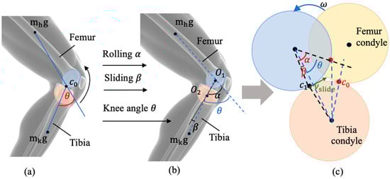
Figure 1.
Geometric modeling of the human knee joint based on coupled rolling–sliding motion. (a) The initial configuration of the femoral and tibial condyles; (b) Rolling–sliding decomposition of knee biomechanics; (c) Equivalent geometric model illustrating the coupled motion of the femoral and tibial condyles.
Following the rolling–sliding coupling mechanism, the knee joint motion can be further defined from the perspective of the femoral–tibial contact geometry. In Figure 1b, the femoral and tibial condyles are approximated as two interacting circular arcs with centers (femur) and (tibia), respectively, and a common contact point C. The vectors and represent the instantaneous orientations of the femoral and tibial surfaces. The knee joint angle is defined as the included angle between these two vectors,
which describes the relative rotation of the femur with respect to the tibia at the contact point.
To further characterize the coupled rolling–sliding motion, two auxiliary variables are defined: rolling angle (, the angular rotation of the femoral condyle about its center), sliding angle (, corresponding to the relative tangential displacement () along the contact interface), normalized by the equivalent curvature radius
where and denote the radii of the femoral and tibial condylar surfaces, respectively.
The overall knee flexion–extension angle is then expressed as a linear combination of the rolling and sliding components:
with denoting the relative tangential sliding velocity between the two condylar surfaces. By defining (rolling) and (sliding) within the same contact-based geometric framework, the knee joint angle can be quantitatively related to the coupled rolling–sliding behavior.
On this anatomical basis, the mechanism of the same angular change can be explained through the femoral–tibial contact model shown in Figure 1c. In this geometric abstraction, the femoral and tibial condyles are approximated as two circular profiles with centers and . Their instantaneous contact points and define the microscopic origin of the macroscopic knee joint rotation. Within this local framework, the rotation of the femoral condyle about its own center is characterized by , while the relative tangential displacement between the two condyles corresponds to . These two micro-motions together produce the macroscopic knee flexion–extension angle through the relationship.
This geometric representation quantitatively links the knee joint angle to the instantaneous configuration of the femoral and tibial condyles, establishing an analytical bridge between anatomical motion and the mechanical modeling framework adopted in this study. To reproduce the same geometric biomechanics within a knee exoskeleton, a corresponding mechanism was developed that maps the coupled motion into two distinct gear-driven variables: , representing the rolling component captured by the planetary gear system, and , representing the sliding component captured by the three-stage external gear train. The design objective is to faithfully reconstruct the natural rolling–sliding coupling of the human knee, thereby achieving high kinematic fidelity in the exoskeleton’s joint motion.
2.2. Design and Optimization of the Gear-Based Biomimetic Knee Exoskeleton
To address misalignment between the human knee ICR and the exoskeleton’s mechanical axis, a compound planetary differential transmission with three coupled gear interface mechanisms was developed. The system integrates a planetary gear system that replicates the rolling displacement () of the femoral condyles, and a three-stage external gear train that reproduces the sliding displacement () of the tibial plateau. This gear-based solution was selected for two principal advantages: (i) the ability to stabilize the transmission ratio that governs the – relationship, and (ii) high transmission efficiency under direct-drive actuation, ensuring sufficient torque for rehabilitation tasks.
The transmission system adopted in the proposed exoskeleton knee joint is a planetary mechanism integrated with three coupled interface gears, as illustrated in Figure 2. The core planetary system consists of the sun gear (S), planet gear (P), ring gear (R), and planet carrier (C), which together form the fundamental unit. Around this unit, gears 1, 2, and 3 are coupled to distinct members of the planetary system to achieve successive torque transfer and compact multi-output functionality.
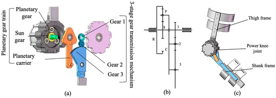
Figure 2.
Structure and configuration of the bioinspired gear-rolling knee joint. (a) Key components of a planetary gear set with three coupled interface gears; (b) Kinematic diagram of the transmission; (c) Integration of the power knee joint into the exoskeleton prototype.
In this configuration, the S is driven by the input shaft, the P meshes simultaneously with S and R, and the C supports the planet set. The motion of each element follows the standard planetary-gear relationship expressed by the Willis equation:
where , , and denote the angular velocities of the ring, sun, and carrier, respectively, and and are their corresponding numbers of teeth.
The absolute angular velocity of any gear mounted on the carrier can thus be expressed as the superposition of the carrier motion and its relative rotation with respect to the carrier,
where represents gears 2, or 3.
The planetary gear train simulates the rolling motion. The angular is expressed as:
Due to the ring gear being fixed () and the sun gear serves as the input, the angular velocity of the carrier is derived from the Willis equation as
The three coupled interface gears (gears 1–3) simulate the sliding motion. The angular β is expressed as:
Since gears 1, 2, and 3 are coaxially mounted with the carrier through external meshing relationships, their angular velocities can be expressed as
Equivalently, their relative (carrier-frame) angular velocities are
where , represent the teeth numbers of gears 2 and 3, respectively.
From Equations (6)–(10), the rolling–sliding relative angular ratio can be derived as:
Because these three gears interact through the common planetary unit rather than through direct meshing, the overall transmission behaves as a single-stage planetary system with three functional interfaces. The equivalent transmission ratio between input and output can be derived as
Thus, the effective output torque at the exoskeleton knee joint is
2.3. Optimization and Comparison Analysis
2.3.1. Modeling of the Limb–Exoskeleton Coupled System
To further analyze the kinematic compatibility between the human limb and the proposed exoskeleton mechanism, a comprehensive simulation model was constructed. Building upon the previously established rolling–sliding coupling principle of the knee joint, the model integrates both the biological limb biomechanics and the mechanical exoskeleton dynamics within a unified framework. It is noted that the misalignment caused by the inconsistent implementation of ICR between the human knee joint and the joint of the exoskeleton is visualized as the sliding distance of the exoskeleton frame along the human limb and serves as the minimum sliding distance as the quantization factor to compare their biomimetic performance. All the quantification is implemented on a virtual human–exoskeleton coupling model established in MATLAB/Simulink R2023a (MathWorks Inc., Natick, MA, USA). The modeling process of the limb–exoskeleton coupling system is illustrated in Figure 3.
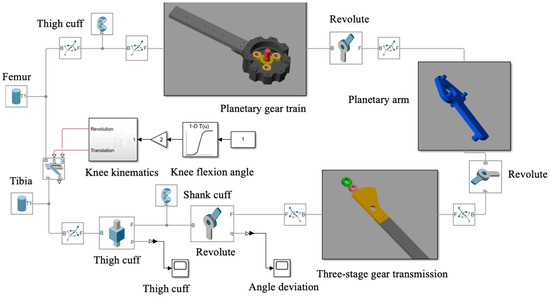
Figure 3.
Human–machine kinematics modeling of misalignment effect.
In this simulation framework, the human limb is modeled as a two-degree-of-freedom (2-DOF) anatomical knee joint, which characterizes the tibiofemoral motion through a combination of rolling and sliding between the femoral and tibial condyles. The femoral condyle is represented by a circular contact surface that rolls and slides over a fixed tibial plane, thereby reproducing the hybrid motion observed in natural flexion–extension cycles. The exoskeleton is modeled as a rigid multi-link mechanism comprising thigh and shank frames that correspond to the human femur and tibia. The thigh frame is fixed to the femur through the thigh cuff, while the shank frame is connected to the tibia via a shank cuff. The mechanical knee joint integrates a planetary gear train and a three-stage external gear transmission, which together generate the exoskeleton knee motion.
To define the human–exoskeleton kinematic interaction, the connection between the biological and mechanical structures is abstracted as a virtual prismatic–prismatic–revolute (P–P–R) kinematic chain. As depicted in Figure 4a, the two prismatic pairs (P) represent the small sliding motions permitted at the thigh and shank cuffs, while the revolute joint (R) corresponds to the exoskeleton’s mechanical rotation center. And the shank cuff (S) is selected as the critical evaluation node for analyzing relative displacement. The translational displacement of this point along the shank limb is used as a quantitative metric to assess joint misalignment within the coupled system.
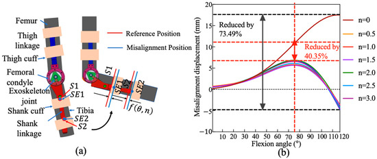
Figure 4.
Simulated misalignment displacement under varying gear parameters. (a) Schematic of the human–exoskeleton coupled knee model; (b) Misalignment displacement versus knee flexion angle for different rolling ratios.
Within the complete integrated model, the closed-loop kinematic chain consists of seven rigid bodies: two biological segments (thigh and shank), two exoskeleton linkages (thigh and shank frames), and three joint elements (1-DOF biological knee joint, 1-DOF exoskeleton knee joint, and 1-DOF prismatic joint). This unified model enables simulation of the joint coordination, transmission dynamics, and angle offset behavior under different flexion–extension conditions, providing a foundation for analyzing alignment performance and interaction dynamics between the user and the exoskeleton.
2.3.2. Kinematic Analysis Based on Misalignment Sliding
Equation (4) confirms that by selecting an appropriate near-linear mapping between α and β, the exoskeleton could accurately replicate the natural rolling–sliding trajectory of the knee joint. Within this modeling environment, the speed ratio -defined by the ratio of angular velocities derived from the meshing gear tooth counts-is employed as the primary design variable to evaluate the biomimetic performance of the proposed rolling–sliding knee joint mechanism. This parameter controls the relative contribution of rolling () and sliding () to the total joint motion ().
Figure 4b presents the simulation results of misalignment for multiple gear train configurations that incorporate both planetary and three-stage gear transmissions. The analysis reveals that the misalignment distance remains remarkably consistent across varying gear ratios. This suggests that the gear-based design provides robust kinematic tracking of the natural tibiofemoral trajectory. Compared to the baseline configuration with a single-axis revolute joint , the proposed rolling–sliding mechanism achieved a substantial reduction in misalignment. Specifically, the average displacement is reduced by approximately 73.49% at the maximum flexion angle of the human knee () and by 40.35% at the typical peak knee flexion angle during walking ().
2.3.3. Optimization of Gear Parameters
The gear parameters were optimized to ensure both kinematic fidelity and efficient torque transmission. The design variables included the tooth numbers of the sun gear (), ring gear (), and the three external gears (, , ). Several engineering constraints were imposed to guide the optimization: (i) the ICR trajectory of the exoskeleton joint had to approximate the theoretical J-shaped curve with an error less than ±10%, ensuring biomechanical fidelity; (ii) the system needed to generate peak torques greater than input torque, which are sufficient for adult gait assistance during stance; (iii) the total housing width was constrained to less than 60 mm to preserve compactness and wearability; and (iv) manufacturability rules demanded integer gear tooth numbers of 12 to avoid undercutting and ensure smooth meshing.
In the optimization process, denotes the desired design ratio derived from the theoretical rolling–sliding relationship, while represents the actual transmission ratio determined by the practical gear-tooth configuration. Since the number of teeth on each gear must be an integer, the tooth counts calculated from a given may not be realizable. Consequently, each theoretical n must be approximated by the nearest feasible integer tooth combination, producing a corresponding .
This integer rounding leads to a small deviation between the theoretical and realizable ratios, which further causes a difference in the displacement of the instantaneous meshing point (i.e., the misalignment between the human ICR and the mechanical rolling center). To determine the optimal number of teeth at a specific ratio, an evaluation function is defined as the difference between the minimum misalignment displacement obtained under and that under :
where denotes the sliding misalignment at a given knee-flexion angle .
To enable direct comparison between different gear configurations and the theoretical knee trajectory in the simulation model, the femoral and tibial condyles are approximated as two interacting circular arcs that represent the curvature of the posterior femoral condyle and the tibial plateau, respectively. The femoral condyle radius () and tibial condyle radius ()correspond directly to the radii of the two circles. To enable direct comparison between different gear configurations and the theoretical knee trajectory, Typical values were chosen as and , consistent with average adult knee morphology reported in biomechanical literature [17]. Accordingly, the normalized coordinates of the ICR are expressed as
At each flexion angle , the instantaneous contact point C between these arcs is calculated from the rolling–sliding geometric relationship:
where and denote the rolling and sliding angles of the femoral and tibial arcs, respectively. The ICR is determined as the intersection of the normal lines drawn from the femoral and tibial centers ( and ) through the contact point C. As varies from 0° to 120°, the locus of these intersection points forms the theoretical J-shaped trajectory (black dashed line in Figure 5).
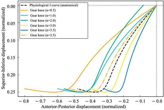
Figure 5.
ICR Trajectories: Gear-based Knee vs. Anatomical J-curve.
For the proposed gear-based knee mechanism, the same computation was repeated using the gear-derived - mapping defined in Equations (6)–(11), generating the corresponding mechanical ICR trajectories. As shown in Figure 5, when (orange solid line), sliding displacement dominates, leading to excessive posterior deviation and a translation-like trajectory. At and , rolling displacement dominates, anterior–posterior motion is compressed, and the trajectory becomes increasingly rotation-like. The optimized ratio produces the closest approximation to the theoretical curve, demonstrating high kinematic fidelity of the rolling-gear mechanism.
The final optimized gear parameters are listed in Table 1. This configuration ensures that the ICR trajectory deviation is less than 10%, gear-mesh efficiency of 96.7%, and a compact housing width of 57 mm. These results confirm that the proposed design faithfully reproduces the coupled rolling–sliding motion of the human knee while meeting engineering requirements for rehabilitation exoskeletons.

Table 1.
The optimized parameters of gears.
2.3.4. Simulation Validation of the Optimized Knee Mechanism
To evaluate the effectiveness of the proposed gear-based biomimetic knee joint, numerical simulations were performed using the optimized gear parameters listed in Table 2. The simulation results are shown in Figure 6. The maximum sliding displacement between the exoskeleton shank strap and the human shank less than 5 mm, while the angular deviation fluctuated within a range of −3° to +3°. Importantly, these deviations are minor and do not significantly affect practical wearing comfort or alignment. Therefore, the proposed exoskeleton mechanism successfully achieves its intended biomimetic objectives.
Table 2.
Biometric characteristics of the participants.
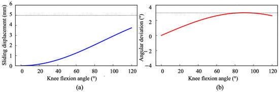
Figure 6.
The simulation results of optimized parameters of gears. (a) Relationship between knee flexion angle and sliding displacement; (b) Angular deviation between the human joint and gear-based joint.
3. Experiments and Results
3.1. Experimental Setup
A benchtop prototype of the optimized gear-based biomimetic knee joint was fabricated to validate the simulation results under real-world operating conditions. The experimental platform, shown in Figure 6a, consisted of a brushless DC motor (rated torque: 4 Nm, continuous power: 150 W) coupled directly to the sun gear of the planetary stage, the optimized planetary–external gear transmission (parameters listed in Table 2), and a custom exoskeleton knee frame for load application. An inline torque sensor (Futek, Irvine, CA, USA, accuracy ±0.2 Nm) and a high-resolution rotary encoder (2048 pulses per revolution) were integrated at the output shaft to measure joint torque and angular displacement, respectively. To monitor dynamic responses, additional inertial measurement units (IMUs, Xsens MTi-series, Xsens Technologies B.V., Enschede, The Netherlands) were mounted on the thigh and shank links to capture segmental kinematics.
Five healthy adults (age 22–29 years; body height 160–178 cm; body mass 60–75 kg) participated in the treadmill tests (baseline walking without the device, and walking with the device following predefined joint trajectories). All had no history of lower-limb musculoskeletal or neurological disorders and provided written informed consent, and protocols were approved by the institutional ethics committee. The sample represents healthy adults typically used for benchtop validation of wearable mechanisms. To facilitate reproducibility and enable anthropometry-sensitive interpretation, we recorded sex, leg dominance, and segment lengths; a summary table is provided (Table 2). Treadmill speed was kept within 0.8–1.0 m/s to limit between-trial variability and isolate the effect of the knee mechanism on kinematic compatibility. During walking trials, the predefined gait trajectories were scaled to individual leg lengths to ensure anthropometric consistency. Data were recorded for three consecutive gait cycles per condition, and each condition was repeated three times to ensure reproducibility. Consequently, the results primarily reflect the exoskeleton’s mechanical performance under healthy gait conditions.
3.2. Experimental Prototype
To enable quantitative evaluation of joint misalignment and ensure safe human–robot interaction, a sliding attachment mechanism was incorporated into the exoskeleton’s shank module. The connection between the user’s lower leg and the exoskeleton was designed as a sliding interface, capable of accommodating minor misalignments and soft-tissue deformation while maintaining consistent force transmission. Specifically, a linear slider–rail assembly was integrated along the sagittal axis of the shank frame, as shown in Figure 7a. The slider rail was rigidly fixed to the main exoskeleton structure, whereas a movable linear slider was mounted on the connection cuffs encircling the lower shank. The cuffs were fabricated from lightweight aluminum alloy and padded with medical-grade foam to ensure even pressure distribution around the limb. Both the slider and rail components were joined through a 3D-printed low-friction polymer interface (nylon-based composite, surface roughness < 0.4), allowing controlled axial translation (up to 20 ) during gait without introducing lateral instability. This design effectively absorbed minor alignment errors between the biological knee and the exoskeleton joint.
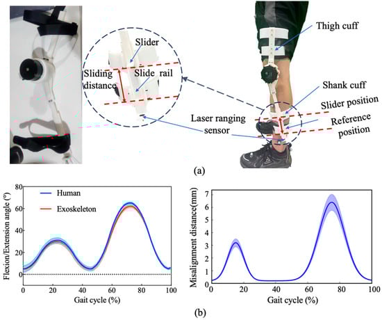
Figure 7.
The experimental setup and results of human–machine kinematic compatibility. (a) Configuration of the lower-limb exoskeleton prototype and measurement setup; (b) Joint motion comparison and misalignment evaluation during one gait cycle.
To monitor the relative displacement between the cuff and the exoskeleton frame, a set of laser ranging sensors (TOF050F, Zhending Atom Electronics Co., Ltd., Shenzhen, China; sampling rate 160 Hz, resolution 0.1 mm) was installed along the translation axis. These sensors continuously measured the sliding distance during walking trials, providing a direct quantitative indicator of joint alignment performance. Additionally, interface pressure sensors (thin-film FSRs, 0.2 mm thickness) were embedded within the anterior and posterior shank pads to record the distribution and variation in contact pressure during locomotion. The synchronized acquisition of displacement and pressure data enabled comprehensive evaluation of both kinematic compatibility and interaction comfort of the limb–exoskeleton attachment strategy throughout dynamic gait cycles.
Further, to evaluate the mechanical behavior of the proposed exoskeleton under repeatable conditions, a predefined gait trajectory control strategy was adopted. The control framework consists of a feedforward–feedback hybrid architecture. In the feedforward module, reference joint trajectories () and velocities () were extracted from averaged gait data of healthy adults (normalized to one gait cycle). These trajectories were stored as lookup tables parameterized by gait phase and synchronized with a treadmill. The feedback module employed a PD position controller for each actuator: expressed as , where and are proportional and derivative gains, respectively. This predefined trajectory approach ensured repeatable joint motion and enabled quantitative analysis of kinematic fidelity, torque efficiency, and transmission smoothness, independent of user-intent or adaptive control uncertainties.
3.3. Experimental Results
3.3.1. Verification of Human–Machine Kinematic Compatibility
ICR misalignment is evaluated in an experiment by introducing prismatic compliance at the cuffs. The shank frames provide continuous length adjustment. As illustrated in Figure 7, the kinematic knee joint trajectories from five subjects during gait cycles were recorded and analyzed under both conditions. Results revealed high trajectory similarity with correlation coefficients , indicating strong kinematic transparency between exoskeleton-assisted and natural movement. The mean angular deviation across the flexion-extension cycle was limited to , confirming the system’s precision in guiding limb motion along biomechanically appropriate paths. In terms of joint misalignment, the gear-based rolling knee joint achieved a maximum sliding displacement of , representing a 68.8% reduction compared to conventional single-axis hinge designs, which exhibited under similar conditions. This substantial improvement is attributed to the three-stage gear transmission mechanism, which effectively compensates for ICR deviation.
3.3.2. Evaluation of Human–Machine Attachment Interaction
To gauge energetic implications, we measured the additional sagittal-plane pressure distribution at the limb–exoskeleton interface during gait. Peak pressure and pressure-time integral (PTI) are reported. These measurements provide a biomechanical correlate of human–machine interaction forces, reflecting how alignment and kinematic fidelity influence localized mechanical loading and potential energy expenditure.
The sagittal-plane pressure distribution at the limb–exoskeleton interface was shown in Figure 8a. The heatmap reveals that interface pressure varies dynamically with the gait phase, with moderate loading during stance and a distinct high-pressure region approximately 55–60 kPa centered around 65% of the gait cycle, corresponding to the maximum knee-flexion angle. Such pressure peaks reflect transient increases in human–machine contact force and potential energy expenditure due to residual ICR deviation. Although this represents the highest localized loading throughout the cycle, its duration is short (<10% of the gait period) and its magnitude remains within the physiological comfort range reported in the literature [21]. The average interface pressure over a full gait cycle was approximately 25–30 kPa. The absence of participant discomfort reports during the trials further supports the physiological tolerability of the pressure levels.
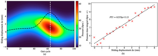
Figure 8.
Combined sagittal-plane interface pressure and human–machine interaction analysis. (a) Heatmap of sagittal-plane interface pressure at the limb–exoskeleton contact during one gait cycle; (b) Relationship between sliding displacement and pressure-time integral.
To quantify this effect, the relationship between sliding displacement () and PTI was examined across subjects (Figure 8b). A significant positive correlation (, ) was observed, indicating that larger relative sliding between the limb and exoskeleton produces higher cumulative interface loading. This finding supports the hypothesis that the measured sliding displacement serves as a biomechanical proxy for ICR misalignment, linking mechanical fidelity to metabolic cost.
Overall, these results demonstrate that minimizing through improved alignment and transmission optimization not only enhances user comfort but also reduces localized mechanical stress and energetic demand during assisted gait.
3.3.3. Torque and Efficiency Tests
To experimentally validate the torque and efficiency performance of the proposed gear-based biomimetic knee joint, a Xiaomi CyberGear micro-motor (Xiaomi Corporation, Beijing, China; rated torque: 4 Nm) was integrated with the optimized gear mechanism. The system achieved a total transmission ratio of , with a theoretical efficiency of approximately determined based on the ideal performance of the motor and gear. The theoretical maximum torque capacity was therefore calculated as:
This value represents the upper torque limit of the actuator-gear system and substantially exceeds the design requirement of 35–45 Nm for adult gait assistance.
Output torque was experimentally measured using an inline torque sensor mounted at the exoskeleton knee joint, while motor input torque and electrical power were recorded through the driver interface. Figure 9a shows the torque response under step-input excitation. Across five subjects and repeated gait cycles, the exoskeleton consistently delivered peak output torques in the range of 37–40 Nm, with an average of 39.1 Nm. These results closely match the design requirement and remain well below the theoretical maximum, thereby confirming the validity of the gear-based mechanism.
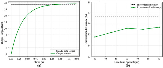
Figure 9.
Measured output torque response and transmission efficiency of the optimized knee mechanism. (a) Step-response of the exoskeleton knee torque under constant motor input.; (b) Transmission efficiency across various knee joint speeds.
Efficiency was computed as the ratio of mechanical output power (measured by the motor driver interface using voltage and current data) to input electrical power (measured using a torque sensor and joint velocity). Transmission efficiency results are summarized in Figure 9b. Across the tested speed range of 30–90 rpm at the knee joint, the optimized design achieved an average efficiency of 95.4%, only slightly lower than the predicted value of 96.7%. Minor deviations can be attributed to bearing friction and assembly tolerances in the prototype. Results indicate that the mechanism can sustain high-load operation without significant energy loss.
These findings demonstrate that the optimized gear-based knee mechanism not only enhances kinematic fidelity but also ensures robust torque output and high transmission efficiency, thereby meeting the critical requirements for wearable rehabilitation exoskeletons.
4. Discussion
This study presented a gear-based biomimetic knee mechanism designed to replicate the coupled rolling–sliding motion of the human knee while ensuring high torque capacity and transmission efficiency for rehabilitation exoskeletons. By integrating planetary and coupled interface gear trains, the mechanism decomposes knee biomechanics into rolling and sliding components and establishes a near-linear mapping between them. Optimization of gear parameters under biomechanical and engineering constraints yielded a gear set that minimized ICR trajectory and misalignment error, satisfied compactness and manufacturability requirements.
Simulation results confirmed that the optimized mechanism accurately reproduces the physiological instantaneous center of rotation (ICR) trajectory, reducing the kinematic misalignment between the exoskeleton and the user’s knee by over 70% compared with a conventional single-axis hinge. The optimized configuration maintained an ICR deviation below 10% of the theoretical J-shaped path, indicating strong biomechanical fidelity. Experimental evaluations further verified that the exoskeleton-assisted knee motion closely followed natural flexion–extension patterns with minimal phase lag. The system consistently delivered a peak torque of 39 Nm and achieved an average transmission efficiency of 95.4%, confirming that the mechanical design effectively balances high torque output and compact structure.
Despite incorporating a multi-stage gear train, the system’s weight distribution was carefully optimized to minimize distal inertia. All major actuation components were in a total mass of 1.7 kg, of which 1.35 kg is concentrated in the knee gear module. This configuration maintains the mass center near the anatomical joint, thereby reducing its influence on gait dynamics and improving user comfort. As summarized in Table 3, when compared with representative linkage-, cam-, RCM-, and cable-driven knee exoskeletons reported in recent literature, the proposed rolling-gear mechanism achieves the highest mechanical efficiency (95.4%) while maintaining comparable overall weight and compact structure.
Table 3.
Comparison of representative knee exoskeleton mechanisms.
These results demonstrate that the proposed rolling-gear architecture successfully bridges the gap between biomechanical fidelity and actuation efficiency. By localizing mass near the joint axis and reproducing the natural rolling–sliding coupling, the mechanism provides both accurate kinematic replication and high energy efficiency, establishing a promising foundation for next-generation wearable rehabilitation devices.
However, several mechanical limitations remain. The rigid multi-stage gearing, although efficient, contributes to increased structural stiffness and potential acoustic noise during continuous use. Future work will focus on lightweight material optimization (e.g., composite or magnesium alloys), noise damping through gear profile modification, and dynamic meshing analysis to quantify stiffness, damping, and backlash. In addition, forthcoming studies will evaluate long-term durability, cyclic wear characteristics, and human-in-the-loop metabolic effects under overground walking conditions. These efforts will further advance the integration of the proposed mechanism into a fully wearable and ergonomically optimized exoskeleton system.
Author Contributions
Conceptualization, H.L. and H.Y.; methodology, H.L.; software, M.L.; validation, H.L. and M.L.; formal analysis, Y.S.; investigation, D.X.; resources, H.Y. and R.K.-Y.T.; data curation, M.L.; writing—original draft preparation, H.L.; writing—review and editing, H.L.; visualization, Y.S. and D.X.; supervision, H.Y. and R.K.-Y.T.; project administration, H.Y. and R.K.-Y.T.; funding acquisition, H.L. All authors have read and agreed to the published version of the manuscript.
Funding
This research was funded by the Ministry of Science and Technology of the People’s Republic of China, grant number 2023YFC3604800, and the APC was funded by the Ministry of Science and Technology of the People’s Republic of China.
Data Availability Statement
The data presented in this study are available on request from the corresponding author. The data are not publicly available due to restrictions (they contain information that could compromise the privacy of research participants).
Conflicts of Interest
The authors declare no conflicts of interest.
Abbreviations
The following abbreviations are used in this manuscript:
| ICR | Institute Instantaneous Center of Rotation |
| PTI | Pressure-Time Integral |
References
- Wang, D.; Lee, K.M.; Guo, J.; Yang, C.J. Adaptive knee joint exoskeleton based on biological geometries 2013. IEEE/ASME Trans. Mechatron. 2013, 19, 1268–1278. [Google Scholar] [CrossRef]
- Kim, T.; Jeong, M.; Kong, K. Bioinspired Knee Joint of a Lower-Limb Exoskeleton for Misalignment Reduction. IEEE/ASME Trans. Mechatron. 2022, 27, 1223–1232. [Google Scholar] [CrossRef]
- Asker, A.; Xie, S.; Dehghani-Sanij, A.A. Multi-objective optimization of Force Transmission Quality and Joint Misalignment of a 5-Bar Knee Exoskeleton. In Proceedings of the 2021 IEEE/ASME International Conference on Advanced Intelligent Mechatronics (AIM), Delft, The Netherlands, 12–16 July 2021; pp. 122–127. [Google Scholar]
- Lee, K.M.; Guo, J. Kinematic and dynamic analysis of an anatomically based knee joint. J. Biomech. 2010, 43, 1231–1236. [Google Scholar] [CrossRef]
- Madeti, B.K.; Chalamalasetti, S.R.; Bolla Pragada, S.S.S.R. Biomechanics of knee joint—A review. Front. Mech. Eng. 2015, 10, 176–186. [Google Scholar] [CrossRef]
- Wang, D.H.; Guo, J.J.; Lee, K.M.; Yang, C.J.; Yu, H. An adaptive knee joint exoskeleton based on biological geometries. In Proceedings of the 2011 IEEE International Conference on Robotics and Automation, Shanghai, China, 9–13 May 2011; p. 13861391. [Google Scholar]
- Amigo, L.E.; Casals, A.; Amat, J. Design of a 3-dof joint system with dynamic servo-adaptation in orthotic applications. In Proceedings of the 2011 IEEE International Conference on Robotics and Automation, Shanghai, China, 9–13 May 2011; p. 37003705. [Google Scholar]
- Andriacchi, N.; Mundermann, E.M.; Smith, R.L.; Dyrby, E.; Koo, T. A framework for the in vivo pathomechanics of osteoarthritis at the knee. Ann. Biomed. Eng. 2004, 32, 447–457. [Google Scholar] [CrossRef] [PubMed]
- Li, G.; Liang, X.; Lu, H.; Su, T.; Hou, Z.G. Development and validation of a self-aligning knee exoskeleton with hip rotation capability. IEEE Trans. Neural Syst. Rehabil. Eng. 2024, 32, 472–481. [Google Scholar] [CrossRef] [PubMed]
- Sarkisian, S.V.; Ishmael, M.K.; Lenzi, T. Self-aligning mechanism improves comfort and performance with a powered knee exoskeleton. IEEE Trans. Neural Syst. Rehabil. Eng. 2021, 29, 629–640. [Google Scholar] [CrossRef] [PubMed]
- Liu, K.; Ji, S.; Liu, Y.; Zhang, S.; Dai, L. Design and optimization of an adaptive knee joint orthosis for biomimetic motion rehabilitation assistance. Biomimetics 2024, 9, 98. [Google Scholar] [CrossRef] [PubMed]
- Gao, S.; Yang, C.; Chen, H.; He, X.; Ruan, L.; Wang, Q. Bioinspired origami-based soft prosthetic knees. Nat. Commun. 2014, 15, 10855. [Google Scholar] [CrossRef] [PubMed]
- Sun, Y.; Huang, R.; Zheng, J.; Dong, D.; Chen, X.; Bai, L.; Ge, W. Design and speed-adaptive control of a powered geared five-bar prosthetic knee using bp neural network gait recognition. Sensors 2019, 19, 4662. [Google Scholar] [CrossRef] [PubMed]
- Steele, A.G.; Hunt, A.; Etoundi, A.C. Biomimetic knee design to improve joint torque and life for bipedal robotics. In Proceedings of the Annual Conference Towards Autonomous Robotic Systems, Bristol, UK, 25–27 July 2018; pp. 91–102. [Google Scholar]
- Yang, X.; Guo, S.; Wang, P.; Wu, Y.; Niu, L.; Liu, D. Design and Optimization Analysis of an Adaptive Knee Exoskeleton. Chin. J. Mech. Eng. 2024, 37, 104. [Google Scholar] [CrossRef]
- Yu, S.; Huang, T.H.; Di Lallo, A.; Zhang, S.; Wang, T.; Fu, Q.; Su, H. Bio-inspired design of a self-aligning, lightweight, and highly-compliant cable-driven knee exoskeleton. Front. Hum. Neurosci. 2022, 16, 1018160. [Google Scholar] [CrossRef] [PubMed]
- Kirk, R.G.W.; Stäbler, H.J.; Walker, P.S. Estimation of knee joint surface rolling/gliding kinematics via instant center of rotation measurement. Med. Eng. Phys. 1999, 21, 323–329. [Google Scholar]
- Jiang, J.; Chen, P.; Peng, J.; Qiao, X.; Zhu, F.; Zhong, J. Design and optimization of lower limb rehabilitation exoskeleton with a multiaxial knee joint. Biomimetics 2023, 8, 156. [Google Scholar] [CrossRef] [PubMed]
- Fekete, G.; De Baets, P.; Wahab, M.A.; Csizmadia, B.M.; Katona, G.; Vanegas-Useche, L.V.; Solanilla, J.A. Sliding-rolling ratio during deep squat with regard to different knee prostheses. Acta Polytech. Hung. 2012, 9, 5–24. [Google Scholar]
- Tang, H.Y.; Li, Y.; Zhang, J.W.; Zhang, D.; Yu, H.L. Design and optimization of a novel sagittal-plane knee exoskeleton with remote-center-of-motion mechanism. Mech. Mach. Theory 2024, 194, 105570. [Google Scholar] [CrossRef]
- Zhang, J.; Liu, Z.; Huang, T.; Wang, L. Evaluation of Pressure Distribution and Comfort for Lower-Limb Exoskeleton Interfaces. Med. Eng. Phys. 2020, 76, 45–53. [Google Scholar]


Disclaimer/Publisher’s Note: The statements, opinions and data contained in all publications are solely those of the individual author(s) and contributor(s) and not of MDPI and/or the editor(s). MDPI and/or the editor(s) disclaim responsibility for any injury to people or property resulting from any ideas, methods, instructions or products referred to in the content. |
© 2025 by the authors. Licensee MDPI, Basel, Switzerland. This article is an open access article distributed under the terms and conditions of the Creative Commons Attribution (CC BY) license (https://creativecommons.org/licenses/by/4.0/).