Article

A Discrete Space Vector Modulation MPC-Based Artificial Neural Network Controller for PMSM Drives

Division of Electronics and Informatics, Gunma University, Kiryu 376-8515, Japan
*
Author to whom correspondence should be addressed.
Machines 2025, 13(11), 996; https://doi.org/10.3390/machines13110996
Submission received: 29 September 2025 / Revised: 26 October 2025 / Accepted: 27 October 2025 / Published: 30 October 2025
(This article belongs to the Section Electrical Machines and Drives)

Abstract

In addition to the basic voltage vector modulation technique, virtual vectors can be generated through the discrete space vector modulation (DSVM) technique. Consequently, DSVM-based model predictive control (MPC) can achieve the reduction in current harmonics and torque ripples in permanent magnet synchronous machine (PMSM) drives. However, as the number of virtual candidate voltage vectors becomes excessively large, the computational burden increases significantly. This paper proposes an artificial neural network (ANN) control algorithm, in which massive input and output datasets generated by an existing DSVM-MPC algorithm are utilized for ANN offline training. In this way, the ANN can efficiently select the optimal voltage vector without enumerating all candidate voltage vectors, thereby reducing the heavy online computation of the DSVM-MPC controller and significantly reducing the computational burden. Finally, the effectiveness of the proposed ANN controller is validated.

1. Introduction

Permanent magnet synchronous motors (PMSMs), owing to their simple structure, high power density, and high efficiency, have been widely applied in various motion control and industrial control applications [1]. Among various control methods for PMSMs, model predictive control (MPC) has been receiving increasing attention in both academia and industry [2,3]. MPC is a strategy capable of predicting the next operating state in real time and computing the optimal switching state solution, thereby achieving high dynamic response and robustness. Compared with traditional vector control, which combines a linear controller with a modulator, MPC can directly determine the inverter switching positions without requiring a modulator. At the same time, MPC selects the optimal voltage vector by solving an online optimization problem, which generally allows it to achieve better steady-state performance [4]. Moreover, MPC relies on the system model, multi-objective cost functions, and constraints, making it widely applicable to systems with complex constraints, nonlinearities, and multiple control objectives. These characteristics make MPC an attractive choice for PMSM drive control strategies [5].
Conventional Finite Control Set MPC (FCS-MPC) selects only a single voltage vector in each control period, which can result in large torque ripples and rich current harmonics [4]. One of the main causes of this problem is that a two-level inverter has only seven basic voltage vectors, while traditional MPC applies only one optimal voltage vector per control period. Therefore, the widespread application of FCS-MPC in PMSM drives still faces several obstacles. FCS-MPC requires a high switching frequency to achieve high performance, which leads to high computational costs and demands expensive Digital Signal Processor (DSP) or Field-Programmable Gate Array (FPGA) hardware. In addition, multi-step predictive control suffers from an exponential growth in computational demand [6]. Despite the remarkable growth in computing capabilities brought by advances in microprocessor technology, significant challenges still remain [7,8]. Many researchers have conducted extensive studies to address the drawbacks of MPC control in motor drives. Previous studies have shown that applying multiple voltage vectors within a single control period is a feasible approach to improving control performance [9]. In [10], the authors proposed reducing the computational complexity and shortening the computation time of MPC by selecting suitable candidate regions to decrease the number of switching states. Other works considered the combination of two nonzero voltage vectors [11] or three voltage vectors [12] to further improve the control performance of MPC.
Certainly, in addition to the above-mentioned methods, the DSVM [13,14,15] technique has also been introduced to improve control performance. By dividing the sampling period into N equal parts, more candidate virtual voltage vectors can be generated, thus providing MPC with more options [16]. However, the number of additional virtual vectors obtained in this way is also limited. When all candidate voltage vectors generated by DSVM are evaluated one by one in the cost function of MPC, it becomes very time-consuming and computationally intensive. Nevertheless, it can indeed enhance control performance within a certain allowable computational effort. At present, various methods have been proposed to reduce the computational burden of DSVM-MPC. In [17], a low-complexity model predictive flux control method with an optimal switching sequence was presented. In [18], a novel model predictive current control strategy incorporating a voltage vector candidate selection scheme was proposed. In [19], a simplified predictive torque control strategy based on DSVM is proposed to enhance the performance of an induction motor drive powered by a two-level inverter. However, although the number of candidate voltage vectors to be computed is reduced, the method still depends on the value of N and requires real-time online evaluation of the MPC cost function.
With the rapid development of artificial intelligence, neural networks (NNs) have been applied in PMSM control since the 1990s. Owing to their powerful nonlinear mapping capability [20], learning ability, and adaptability [21], ANNs have been employed to enhance control performance. In [22], an ANN was utilized to reduce the computational burden of multi-step prediction. In [23], ANN-based MPC was applied in an inverter with an output LC filter to achieve optimized THD performance. The authors of [24] proposed an innovative single-layer neural network-based discrete space vector pulse width modulation model predictive control for performance optimization.
In this work, an offline-trained ANN control algorithm is developed under the DSVM-MPC structure. The proposed method achieves a substantial reduction in computational burden and simultaneously enhances the dynamic and steady-state responses relative to the conventional DSVM-MPC. The principal contributions of this study are summarized as follows:
  • A dataset is generated using the DSVM-MPC controller and employed for offline training of the ANN, thereby effectively alleviating the computational load during real-time operation.
  • The proposed ANN-based control strategy achieves superior control performance in both transient response and steady-state accuracy compared with DSVM-MPC.
This paper is organized into the following sections. Section 2 analyzes the mathematical model of the PMSM together with the fundamental principles of DSVM-MPC. Section 3 proposes an ANN-based control method derived from DSVM-MPC. Section 4 presents the simulation results along with a detailed analysis. Finally, Section 5 provides the conclusions of this work.

2. PMSM System Design and DSVM-MPC

2.1. Model of PMSM

In general, the mathematical model of a PMSM is based on the Park transformation and can be expressed in the d q synchronous rotating coordinate as follows:
v d v q   =   R s + L d · d d t ω e L q ω e L d R s + L q · d d t i d i q + 0 ω e ψ f
where R s is the resistance of the stator winding; ω e is the motor electrical rotational velocity; v d , v q , i d , and i q are the d and q components of instant stator voltage and current; L d and L q are the stator and rotor d- and q-axis inductances; and ψ f is the flux linkage produced by the permanent magnet [25].
The torque balance equation of a PMSM is
T e = J d ω m d t + T L + B a ω m
where J is the inertia of the motor; ω e is the motor rotational velocity; B a is the friction coefficient; T L is the load torque; and T e is the electromagnetic drive torque. Depending on the type of the PMSM, an interior PMSM, T e can be expressed as follows:
T e = P n ψ f i q + ( L d L q ) i d i q
in which P n represents the number of motor pole pairs. Lastly, the relation between ω m and ω e is given by
ω e = ω m · P n

2.2. DSVM-MPC

The DSVM-MPC differs from FCS-MPC in that it extends the control set by introducing virtual vectors in addition to the converter’s discrete switching states. These virtual vectors, formed through linear combinations of real states, can be placed anywhere within the converter’s control region, thus increasing control flexibility. By comparison, FCS-MPC considers only the converter’s discrete states when predicting system behavior and evaluating the cost function, which necessitates a higher sampling rate to ensure good performance. Figure 1 presents the voltage vectors and the corresponding control region. For a two-level inverter, if one control period is divided into N equal parts, the number of all voltage vectors created by DSVM (including basic voltage vectors and virtual vectors) is 3 N 2 + 3 N + 2 [26]. An example of all voltage vectors created by DSVM when N = 2 is illustrated in Figure 1b. In Figure 1a, the black squares represent the real voltage vectors, whereas in Figure 1b, the black circles denote the additional virtual voltage vectors. In principle, an arbitrary number of virtual vectors may be positioned within the converter’s control region. These virtual vectors are generated as linear combinations of the discrete real states, implemented through discrete space vector modulation (DSVM). DSVM is a modulation strategy that employs a finite set of virtual vectors within the control area, rather than utilizing all points in the control region. The concept of DSVM was first introduced in [27,28] and has been applied to reduce torque and current ripples in direct torque control (DTC) applications [29,30,31].
Any virtual voltage vector v v i r can be obtained as a linear combination of three real voltage vectors, with each real voltage vector being applied for a specified duration within the switching sequence. In Equation (1), T s w denotes the switching time. If T s w is kept constant for all virtual vectors, then T s w varies within the switching period, and the switching frequency of DSVM-MPC remains fixed, thereby addressing one of the major drawbacks of the FCS-MPC. However, as the number of virtual vectors grows, the computational demand of the MPC algorithm correspondingly increases.
u v i r = i = 1 , 2 , 3 t i u i r e a l t 1 + t 2 + t 3 = T s w u i r e a l { u 0 , u 1 , , u 7 }
Figure 2 provides the operational principle of the DSVM-MPC strategy for the PMSM drive system. First, the continuous-state space equations are given in Equation (1). Considering the discretization of the power inverter, the MPC optimization can be simplified by omitting the PWM model. Therefore, the discretization of the continuous-state equations becomes a critical step. The Euler method is the most widely adopted discretization technique, as represented by Equation (6), where T s denotes the sampling period.
d i d t = i ( k + 1 ) i ( k ) T s
i ( k ) denotes the value of the state variable i at the k-th sampling instant ( k = 1 , 2 , 3 , ) . By applying the forward Euler discretization method, the discrete prediction model can be obtained as follows:
i d p ( k + 1 ) i q p ( k + 1 ) = 1 T s R s L d T s ω e L q L d T s ω e L d L q 1 T s R s L q i d ( k ) i q ( k ) + T s L d 0 0 T s L q   × u d ( k ) u q ( k ) + 0 T s ω e ψ f L d
The cost function, which determines the intended system response, provides considerable flexibility and can incorporate various system constraints [32]. It can be expressed as follows:
g = i d * i d p ( k + 1 ) 2 + i q * i q p ( k + 1 ) 2
Based on the discrete mathematical model of the motor, the predicted values of the d q -axis currents corresponding to all possible voltage vectors including virtual vectors are calculated, and the optimal voltage vector is selected through the cost function to be applied in the subsequent control cycle.
Figure 2. Block diagram of DSVM−MPC strategy for the PMSM drive system.
Machines 13 00996 g002

3. Proposed DSVM-MPC-Based ANN Controller for PMSM Drives

This section explains the motivation for designing an ANN controller algorithm based on DSVM-MPC, as well as the methodology for its design. A detailed description is provided, including the structure of the ANN, together with the generation of the dataset and training process. Finally, the computational burden of the two algorithms is comparatively analyzed.

3.1. Structure of ANN

Different neural network architectures affect the dynamic response of motor control systems. In this article, a shallow feedforward neural network is adopted, consisting of one input layer, one output layer, and three hidden layers. The lower part of Figure 3 illustrates the structure of the neural network, in which the layers are interconnected in a fully connected manner. Its mathematical representation can be expressed as follows:
H [ 1 ] = f [ 1 ] ( W [ 1 ] I + b [ 1 ] ) H [ 2 ] = f [ 2 ] ( W [ 2 ] H [ 1 ] + b [ 2 ] ) H [ 3 ] = f [ 3 ] ( W [ 3 ] H [ 2 ] + b [ 3 ] ) O = W [ 4 ] H [ 3 ] + b [ 4 ]
where I, H, and O represent the vectors of the input layer, three hidden layers, and output layer, respectively. W denotes the weight coefficient matrices between layers, including those between the input layer, the three hidden layers, and the output layer. b represents the bias matrices between layers, likewise including the input layer, the three hidden layers, and the output layer. f refers to the activation function applied between layers. Considering that the PMSM control system is a nonlinear and multivariable system, here the tanh function is utilized as f [ 1 ] , f [ 2 ] , and f [ 3 ] in the hidden layer and can be expressed as follows:
f ( x ) = e x e x e x + e x , f ( x ) ( 1 , 1 )
Figure 3 also illustrates the inputs and outputs of the neural network, as well as the backpropagation process. The essence of neural network training lies in optimizing the weights and biases until the most suitable values are obtained. The input of the neural network differs from that of DSVM-MPC only by the inclusion of the rotor angle. By incorporating the motor angle during training, the neural network gains an additional reference and constraint. The outputs of the neural network correspond to the three-phase switching states, which are determined by the specific configuration of the DSVM virtual vectors. For example, if N = 2 , one phase S a can take values [ 0 , 1 / 2 , 1 ] . In this way, the structure of the ANN and its training dataset becomes more explicit. The number of neurons in the hidden layers plays a decisive role in the computational burden of the neural network. In this study, a large dataset was used to determine the appropriate number of neurons, thereby minimizing the computational burden of the ANN. Moreover, offline training further reduces the overall computational effort significantly.

3.2. Data Generation and Training Process of ANN

The upper part of Figure 3 illustrates the process of data generation and offline training. The training dataset is obtained from the simulation of the PMSM control system based on DSVM-MPC. The performance of the ANN training depends on the size and quality of the dataset. To ensure the convergence and stability of the ANN, it is necessary to collect data that not only reflect satisfactory control performance but also cover as many operating conditions as possible. Therefore, prior to training, a large-scale dataset must undergo a normalization procedure, which is defined as follows:
I i = [ i d , i d * , i q , i q * , ω m , θ ] T I = [ I 1 , I 2 , I 3 , ] T I i _ n o r m = 2 I i min ( I ) max ( I ) min ( I ) 1
A stable DSVM-MPC controller for the PMSM drive system is designed and verified through simulation to accomplish close-loop control. The input and output state datasets of the system are obtained via sampling. A sufficiently large dataset is generally required for the trained model to match the performance of the DSVM-MPC model. Based on the acquired input–output data, the neural network is trained offline to optimize the weight coefficient matrix. The backpropagation algorithm serves as the core method for training neural networks, characterized by its fast computational efficiency. The purpose of backpropagation is to determine the gradients of the cost function with respect to all weights W and biases b, where the Levenberg-Marquardt (LM) algorithm [33] is employed, as expressed in the following equations:
E ( W ) = 1 2 i = 1 N e i 2 e = e 1 e 2 e N J = e W Δ W = ( J T J + μ I ) 1 J T e W k + 1 = W k + Δ W
where e is the error, μ is the damping parameter, which controls the weight update methods, and I is the identity matrix. Boldface variables represent matrix parameters. This algorithm has fast convergence and is suitable for nonlinear problems. The entire formula describes the complete process of training a neural network, iteratively repeating until convergence. In the training phase, the feedforward network maps the input state signals to output responses, which are compared with the reference outputs from the dataset. The discrepancies are minimized by iteratively updating the network parameters through the backpropagation algorithm, enabling the ANN to attain performance similar to that of the MPC.

3.3. Comparison of Computational Burden Between DSVM-MPC-Based ANN and DSVM-MPC

Typically, the computational complexity of the FCS-MPC approach is determined by the prediction horizon and the structure of the inverter. The inverter’s switching state count can be expressed as 2 n ( x 1 ) y , where x corresponds to the number of power devices in each arm, y represents the number of phases, and n indicates the number of predictive steps used in MPC. However, the computational complexity of the DSVM-MPC algorithm is further determined by all voltage vectors, including the virtual vectors. As discussed in the previous section, if the actual voltage vectors in one control period are equally divided into N parts, the actual number of switching states to be computed is ( N + 1 ) n ( x 1 ) y . In the MPC algorithm, online prediction and rolling optimization are required (when the prediction step size is greater than 1). Therefore, the total computational complexity of the DSVM-MPC can be expressed as follows:
C D S V M M P C = ( N + 1 ) n ( x 1 ) y · ( n p + n o )
where n p and n o represent the number of computations for the online prediction and rolling optimization, respectively. Evidently, the computational complexity of DSVM-MPC scales exponentially with the prediction horizon n.
By learning from datasets that describe complex system behaviors, the DSVM-MPC-based ANN algorithm establishes a nonlinear mathematical relationship. The computational cost of this approach depends primarily on the network’s structural parameters, including the total number of layers and the neuron count within each layer. In this work, the neuron numbers in the input layer, three hidden layers, and output layer are defined as α , β 1 , β 2 , β 3 , and γ , respectively.
C A N N = 2 ( α β 1 + β 1 β 2 + β 2 β 3 + β 3 γ ) + C tanh ( β 1 + β 2 + β 3 )
where C tanh is the computational complexity of the tanh activation function. Compared with the DSVM-MPC shown in Equation (13), the computational burden of the ANN is significantly reduced. More importantly, while the computational complexity of DSVM-MPC grows exponentially, that of the ANN increases only linearly with the number of neurons. Moreover, DSVM-MPC requires online prediction and rolling optimization, whereas the ANN, once trained offline, does not need such complex online computations. Consequently, implementing an ANN allows for a substantial increase in computation speed and a reduction in computational demand, without compromising control performance.

4. Results and Analysis

A comparison between the DSVM-MPC-based ANN and DSVM-MPC methods is implemented in MATLAB/Simulink R2023a. Each neural network is trained for at least 500 epochs. Simulation is executed on a Windows 11 Enterprise PC equipped with an Intel(R) Core i5-12400 2.50 GHz CPU and 16 GB of RAM.
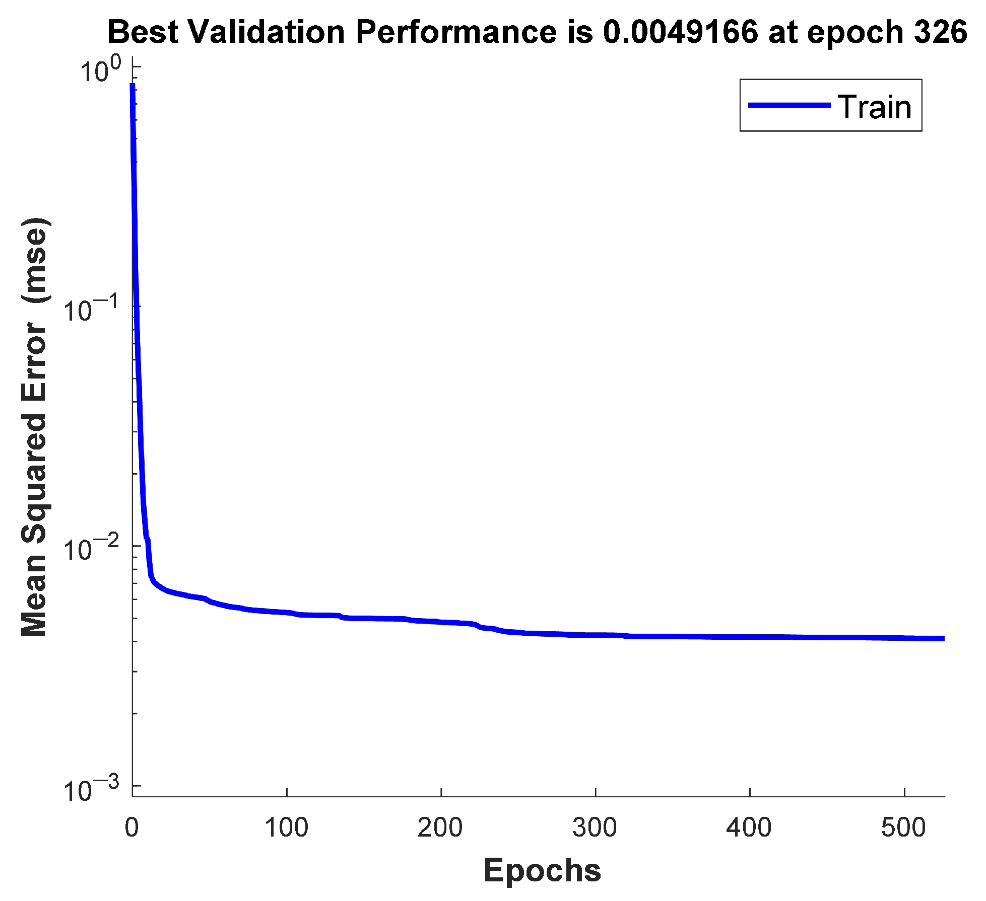
Table 1 shows critical parameters in motor simulation. Figure 4 shows the best MSE during the neural network training process. The internal parameters, including weights and biases of the neural network, are randomly initialized, and the MSE decreases as the training progresses, indicating successful convergence. After the training is completed, no further training is required during the real-time control stage of the PMSM system.

4.1. Steady-State Performance

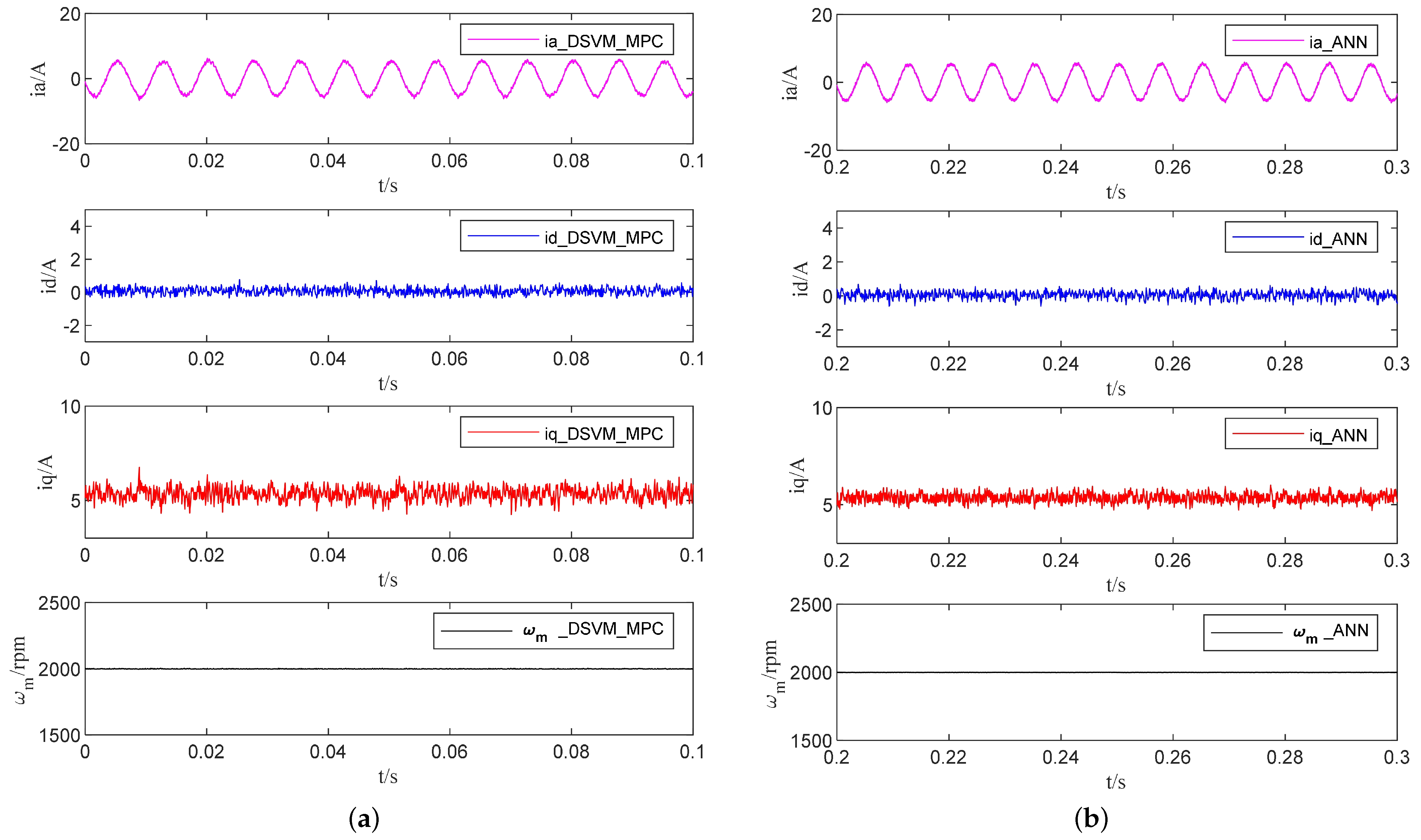
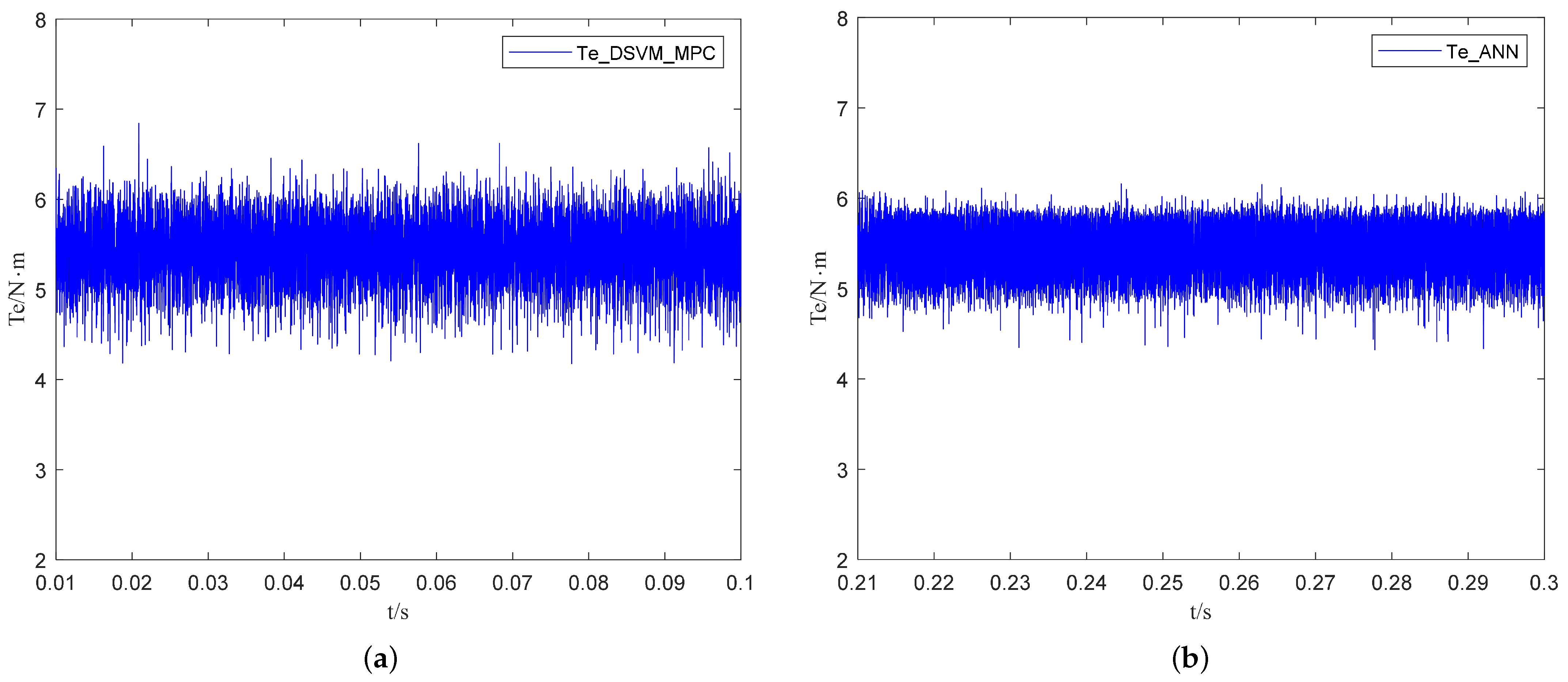
The steady-state responses of the DSVM-MPC and the DSVM-MPC-based ANN control proposed in this paper under a PMSM speed of 2000 rpm and 5 N · m load torque are shown in Figure 5. From top to bottom, the curves in the figure represent the A-phase stator current, the d-axis current, the q-axis current, and the rotor speed, respectively. It can be seen that the ANN exhibits performance equivalent to that of the DSVM-MPC, while showing smaller ripple in the q-axis current. Figure 6 shows the torque waveform under steady-state operation. The torque ripple of the DSVM-MPC-based ANN is smaller than that of the DSVM-MPC. In terms of torque ripple, the DSVM-MPC-based ANN also demonstrates a significant advantage. Additionally, it has a shorter execution time and imposes a lower computational burden than the DSVM-MPC.
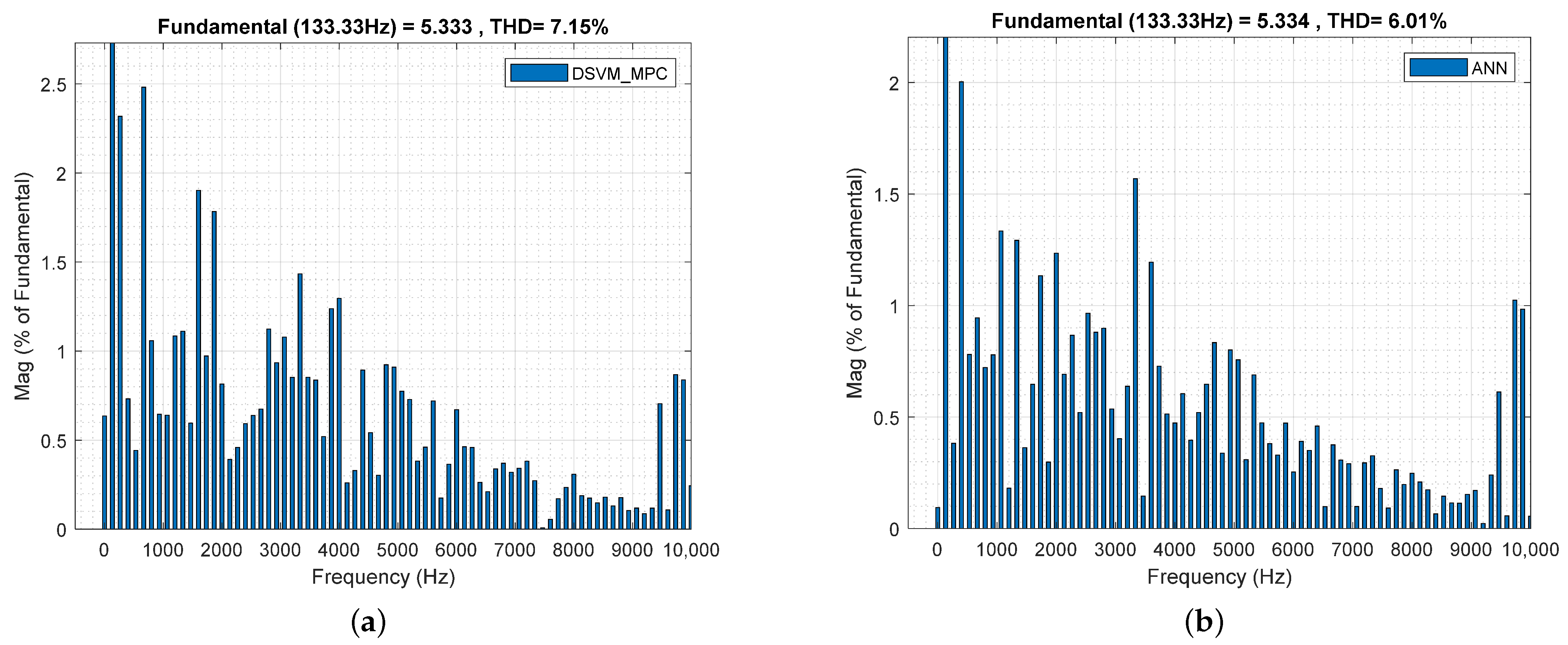
Figure 7 presents the THD analysis of the steady-state A-phase current under two different methods. It is evident that the total harmonic distortion decreases by 15.9%, from 7.15% to 6.01%, indicating that the proposed ANN yields lower current harmonics.
Table 2 presents a comparison of the current ripple rates of the two methods when the PMSM operates under steady-state conditions. For the DSVM-MPC-based ANN method, the ripple rates of the three-phase currents I a , I b , and I c are 9.83%, 10.32%, and 10.13%, respectively. Compared with the DSVM-MPC, there is a noticeable improvement. Overall, the ANN demonstrates better steady-state performance than the DSVM-MPC.

4.2. Dynamic Response

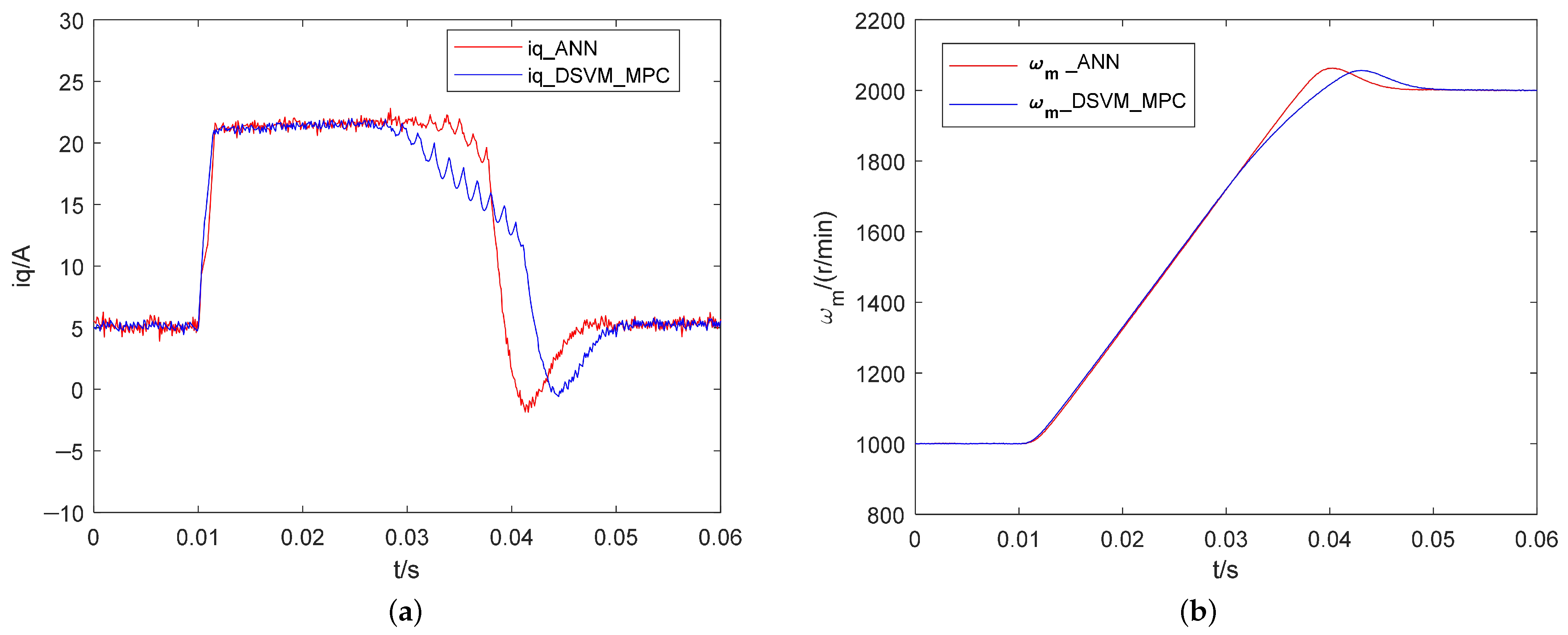
Figure 8 illustrates the responses of the two methods under a speed variation scenario. The machine operates at 1000 rpm and is then accelerated to 2000 rpm. When the q-axis current reference suddenly changes, both methods are capable of achieving very fast transient responses. By comparing the curves, it can be observed that the ANN method demonstrates superior dynamic performance. In terms of the q-axis current, the transient oscillation range of the proposed ANN method is approximately 16−22 A, whereas that of the DSVM-MPC is 10–22 A, indicating a noticeably larger oscillation range. Moreover, the DSVM-MPC-based ANN returns to the steady state more quickly. In addition, the rise time of the DSVM-MPC-based ANN is 0.0396 s, whereas that of the DSVM-MPC is 0.0435 s, indicating that the ANN achieves a noticeably faster speed response. The settling time of the proposed ANN is 0.0468 s, compared with 0.0512 s for the DSVM-MPC, showing that the system reaches stability 8.6% faster. This improvement can be attributed to the enhanced capability of the DSVM-MPC-based ANN, which, after offline training, is able to capture system nonlinearities better and thus respond more promptly to speed variations.

4.3. Performance Under Parameter Mismatches

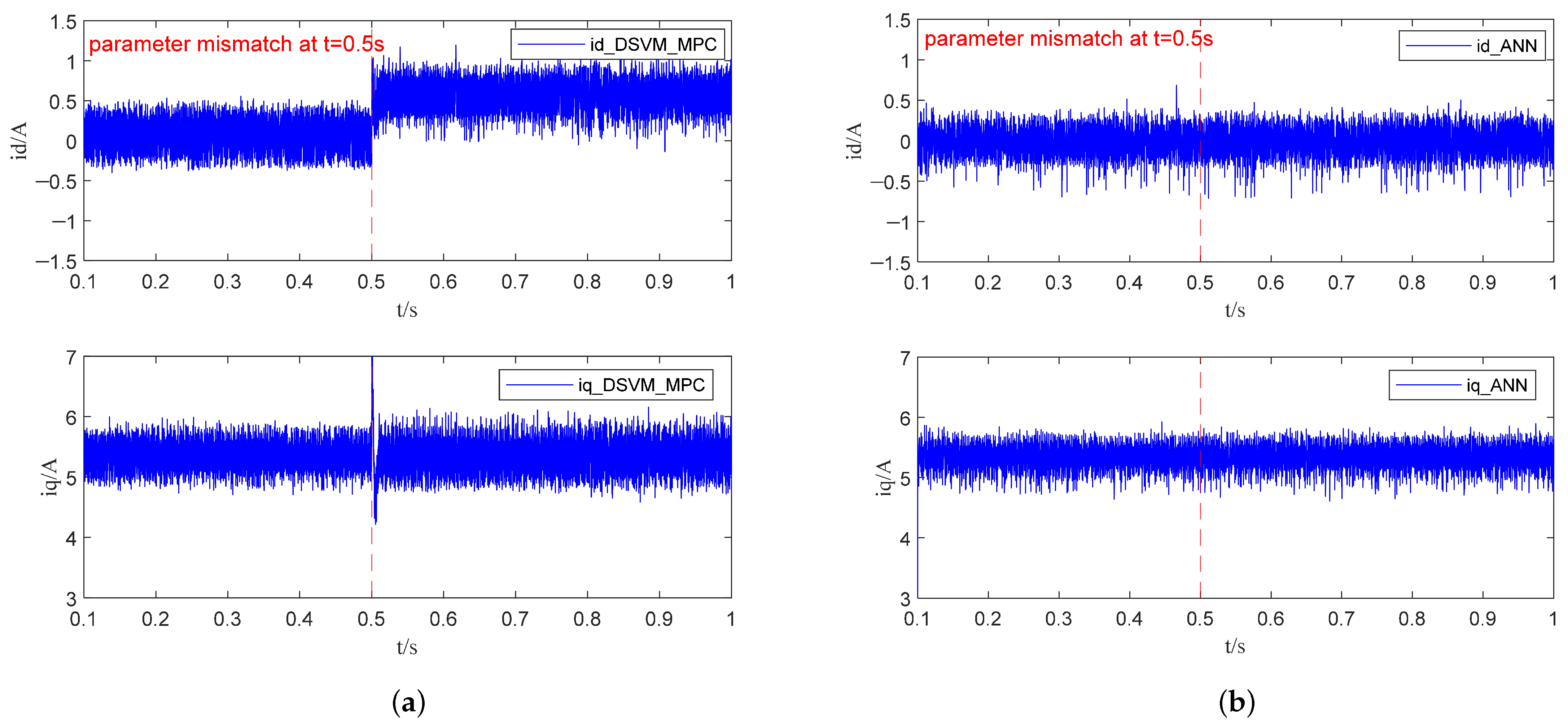
The stator winding resistance R s is highly sensitive to temperature. When the motor operates from a cold start to a steady thermal state, the winding temperature may rise by 50–100 °C, resulting in an increase in resistance of approximately 20–50%. Similarly, the inductance may also vary with temperature and the degree of magnetic circuit saturation.To verify the parameter robustness of the proposed ANN scheme, experimental tests were conducted by intentionally varying the resistance and inductance values, and the results are shown in Figure 9 and Figure 10. The resistance and inductance values were selected as the maximum possible values within their respective variation ranges. As observed in Figure 9, when the resistance and inductance parameters decrease during motor operation, the DSVM-MPC method shows a noticeable variation in i d , and the fluctuation amplitude of i q also increases. In contrast, the ANN after training is not affected by parameter variations.
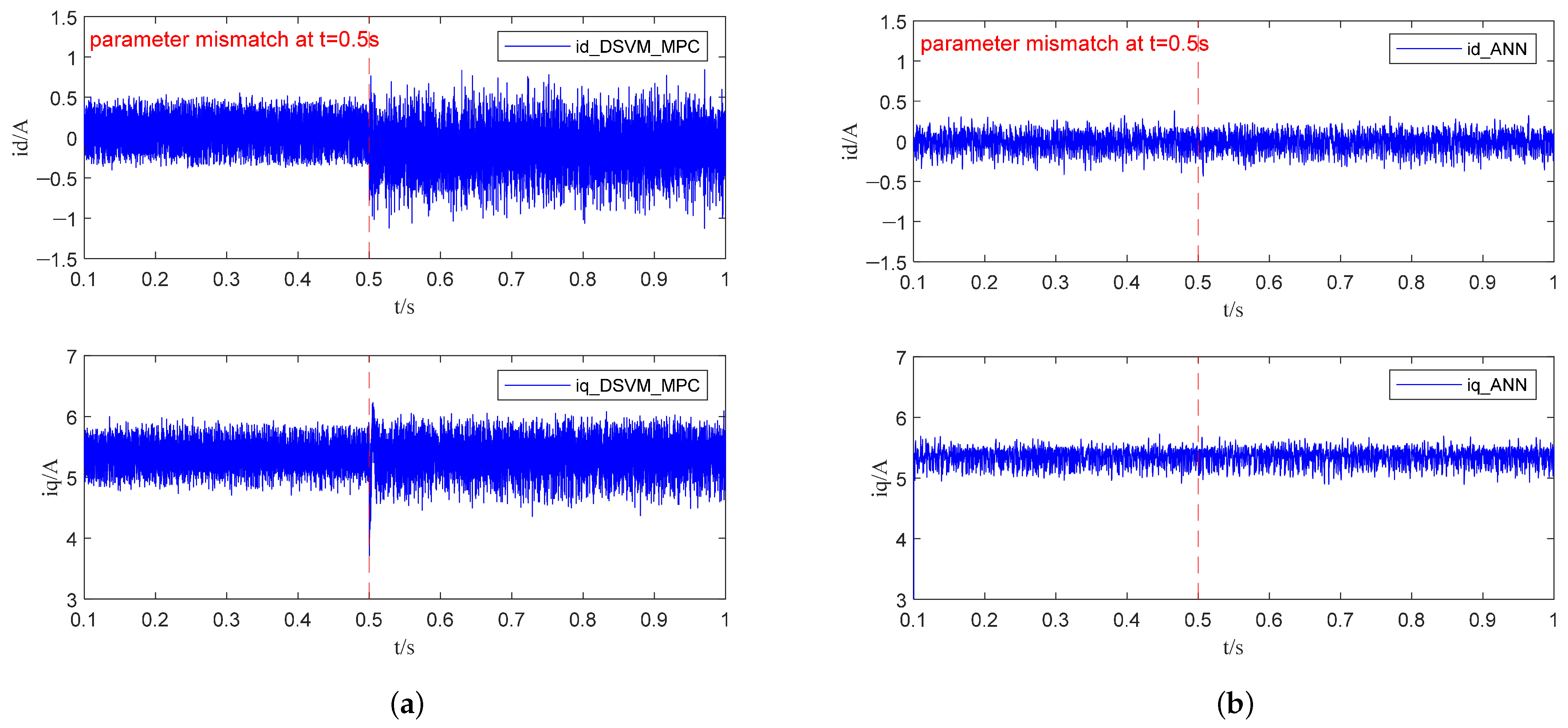
Similar results can be seen in Figure 10, where the resistance and inductance parameters are also decreased, and the q-axis current ripple remains small from the beginning.

4.4. Execution Time Analysis

The execution times of the two methods are compared, and the execution times are presented in Table 3. The execution time is obtained from the Profiler tool in the Matlab/Simulink platform. The conventional DSVM-MPC requires more time because it needs to enumerate all candidate discrete voltage vectors and perform prediction through the cost function. In contrast, the DSVM-MPC-based ANN method, after offline training, eliminates the enumeration and prediction processes, resulting in a 9.94% reduction in execution time.

5. Conclusions

This paper proposes a general and structurally designed artificial neural network (ANN) control strategy based on discrete space vector modulation model predictive control (DSVM-MPC) for permanent magnet synchronous motor (PMSM) drive systems. Unlike the conventional DSVM-MPC method that requires exhaustive enumeration of all candidate voltage vectors, the proposed control scheme introduces an ANN model trained offline using a pre-generated MPC dataset, which directly predicts and selects the optimal voltage vector. This approach significantly reduces the online computational burden while maintaining excellent control performance.
The proposed method features a clear structure and simple implementation, and its control complexity is independent of the segment number N of the discrete voltage vectors in DSVM-MPC. Moreover, the proposed ANN controller demonstrates a notable reduction in execution time compared with the original DSVM-MPC algorithm, highlighting its advantage in real-time control applications. Compared with the conventional DSVM-MPC, the proposed ANN-based control method can effectively reduce stator current harmonics and electromagnetic torque ripples under steady-state operation, achieve faster current and speed tracking during transient response, and maintain superior robustness and control performance under parameter mismatch and model uncertainty.

Author Contributions

Conceptualization, J.G. and S.H.; methodology, J.G.; software, J.G.; validation, J.G., S.H. and T.K.; formal analysis, J.G.; investigation, J.G.; resources, J.G.; data curation, J.G.; writing—original draft preparation, J.G.; writing—review and editing, J.G.; visualization, J.G.; supervision, S.H.; project administration, J.G.; funding acquisition, J.G. All authors have read and agreed to the published version of the manuscript.

Funding

This research received no external funding.

Institutional Review Board Statement

Not applicable.

Informed Consent Statement

Not applicable.

Data Availability Statement

The original contributions presented in this study are included in the article; further inquiries can be directed to the corresponding author.

Conflicts of Interest

The authors declare no conflicts of interest.

References

  1. Rodriguez, J.; Garcia, C.; Mora, A.; Flores-Bahamonde, F.; Acuna, P.; Novak, M.; Zhang, Y.; Tarisciotti, L.; Davari, S.A.; Zhang, Z.; et al. Latest Advances of Model Predictive Control in Electrical Drives—Part I: Basic Concepts and Advanced Strategies. IEEE Trans. Power Electron. 2022, 37, 3927–3942. [Google Scholar] [CrossRef]
  2. Fuentes, E.; Silva, C.A.; Kennel, R.M. MPC Implementation of a Quasi-Time-Optimal Speed Control for a PMSM Drive, With Inner Modulated-FS-MPC Torque Control. IEEE Trans. Ind. Electron. 2016, 63, 3897–3905. [Google Scholar] [CrossRef]
  3. Gao, L.; Chai, F. Model Predictive Direct Speed Control of Permanent-Magnet Synchronous Motors with Compensation for Inverter Nonlinearity and Bus Voltage Uncertainty. Energies 2023, 16, 5128. [Google Scholar] [CrossRef]
  4. Niu, F.; Wang, B.; Babel, A.S.; Li, K.; Strangas, E.G. Comparative Evaluation of Direct Torque Control Strategies for Permanent Magnet Synchronous Machines. IEEE Trans. Power Electron. 2016, 31, 1408–1424. [Google Scholar] [CrossRef]
  5. Karamanakos, P.; Liegmann, E.; Geyer, T.; Kennel, R. Model Predictive Control of Power Electronic Systems: Methods, Results, and Challenges. IEEE Open J. Ind. Appl. 2020, 1, 95–114. [Google Scholar] [CrossRef]
  6. Park, J.-H.; Kim, D.J.; Lee, K.-B. Predictive Control Algorithm Including Conduction-Mode Detection for PFC Converter. IEEE Trans. Ind. Electron. 2016, 63, 5900–5911. [Google Scholar] [CrossRef]
  7. Vazquez, S.; Rodriguez, J.; Rivera, M.; Franquelo, L.G.; Norambuena, M. Model Predictive Control for Power Converters and Drives: Advances and Trends. IEEE Trans. Ind. Electron. 2017, 64, 935–947. [Google Scholar] [CrossRef]
  8. Dragičević, T.; Novak, M. Weighting factor design in model predictive control of power electronic converters: An artificial neural network approach. IEEE Trans. Ind. Electron. 2019, 66, 8870–8880. [Google Scholar] [CrossRef]
  9. Zarei, M.E.; Nicolas, C.V.; Arribas, J.R. Improved Predictive Direct Power Control of Doubly Fed Induction Generator During Unbalanced Grid Voltage Based on Four Vectors. IEEE J. Emerg. Sel. Top. Power Electron. 2017, 5, 695–707. [Google Scholar] [CrossRef]
  10. Zhang, Z.; Hackl, C.M.; Kennel, R. Computationally efficient DMPC for three-level NPC back-to-back converters in wind turbine systems with PMSG. IEEE Trans. Power Electron. 2017, 32, 8018–8034. [Google Scholar] [CrossRef]
  11. Kwak, S.; Mun, S. Model predictive control methods to reduce common-mode voltage for three-phase voltage source inverters. IEEE Trans. Power Electron. 2015, 30, 5019–5035. [Google Scholar] [CrossRef]
  12. Zhang, Z.; Fang, H.; Gao, F.; Rodríguez, J.; Kennel, R. Multiplevector model predictive power control for grid-tied wind turbine system with enhanced steady-state control performance. IEEE Trans. Ind. Electron. 2017, 64, 6287–6298. [Google Scholar] [CrossRef]
  13. Mohd Alsofyani, I.; Lee, K.-B. Predictive Torque Control Based on Discrete Space Vector Modulation of PMSM without Flux Error-Sign and Voltage-Vector Lookup Table. Electronics 2020, 9, 1542. [Google Scholar] [CrossRef]
  14. Zhou, S.; Zhu, M.; Lin, J.; Ipoum-Ngome, P.G.; Mon-Nzongo, D.L.; Jin, T. Discrete space vector modulation and optimized switching sequence model predictive control for three-level voltage source inverters. Prot. Control Mod. Power Syst. 2023, 8, 64. [Google Scholar] [CrossRef]
  15. Boudallaa, A.; Belkhadir, A.; Chennani, M.; Belkhayat, D.; Zidani, Y.; Rhofir, K. Real-Time Implementation of Sensorless DTC-SVM Applied to 4WDEV Using the MRAS Estimator. Energies 2023, 16, 7090. [Google Scholar] [CrossRef]
  16. Yu, H.; Wang, J.; Xin, Z. Model Predictive Control for PMSM Based on Discrete Space Vector Modulation with RLS Parameter Identification. Energies 2022, 15, 4041. [Google Scholar] [CrossRef]
  17. Luo, Y.; Zhang, X.; Niu, S. A Hybrid Two-Stage Control Solution for Six-Phase PMSM Motor With Improved Performance. IEEE J. Emerg. Sel. Top. Power Electron. 2022, 10, 5435–5445. [Google Scholar] [CrossRef]
  18. Zhang, F.; Yu, S.; Wang, Y.; Jin, S.; Jovanovic, M.G. Design and Performance Comparisons of Brushless Doubly Fed Generators With Different Rotor Structures. IEEE Trans. Ind. Electron. 2019, 66, 631–640. [Google Scholar] [CrossRef]
  19. Osman, I.; Xiao, D.; Alam, K.S.; Shakib, S.M.S.I.; Akter, P.; Rahman, M.F. Discrete Space Vector Modulation-Based Model Predictive Torque Control With No Suboptimization. IEEE Trans. Ind. Electron. 2020, 67, 8164–8174. [Google Scholar] [CrossRef]
  20. Norris, G.; Ducard, G.J.J.; Onder, C. Neural Networks for Control: A Tutorial and Survey of Stability-Analysis Methods, Properties, and Discussions. In Proceedings of the 2021 International Conference on Electrical, Computer, Communications and Mechatronics Engineering (ICECCME), Mauritius, Mauritius, 7–8 October 2021; pp. 1–6. [Google Scholar] [CrossRef]
  21. Xu, H.; Lai, J.G.; Liu, J.Y.; Cao, N.; Zhao, J. Neural Network Pattern Recognition and its Application. Adv. Mater. Res. 2013, 756–759, 2438–2442. [Google Scholar] [CrossRef]
  22. Novak, M.; Dragicevic, T. Supervised imitation learning of finite-set model predictive control systems for power electronics. IEEE Trans. Ind. Electron. 2021, 68, 1717–1723. [Google Scholar] [CrossRef]
  23. Mohamed, I.S.; Rovetta, S.; Do, T.D.; Dragicević, T.; Diab, A.A.Z. A neural-network-based model predictive control of three-phase inverter with an output LC filter. IEEE Access 2019, 7, 124737–124749. [Google Scholar] [CrossRef]
  24. Al-Kaf, H.A.G.; Lee, K.-B. Low Complexity MPC-DSVPWM for Current Control of PMSM Using Neural Network Approach. IEEE Access 2022, 10, 132596–132607. [Google Scholar] [CrossRef]
  25. Guo, J.; Sun, L.; Kawaguchi, T.; Hashimoto, S. Neural Network Compensator-Based Control for Enhancing IPMSM Dynamics and Copper Loss Efficiency for Air Compressor. IEEE Access 2024, 12, 62986–62996. [Google Scholar] [CrossRef]
  26. Wang, Y.; Wang, X.; Xie, W.; Wang, F.; Dou, M.; Kennel, R.M.; Lorenz, R.D.; Gerling, D. Deadbeat model-predictive torque control with discrete space-vector modulation for pmsm drives. IEEE Trans. Ind. Electron. 2017, 64, 3537–3547. [Google Scholar] [CrossRef]
  27. Casadei, D.; Serra, G.; Tani, A. Improvement of direct torque control performance by using a discrete SVM technique. In Proceedings of the IEEE Power Electronics Specialist Conference (PESC’98), Fukuoka, Japan, 22 May 1998; Volume 2, pp. 997–1003. [Google Scholar]
  28. Casadei, D.; Serra, G.; Tani, A. Implementation of a direct control algorithm for induction motors based on discrete space vector modulation. IEEE Trans. Power Electron. 2000, 15, 769–777. [Google Scholar] [CrossRef]
  29. Keyhani, H.R.; Zolghadri, M.R.; Homaifar, A. An extended and improved discrete space vector modulation direct torque control for induction motors. In Proceedings of the IEEE Power Electronics Specialists Conference (PESC’04), Aachen, Germany, 20–25 June 2004; Volume 5, pp. 3414–3420. [Google Scholar]
  30. Ocen, D.; Romeral, L.; Ortega, J.A.; Cusido, J.; Garcia, A. Discrete Space Vector Modulation Applied on a PMSM Motor. In Proceedings of the IEEE Power Electronics Specialists Conference (PESC’06), Portoroz, Slovenia, 18–22 June 2004; pp. 1–5. [Google Scholar]
  31. Singh, B.; Goyal, D. Improved DSVM-DTC Based Current Sensorless Permanent Magnet Synchronous Motor Drive. In Proceedings of the Seventh International Conference on Power Electronics and Drive Systems (PEDS 2007), Portoroz, Slovenia, 27–30 November 2007; pp. 1354–1360. [Google Scholar]
  32. Zhang, Y.; Huangfu, Y.; Tan, B.; Quan, S.; Li, P.; Tian, C. A Virtual MPC-Based Artificial Neural Network Controller for PMSM Drives in Aircraft Electric Propulsion System. In Proceedings of the 2022 IEEE Industry Applications Society Annual Meeting (IAS), Detroit, MI, USA, 9–14 October 2022; pp. 1–6. [Google Scholar] [CrossRef]
  33. Ranganathan, A. The Levenberg-Marquardt Algorithm. 2004. Available online: http://www.ananth.in/Notes_files/lmtut.pdf (accessed on 8 June 2004).
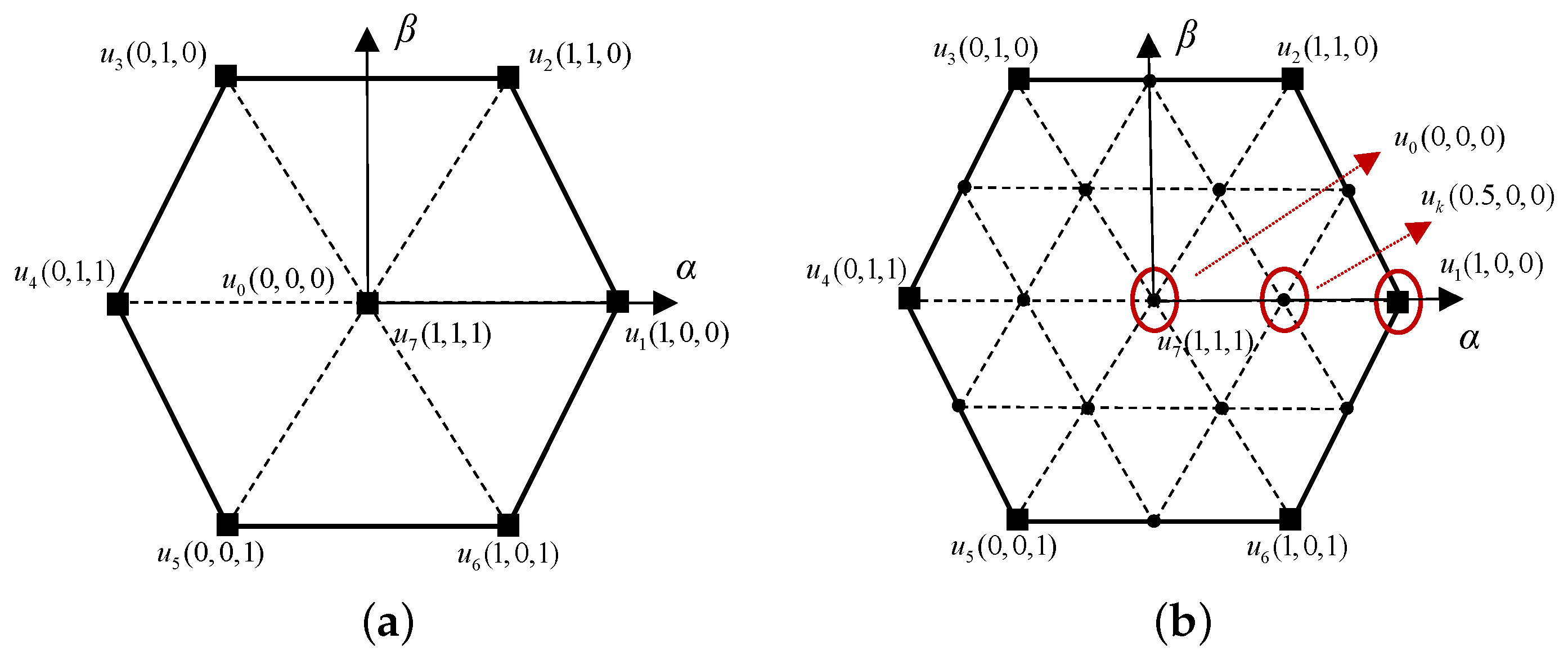
Figure 1. Voltage vectors: (a) Real vectors. (b) Virtual vectors.
Machines 13 00996 g001
Figure 3. Block diagram of the offline training process and ANN structure of the DSVM-MPC-based ANN.
Machines 13 00996 g003
Figure 4. The training loss of the ANN.
Machines 13 00996 g004
Figure 5. Steady-state response. (a) DSVM-MPC. (b) ANN.
Machines 13 00996 g005
Figure 6. Torque under steady-state response. (a) DSVM-MPC. (b) ANN.
Machines 13 00996 g006
Figure 7. Two methods of A-phase steady-state current THD. (a) DSVM-MPC. (b) ANN.
Machines 13 00996 g007
Figure 8. Dynamic response from 1000r/min to 2000r/min. (a) i q . (b) ω m .
Machines 13 00996 g008
Figure 9. Parameter mismatch with R ^ s = 0.5 R s , L ^ s = 0.5 L s . (a) DSVM-MPC. (b) ANN.
Machines 13 00996 g009
Figure 10. Parameter mismatch with R ^ s = 1.5 R s , L ^ s = 1.5 L s . (a) DSVM−MPC. (b) ANN.
Machines 13 00996 g010
Table 1. PMSM parameter data used in simulation.
ParametersValueUnit
DC bus voltage311V
Permanent magnet flux ψ f 0.1688Wb
Stator inductance L s 8.5mH
Stator copper resistance R s 0.998 Ω
Sampling period f s 10kHz
Pole pairs4/
Table 2. Current ripple rate of two methods.
CurrentDSVM-MPCANN
I a ripple rate10.58%9.83%
I b ripple rate11.03%10.32%
I c ripple rate10.89%10.13%
Table 3. Execution time comparison.
MethodsExecution Time (μs)
DSVM-MPC9.074
ANN8.172
Disclaimer/Publisher’s Note: The statements, opinions and data contained in all publications are solely those of the individual author(s) and contributor(s) and not of MDPI and/or the editor(s). MDPI and/or the editor(s) disclaim responsibility for any injury to people or property resulting from any ideas, methods, instructions or products referred to in the content.