Review

Design Methods and Practices for Centrifugal Compressor Diffusers: A Review

Romanian Research and Development Institute for Gas Turbines COMOTI, 061126 Bucharest, Romania
*
Author to whom correspondence should be addressed.
Machines 2025, 13(11), 990; https://doi.org/10.3390/machines13110990
Submission received: 8 October 2025 / Revised: 22 October 2025 / Accepted: 27 October 2025 / Published: 28 October 2025
(This article belongs to the Section Turbomachinery)

Abstract

The design of diffusers is a critical aspect of compressor performance, directly influencing pressure recovery, flow stability, and overall stage efficiency and operating range. This review paper provides an analysis of diffuser design principles, methodologies, and practical considerations in turbomachinery applications. The importance of diffusers in compressors is discussed, and the main types of diffusers are presented, highlighting, for each type of diffuser, their aerodynamic characteristics and operational advantages. Traditional empirical correlations and analytical models for diffuser geometry generation are reviewed, emphasizing their role in guiding preliminary design decisions. The integration of one-dimensional (1D) performance analysis methods with computational fluid dynamics (CFD) simulations is also discussed, illustrating how these approaches improve performance prediction and optimization accuracy. Design constraints are analyzed alongside performance trade-offs, highlighting the need to balance efficiency and stability. Overall, this review synthesizes existing knowledge on diffuser design in compressors, providing a structured framework for engineers and researchers to understand the key factors affecting performance and guiding the development of efficient, reliable diffuser configurations for real-world turbomachinery applications.

1. Introduction

The aerodynamic configuration and sizing of compact radial compressor diffusers play a critical role in determining the overall efficiency, stability, and performance of turbomachinery systems. As compressors are miniaturized for applications such as aerospace propulsion, automotive turbocharging, and compact energy systems, the design of the diffuser becomes increasingly challenging due to space constraints, high flow turning angles, and potential losses due to flow separation and secondary flows. A well-designed diffuser must effectively decelerate and recover static pressure from the high-speed flow exiting the impeller, while minimizing total pressure losses and maintaining flow uniformity.
Aerodynamic performance is especially critical in gas turbine diffusers, where the incoming flow typically features high swirl and significant non-uniformity from the impeller exit. This demands precise diffuser shaping to stabilize the flow and prevent separation, particularly under high relative Mach numbers (0.7–1.2) [1]. Managing deceleration in these conditions is essential for preserving performance, as pressure recovery within the diffuser directly influences the compressor pressure ratio and overall thermal efficiency. Any inefficiencies here reduce the pressure available for combustion, impacting the engine’s entire thermodynamic cycle. To avoid flow separation, wall diffusion angles are generally kept within 7–10° (14–20° included angle) [2], although compact designs may push these limits, requiring advanced geometries and CFD-driven optimization.
The choice between vaned and vaneless diffusers further influences this balance. Vaned diffusers, with their ability to provide higher pressure recovery in a shorter axial distance, are advantageous for compact configurations [3,4]. However, their performance is highly sensitive to the angle at which flow exits the impeller [5,6], which can vary under off-design conditions. In contrast, vaneless diffusers offer greater tolerance to incidence angle variation and produce smoother pressure gradients, reducing the risk of flow separation [7]. The trade-off lies in their increased radial dimensions and longer flow path, which can be detrimental in space-limited environments.
These geometric constraints underscore the importance of diffuser sizing, particularly in achieving the required area ratio without expanding the radial footprint. Parameters such as the hub-to-tip/hub-to-shroud width, hub and shroud surfaces, tip leakage behavior, and secondary flow development [8]. Proper optimization of these aspects ensures stable, three-dimensional flow and supports the overall aerodynamic integrity of the compressor stage—especially in high-speed, high-performance applications [9]. In addition to aerodynamic considerations, the diffuser must deliver well-conditioned flow to the combustor or plenum. This means minimizing residual swirl and achieving uniform velocity profiles tangent to the meridional surface at the diffuser exit, which is critical for combustion stability and efficiency [10]. To meet these requirements, features such as deswirl vanes or flow straighteners are often incorporated, particularly in close-coupled combustor designs.
In compact architectures, thermal expansion must be carefully managed to prevent mechanical interference or leakage at component interfaces. Mechanical vibrations are a significant challenge in diffuser design, particularly for vaned diffusers, which are more susceptible to dynamic excitation from upstream blade-passing frequencies [11]. These interactions can lead to high-cycle fatigue (HCF) or even resonance, especially if the natural frequency of the diffuser vanes coincides with the excitation frequency from the impeller blades [12]. Modern manufacturing technologies—especially additive manufacturing—offer new possibilities for addressing these design challenges. Complex geometries that improve aerodynamic performance, such as contoured walls or integrated flow-conditioning features, can now be fabricated more easily. However, these advantages must be weighed against considerations of manufacturability, cost, and long-term reliability. In some cases, simpler geometries may be intentionally selected to enhance robustness and reduce production complexity, even at the cost of marginal efficiency losses. Finally, the diffuser must perform reliably across a wide operating envelope. Gas turbines often operate under variable loads and transient conditions, meaning that flow rates and inlet angles can deviate significantly from the design point. Diffuser designs must therefore maintain stable performance under off-design conditions to avoid flow separation or compressor surge, preserving overall engine operability, surge and chock margin [13].
Taken together, these aerodynamic, geometric, thermal, and structural factors make diffuser design a critical—and complex—component of compact turbomachinery development. This paper provides a critical review of the core design principles, performance constraints, and modern optimization strategies applied in compact radial compressor diffusers. Emphasis is placed on comparing traditional empirical approaches with advanced computational and experimental techniques, highlighting key trade-offs and identifying areas for future research and innovation.

2. Fundamentals of Compressor Diffusers

2.1. Types of Diffusers

The primary role of a diffuser in a centrifugal compressor is to convert the high kinetic energy imparted by the impeller into increased static pressure by gradually slowing down the flow. This deceleration allows for efficient energy conversion while minimizing total pressure losses. A vaned diffuser operates on the same basic principle as a conventional duct diffuser but incorporates fixed blades (vanes) to better guide the flow. These vanes improve pressure recovery by directing flow, reducing separation, and enhancing diffusion efficiency—particularly important in high-speed or compact compressor designs. Essentially, the diffuser is a stationary passage with an expanding cross-sectional area (Figure 1) that acts as a non-rotating channel, slowing the impeller’s high-velocity flow and converting kinetic energy into static pressure, which is critical for overall compressor performance [14].
The corresponding Aspect Ratio (AS) of the 2D diffuser is:
A S = A 2 A 1 = 1 + 2 L b t a n θ
and that of the conical diffuser is:
A S c o n i c a l = A 1 A 2 = 1 + 2 L d t a n θ 2
L is the axial length of the diffuser, b is the channel width for the two-dimensional diffuser, d is the inlet diameter of the conical diffuser and θ is the divergence angle of the diffuser.
Next, various applications of different types of diffusers that can be developed for compressors are presented, each designed to optimize flow characteristics and performance based on specific operational requirements.

2.1.1. Vaneless Diffusers

The vaneless diffuser, a key component in centrifugal compressors, is characterized by its simple geometry—parallel or nearly parallel walls forming a radial annular passage from the impeller outlet to the diffuser exit (Figure 2).
Vaneless diffusers are generally classified into three types based on the ratio of diffuser outlet width to impeller outlet width: parallel-wall, convergent, and expansion types. Expansion-type designs, due to their large cross-sectional area, are prone to reversed pressure gradients, backflow, and secondary flows—factors that compromise efficiency and limit their practical application [15]. Even though vaneless diffusers are shock-free and geometrically simple, they can suffer from flow instabilities and performance losses if not carefully designed, particularly in expansion configurations [16].
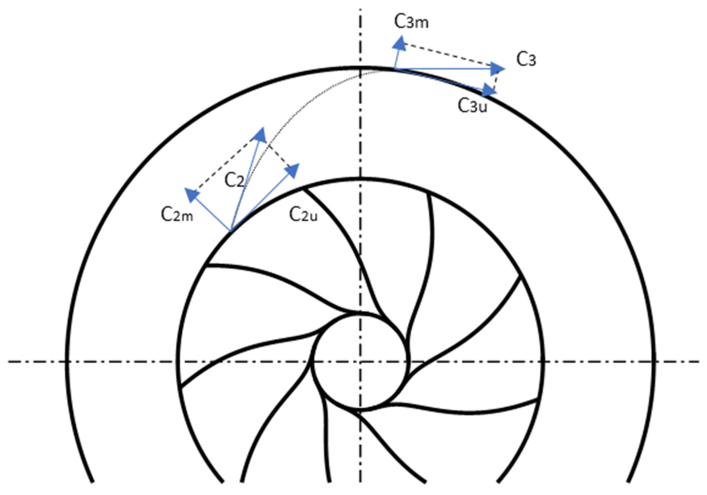
Figure 2. Elementary view of velocity triangles in vaneless diffusers (redrawn based on [17]). Zone 2 is the impeller outlet, zone 3 is the diffuser discharge.
Machines 13 00990 g002
Experimental evaluations of various vaneless diffuser geometries highlight the impact of shape on performance. In the study conducted by Ludtke et al. [18], four vaneless diffuser configurations—wide parallel-walled, narrow parallel-walled, constant-area tapered, and reduced-area tapered—were experimentally investigated in the first stage of a four-stage industrial centrifugal compressor, operating at tip-speed Mach numbers between 0.94 and 1.07. Their results indicated that narrowing and tapering the diffuser improved turn-down capability, although the narrowest geometries led to a notable decrease in efficiency. The wide parallel-walled diffuser achieved the highest efficiency but exhibited a limited surge margin. Among the tested configurations, the constant-area tapered diffuser offered the best compromise, enhancing the surge margin by approximately 10% while maintaining nearly the same efficiency. In a subsequent investigation [19], five vaneless diffusers with wall shapes ranging from mildly divergent to strongly convergent were tested. The findings showed that convergence produced a stabilizing (negative) slope in the pressure rise curve. Convergent designs yielded better static pressure recovery at intermediate flow rates and lower-than-expected losses at high flow rates, attributed to improved flow uniformity at the diffuser outlet.
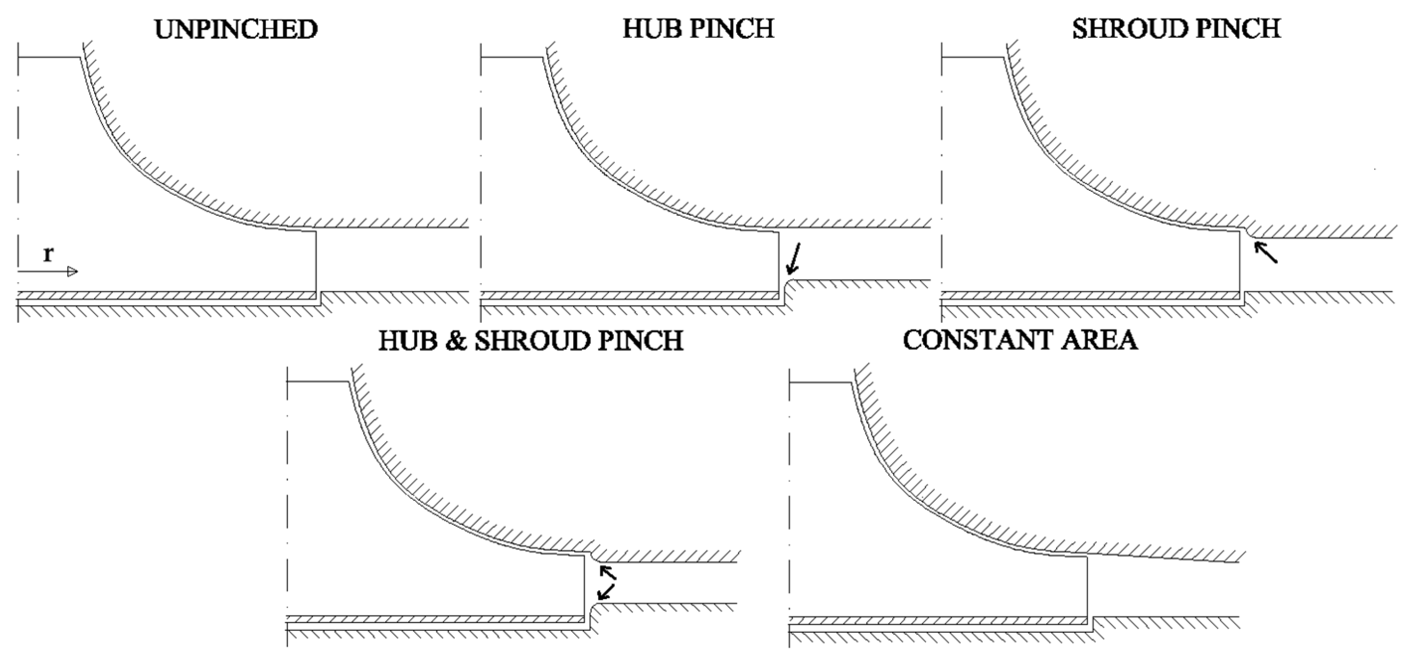
Another geometrical method for improving diffuser performance is the shroud-pinched configuration (Figure 3). This design has been shown to significantly enhance isentropic efficiency and reduce secondary flows under low mass flow conditions. It achieves this by aligning more effectively with the high-velocity flow near the impeller tip. This type of vaneless diffuser inlet has been previously presented (but not specifically named) in the preliminary design stages of a centrifugal compressor in [20]. The algorithm states that the vaneless diffuser shroud surface is not required to be tangent to the impeller shroud contour at impeller tip.
The experimental studies in [21,22] investigated the effects of pinching the vaneless diffuser in centrifugal compressors using multiple diffuser heights and pinch configurations applied to the hub, shroud, or both. Both studies confirmed that diffuser pinching improves overall compressor performance by increasing isentropic efficiency and pressure ratio, primarily through enhanced rotor and diffuser efficiency, although volute or exit cone efficiency slightly decreased. Pinching at the shroud wall was found to be most effective, as it made the flow more radial and increased velocity in regions with secondary rotor flow. These findings highlight that the simple, wide-operating-range vaneless diffuser benefits significantly from geometry modifications like pinching to optimize the conversion of rotor exit velocity into static pressure and improve compressor stage performance.
Figure 3. Vaneless diffuser inlet constructions [23].
Machines 13 00990 g003
In contrast, the hub-pinched design offers improvements primarily near the design point and near choking condition but is less effective than shroud pinching at off-design conditions [24]. When both hub and shroud are symmetrically pinched, the design delivers balanced improvements across a wider range of flow rates, though it may not optimize performance at any single operating point [25]. The constant area vaneless diffuser has demonstrated improvements in surge margin without significantly compromising efficiency compared to wide, unpinched diffusers [26]. While unpinched (parallel wall) diffusers offer design simplicity and acceptable baseline performance, it tends to exhibit lower surge margins and less stable flow behavior than their pinched or tapered counterparts [27,28]. This configuration is typically followed by a volute or collector that guides flow to a unidirectional outlet. A small inlet pinch is often included to stabilize the entering flow. One of the main advantages of vaneless diffusers is their ability to operate without strong shock losses, even at supersonic inlet velocities, making them especially useful in designs where a vaneless section precedes vaned diffusers to slow the flow to subsonic speeds [29].
In terms of optimization of diffuser design, advanced design approaches like the Direct Method for Optimization (DMO) have been employed to improve diffuser performance. DMO, which uses Reynolds-Averaged Navier–Stokes (RANS) simulations to optimize a nonlinear objective function combining pressure rise and energy loss, offers a more direct alternative to traditional inverse methods. Applied to a three-dimensional vaneless diffuser in a shipboard air-conditioning compressor, this method produced a novel geometry with its minimum width positioned beyond the conventional pinch point. This layout allowed efficient pressure recovery and demonstrated superior performance both at design and off-design conditions, validated through experiments [30]. Other geometric studies focused on reducing stage diameter without compromising performance. In one such case, two stators of a multistage centrifugal compressor were redesigned with 8% and 14% reductions in outer diameter by decreasing the vaneless diffuser’s diffusion ratio, while keeping impeller exit diameter and axial length constant. A 1.5-stage rig with a pseudo-stage was used to replicate multistage effects, and the experimental data helped calibrate 1D and 3D CFD tools. Optimization via design-of-experiments methodology ensured that spanwise flow profiles remained within acceptable bounds. Final tests confirmed that compact diffuser designs maintained both efficiency and operating range [31].
Jaatinen et al. [32] demonstrated that reducing diffuser width, especially through shroud-side narrowing, improves centrifugal compressor efficiency at low and design speeds. However, it can decrease pressure ratio at high speeds. A width ratio of 0.854 was found to perform best, as it also reduces the impeller work input. Govardhan et al. [33] showed that, among modifications to a Forced Rotating Vaneless Diffuser, blade cutbacks lowered performance, while a 30% shroud extension significantly enhanced static pressure rise, reduced losses, and expanded the operating range compared to stationary vaned diffusers. Complementing these findings, study [34] revealed that larger tip clearances in vaneless diffusers increase secondary flow near the shroud. This leads to higher aerodynamic losses, decreased efficiency, and greater circumferential flow asymmetry under off-design conditions.
The stability of centrifugal compressors with vaneless diffusers has also been a focus of recent numerical studies. At low mass flow rates, the diffuser becomes the limiting component, with stall patterns shifting into the inducer and stabilizing impeller flow. Instability is primarily driven by the inlet-flow angle, which can be used to estimate the stability limit as a function of mass flow. This relationship must be calibrated for each compressor using steady single-passage RANS simulations at high mass flow rates, providing an efficient and practical tool for predicting stability limits [35]. The design of the vaneless gap—the region between the impeller outlet and diffuser inlet—is critical to centrifugal compressor and pump performance. Aungier [20] recommends a radius ratio between 1.06 and 1.12 to strike a balance between providing adequate space for flow mixing and minimizing aerodynamic losses. The lower limit of this range allows the distorted impeller exit flow and wake to recover before encountering the diffuser vanes [36], while the upper limit prevents excessive losses due to overextended vaneless space. Proper sizing of this gap also helps reduce high impeller exit Mach numbers, delaying the onset of choking in the diffuser [37].
Murray [38] further emphasized that both the number of diffuser vanes and the vaneless gap size significantly affect impeller performance. He proposed the gap-to-vane-pitch ratio as a key design parameter, showing through simulations that impeller performance varies nonlinearly with this ratio—indicating an optimal point for maximizing efficiency and pressure ratio. Complementing these findings, a numerical study on subsonic mixed-flow compressors with a crossover diffuser evaluated VGR (vaneless gap ratio) values from 1.03 to 1.12 across three configurations. The results showed that increasing VGR consistently shifts the performance curve rightward, enhancing the operating range by improving choke margin more than it reduces stall margin. A revised VGR formula was proposed for mixed-flow configurations, and within the range of 1.04–1.12, design-point efficiency and pressure ratio variations remained within 1.5% and 3%, respectively [39]. Another investigation into high-pressure centrifugal compressors examined six radial gap ratios (1.04–1.14) at five rotational speeds. It found that for Mu < 1.0, smaller radial gaps enhanced diffuser performance with little effect on stage efficiency. However, at Mu ≥ 1.0, larger gaps mitigated shock formation at the diffuser inlet, and a radial gap ratio of 1.08 offered the best performance compromise, improving stability and efficiency while slightly reducing impeller performance [40].
In a related study on centrifugal pumps, 3D RANS simulations and a leakage loss model were used to assess side-gap flow effects between the impeller and diffuser. Variations in radial clearances (0.5 mm, 1.0 mm, 1.5 mm) revealed that the direction of leakage flow—whether inflow or outflow—significantly alters performance and internal flow structures. These findings underscore the need to carefully manage side-gap leakage in pump designs to optimize efficiency and reduce performance losses [41].
Table 1 presents a summary of vaneless diffuser configurations and performance characteristics.

2.1.2. Vaned Diffusers

Vaned diffusers are essential elements of centrifugal compressors, responsible for decelerating the flow and recovering static pressure. Based on vane arrangement and geometry, they are typically divided into cascade diffusers and channel diffusers.
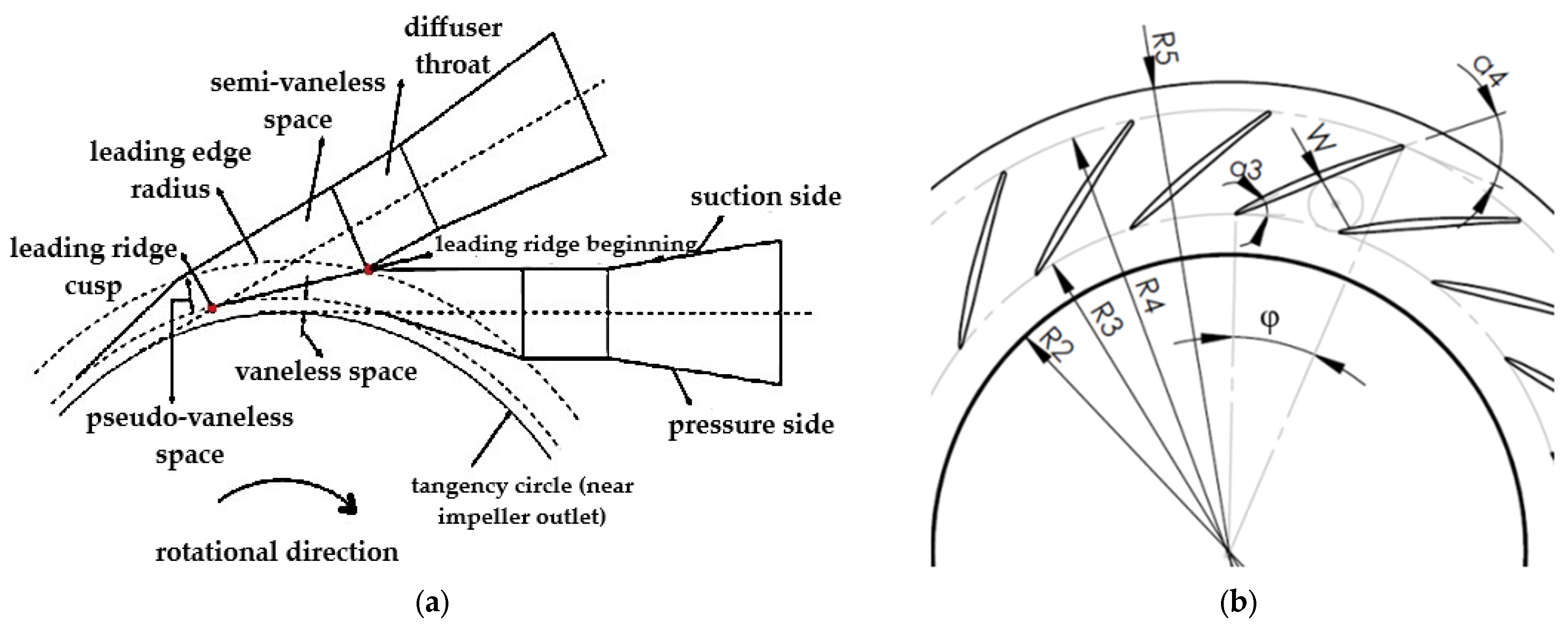
  • Cascade diffusers employ thin, airfoil-shaped vanes to control flow angles with precision. They are particularly effective in subsonic regimes, where careful flow redirection is required. As shown in Figure 4a, cascade diffusers generally consist of one or more rows of airfoil vanes that redirect the flow from angle α3 to α4.
  • Channel diffusers, in contrast, are designed to accommodate large area changes and higher Mach number flows. They frequently incorporate semi-vaneless logarithmic spiral profiles, making them well suited to compressible and supersonic regimes. Figure 4b illustrates such designs, which can manage substantial density variations with increasing radius.
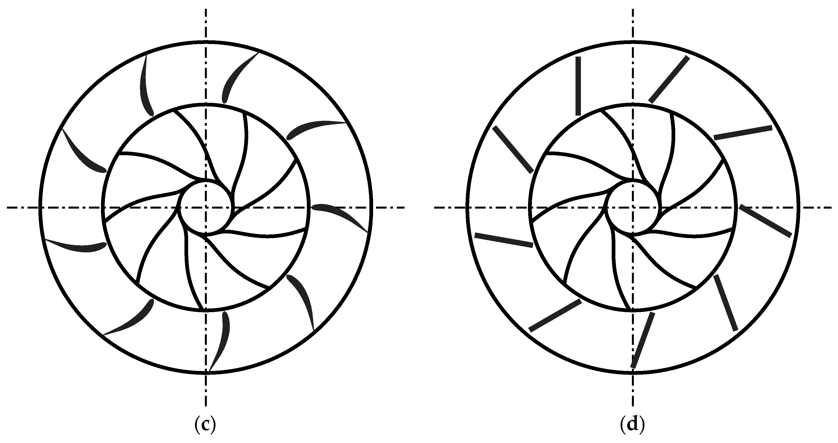
  • Low-Solidity Vaned Diffusers (LSVDs), illustrated in Figure 4c, are usually a crossover between vaned and vaneless diffusers. They have geometrical properties similar to cascade diffusers, except that the blade length and number of blades are smaller than those of conventional vaned diffusers.
  • LSVDs with flat vanes are depicted in Figure 4d.
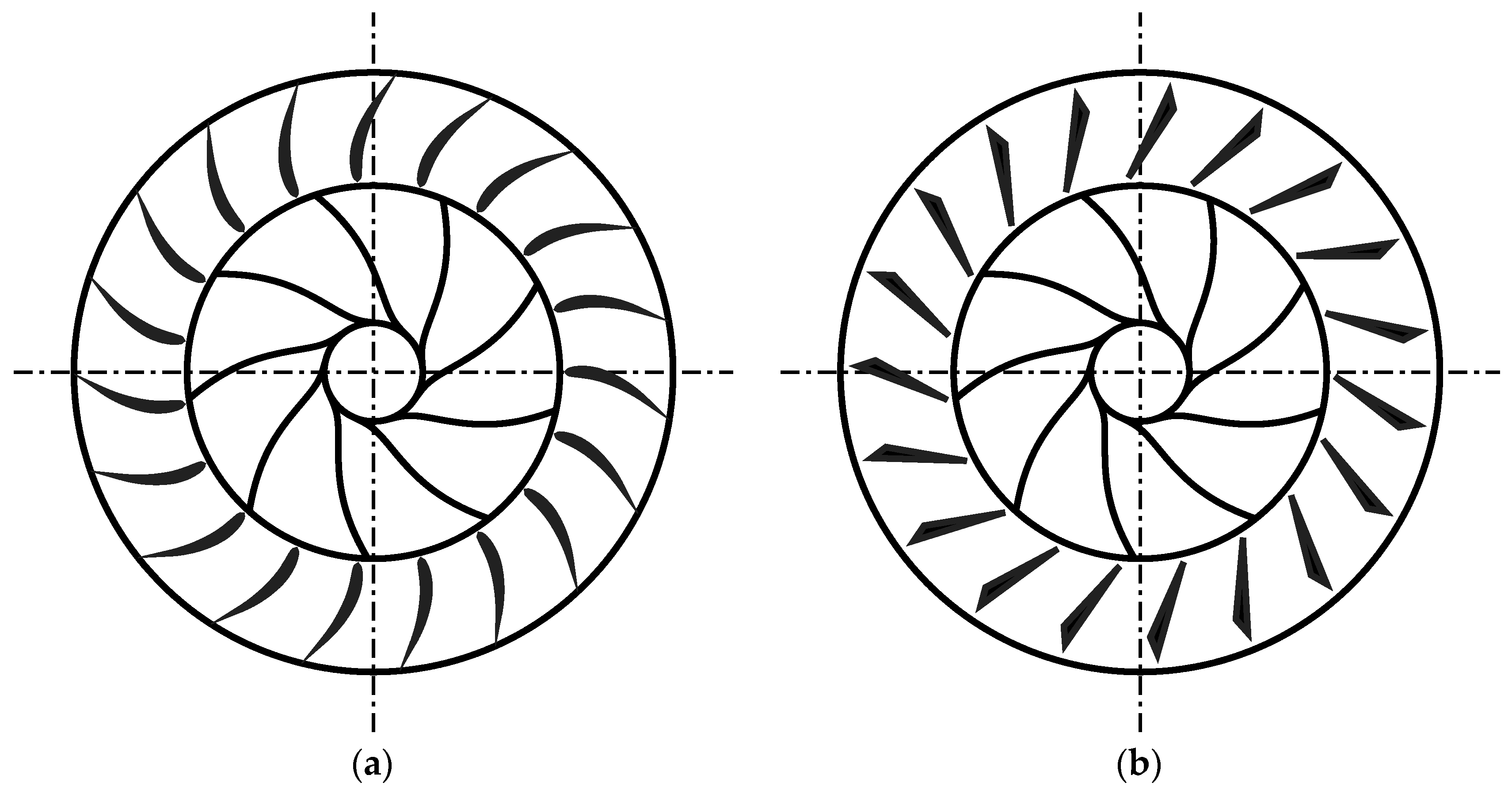
Figure 4. Different types of vaned diffuser: (a) cascade; (b) channel; (c) LSVD; (d) LSVD with flat vanes (redrawn based on [24]).
Machines 13 00990 g004aMachines 13 00990 g004b
Early experimental investigations established fundamental design principles for vaned diffusers. In a 1987 study of straight wedge (channel) diffusers, divergence angles () ranging from 4° to 14° were examined. An optimal efficiency was identified at 12°, while larger divergence angles reduced the stable operating range [42]. Notably, diffusers with and without sidewall divergence exhibited similar performance when the area ratio remained constant. A separate comparison between a straight-channel diffuser and a discrete-passage type highlighted performance differences under varying inlet conditions. The straight-channel diffuser, equipped with 30 vanes, achieved higher maximum pressure recovery (0.78) than the discrete-passage diffuser (0.70). However, both suffered from rotating stall at fixed flow angles, limiting their range of stable operation [43].
The conventional geometry of channel diffusers typically consists of an initial section shaped as a logarithmic spiral along one of the vane surfaces, followed by a main section with straight walls (Figure 5a). This design facilitates smooth deceleration of the high-speed flow exiting the impeller, promoting pressure recovery while minimizing total pressure losses. In addition to this traditional design, channel diffusers with wedge-shaped vanes are widely used (Figure 5b), as they can better control the flow expansion and reduce the risk of flow separation, particularly at higher flow rates.
To aid diffuser design, Kang et al. [45] developed a hybrid performance prediction methodology that combines one-dimensional compressible core-flow calculations, boundary-layer modeling, and empirical correlations. The diffuser was divided into four subregions: vaneless space, semi-vaneless space, main channel, and exit. Experimental validation confirmed that the method can accurately capture non-uniform pressure fields generated by impeller–diffuser interactions across diverse operating conditions.
From a stability perspective, advanced numerical studies have compared vaneless and island-vane diffusers near surge. Results demonstrated that vaned configurations more effectively suppress backflow-induced instabilities [46]. While vaneless designs showed large-scale, continuous low-velocity backflow with gradual pressure decay, vaned diffusers exhibited localized stall and sharper pressure fluctuations. Complementary experimental analyses on diffuser vane impacts in high-pressure-ratio compressors, particularly for aero-engine applications, further confirm that vaned diffusers can mitigate rotating stall and delay surge onset, enhancing the compressor’s dynamic stability. However, their influence diminishes at lower shaft speeds, highlighting the importance of speed-dependent vane design strategies [47]. Aerodynamic optimization study focused on vaned diffusers under subsonic to supersonic inlet conditions. By adjusting blade geometry and endwall contours, the optimized diffusers achieved significant efficiency gains, along with improvements in pressure ratio and surge margin across all Mach regimes [48].
Experimental studies [49,50] have also confirmed the impact of the vane install angle on compressor stability. These studies highlight the regimes (flow coefficient and impeller peripheral tangential speed) where impeller rotating stall, impeller recirculation and surge occur.
Introduced in the 1990s, tandem-bladed impellers emerged as a promising solution to extend operating stability without resorting to active control systems [51]. A tandem configuration consists of two closely spaced blade rows with adjustable circumferential offsets. Early investigations attributed performance improvements to blade clocking effects rather than slot geometry [52]. Subsequent studies emphasized the importance of unsteady simulations in capturing tandem-specific flow interactions [53]. Even small changes in the front blade setting angle (≈2°) produced notable effects, shifting surge margins by 1.5–4.2% and influencing efficiency trends through altered incidence and flow separation [54].
Comparative analyses of Traditional Vaned Diffusers (TVDs), Low-Solidity Diffusers (LSDs), and Partial-Height Vanes (PVDs) highlighted the significant role of geometry. TVDs provided the highest peak efficiency, vaneless diffusers the widest flow range, and LSDs an effective balance. PVDs showed additional potential when vane height and placement were optimized, particularly near the shroud [55].
In turbocharger applications, tandem-bladed impellers delivered up to a 25% increase in operating range [56]. These gains were linked to reductions in blade thickness and increases in vane count, while axial spacing and clocking effects were comparatively minor. Design of Experiments (DOE) optimization further revealed that rear-row stagger angle exerted the greatest influence on efficiency and pressure ratio [57].
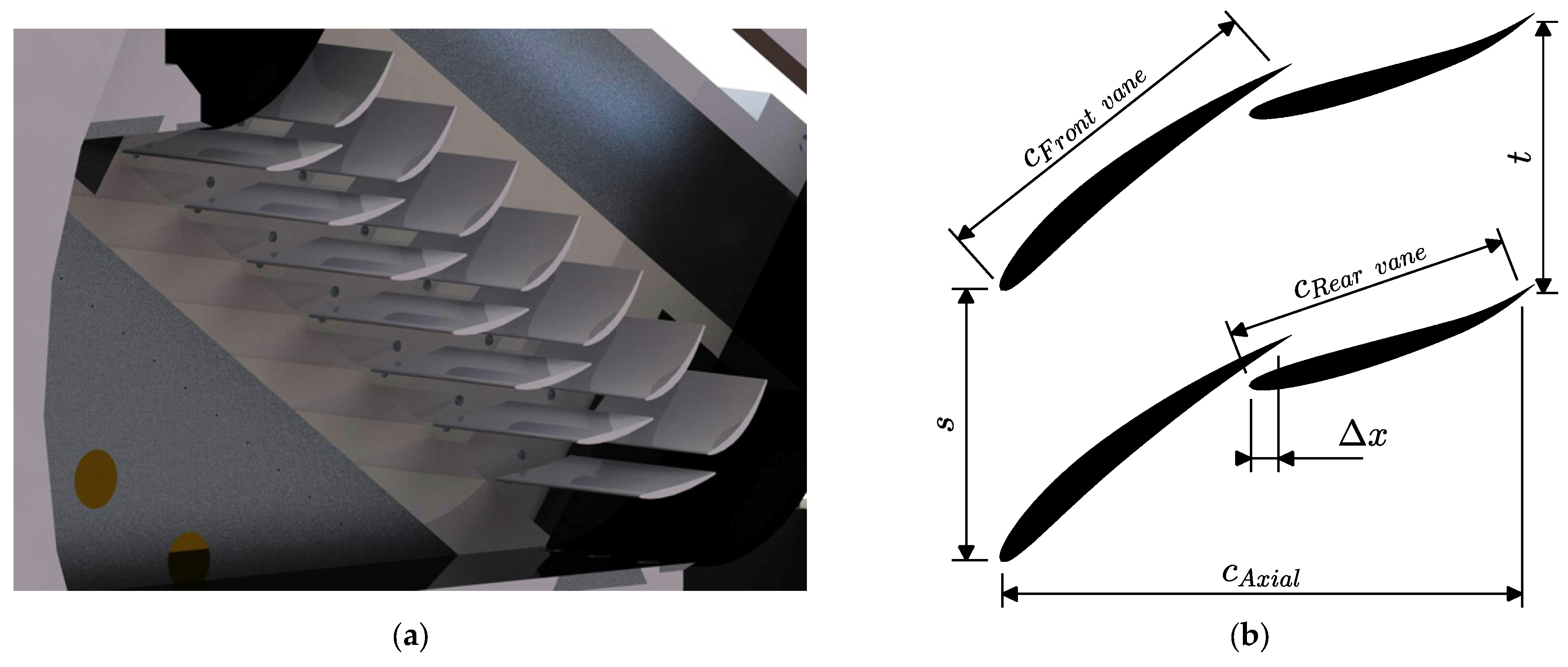
Stability improvements through passive flow control were also achieved using tandem impellers. By raising the static pressure at the inducer trailing edge, these configurations suppressed leading-edge separation and weakened radial low-momentum flow, resulting in a 16.7% extension of the stable operating range. These effects were further influenced by the blade clocking fraction, which affected the inducer pressure field and overall flow behavior [58]. Innovations such as adding small gaps to tandem diffuser blades (Figure 6)—despite their typical association with energy loss—proved beneficial in broadening the compressor’s surge and stability margins, with a 2.5% tip gap yielding substantial gains and only minimal efficiency penalties. Gaps under 5% of blade height, particularly on the shroud side, were most effective, contributing to lower Mach numbers in diffuser channels [59]. Similarly, a study on tandem cascade diffuser geometry found that a total bending angle of 10° between blade rows minimized pressure losses and flow separation, improving stage efficiency by 6% and pressure ratio by 3.5% compared to conventional diffusers [60].
Lastly, studies examining secondary flow effects, such as leakage from shrouded stator cavities, revealed that these flows degrade compressor performance by increasing pressure and energy losses, particularly at reduced operating speeds. The radial momentum of leakage flow was found to be strongly correlated with loss generation, while circumferential momentum had more complex, sometimes contradictory effects on performance [61]. Altogether, this body of research demonstrates a clear trajectory toward more refined, efficient, and stable centrifugal compressor systems through the innovative application and optimization of tandem-blade and diffuser configurations.
Low-Solidity Vaned Diffusers (LSVDs) were developed to combine the benefits of vaneless and fully vaned designs, Figure 7. By reducing vane number or vane length, LSVDs achieve broader operating ranges while maintaining good pressure recovery. Their performance is governed by parameters such as vane inlet radius, vane inlet angle, solidity, turning angle, and vane count. Comparative studies confirm that LSVDs outperform vaneless diffusers in pressure recovery while retaining wider flow ranges than fully vaned designs [62]. Incidence angle is a critical factor: negative incidence angles enhance efficiency and flow range, whereas positive incidence angles reduce both [63].
Figure 6. Compressor stage with tandem blades: (a) 3D view [64]; (b) 2D schematic representation (c—chord length; s—pitch; Δx—distance between front vane TE and LE of rear vane; t—distance between TE of rear vanes).
Machines 13 00990 g006
Figure 7. Layout of the LSVD flow path [23].
Machines 13 00990 g007
Both numerical and experimental studies confirm that LSVDs strike an effective balance between efficiency and flow range when compared to traditional vaned, vaneless, and partial-height vane diffusers. Strategic design choices—such as increasing vane height or placing half-height vanes on the shroud side—have been shown to promote more uniform flow and enhance stage efficiency [65]. Additionally, modifications like pinching of diffuser hub and shroud walls can yield up to 2–3% gains in isentropic efficiency, with hub-only pinching proving most effective [66].
CFD studies have shown that reducing diffuser solidity—typically by lowering the number of vanes—can enhance centrifugal compressor efficiency and broaden the operating range, although it may also lead to increased turbulence and reduced flow uniformity [67]. This is particularly important for fuel cell vehicle compressors, which often operate near the surge line and therefore require enhanced stability. To address this, four diffuser configurations—vaneless (VLD), low solidity vaned (LSVD), hub-side half vaned (HVD), and shroud-side half vaned (SVD)—were evaluated through numerical simulations. Results showed that LSVD, HVD, and SVD provided better performance than VLD under design, surge, and choke conditions, with HVD achieving a 15.53% lower surge flow rate than LSVD. The improved stability of half vaned diffusers was attributed to the migration of tip leakage vortices toward the vane mounting side, which replenishes low-momentum regions. Optimal vane placement was found to depend on the impeller exit flow field, particularly aligning with wake zones of low meridional velocity and stagnation pressure [68].
For high-demand applications such as Compressed Air Energy Storage (CAES), integrating LSVD designs within advanced aerodynamic optimization frameworks—including three-dimensional blade design using neural networks and genetic algorithms—has produced compressors with total-to-total pressure ratios of 2.51, polytropic efficiencies above 90%, and strong operating and surge margins. These results confirmed the suitability of LSVDs for achieving both high efficiency and wide operating ranges in modern centrifugal compressors [69].
Research on vaned diffusers has evolved substantially—from early empirical optimization of wedge and channel diffusers to advanced designs that carefully balance efficiency, stability, and operating range. Cascade and channel diffusers established the foundation, while tandem impellers and LSVDs represent significant innovations for extending stable operation without excessive efficiency penalties.

2.1.3. Pipe Diffusers

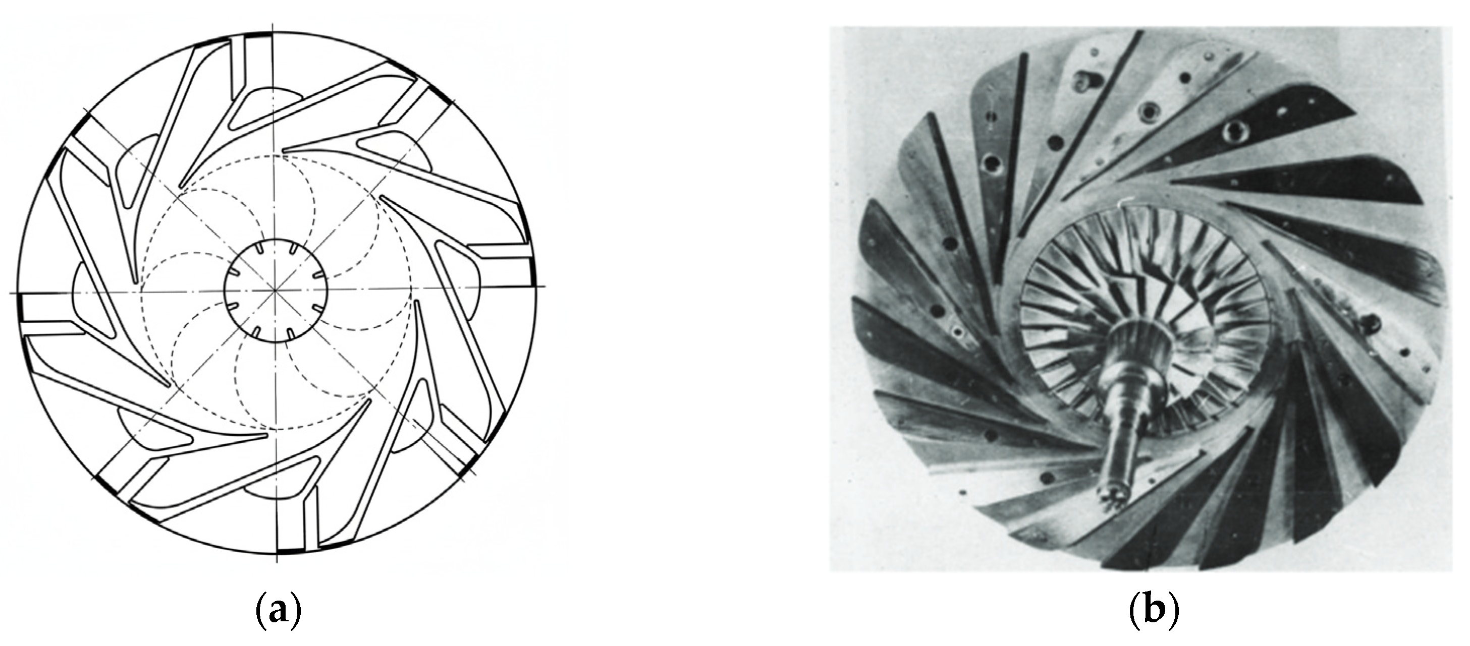
Pipe diffusers have become a promising design for enhancing efficiency and stability in high-pressure-ratio centrifugal compressors. They mitigate the effects of high inlet Mach number, handle distorted inlet flows, and enable cost-effective manufacturing. Pipe diffusers consist of multiple passages formed by drilling holes in an annular ring, creating vaneless, semi-vaneless, and pseudo-vaneless spaces upstream of the diffuser throat (Figure 8). The pseudo-vaneless space, characterized by ridges and a scalloped leading edge, generates pair vortices that influence flow mixing and boundary-layer behavior [70].
Extensive experimental and numerical studies have investigated the performance of pipe diffusers across various geometries and operating conditions. Pressure recovery has been evaluated through comparisons between predictions and experimental data, with the momentum integral method accurately predicting performance up to boundary-layer separation [73]. Beyond separation, pressure recovery effectiveness (η) is assumed constant (η_sep), which aligns with measured data within 3%, and additional tests support this assumption for conical diffusers with cone angles below 12° and subsonic inlet Mach numbers [74].
State-of-the-art CFD studies reveal that vortex pairs near the diffuser throat enhance mixing of high- and low-energy flows, thinning the boundary layer and reducing flow separation under adverse conditions, though they can also cause separation downstream by transporting low-momentum fluid to the pressure side [75]. Diffusers are crucial in fluid systems for reducing velocity and converting kinetic energy into pressure, improving efficiency and reducing losses. Optimizing diffuser geometry is complex due to the interplay of velocity, pressure, and turbulence, which traditional methods struggle to capture. Using CFD simulations with ANSYS Fluent 2024 R1 [76], investigated diffuser flow characteristics, showing how geometry affects velocity reduction, pressure distribution, and turbulence. The study highlights CFD’s effectiveness in predicting complex flow behavior and offers insights for improving diffuser design and efficiency.
Low-cost pipe diffusers with discrete drillings have also shown high efficiency in practice. In comparative studies against cambered-vane and flat-plate diffusers, a pipe diffuser achieved 81.8% efficiency at a 5.42 pressure ratio, exceeding benchmark designs by 6.8–8.8%. In follow-up tests, it reached 81.3% efficiency at a 6:1 pressure ratio, compared to 73% for the cambered-vane diffuser [77].
Performance evaluations under realistic operating conditions confirm that pipe diffusers can act as the controlling element for both choke and surge. Among different geometries, a 24-passage non-conical diffuser maintained performance nearly identical to a 32-passage conical baseline, while a 20-passage square-inlet diffuser exhibited higher losses, lower recovery, and greater throat blockage [78]. These results highlight the importance of favorable geometric features such as forward extensions (cutwaters) and curved throat walls for maintaining high performance.
Experimental investigations combining steady, unsteady, and laser-optical techniques have further elucidated the internal flow physics. Nominal-condition measurements consistently show flow separation on the pressure side in the first half of the diffuser, with minimal deceleration in the final 30% of the passage [79]. Parameter variations—including bleed flow, impeller tip clearance, and impeller–diffuser misalignment—reinforce this observation, motivating design proposals such as shortening the diffuser to mitigate separation.
Parametric CFD studies on highly loaded centrifugal compressors, including those originally equipped with wedge diffusers, show that pipe diffusers improve performance by producing a diffuse inlet flow pattern, reducing flow distortion, and limiting separation within discrete passages. These mechanisms collectively enhance stage efficiency and stability, confirming the pipe diffuser as an effective design choice for modern high-pressure-ratio compressors [80]. In a 100 kW micro gas turbine, CFD analysis of an optimized pipe diffuser demonstrated slightly lower efficiency (82.2%) than an airfoil diffuser (84.4%) at design flow but offered a more compact frontal area. The leading-edge geometry generated counter-rotating vortices, which improved flow in pseudo- and semi-vaneless spaces while inducing separation in the channel passages [75].
Building on these principles, Liu et al. [81] proposed a comprehensive methodology for fishtailed pipe diffusers. This approach defined throat and outlet areas using gas-dynamic functions, established the centerline through angle distributions, and specified cross-sectional profiles along the centerline. When applied this to NASA’s High-Efficiency Centrifugal Compressor (HECC), numerical analysis indicated that the fishtailed pipe diffuser improved total pressure ratio and isentropic efficiency across the operating range, achieving increases of 2.7% and 2.4 percentage points, respectively, at the design point [82]. These results demonstrated the effectiveness of structured design methodologies for pipe diffusers and highlighted the impact of geometry and leading-edge vortices on compressor performance and flow stability.
Bennett [83] conducted a comparative study of centrifugal compressor performance using pipe and wedge diffusers (Figure 9). The results indicate that the pipe diffuser performs better at high operating speeds (above 80% of design speed), as its leading edge promotes smoother flow diffusion and reduces the risk of separation. Conversely, at lower speeds near surge conditions, the wedge diffuser demonstrates superior performance. In these conditions, the pipe diffuser experiences higher friction losses and reduced pressure recovery, whereas the wedge diffuser maintains more stable flow and better efficiency. This comparison highlights the importance of selecting diffuser geometry based on the expected operating range and illustrates the trade-offs between high-speed efficiency and low-speed stability in centrifugal compressors.

2.2. Key Aerodynamic Principles

Centrifugal compressor diffusers play a critical role in converting the high-velocity flow exiting the impeller into static pressure, thereby improving stage efficiency. The primary aerodynamic function of a diffuser is flow deceleration, where the reduction in kinetic energy is converted into pressure recovery, often quantified through the pressure recovery coefficient (Cpr) or diffuser efficiency (η) [83,84]. The effectiveness of this conversion depends on the flow’s interaction with the diffuser walls, geometric design, and operating conditions.
Boundary-layer behavior is a key factor influencing diffuser performance. Growth of the boundary layer along the diffuser walls can lead to flow separation, which reduces pressure recovery and increases losses. Factors such as wall curvature, diffuser length, divergence angle, and inlet velocity profile critically affect the likelihood of separation [85]. Techniques such as the introduction of vanes, fillets, and pseudo-vaneless spaces can mitigate separation by guiding the flow and enhancing momentum transfer near the walls.
In complex diffuser geometries, such as pipe diffusers [86,87], pair vortices and secondary flows emerge due to flow interaction with structural features like scalloped leading edges. The interaction of vortical structures with the boundary layer is a critical factor in diffuser performance. Streamwise vortices, such as those generated by vortex generators, enhance mixing by promoting the exchange of high- and low-momentum fluid, thereby thinning the boundary layer and delaying separation near the diffuser throat [88]. However, these vortices can also transport low-momentum fluid toward regions of adverse pressure gradient, potentially leading to separation downstream. Therefore, understanding and controlling these vortical structures is essential to maximize both efficiency and flow stability in diffuser design [89].
The type of diffuser strongly influences flow guidance and overall performance. Vaned diffusers provide precise flow direction and high efficiency but often have a narrow operating range. Vaneless diffusers accommodate a wider flow range at the expense of peak efficiency [90,91]. Pipe diffusers, incorporating multiple passages and regions such as vaneless, semi-vaneless, and pseudo-vaneless spaces, exploit secondary flow patterns to balance efficiency and stability. Their unique design, including a scalloped leading edge, adapts to high Mach number incoming flows, reducing flow distortion and mitigating downstream separation. This makes them effective for high-pressure ratio centrifugal compressors [71,92].
Flow incidence at the diffuser inlet significantly impacts the performance and stability of centrifugal compressors. Misalignment or high incidence angles can lead to early flow separation, reducing pressure recovery and potentially causing surge. Conversely, proper alignment ensures uniform flow deceleration and stable operation. Predictive tools, such as the range-incidence correlation, are commonly used to estimate the operating envelope from choke to surge, aiding in the design of diffusers that balance efficiency and stability [93,94].
Key geometric design parameters—including inlet-to-impeller exit radius ratio, throat area, divergence angle [95,96], passage number [97,98], and cross-sectional shape [99]—significantly influence aerodynamic performance. These features affect vortex intensity, boundary-layer development, and overall flow stability, thereby determining both the maximum efficiency and operating range of the stage. Furthermore, diffuser design directly impacts compressor surge margin and stall behavior; configurations that reduce backflow and promote uniform exit flow enhance stage stability [100,101,102].
Overall, the aerodynamic principles governing compressor diffusers emphasize a careful balance between pressure recovery, efficiency, and operating range. The integration of design features such as vanes, fillets, pseudo-vaneless spaces, and optimized passage geometry allows modern diffusers—particularly pipe diffusers—to achieve high efficiency while maintaining robust flow stability under varying operating conditions [103]. A short summary of the diffuser types and their properties is presented in Table 2.

3. Design Methodologies

3.1. Empirical Correlations

In the dimensional analysis of radial compressor diffusers, the primary objective is to identify the key non-dimensional key parameters that govern diffuser performance. These dimensionless groups are crucial because they enable engineers to generalize design behavior and predict performance across varying sizes and operating conditions, ultimately facilitating scalable and efficient diffuser designs.
One of the most influential parameters is the diffuser area ratio (AR), which directly impacts pressure recovery. A higher AR (3) can enhance flow deceleration, which is desirable for pressure recovery, but it also increases the risk of flow separation. As such, it is a critical sizing parameter in both vaned and vaneless diffuser configurations.
A R = A e x i t A i n l e t
Another significant factor is the Mach number (Ma) (4), particularly at the impeller exit. Higher Mach numbers can increase the likelihood of shock formation and flow separation within the diffuser. While diffuser flows are generally subsonic, conditions near the impeller exit can become transonic in high-speed compressors. This parameter, which can be calculated with the local flow speed (V), the adiabatic exponent (γ), the specific gas constant (R) and static temperature (T), influences how much the flow can be decelerated without incurring performance losses.
M a = V γ R T
The Reynolds number (Re) (5) also plays a vital role, as it governs boundary layer characteristics, the transition to turbulence, and associated friction losses, taking into account the scale of the flow which is dictated by the local density of the fluid (ρ), flow speed (V), characteristic length (D) and dynamic viscosity (μ). In compact gas turbines, low Reynolds numbers can result in laminar or transitional boundary layers, which are more susceptible to separation, negatively impacting diffuser efficiency.
R e = ρ V D μ
Closely related to performance is the diffusion factor (DF) (6), which quantifies the extent of flow deceleration in the diffuser. When DF values exceed approximately 0.4–0.5, there is a high risk of flow separation in internal flows [104]. This parameter serves as a direct performance indicator, tightly linked to diffuser geometry and aerodynamic loss.
D F = 1 V e x i t V i n l e t
In vaned diffusers, blade solidity (σ) (7) becomes an important geometric factor. Higher solidity—achieved through narrower blade spacing (dictated by smaller distances between blades (s)) or longer blades (marked by higher chord (c) values)—generally improves pressure recovery by providing better guidance to the flow [105]. However, it also increases blockage and makes the diffuser more sensitive to incidence angle, presenting a trade-off between diffusion efficiency and operational flexibility.
σ = c s
The stage flow coefficient (Φ) (8) is another important dimensionless group, reflecting the ratio of flow capacity (determined by the mass flow rate (m) total density (ρ) at inlet) to the rotational speed (n), in revolutions per minute, and size of the system, described by the radius at the impeller discharge (r). This coefficient helps define operating conditions and is essential for matching the diffuser to the compressor system or stage.
Φ = m ˙ ρ π 2 r 3 n 30
Finally, the total pressure recovery coefficient (Cp) (9) is a direct measure of diffuser efficiency. It is influenced by all the aforementioned geometric and flow parameters, including Area ratio, Mach number, Reynolds number, and flow angles. As a primary optimization target in diffuser design, this coefficient not only evaluates performance but also informs optimal sizing and alignment with the compressor’s operating point. This coefficient is defined by the ratio of the pressure difference between the discharge and the inlet and the absolute difference between the total and static pressures at inlet.
C p = P e x i t P i n l e t P t , i n l e t P i n l e t
Together, these non-dimensional parameters provide a robust framework for analyzing, designing, and optimizing radial compressor diffusers across a range of operating conditions.
The Aspect Ratio (AS)—often defined as the blade height to chord ratio in vaned diffusers or height-to-width in vaneless designs—and the Area Ratio (AR)—the outlet-to-inlet area ratio (A2/A1) of the diffuser—are fundamental geometric parameters that critically shape centrifugal compressor performance. A high AS can enhance pressure recovery by facilitating a more gradual diffusion but also raises the risk of boundary layer separation and poses integration challenges in compact designs [106]. In contrast, a lower AS promotes flow stability and compactness, yet may compromise diffusion efficiency [107]. Similarly, a high AR supports greater pressure rise by enabling more substantial deceleration but can lead to instability, especially at elevated Mach numbers, while a low AR favors stability and compactness at the expense of pressure recovery. Striking an optimal combination of AR and AS requires balancing aerodynamic effectiveness with flow control demands and depends heavily on design constraints such as target pressure ratios, spatial limitations, inlet Mach number, and diffuser type (vaned vs. vaneless).
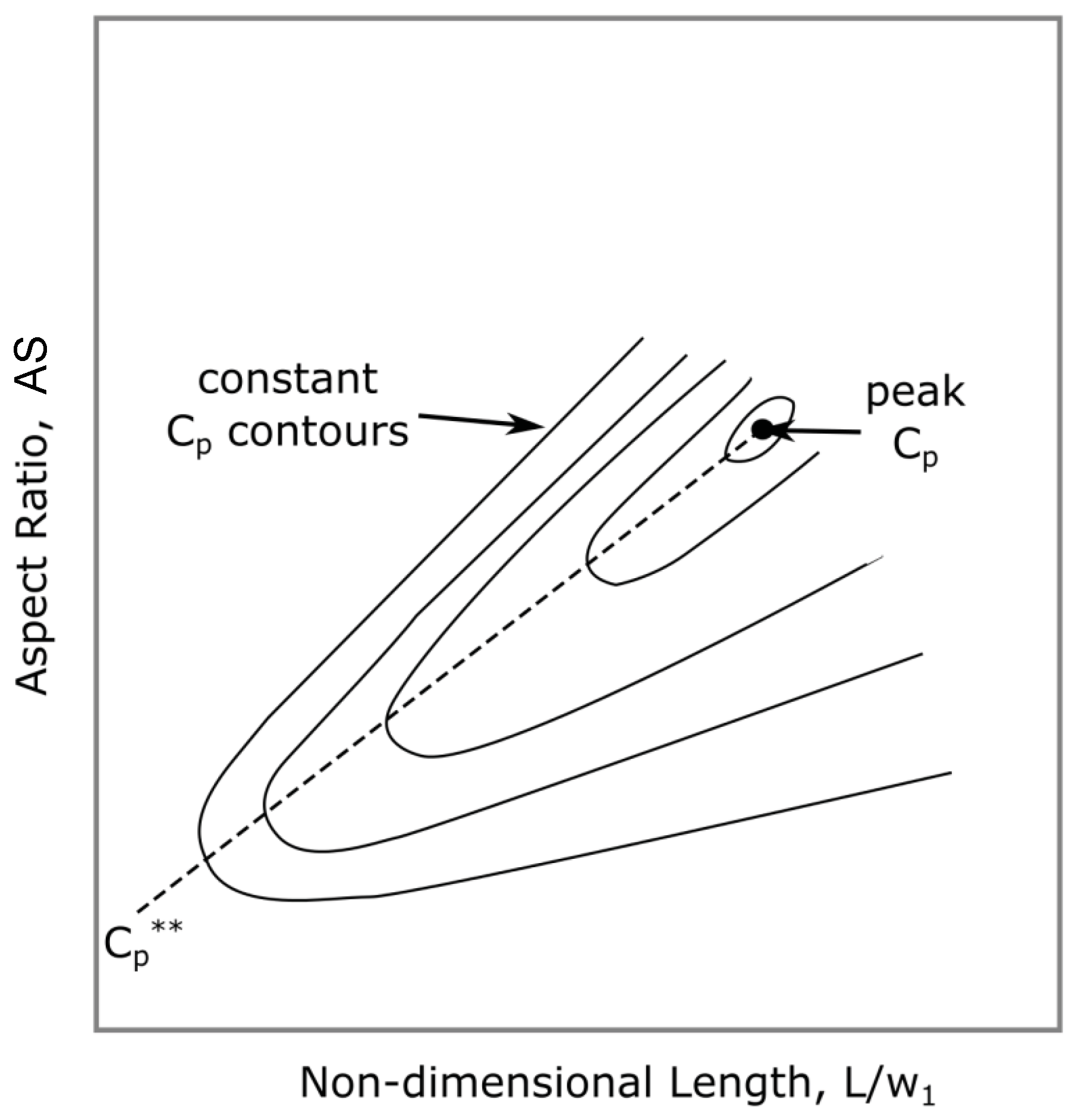
Diffuser effectiveness is typically evaluated using the pressure recovery coefficient, which measures actual pressure gain against the ideal isentropic value in one-dimensional flow. Another critical metric is the blockage factor at the diffuser throat—defined as the ratio of effective flow area (reduced by viscous boundary layers) to the geometric throat area. Elevated blockage can drive choking at lower than designed mass flow rates, degrading stage performance. Performance is commonly visualized through pressure recovery maps, which hold key throat parameters (such as blockage, Mach number, and width-to-height ratio) constant while plotting curves of maximum pressure recovery (Cp) against AR as the diffuser length (L/w1) varies [108].
ς = C p C p , i
B = 1 A e f f e c t i v e A g e o m e t r i c
Koch’s [109] pioneering work underscored the limitations of high AR blades, showing that reducing AR can improve surge margin. However, experimental findings also suggest that efficiency changes with AR can go either way depending on stage loading [110]. In transonic heavy-duty gas turbine compressors, optimization using Kriging and NSGA-II revealed that increasing solidity reduces losses from shock-wave–boundary-layer interaction, while lower AR reduces boundary-layer separation losses. This study achieved up to a 0.96% gain in isentropic efficiency and an 18.7% gain in stall margin. An optimal balance of spanwise solidity and AR—especially a solid tip-to-hub solidity ratio of at least 0.65—was crucial to radial load distribution and overall performance [111].
To et al. [112] investigate the optimal aspect ratio (AS) in compressor blades, emphasizing its role in aerodynamic performance, stability, and efficiency. A linear repeating stage method allows accurate flow decomposition even at very low ARs (down to 0.5), revealing that endwall losses are not directly inversely proportional to AS as traditionally assumed, but are better predicted by a new metric—“effective aspect ratio”—which depends on static pressure rise and geometry. At very low Aspect Ratios, interactions between endwall flows cause spanwise separation, impacting performance. A low-order model suggests that optimum AS is governed by blade thickness and endwall configuration (e.g., shroud vs. cantilever), rather than AS alone.
Table 3 summarizes the key geometric parameters and their aerodynamic effects in centrifugal compressor diffusers.
In turbomachinery design, specific speed (Ns) and specific diameter (Ds) are key dimensionless parameters used to characterize and scale compressor performance across different sizes and operating conditions. They provide a basis for selecting empirical correlations and loss models by relating geometric and operating variables.
Specific speed (Ns) (12) is a critical non-dimensional parameter in centrifugal compressor design, characterizing the relationship between rotational speed, flow rate, and pressure rise. It strongly influences diffuser selection and geometry: low specific speeds, typical for high-head, low-flow applications, favor vaned or channel diffusers that provide precise flow guidance, while high specific speeds, associated with high-flow, low-head compressors, are better suited to vaneless or low-solidity designs. It depends on the angular speed (N) in radians per second, volumetric flow rate (Q), on the gravitational acceleration (g) and on the total stage head (H).
N s = N Q g H t 3 / 4
Specific diameter (Ds) (13) relates impeller diameter to flow rate and head, guiding geometric scaling of the stage and diffusers.
D s = D H 1 / 4 Q 1 / 2

3.2. Analytical Models

Analytical modeling of diffusers provides a fundamental understanding of flow behavior and helps predict diffuser performance during the preliminary design stage. Several common analytical approaches are used to describe the fluid dynamics within compressor diffusers.
One-dimensional flow models simplify the flow to a single dimension, using basic conservation laws to estimate pressure recovery and velocity changes, typically assuming steady, incompressible or weakly compressible flow while neglecting complex 3D effects. This makes them ideal for early-stage sizing and performance assessment. Fast and resource-efficient, 1D calculations help guide key design choices such as compressor staging, boundary conditions, and variable guide vane operation. Over time, these methods have advanced through models like the Single-Zone approach, which assumes uniform flow, and the more detailed Two-Zone model by Japikse [118], which incorporates jet-wake structures within the impeller. Isentropic flow models represent an idealized diffuser operation where the flow process is reversible and adiabatic, implying no losses. These models use isentropic relations derived from thermodynamics to predict the maximum theoretical pressure recovery for a given velocity reduction. While providing an upper bound for performance, real diffusers always exhibit losses due to friction, turbulence, and flow separation. To account for these real-world losses, loss models incorporate empirical or semi-empirical coefficients representing pressure losses due to viscous effects and flow irregularities. These losses are often modeled as a fraction of the dynamic pressure and are critical for realistic performance predictions. The diffuser’s diffusion factor and pressure recovery coefficient are key parameters in these models, quantifying how effectively the diffuser converts velocity into pressure. Additionally, velocity triangle analysis is frequently employed to relate the velocity components at the diffuser inlet and outlet. By resolving the flow into axial and tangential components, this method aids in understanding how flow direction and magnitude change through the diffuser channels, thereby influencing pressure rise and flow stability.
A FORTRAN program was developed by Galvas [119] for predicting the off-design performance of centrifugal compressors with channel diffusers, requiring detailed geometric input for the impeller and diffuser. It estimated losses using analytical models and empirical correlations based on velocity diagrams and geometry, and calculated performance across a range of inlet velocities on a speed line. The output included efficiency losses, overall efficiency, and total pressure ratio between surge and choke. A validation case showed good correlation with limited experimental data from a commercial compressor. Aungier [120] introduced a comprehensive mean streamline performance prediction method based on total pressure losses for centrifugal stages, demonstrating good agreement with experimental data for turbocharger compressors with pressure ratios up to 3.5. Similarly, Oh et al. [121] have developed an enthalpy-based loss system which displays good results through compressor maps comparable to experimental data. While both single- and two-zone models approximate real flow behavior, higher accuracy can be achieved with 2D throughflow models, such as those proposed by Casey and Robinson [122], although these do not account for cross-flows normal to the analysis plane [123]. This is a limitation, as flow in centrifugal compressors has been shown to exhibit significant three-dimensional effects [124].
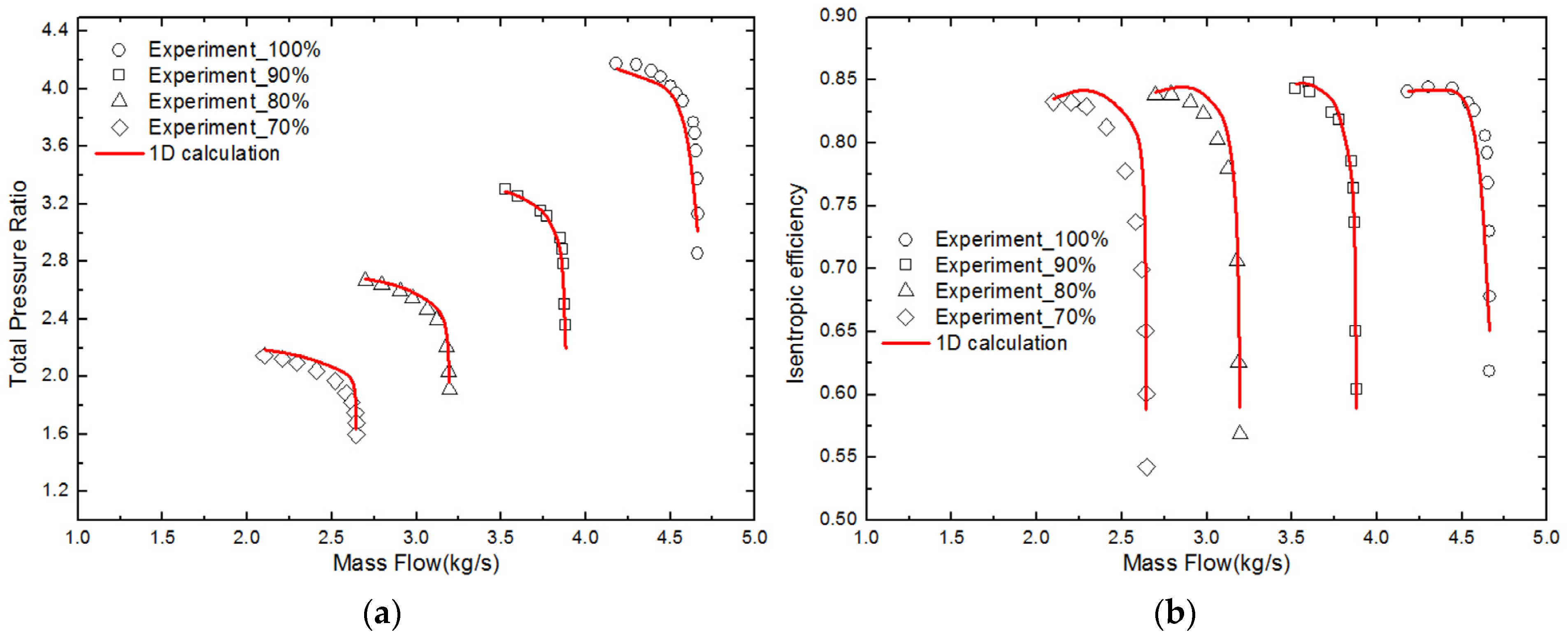
Li et al. [125] combined Aungier [126] loss model to calculate losses in the vaned diffuse with an optimization design completed using iSIGHT commercial software through an adaptive simulated annealing algorithm. They matched the optimization of the vaned diffuser with the radial compressor impeller based on the required throat area. Comparison with experimental data for the HPCC impeller showed good agreement at 100% rotational speed, but significant errors—over 20%—occurred at off-design conditions, especially at 60% speed. Comparisons between the 1D calculation results and experimental data for the HPCC impeller with a vaned diffuser were presented in Figure 10.
Another method for evaluating the matching between the impeller and vaned diffuser was proposed by Caser [127]. Experimental results from high-pressure turbocharger stages with varying diffuser throat areas and impeller types show that performance changes with speed and geometry can be explained using this parameter. According to this approach, if both the impeller and the vaned diffuser choke simultaneously, the theoretical ratio of the impeller outlet area to the diffuser throat area is:
A d * A i * = 1 + k 1 2 D 1 D 2 2 M u 2 2 k + 1 2 k 1 1 + k 1 λ M u 2 2 n + 1 2 n 1
A widely used approach for centrifugal compressors stages (including impeller, vaneless and vaned diffuser and volute), developed by Aungier in the 1990s, has been applied to various test cases, showing good agreement with experimental data across a broad operating range. However, near choke and stall conditions, deviations occur. To improve accuracy, standard empirical loss models—such as those for choking, incidence, and shock losses—Klausner et al. [128] replaced them with more physically based models, some of them focusing on incidence loss, boundary layer blockage and chock mass flow. The revised method was revalidated against existing data and showed improved performance predictions, particularly outside the original model’s range. Remaining limitations included overestimation of vaneless diffuser losses at low mass flow and uncertainty in choke limit prediction.
Hong et al. [129] developed an optimization approach for centrifugal compressors using a one-dimensional impeller–diffuser throat area model. Key findings include that increasing the diffuser throat area raises choking mass flow at low and medium speeds but has minimal effect at high speeds. Choking tends to occur in the diffuser at lower speeds and at the impeller inlet at higher speeds. Based on 1D analysis, the vaned diffuser was optimized, leading to a ~2% increase in stage efficiency and improved performance across all speed lines. The 1D model effectively predicts matching throat areas where both impeller and diffuser choke simultaneously, enabling better stage matching and broader operating range. In the same time Yang et al. [130] proposes an improved one-dimensional (1D) meanline prediction method for centrifugal compressors with splitter blades, addressing the limitations of existing simplified models. Key developments included: (1) the introduction of a general meridional channel to reduce geometric input requirements and define splitter blade leading edge positions; (2) a stepwise calculation method that treated blade sections with different splitter rows as separate sub-impellers, enhancing prediction accuracy; (3) optimization of loss model coefficients using a multi-objective genetic algorithm (NSGA-II), which resulted in improved performance prediction across various impeller types; and (4) plans for further validation with additional impeller configurations to enhance the generality of the model.
Accurate prediction and control of these losses are essential for diffuser design and performance optimization, especially when aiming to balance pressure recovery, efficiency, and stability across the full compressor operating range. Losses in the vaneless diffuser arise primarily due to wall friction and the influence of the absolute flow angle. These losses are typically evaluated using the correlation proposed by Stanitz [131]:
Δ h v l d = C p T 02 p 3 p 03 γ 1 / γ p 3 p 02 γ 1 / γ
For the losses in the vaned diffuser, Aungier [20] presents a method of efficiency estimation based on total pressure loss coefficients. The total pressure at the vaned diffuser discharge is calculated by:
p 04 = p 03 p 03 p 3 i ω i
in which ωi is a total pressure loss coefficient. Aungier categorized them into the following types:
  • Incidence losses—caused by the mismatch between the incoming flow angle and the vane inlet angle, which can be expressed using the flow velocity at the entrance of the diffuser (C3) and the optimum (or minimum-loss) speed defined by:
    C 3 * = C m 3 s i n β 3 s i n α t h
    in which Cm3 is the meridional velocity at the diffuser inlet, αth is the flow angle at the diffuser throat, approximated by arcsin(Ath/A3), and β3 is the blade metal angle at the diffuser inlet. The loss coefficient is given by:
    ω ¯ i = 0.8 C 3 C 3 * C 3 2
  • Skin friction losses—resulting from boundary layer development along the vane surfaces and endwalls.
    ω ¯ S F = 4 c f C ¯ C 3 2 L B d H 2 δ d H 0.25
    in which cf is the friction coefficient, LB is the diffuser blade mean camberline length, dH is the mean value of the throat and the tip hydraulic diameters, C ¯ is the root mean square of the inlet and discharge diffuser absolute velocities, δ is the boundary layer thickness at mid-passage.
  • Choking Loss—occurs when the diffuser reaches its flow capacity, limiting mass flow and increasing losses near the choke limit. To determine this pressure loss coefficient, Aungier introduces a parameter X, defined by:
X = 11 10 C r A t h A c r
In which Cr is the contraction ratio of the diffuser, Ath is the throat area of the diffuser and Acr is the critical area of the flow at the diffuser inlet. The loss is calculated by:
ω ¯ c h = 0 , X 0 0.5 0.05 X + X 7
  • Wake Mixing Loss—caused by mixing of high- and low-momentum fluid in the wake regions behind the vanes, leading to additional entropy generation.
    ω ¯ m i x = C m , w a k e C m , m i x C 3 2
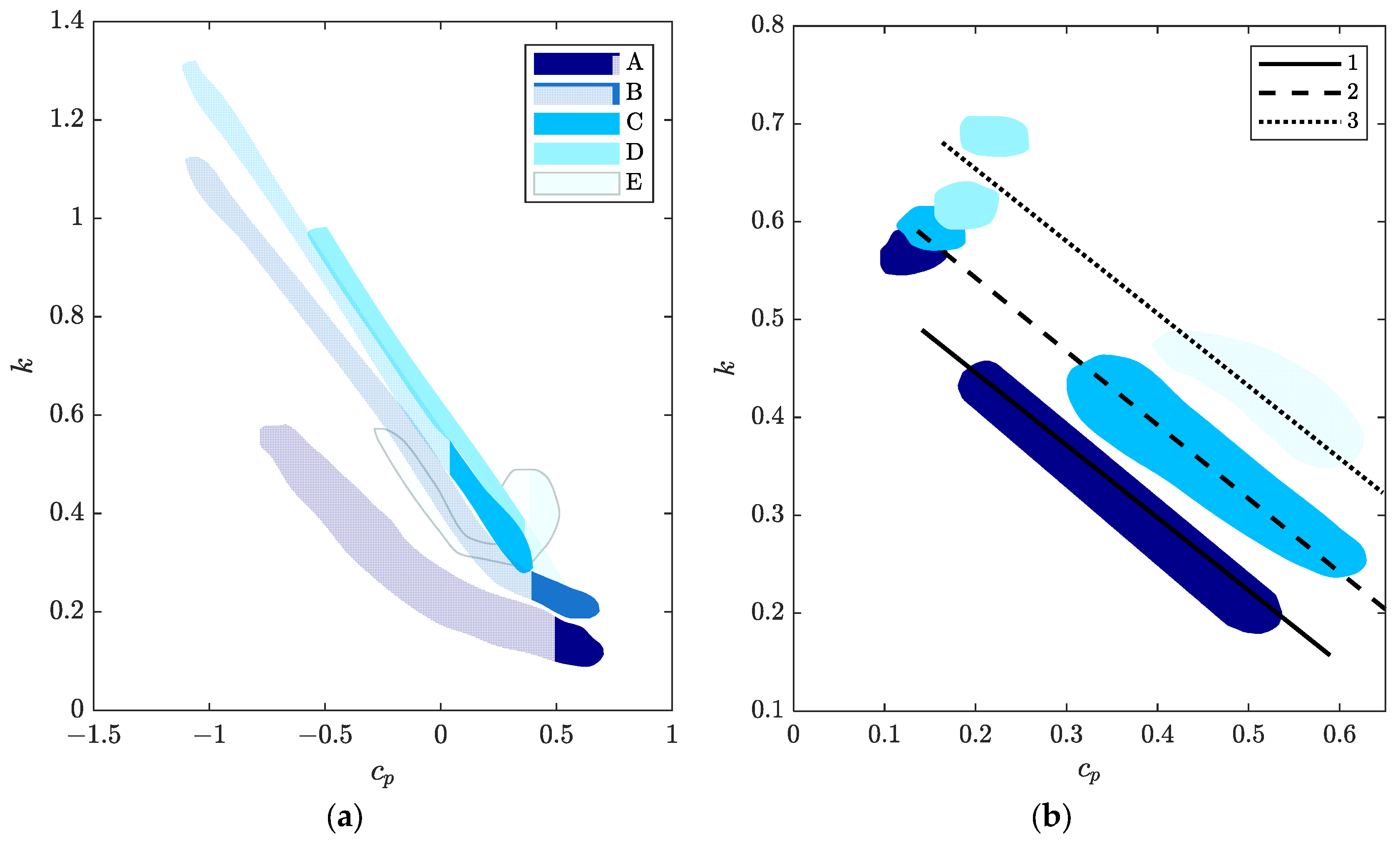
Figure 11 illustrates the off-design performance of the entire cascade, represented by two key parameters: the pressure coefficient (Cp) and the kinetic energy loss coefficient (k). To further validate the loss-map methodology, Figure 11b presents an additional example in which the combined performance of the vaneless diffuser, return bend, and return channel is evaluated. In this case, the overall system is characterized by a single set of Cp and k values, providing an integrated view of losses across the entire flow path.
While analytical models provide valuable insight into the fundamental behavior of compressor diffusers, they come with inherent limitations due to the simplifying assumptions involved. One of the primary challenges is the inability of basic analytical models to fully capture complex three-dimensional flow phenomena such as flow separation, secondary flows, turbulence, and unsteady effects that are common in real diffuser operations.
Most analytical approaches assume steady, uniform flow and neglect variations in velocity and pressure across the diffuser cross-section. This simplification often leads to discrepancies when compared with experimental data or high-fidelity computational fluid dynamics (CFD) simulations, especially under off-design conditions where flow separation and recirculation zones can significantly reduce diffuser efficiency.
Additionally, the empirical loss coefficients used to represent viscous and turbulence-induced losses are often derived from limited experimental datasets and may not be universally applicable across different diffuser geometries or operating regimes. These coefficients typically need calibration or adjustment for each specific design, limiting the predictive capability of purely analytical models.
To overcome these limitations, analytical models are frequently extended or complemented by semi-empirical correlations and numerical methods. For example, incorporating boundary layer growth models and separation criteria can improve predictions of diffuser performance at higher diffuser angles or flow Reynolds numbers. Moreover, coupling analytical models with CFD results or experimental data allows designers to refine loss coefficients and validate assumptions, leading to more accurate performance assessments.
Recent advances also explore hybrid modeling approaches where simplified analytical models serve as the backbone, enhanced by data-driven techniques such as machine learning or reduced-order modeling. These extensions aim to balance computational efficiency with improved accuracy, facilitating faster and more reliable diffuser design iterations. Despite their limitations, analytical models remain an indispensable tool in compressor diffuser analysis, providing quick estimates, guiding design decisions, and serving as a foundation for more advanced modeling techniques.

3.3. Integration of 1D and CFD Methods in Diffuser Design
The aerodynamic design of centrifugal compressors increasingly relies on the integration of one-dimensional (1D) modeling and Computational Fluid Dynamics (CFD) to balance speed, flexibility, and physical accuracy. While 1D methods are fast and computationally efficient, they simplify the flow physics and often rely on empirical correlations. CFD, on the other hand, captures detailed, three-dimensional, viscous flow structures that are essential for understanding complex phenomena—especially under off-design conditions.
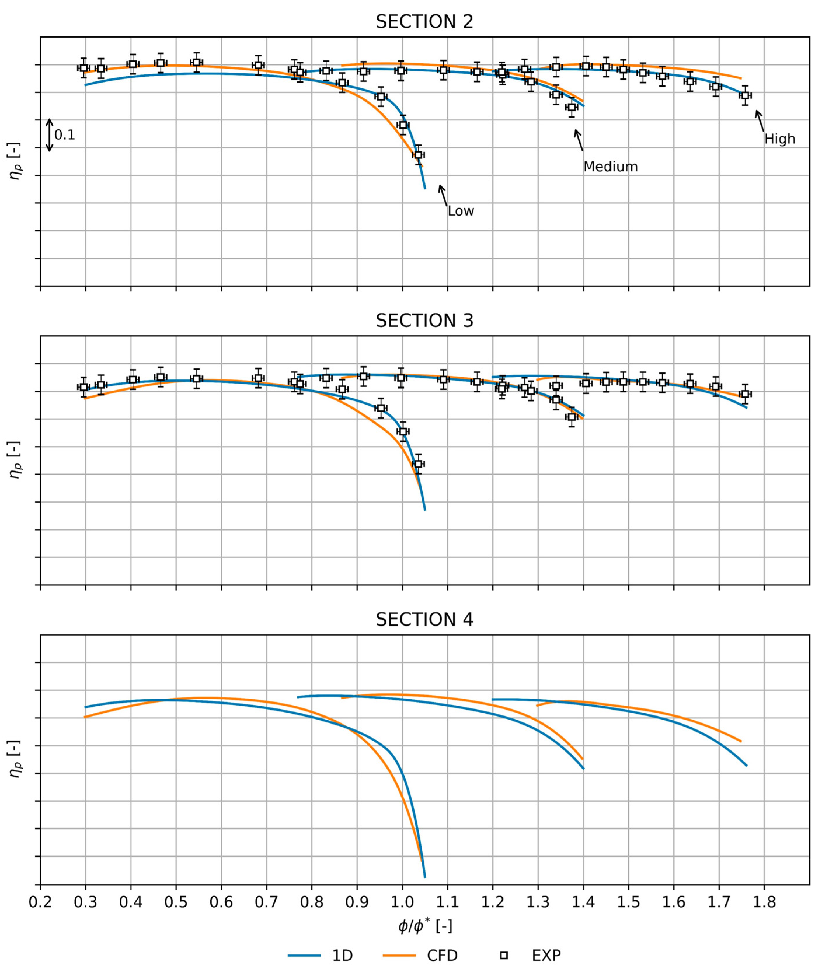
Recent studies have demonstrated that 1D modeling can be significantly enhanced by coupling it with optimization techniques, such as genetic algorithms and multi-objective comparisons, to calibrate empirical coefficients (e.g., for deviation angle, work input, and efficiency). For example, Khoshkalam et al. [133] evaluated a centrifugal compressor’s performance through both 1D mean-line and 3D RANS simulations, validated by experimental data. A 1D model, developed using key loss mechanisms, analyzed how impeller and diffuser geometries affect pressure ratio, surge margin, choke, and operating range. Key findings indicate that increasing impeller blade height and diffuser outlet diameter improves pressure ratio and operating range but affects surge margin and choke differently; variations in impeller inlet diameter and blade angles also significantly influence performance metrics. Loss analysis identified skin friction, diffusion, blade loading, and recirculation as dominant factors impacting compressor efficiency, while clearance, disk friction, incidence, and mixing losses were less significant. To support the evolving needs of centrifugal compressor design amid the energy transition, Bicchi [134] introduced a rapid and flexible methodology that combines a 1D single-zone model with artificial neural networks (ANNs). This approach significantly reduces design time—from about a month to under a week—while maintaining prediction errors below 1%, making it highly effective for early-stage aerodynamic development despite relying on simplified 1D assumptions. Validation results, shown in Figure 12, demonstrate strong agreement between the 1D model, CFD simulations, and experimental data, particularly at the diffuser outlet. The largest deviations, 4.98% at Section 2 and 3.55% at Section 4, remain within acceptable limits, reflecting the trade-offs of applying simplified models to complex 3D flow environments. Experiments on a turbocharger compressor further indicate that diffuser length-to-width ratios beyond 3.7 yield no performance improvement. Moreover, a short channel paired with a downstream vaneless diffuser matched the pressure recovery of an equivalent-diameter longer channel diffuser [113].
Diffuser geometry is a key determinant of passage performance.
Figure 13 presents an example of a pressure recovery map illustrating diffuser performance under fixed throat conditions, where parameters such as blockage, Mach number, and the width-to-height ratio at the throat are held constant. Building on this, Japikse [118] introduces a series of correlations that link key geometric and performance variables—including aspect ratio, pressure recovery coefficient (Figure 14), diffuser blockage, and length-to-width ratio (L/W)—to overall diffuser effectiveness, with particular focus on the optimal L/W configuration (Figure 15).
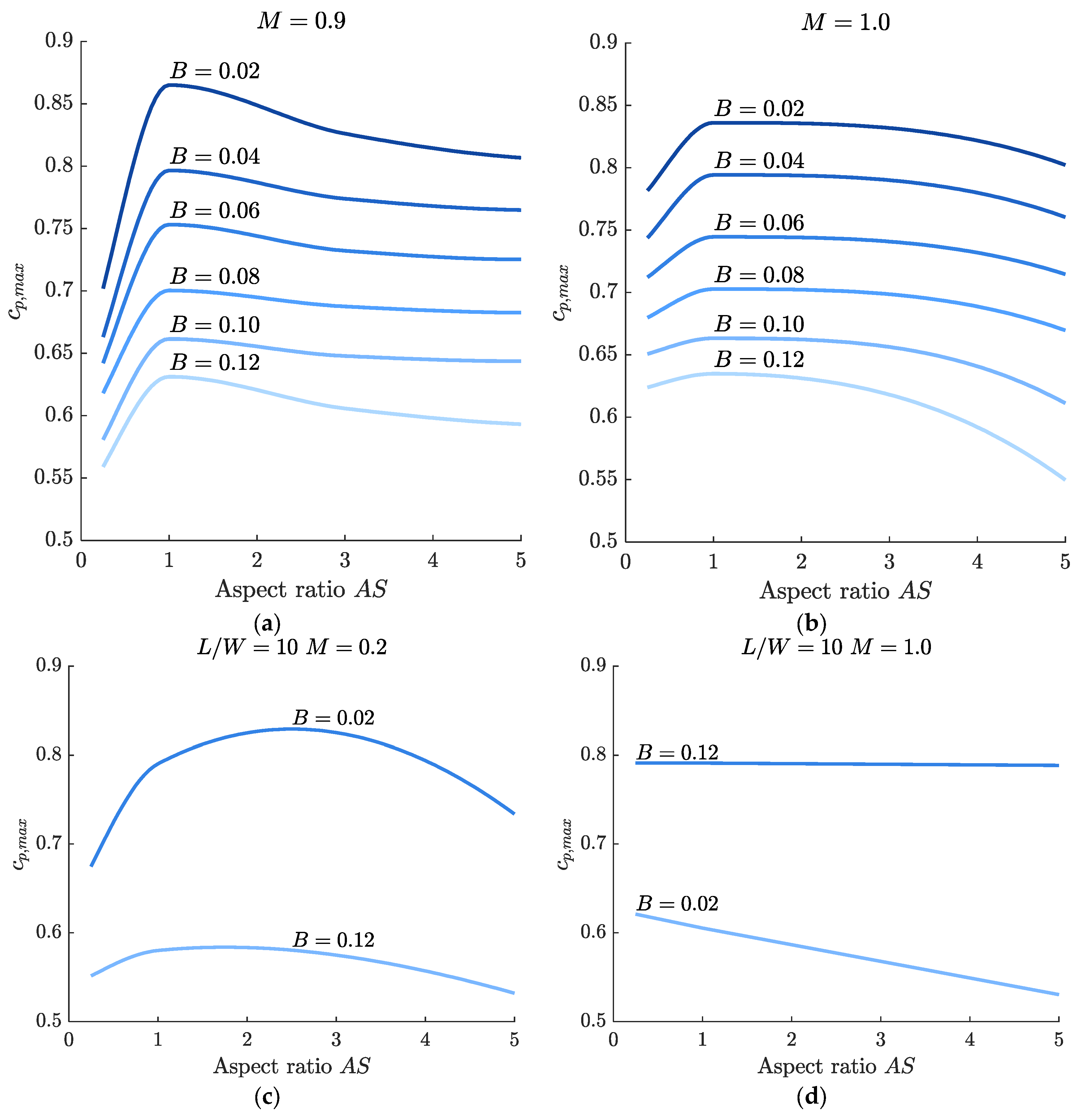
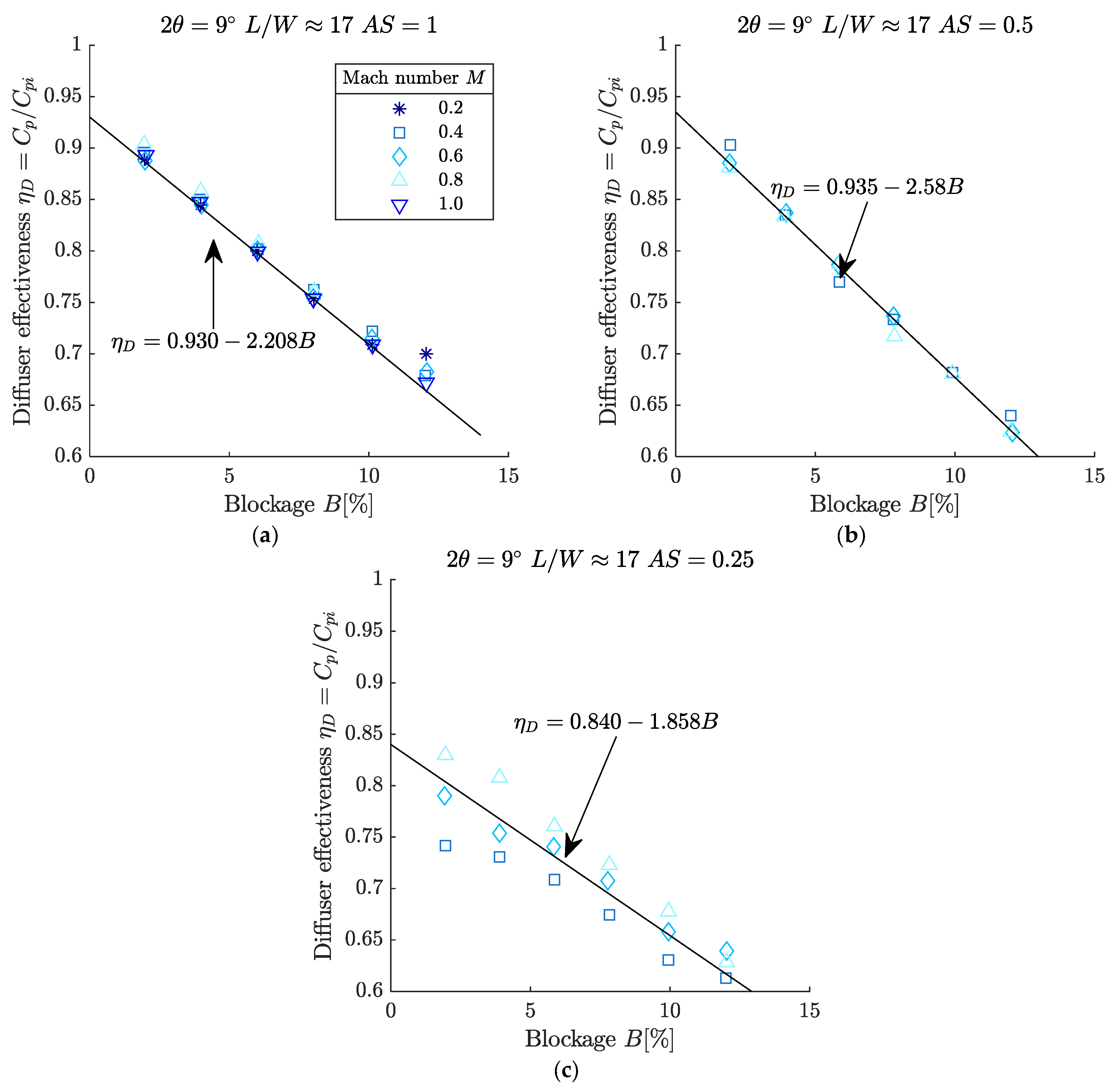
Figure 14 compiles a database of experimental results originally gathered by Runstadler and Dolan [135], highlighting both optimum diffusers (L/W ≈ 17, Figure 14a,b) and shorter, sub-optimal configurations (L/W = 10, Figure 14c,d). For diffusers operating at or near the optimum length, the choice of aspect ratio—either greater or less than unity—is primarily influenced by the expected level of inlet aerodynamic blockage. However, in real-world centrifugal compressor applications, achieving an aspect ratio of exactly one is often impractical due to packaging and integration constraints.
Figure 13. Example of a typical pressure recovery map for a subsonic 2D diffuser [136].
Machines 13 00990 g013
When the diffuser length falls below the optimum, the strong sensitivity to aspect ratio seen in the longer configurations diminishes considerably. Furthermore, at higher Mach numbers, low aspect ratio designs incur little to no performance penalty, making them more viable for high-speed flows. Additional variables—including inlet distortion, Reynolds number, and the intensity of inlet vorticity or turbulence—also play a significant role in shaping diffuser performance.
Figure 15 presents preliminary correlations relating diffuser performance to blockage (Figure 15a) and aspect ratio (Figure 15b), providing a useful tool for systematic design trade-offs. These correlations offer a practical foundation for estimating performance trends, identifying potential efficiency losses, and guiding early decisions on diffuser geometry and sizing. While preliminary in nature, such correlations should be validated against detailed diffuser maps tailored to the specific conditions of the target application.
Overall, these relationships serve as a valuable reference point in the early stages of rectangular-section diffuser design. They allow designers to make informed choices, anticipate performance trends, and optimize geometry before investing in detailed aerodynamic analyses or physical testing.
Figure 14. Peak pressure recovery versus aspect ratio: (a) optimum length diffusers (L/W ≈ 17) M = 0.9; (b) optimum length diffusers (L/W ≈ 17) M = 1; (c) shorter than optimum diffusers (L/W = 10) M = 0.2; (d) shorter than optimum diffusers (L/W = 10) M = 1.0 (redrawn based on Japikse [118]).
Machines 13 00990 g014
Figure 15. Channel diffuser effectiveness at optimum L/W: (a) AS = 1.0, 2θ = 9°; (b) AS = 0.25, 2θ = 9°; (c) AS = 5.0, 2θ = 9° (redrawn based on Japikse [118]).
Machines 13 00990 g015
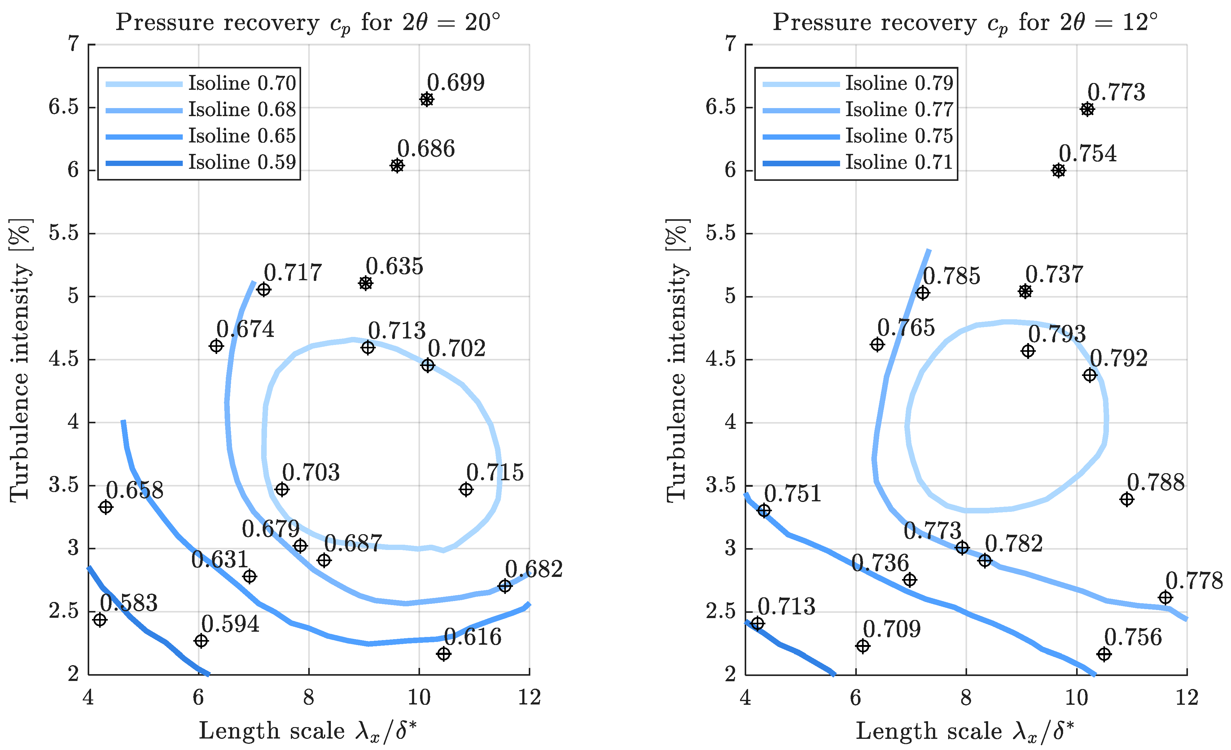
Passage diffuser performance is influenced by inlet conditions such as Mach number, Reynolds number, and turbulence characteristics. While Mach and Reynolds number effects are generally minimal—except in cases involving strong shocks or very low aspect ratios—turbulence intensity and structure have a significant impact. Figure 16 shows the pressure recovery performance for two diffusers with expansion angles of = 12° and 20°. The efficiency of both diffusers is significantly influenced by variations in turbulence intensity and the turbulence integral length scale. Optimal performance is observed when the turbulence intensity ranges between 4 and 8%, and the integral length scale is approximately eight times the inlet boundary layer displacement thickness [120]. Experimental results further validate these findings, showing an increase in static pressure recovery of 11.3% for the 12° diffuser and 23.9% for the 20° diffuser under these flow conditions. This enhancement is primarily due to large-scale turbulent eddies penetrating the boundary layer and transferring energy to near-wall regions, which reduces flow distortion and delays separation—particularly when the eddy axes are aligned with the diffuser walls [137].
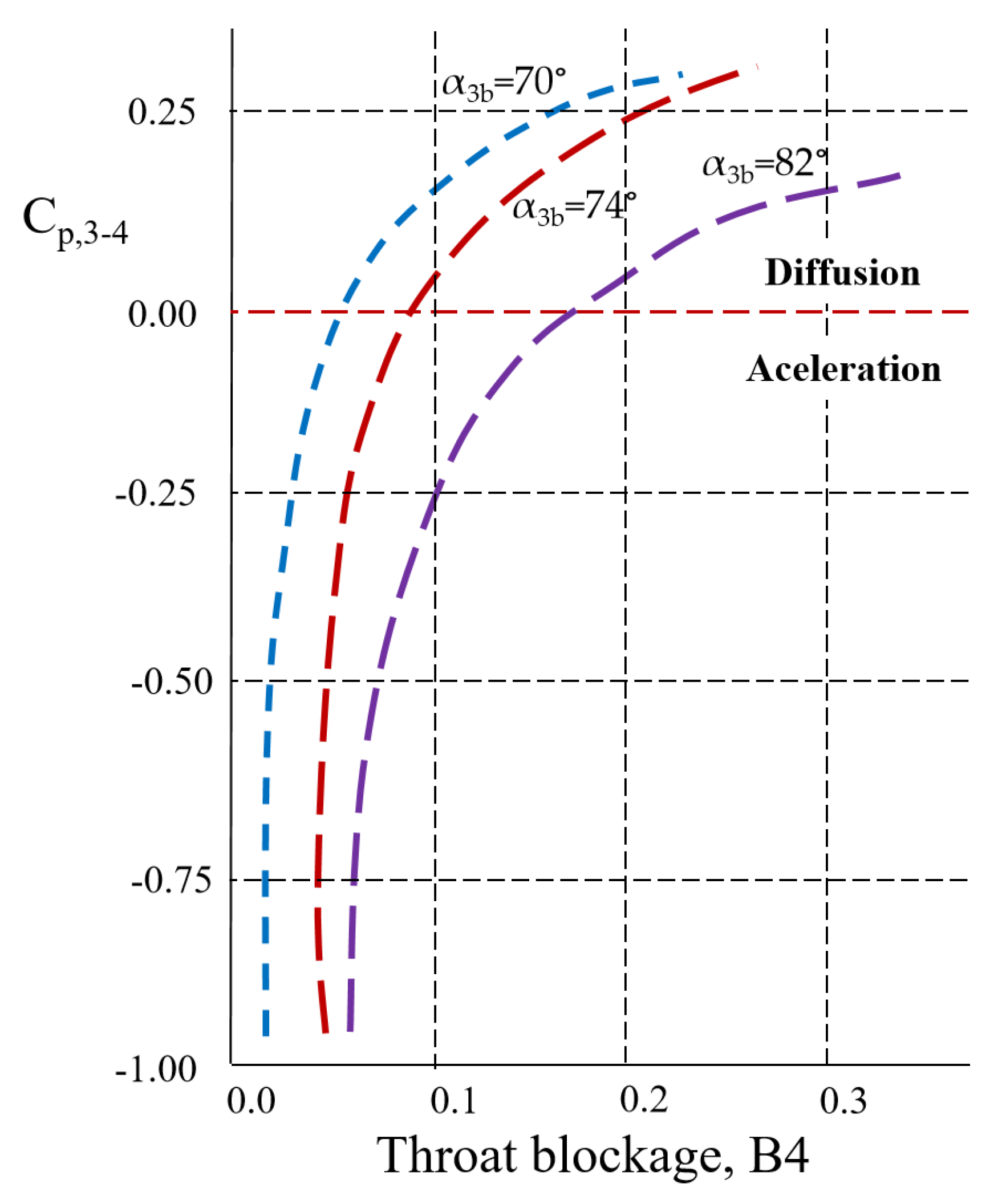
The region between the impeller tip and diffuser throat plays a crucial role in centrifugal compressor performance. High-velocity tip flows interact with the stationary diffuser, creating shear layers and potential flow separation, while tip leakage vortices can mix with the main flow, increasing losses and reducing efficiency. The flow must adjust from the impeller exit to the diffuser geometry, generating secondary flows and uneven pressure distributions, which are particularly sensitive to off-design conditions and can affect overall energy transfer. Figure 17 presents the overall pressure recovery of a typical channel diffuser plotted against the throat blockage. Correlations of this type, however, fail to capture important factors such as the optimum vane inlet radius (R3 = r3/r2), changes in diffuser passage width, and the influence of diffuser vane setting angles (diffuser throat—station 4, diffuser inlet radius—station 3).
Table 4 summarizes numerical studies from the last decade focusing on diffuser optimization. Collectively, these investigations highlight how the integration of 1D modeling, CFD, experimental validation, and geometric optimization strategies can guide the design of efficient, reliable centrifugal compressor diffusers under both design and off-design operating conditions.

4. Trade-Offs in Design

4.1. Design Constraints

Centrifugal compressors are typically optimized for peak efficiency and stability at their design point, where operating parameters such as mass flow, rotational speed, and pressure ratio meet target specifications. However, in real applications, compressors often operate under a broad spectrum of off-design conditions including partial loads, reduced speeds, and varying inlet conditions. Designing compressors to perform reliably across this range imposes several critical constraints:
  • Stability Margin: Off-design operation increases the risk of flow instabilities such as rotating stall, surge and choke, which cause pressure fluctuations, loss of performance, and potential mechanical damage [147]. Ensuring sufficient surge margin across the entire operating envelope constrains diffuser geometry, blade angles, and the use of variable inlet guide vanes (VIGVs) or bleed systems to control flow and delay stall onset [148,149]. Such a safety margin, also called a safety flow range, which assures the operation of compressor stages within the surge and choke limits, is presented in [150].
  • Efficiency Drop: Aerodynamic losses tend to increase under off-design conditions due to flow separation, increased secondary flows, and tip leakage effects. Compressor geometry must therefore balance aerodynamic efficiency at the design point with acceptable performance degradation at off-design conditions [151,152,153].
  • Flow Range and Flexibility: A wide stable operating range requires designs that accommodate variable mass flow rates without excessive distortion or separation. Variable geometry features such as VIGVs, vaned diffusers, or active flow control devices are commonly employed to enhance flexibility and control flow behavior [99].
  • Mechanical and Thermal Constraints: Off-design flow conditions can generate uneven aerodynamic loading and thermal stresses, which may impact blade life and structural integrity. The compressor design must address these mechanical limits through robust materials and structural optimization [154].
  • Control System Integration: The compressor must be compatible with control strategies such as surge control systems, bleed valves, and variable geometry actuators to maintain stable and efficient operation throughout the off-design range [155].
Meeting these constraints requires a multidisciplinary design approach combining aerodynamic modeling (1D and CFD), structural analysis, and control system design to ensure performance, durability, and operability across all expected conditions.
Centrifugal compressors are widely used in various industrial sectors such as aerospace propulsion, power generation, and automotive turbocharging due to their compact size and high efficiency near design conditions. However, their operational stability and efficiency often suffer under off-design conditions—such as reduced rotational speeds or partial loads—because of complex internal flow dynamics, particularly involving strong interactions between the impeller and diffuser stages. These off-design conditions frequently give rise to flow instabilities, including rotating stall and surge, which constrain the compressor’s stable operating range and reduce overall performance. The diffuser, situated downstream of the impeller, significantly affects flow behavior and pressure recovery. Various diffuser designs—vaneless, vaned, or twisted vaned—exhibit different stall characteristics and flow patterns, especially under off-design conditions. Understanding the complex interactions between the impeller and diffuser is critical for improving compressor stability and expanding operating range [156].
In turbocharger compressors, bleed air near the impeller exit, used for sealing and thrust balance, can reduce the stable operating range by up to 50%. Bleed modifies flow dynamics by reducing endwall blockage and destabilizing the vaned diffuser, resulting in rotating stall waves. Control strategies targeting endwall blockage have shown promising results in recovering 75% of the lost surge margin and improving compressor efficiency by one point [157].
Stable compressor operation is limited by rotating stall or surge, often preceded by two stall precursors: long-wavelength modal waves and short-wavelength “spike” inception [158]. While spike stall in axial compressors is linked to blade-tip leakage flow [159], its occurrence in centrifugal compressors with shrouded vaned diffusers—where leakage is absent—points to a different cause. Using unsteady 3D RANS simulations and experiments, the study shows that spike inception arises from flow separation near the vane leading edge, reversed radial flow carrying vorticity back into the vaneless space, and recirculation of low-pressure fluid increasing diffuser inlet blockage. Unlike axial compressors, here high swirl and uneven flow at the impeller exit replace leakage as the driver of endwall flow and stall onset [160]. Numerical analyses of stall and surge in centrifugal compressors with vaneless versus vaned diffusers reveal distinct pressure fluctuation patterns and backflow structures near surge. Vaneless diffusers tend to develop uniform stall effects across passages, whereas vaned diffusers experience more localized and variable stall impacts [161]. Experimental and CFD investigations show that diffuser stall originates from rotating vortices near the shroud, triggered by positive incidence angles at vane leading edges. These stall cells migrate from shroud to hub and into impeller passages as flow decreases, leading to stage stall and significant pressure fluctuations [162].
Numerical simulations of a centrifugal compressor with a wide vaneless diffuser reveal that rotating stall forms due to core flow instabilities. Initially, reflow develops at the hub side and moves toward the diffuser inlet; as the flow decreases, it shifts towards the shroud and eventually appears at both the hub inlet and the shroud outlet. This asymmetrical reflow causes radial core flow distortion, triggering stall, which is indicated by a sudden drop in static pressure head. Rotating stall occurs only when reflow develops at the diffuser outlet, with fluid mass flow rates growing and rotating opposite to the impeller at roughly 40% of its speed, forming a stable, self-sustaining stall pattern [163].
Stall behavior varies depending on the width of the vaneless diffusers: narrow ones stall due to boundary layer instability, wide ones from core flow instability. Moreover, diffuser length affects stall speed—long diffusers stall slowly, short ones quickly. Rotating stall causes flow separation, pressure fluctuations, and efficiency loss. Two main mechanisms that accompany rotating stall are reflow from the diffuser outlet at high flow and local separation near hub and shroud at low flow [164].
Diffuser stall in a centrifugal compressor with a vaneless diffuser occurs as a rotating stall cell at 25–30% of impeller speed, forming opposite the cutoff and strengthening near it. CFD simulations revealed the existence of a low-velocity region caused by the boundary layer separation interacting with the impeller discharge vortex, leading to flow blockage that expands with positive flow angles. The stall cell dissipates after passing the cutoff as mass flow recovers, confirming that diffuser stall is driven by flow separation and vortex interactions [165].
Stall behavior in a centrifugal compressor with a volute and vaneless diffuser occurs in two stages:
  • Stall I, at flow rates around 0.225–0.26 kg/s, involves localized impeller inlet spillage due to tip leakage vortex, causing minor flow fluctuations and reduced blade loading.
  • Stall II, at flow rates below 0.225 kg/s, develops as a full annulus stall with strong mass flow oscillations, sharp drops in pressure ratio and efficiency, and intense reverse flow. This escalates vortex strength and blade loading loss, impacting the diffuser. The volute promotes the transition from localized stall I to widespread stall II, which severely disrupts compressor performance [166].
Tandem impellers have been numerically proven to enhance efficiency and extend operating range at low speeds by suppressing low-momentum fluid movement, though benefits diminish at higher speeds due to increased flow losses [167]. This study computationally evaluates a high-pressure ratio supersonic mixed-flow compressor stage for small jet engines using an in-house mean-line 1D code. A RANS-based CFD model, validated against NASA Rotor 37 and RWTH Aachen data, captures 3D, viscous and shock effects. While the mean-line method predicted a pressure ratio of 6.0 at 75.5% efficiency for 3.5 kg/s, CFD results showed a slightly lower pressure ratio of 5.83 with 77% efficiency at 3.03 kg/s. Increasing rotational speed by 3.5% raised the pressure ratio to 6.12 at 75.5% efficiency. The study demonstrates that CFD improves design accuracy and identifies key areas for performance optimization [168].
Studies comparing compressors with narrow and wide operating ranges highlight the importance of tip leakage vortex breakdown in stabilizing flow at low rates, enabling wider operating ranges in turbocharger compressors [169]. Tip clearance and diffuser geometry strongly influence reversed flow and mixing losses. Larger tip clearances increase reversed flow and entropy generation, especially in unpinched diffusers, while pinched diffusers mitigate these effects, improving overall efficiency [170].
Overall, advancing the understanding of stall dynamics and flow interactions in centrifugal compressors through combined experimental and numerical approaches is vital for developing more stable, efficient, and reliable turbomachinery systems.

4.2. Performance Trade-Offs

The performance and stability of centrifugal compressors under off-design conditions are strongly influenced by diffuser behavior. One of the primary goals in diffuser design is to maximize pressure recovery by decelerating the flow. However, aggressive deceleration can thicken the boundary layer, leading to flow separation, pressure loss, and increased instability. CFD analyses show that designers must carefully limit the diffusion rate—through the area expansion ratio and diffuser angle—to avoid these issues. Typical guidelines suggest that wall angles exceeding approximately 7–10° [20] often result in separation unless additional mitigation strategies are employed.
Diffuser length is another key factor affecting off-design performance. Longer diffusers enable more gradual flow deceleration, reducing the risk of separation and improving efficiency. Conversely, longer diffusers increase weight, cost, and size, which can be prohibitive for aerospace or automotive applications. Shorter diffusers, while more compact, are exposed to stronger adverse pressure gradients that can compromise both efficiency and stability. CFD studies help quantify these trade-offs, allowing designers to balance compactness with flow reliability.
The choice between vaneless and vaned diffusers also significantly affects off-design flow behavior. Vaneless diffusers are simpler and more tolerant to swirl and non-uniform inlet conditions but typically achieve lower pressure recovery. Vaned diffusers, in contrast, provide better guidance of the flow and higher efficiency at the design point, yet they are more sensitive to separation and have a narrower operating range. CFD simulations demonstrate that vaned designs offer high performance under ideal conditions but require careful consideration when operating across a broad range of flows, whereas vaneless diffusers maintain stability at the cost of peak efficiency.
Residual swirl in the compressor exit flow further complicates diffuser performance. Diffusers designed for swirl tolerance handle non-uniform, rotating flow more effectively, improving stability across off-design conditions. However, accommodating swirl often reduces efficiency at the nominal design point. CFD analyses allow designers to evaluate the impact of varying levels of swirl on pressure recovery, helping optimize the trade-off between efficiency and stability.
Finally, real-world inlet flow conditions rarely match the uniform profiles assumed in ideal diffuser design. Upstream components such as compressors, combustors, or duct bends introduce distortions, velocity gradients, and unsteady fluctuations. Advanced diffuser designs use contoured walls, bleed flows, or active flow control to mitigate these effects. CFD studies are essential for understanding how inlet non-uniformities interact with diffuser geometry, guiding design adjustments that maintain performance under realistic operating conditions.
Table 5 summarizes the key diffuser design and flow-parameters, highlighting their roles, preferred design targets, and associated trade-offs. Each parameter influences the diffuser’s aerodynamic performance, manufacturability, or structural requirements. For instance, Flow Velocity and Flow Stability directly affect pressure recovery and separation, while Divergence Angle and Area Ratio govern expansion and efficiency. Design preferences indicate the ideal conditions for optimal performance, such as smooth attached flow, gentle curvature, or moderate expansion ratios. The trade-offs column emphasizes the compromises that may arise, including increased diffuser length, higher manufacturing complexity, or reduced efficiency. Overall, the table provides a concise framework for balancing multiple factors in diffuser design to achieve stable, efficient, and practical solutions.
The diffuser design parameters with weights presents a structured overview of the key geometric and flow-related factors that influence diffuser performance (Figure 18). Each parameter is assigned a weight from 0 to 1, reflecting its relative importance in achieving an efficient, stable, and manufacturable diffuser design. Parameters such as Flow Stability, Inlet/Outlet Geometry, Divergence Angle, Pressure Recovery Efficiency, and Uniformity at Outlet have weights close to 1, highlighting their critical impact on flow attachment, pressure recovery, and velocity distribution. Other parameters, like Length Constraints, Wall Curvature, and Structural Constraints, have lower weights, indicating that while they affect performance, they are less dominant in the overall design.
The correlation matrix (Table 6) highlights the relationships between 13 design and flow-related parameters affecting diffuser performance. The correlations are qualitative and were derived from a comparative synthesis of literature findings, reflecting the general trends consistently reported by different authors.
Positive correlations indicate that improving one parameter tends to enhance another. For example, a well-designed Inlet/Outlet geometry (0.9) directly improves Uniformity at Outlet, because smooth and gradual expansions reduce flow separation and produce a more uniform velocity profile. Similarly, Flow Stability is strongly positively correlated with Pressure Recovery Efficiency (0.8), meaning that maintaining attached, stable flow throughout the diffuser allows for higher total-to-static pressure recovery. Another example is Diffuser Shape and Uniformity at Outlet (0.7), where an optimized shape guides the flow smoothly, reducing vortices and improving outlet flow quality. Negative correlations, such as Flow Velocity versus Flow Stability (−0.7), reveal trade-offs, showing that higher velocities increase the risk of separation. By examining these correlations, engineers can better understand which parameters reinforce each other and which require careful balancing to achieve an efficient and stable diffuser design.
Diffuser design involves balancing multiple interdependent parameters, such as flow stability, geometry, divergence angle, and pressure recovery efficiency. Challenges include managing trade-offs between aerodynamic performance, structural constraints, and manufacturability. For instance, improving pressure recovery may increase diffuser length or complexity, while minimizing flow separation requires tighter geometric tolerances.
To translate these trade-offs into practical design priorities, the choice of diffuser type and parameter targets should reflect the intended application. Vaneless diffusers are recommended for applications where stability across wide operating ranges is critical, such as small gas turbines or automotive compressors, where maintaining attached flow and avoiding separation outweighs maximizing pressure recovery. Vaned diffusers are more suitable for high-efficiency, stable operating conditions, such as industrial compressors or high-performance turbine stages, where peak pressure recovery is the primary objective and operating conditions remain near design point. Hybrid diffusers can be applied in scenarios requiring moderate off-design tolerance, providing a balance between stability and efficiency. Table 5 can then be interpreted in light of these priorities: parameters strongly correlated with flow stability (e.g., Divergence Angle, Diffuser Length, Flow Uniformity) should be emphasized for stability-critical applications, while parameters correlating with pressure recovery (e.g., diffuser shape, area ratio) are prioritized in efficiency-focused designs.

4.3. AI and Data-Driven Approach in Diffuser Design

Current trends focus on advanced optimization and predictive methods, including Artificial Neural Networks (ANNs) for modeling complex flow behavior and Genetic Algorithms (GAs) for multi-objective design optimization. These approaches allow designers to efficiently explore large design spaces, optimize diffuser shapes, and predict performance under varying operating conditions. Other trends include the use of CFD simulations, passive or active flow control techniques, and designs tolerant to swirl and up-stream flow variations.
Several studies highlight the effectiveness of hybrid AI–CFD approaches for centrifugal and radial compressors. A data-driven CFD framework using the Turbigen design code enabled automatic generation and 3D RANS analysis of thousands of geometries, with polynomial regression predicting efficiency trends and capturing 90% of variance [171]. Similarly, Agnolucci’s Ph.D. work [172] demonstrated that ANN-based surrogate models combined with Sobol sampling and random search can optimize compressor stages and diffusers, achieving improved performance, enhanced rotor stiffness, and gap insensitivity, validated via CFD and experiments.
In response to rapidly changing industrial demand and the energy transition, hybrid methods combining 1D single-zone models with ANNs have been applied to generate new centrifugal compressor impeller families from existing designs, improving performance while minimizing computational effort [134]. For hydrogen fuel cell applications, integrating a physics-based loss model with gradient boosting decision trees (GBDTs) enabled rapid identification of key geometric parameters and achieved isentropic efficiency gains of up to 2.59%, with predictions completed in seconds [173].
Performance monitoring and mapping also benefit from AI integration. A 1D–ANN hybrid model was successfully applied to real expander–compressor systems using hydrogen or supercritical CO2, allowing real-time tracking of efficiency across varying operating points [174]. In addition, multi-point surrogate models combining CFD and ANN training allow rapid assessment of geometric variations in centrifugal compressor stages, predicting performance with <0.5% error and reducing evaluation time from hours to under a second, enabling quick evaluation of intentional or manufacturing-induced variations [175].
Reduced-order modeling has been applied for efficient performance mapping, combining CFD with evolutionary algorithms to predict stage performance accurately while minimizing computational cost. This approach, validated for high-head, low-Mach number compressors, provides a practical, business-friendly tool for accelerating time-to-market [176].
Nonetheless, advanced airfoil optimization addresses the curse of dimensionality through a hybrid mechanism–data-driven approach, integrating hierarchical elliptic parameterization directly into a multitasking evolutionary algorithm. This method achieves high-quality optimized airfoil designs using only 11 × D performance evaluations, highlighting the potential of combining parameterization knowledge with data-driven optimization frameworks [177].
Overall, these studies underscore the growing role of AI, surrogate modeling, and hybrid optimization frameworks in centrifugal and radial compressor design, enabling faster, reliable, and flexible design processes, supporting industrial requirements, energy transition goals, and real-time performance assessment across diverse operating conditions.
Research gaps remain in quantifying the combined effects of multiple parameters under off-design conditions, understanding the impact of turbulence and unsteady flows, and integrating data-driven methods like ANN and GA into robust, re-al-time diffuser optimization frameworks. Further studies are needed to develop multi-objective, flexible, and high-efficiency diffuser designs suitable for modern turbomachinery applications.
Despite their potential, the application of AI in diffuser design faces several challenges. One significant hurdle is the need for high-quality, diverse datasets to train AI models effectively. Additionally, ensuring the generalizability of these models across different diffuser types and operating conditions remains a concern. Future research should focus on enhancing the robustness of AI models, integrating real-time data for adaptive design adjustments, and developing hybrid approaches that combine the strengths of AI, CFD, and experimental methods.

5. Conclusions

The analytical investigation of compressor diffusers highlights their decisive role in determining compressor efficiency, stability, and operating range. By converting dynamic head into static pressure, diffusers complete the energy transfer initiated by the impeller, yet their performance is strongly influenced by geometry, flow conditions, and diffuser–impeller interactions.
Comparative analysis shows that vaneless diffusers are best suited to applications requiring wide operating ranges and tolerance to off-design conditions, such as small gas turbines and turbochargers. Their simplicity reduces the risk of flow blockage but limits pressure recovery. Vaned diffusers, in contrast, provide higher static pressure rise, making them ideal for high-efficiency, stable operating conditions like industrial compressors or high-performance turbine stages, though they are more sensitive to incidence variations and prone to stall at low flow rates. Hybrid configurations can bridge these extremes, offering improved off-design performance while maintaining reasonable efficiency.
No single design methodology suffices across all stages. Empirical correlations remain useful for preliminary sizing, while analytical models capture essential flow physics but are limited in highly three-dimensional or transonic regimes. Three-dimensional CFD, integrated with one-dimensional analysis, has become indispensable for modern diffuser design: it resolves complex secondary flows, tip leakage, boundary layer separation, and diffuser–impeller interactions that cannot be captured by simpler methods, enabling high-fidelity predictions of pressure recovery and stability across the operating range.
Diffuser performance is constrained by friction, shock–boundary layer interactions, tip clearance leakage, and three-dimensional separation. Trade-offs between pressure recovery, stability, and manufacturability are inevitable; increasing diffusion rates or smoothing surfaces improves aerodynamic efficiency but can raise cost, complexity, or susceptibility to flow separation. Effective design therefore requires balancing competing aerodynamic and practical considerations rather than optimizing a single metric.
Future research should emphasize high-fidelity 3D CFD coupled with experiments for accurate diffuser–impeller predictions, machine learning-assisted optimization to explore design trade-offs, hybrid flow control to reduce losses and improve stability, and advanced manufacturing to realize efficient, compact, and robust diffuser geometries.
In conclusion, effective diffuser design demands the integration of theory, simulation, experimentation, and manufacturing innovation. Advanced 3D CFD and emerging computational tools, combined with novel fabrication methods, are expected to enable next-generation diffusers that deliver higher pressure recovery, improved stability, and adaptability across diverse turbomachinery applications.

Author Contributions

Conceptualization, O.D., S.S. and V.D.; methodology, O.D. and V.D.; investigation, O.D., S.S. and V.D.; writing—original draft preparation, O.D. and S.S.; writing—review and editing, O.D. and S.S. All authors have read and agreed to the published version of the manuscript.

Funding

This work was carried out through “Nucleu” Program, part of the National Plan for Research, Development and Innovation 2022–2027, supported by the Romanian Ministry of Research, Innovation and Digitalization, Grant No. PN 23.12.01.02.

Data Availability Statement

The original contributions presented in this study are included in the article material. Further inquiries can be directed to the corresponding author.

Acknowledgments

The authors acknowledge the use of ChatGPT 4.0 (OpenAI, https://chat.openai.com) for language improvement purposes only.

Conflicts of Interest

The authors declare no conflicts of interest. The funders had no role in the design of the study; in the collection, analyses, or interpretation of data; in the writing of the manuscript; or in the decision to publish the results.

Abbreviations

The following abbreviations are used in this manuscript:
ANNArtificial Neural Networks
ARarea ratio
ASAspect Ratio
CAESCompressed Air Energy Storage
CFDComputational Fluid Dynamics
Cprpressure recovery coefficient
DFdiffusion factor
DMODirect Method Optimization
DoEDesign of Experiments
DsSpecific diameter
FRVDForce rotating vaneless diffuser
ggravitational acceleration
GAGenetic Algorithms
Htotal stage head
HCFHigh-cycle fatigue
HECCHigh-Efficiency Centrifugal Compressor
LLength
LSVDLow-solidity vaned diffuser
LSDLow-Solidity Diffusers
MaMach number
nrotational speed
NsSpecific speed
PVDPartial-Height Vanes
Qvolumetric flow rate
RANSReynolds Averaged Navier–Stokes
ReReynolds number
TVDTraditional Vaned Diffusers
VIGSVariable Inlet Guide Vanes
WWidth
σblade solidity

References

  1. Blevins, R.D. Applied Fluid Dynamics Handbook; Van Nostrand Reinhold Company: New York, NY, USA, 1984; ISBN 0-442-21296-8. [Google Scholar]
  2. Schuldt, S.; Rosenau, K. Diffuser for Radial Compressor, Centrifugal Compressor and Turbo Machine with Centrifugal Compressor. German Patent DE102015219556A1, 2015. Available online: https://patents.google.com/patent/DE102015219556A1/en (accessed on 18 August 2025).
  3. Sorokes, J.M.; Kuzdzal, M.J. Centrifugal Compressor Evolution. In Proceedings of the Thirty-Ninth Turbomachinery Symposium, Houston, TX, USA, 4–7 October 2010; pp. 59–70. [Google Scholar]
  4. Liu, R.; Xu, Z. Numerical investigation of a high-speed centrifugal compressor with hub vane diffusers. Proc. Inst. Mech. Eng. Part A J. Power Energy 2004, 218, 155–169. [Google Scholar] [CrossRef]
  5. Anish, S.; Sitaram, N. Computational investigation of impeller—Diffuser interaction in a centrifugal compressor with different types of diffusers. Proc. Inst. Mech. Eng. Part A J. Power Energy 2008, 223, 167–178. [Google Scholar] [CrossRef]
  6. Hazby, H.R.; Xu, L.; Schleer, M. Study of the Flow in a Vaneless Diffuser at Part Speed Operating Conditions. J. Turbomach. 2014, 136, 031011. [Google Scholar] [CrossRef]
  7. Sorokes, J. Range Versus Efficiency: A Dilemma for Compressor Designers and Users. In Proceedings of the ASME International Mechanical Engineering Congress and Exposition 2003, Washington, DC, USA, 15–21 November 2003. Paper IMECE2003-55223. [Google Scholar] [CrossRef]
  8. Japikse, D.; Baines, N.C. Introduction to Turbomachinery; Concepts ETI: Hartford, VT, USA, 1994; ISBN 0-933283-06-7. [Google Scholar]
  9. Wu, Y.A. Numerical Investigation of the Performance and Flow Behaviour of Centrifugal Compressors. Master’s Thesis, University of Manchester, Manchester, UK, 2014. Available online: https://pure.manchester.ac.uk/ws/portalfiles/portal/54552653/FULL_TEXT.PDF (accessed on 18 August 2025).
  10. Povey, T.; Chana, K.; Oldfield, M.; Jones, T. The Design and Performance of a Transonic Flow Deswirling System—An Application of Current CFD Design Techniques Tested Against Model and Full-Scale Experiments; IMechE Professional Engineering Publishing: London, UK, 2003; pp. 65–94. ISBN 1 8058 353 9. [Google Scholar]
  11. Guo, S.; Maruta, Y. Experimental Investigations on Pressure Fluctuations and Vibration of the Impeller in a Centrifugal Pump with Vaned Diffusers. JSME Int. J. Ser. B Fluids Therm. Eng. 2005, 48, 136–143. [Google Scholar] [CrossRef]
  12. Bilyk, D. The mechanics of vane passing frequency vibration. In Proceedings of the 11th European Fluid Machinery Congress, Edinburgh, UK, 12–15 September 2010. [Google Scholar]
  13. Hummel, S.; Bauer, M.; Vogt, D.M. Study of gas turbine exhaust diffuser flow and performance characteristics at off-design conditions. In Proceedings of the 14th European Conference on Turbomachinery Fluid Dynamics & Thermodynamics, Gdańsk, Poland, 12–16 April 2021. [Google Scholar] [CrossRef]
  14. Dixon, S.L.; Hall, C.A. Chapter 7—Centrifugal Pumps, Fans, and Compressors. In Fluid Mechanics and Thermodynamics of Turbomachinery, 7th ed.; Butterworth-Heinemann: Oxford, UK, 2014; pp. 265–317. ISBN 978-0 12-415954-9. [Google Scholar] [CrossRef]
  15. Jaatinen-Värri, A.; Grönman, A.; Turunen-Saaresti, T.; Backman, J. Investigation of the Stage Performance and Flow Fields in a Centrifugal Compressor with a Vaneless Diffuser. Int. J. Rotating Mach. 2014, 10, 139153. [Google Scholar] [CrossRef]
  16. Bogrekci, I.; Sert, B.; Abbakar, M.; Gogebakan, A.; Demircioglu, P. Effect of Vaned and Vaneless Diffuser on the Performance of Turbo Blowers. Eng. Rev. 2024, 44, 138–147. [Google Scholar] [CrossRef]
  17. Zhao, Y.; Li, J. Study of the flow characteristics in multi-row vaned diffusers of a centrifugal compressor stage. Adv. Mech. Eng. 2018, 10, 1687814018799608. [Google Scholar] [CrossRef]
  18. Ludtke, K. Aerodynamic Tests on Centrifugal Process Compressors—The Influence of the Vaneless Diffusor Shape. J. Eng. Power 1983, 105, 902–909. [Google Scholar] [CrossRef]
  19. Zhu, Y.; Sjolander, S.A. Effect of Geometry on the Performance of Radial Vaneless Diffusers. J. Turbomach. 1987, 109, 550–556. [Google Scholar] [CrossRef]
  20. Aungier, R.H. Centrifugal Compressors: A Strategy for Aerodynamic Design and Analysis; ASME Press: New York, NY, USA, 2000; ISBN 978-0-7918-0093-5. [Google Scholar] [CrossRef]
  21. Zhang, Q.; Huo, Q.; Zhang, L.; Song, L.; Yang, J. Effect of Vaneless Diffuser Shape on Performance of Centrifugal Compressor. Appl. Sci. 2020, 10, 1936. [Google Scholar] [CrossRef]
  22. Turunen-Saaresti, T.; Grönman, A.; Jaatinen, A. Experimental Study of Pinch in Vaneless Diffuser of Centrifugal Compressor. In Proceedings of the ASME Turbo Expo 2009: Power for Land, Sea, and Air, Volume 7: Turbomachinery, Parts A and B, Orlando, FL, USA, 8–12 June 2009; pp. 1427–1438. [Google Scholar] [CrossRef]
  23. Turunen-Saaresti, T. Computational and Experimental Analysis of Flow Field in the Diffusers of Centrifugal Compressors; Lappeenranta University of Technology: Lappeenranta, Finland, 2004; ISBN 951-764-962-22. Available online: https://lutpub.lut.fi/bitstream/handle/10024/29788/isbn951764969X.pdf?sequence=1&isAllowed=y (accessed on 15 October 2025).
  24. Jaatinen, A. Performance Improvement of Centrifugal Compressor Stage with Pinched Geometry or Vaned Diffuser. Ph.D. Thesis, Lappeenranta University of Technology, Lappeenranta, Finland, 2009. Available online: https://lutpub.lut.fi/bitstream/handle/10024/47003/isbn%209789522148216.pdf?sequence=1&isAllowed=y (accessed on 15 October 2025).
  25. Jaatinen-Värri, A.; Royttä, P.; Turunen-Saaresti, T.; Grönman, A. Experimental study of centrifugal compressor vaneless diffuser width. J. Mech. Sci. Technol. 2013, 27, 1011–1020. [Google Scholar] [CrossRef]
  26. Adachi, Y.; Bando, K.; Miyake, Y.; Otsuki, A. Performance Improvement of a Vaneless Diffuser of Centrifugal Compressor. Trans. Jpn. Soc. Mech. Eng. Ser. B 1992, 58, 1796–1802. [Google Scholar] [CrossRef]
  27. Goto, T.; Ohmoto, E.; Ohta, Y.; Outa, E. Noise reduction and surge margin improvement using tapered diffuser vane in a centrifugal compressor. J. Therm. Sci. 2010, 19, 21–25. [Google Scholar] [CrossRef]
  28. Abidogun, K.B. Effects of vaneless diffuser geometries on rotating stall. J. Propul. Power 2006, 22, 542–549. [Google Scholar] [CrossRef]
  29. Cumpsty, N.A. Compressor Aerodynamics, 2nd ed.; Krieger Publishing Company: Malabar, FL, USA, 2004; ISBN 1-57524-247-8. [Google Scholar]
  30. Lee, Y.; Luo, L.; Bein, T.W. Direct Method for Optimization of a Centrifugal Compressor Vaneless Diffuser. J. Turbomach. 2000, 123, 73–79. [Google Scholar] [CrossRef]
  31. Aalburg, C.; Simpson, A.; Schmitz, M.B.; Michelassi, V.; Evangelisti, S.; Belardini, E.; Ballarini, V. Design and Testing of Multistage Centrifugal Compressors With Small Diffusion Ratios. J. Turbomach. 2011, 134, 041019. [Google Scholar] [CrossRef]
  32. Jaatinen, A.; Grönman, A.; Turunen-Saaresti, T.; Röyttä, P. Effect of vaneless diffuser width on the overall performance of a centrifugal compressor. Proc. Inst. Mech. Eng. Part A J. Power Energy 2011, 225, 665–673. [Google Scholar] [CrossRef]
  33. Govardhan, M.; Seralathan, S. Effect of forced rotating vaneless diffusers on centrifugal compressor stage performance. J. Eng. Sci. Technol. 2011, 6, 558–574. [Google Scholar]
  34. Jaatinen-Värri, A.; Turunen-Saaresti, T.; Grönman, A.; Royttä, P.; Backman, J. The tip clearance effects on the centrifugal compressor vaneless diffuser flow fields at off-design conditions. In Proceedings of the 10th European Conference on Turbomachinery Fluid Dynamics & Thermodynamics (ETC10), Lappeenranta, Finland, 15–19 April 2013. [Google Scholar]
  35. Flete, X.; Binder, N.; Bousquet, Y.; Ciais, V.; Cros, S.; Poujol, N. Analysis and Prediction of the Stability Limit for Centrifugal Compressors with Vaneless Diffusers. Int. J. Turbomach. Propuls. Power 2024, 9, 29. [Google Scholar] [CrossRef]
  36. Aungier, R.H. A systematic procedure for the aerodynamic design of vaned diffusers. ASME FED 1988, 69, 27–34. [Google Scholar]
  37. Ziegler, K.U.; Gallus, H.E.; Niehuis, R. A study on impeller-diffuser interaction—Part I: Influence on the performance. J. Turbomach. 2003, 125, 173–181. [Google Scholar] [CrossRef]
  38. Murray, N.P. Effect of Impeller-Diffuser Interaction on Centrifugal Compressor Performance. Master’s Thesis, Massachusetts Institute of Technology, Cambridge, MA, USA, 2000. Available online: https://dspace.mit.edu/bitstream/handle/1721.1/82767/54075764-MIT.pdf (accessed on 25 September 2025).
  39. van Eck, H. Numerical Investigation into the Effect of Vaneless Gap Size on the Performance of a MGT Mixed Flow Compressor Fitted with a Crossover Diffuser. Aerotec. Missili Spaz. 2025, 1–12. [Google Scholar] [CrossRef]
  40. Hosseini, M.; Sun, Z.; He, X.; Zheng, X. Effects of Radial Gap Ratio between Impeller and Vaned Diffuser on Performance of Centrifugal Compressors. Appl. Sci. 2017, 7, 728. [Google Scholar] [CrossRef]
  41. Shim, H.-S. Influence of Impeller-Diffuser Side-Gap Flow with a Simplified Leakage Model on the Performance and Internal Flow of a Centrifugal Pump. Energies 2025, 18, 1278. [Google Scholar] [CrossRef]
  42. Clements, W.W.; Artt, D.W. The Influence of Diffuser Channel Geometry on the Flow Range and Efficiency of a Centrifugal Compressor. Proc. Inst. Mech. Eng. Part A Power Process Eng. 1987, 201, 145–152. [Google Scholar] [CrossRef]
  43. Deniz, S.; Greitzer, E.M.; Cumpsty, N.A. Effects of Inlet Flow Field Conditions on the Performance of Centrifugal Compressor Diffusers: Part 2—Straight-Channel Diffuser. J. Turbomach. 2000, 122, 11–21. [Google Scholar] [CrossRef]
  44. Kalinkevych, M.; Skoryk, A. Design Method for Channel Diffusers of Centrifugal Compressors. Int. J. Rotating Mach. 2013, 2013, 589357. [Google Scholar] [CrossRef]
  45. Kang, J.S.; Cho, S.K.; Kang, S.H. Development of a Performance Prediction Method for Centrifugal Compressor Channel Diffusers. KSME Int. J. 2002, 16, 1144–1153. [Google Scholar] [CrossRef]
  46. Halawa, T.; Alqaradawi, M.; Gadala, M.S.; Shahin, I.; Badr, O. Numerical Investigation of Rotating Stall in Centrifugal Compressor with Vaned and Vaneless Diffuser. J. Therm. Sci. 2015, 24, 323–333. [Google Scholar] [CrossRef]
  47. Zou, W.; He, X.; Zhang, W.; Niu, Z.; Zheng, X. Roles of Vanes in Diffuser on Stability of Centrifugal Compressor. Proc. Inst. Mech. Eng. Part G J. Aerosp. Eng. 2019, 233, 5380–5392. [Google Scholar] [CrossRef]
  48. Wu, Y.; Li, Q.; Yuan, H.; Li, Z.; Zhou, S.; Han, G.; Lu, X. Performance Improvement of a High Loading Centrifugal Compressor with Vaned Diffuser by Hub Contour Optimization. Aerospace 2024, 11, 246. [Google Scholar] [CrossRef]
  49. Hunziker, R.; Gyarmathy, G. The Operational Stability of a Centrifugal Compressor and Its Dependence on the Characteristics of the Subcomponents. J. Turbomach. 1994, 116, 250–259. [Google Scholar] [CrossRef]
  50. Shi, L.; Ma, H.; Jin, R.; Yu, X.; Wang, T. Experimental Investigation of Evolution Characteristics of Tip Flow Instability in a Centrifugal Compressor with a Vaneless Diffuser. Proc. Inst. Mech. Eng. Part A J. Power Energy 2025, 09576509251328701. [Google Scholar] [CrossRef]
  51. Josuhn-Kadner, B. Flow Field and Performance of a Centrifugal Compressor Rotor with Tandem Blades of Adjustable Geometry. ASME 1994, 78835, 94-GT-13. [Google Scholar]
  52. Bache, G. Impeller Tandem Blade Study with Grid Embedding for Logical Grid Refinement. In Tenth Workshop for CFD Applications in Rocket Propulsion, NASA Conference Publication 3163, Part 1; NASA: Washington, DC, USA, 1992. [Google Scholar]
  53. Bourgeois, J.A.; Martinuzzi, R.J.; Savory, E.; Zhang, C.; Roberts, D.A. Assessment of Turbulence Model Predictions for an Aeroengine Centrifugal Compressor. J. Turbomach. 2011, 133, 011025. [Google Scholar] [CrossRef]
  54. Ming, Y.D.; Clinton, G.; Suresh, K.; Douglas, R. CFD Analysis of Off-Design Centrifugal Compressor Operation and Performance. In Proceedings of the 2006 International ANSYS Conference, Pittsburgh, PA, USA, 30–31 April 2006. [Google Scholar]
  55. Fang, J.; Ji, C.; Li, C.; Zhang, R.; Shalyaev, D. Experimental and Numerical Investigation on the Influence of the Diffuser Blade Setting Angle on the Performance of Centrifugal Compressor. IOP Conf. Ser. Mater. Sci. Eng. 2021, 1081, 012031. [Google Scholar] [CrossRef]
  56. Danish, S.N.; Khan, S.U.; Umer, U.; Qureshi, S.R.; Ma, C. Performance Evaluation of Tandem Bladed Centrifugal Compressor. Eng. Appl. Comput. Fluid Mech. 2014, 8, 382–395. [Google Scholar] [CrossRef]
  57. Zhao, P.F.; Liu, Y.; Li, H.K.; Wang, X.F.; Yang, J.G. The Effect of Impeller—Diffuser Interactions on Diffuser Performance in a Centrifugal Compressor. Eng. Appl. Comput. Fluid Mech. 2016, 10, 565–577. [Google Scholar] [CrossRef]
  58. Li, Z.; Han, G.; Lu, X.; Huang, E.; Zhao, S. Improving the Operating Range Using a Centrifugal Compressor with a Tandem Impeller. Aerosp. Sci. Technol. 2020, 96, 105548. [Google Scholar] [CrossRef]
  59. Fang, J.; Ji, C.; Li, C.; Sun, Q. Using Tip Gaps on Tandem Diffuser to Broaden the Operation Range of a Centrifugal Compressor. J. Therm. Sci. 2021, 30, 999–1009. [Google Scholar] [CrossRef]
  60. Zhang, S.; Xu, W.; Yang, S.; Lu, F.; Dou, H. Performance Enhancement of a Centrifugal Compressor by Designing a Tandem Cascade Diffuser. Energies 2022, 15, 4570. [Google Scholar] [CrossRef]
  61. Fan, P.; Kong, X.; Huang, T.; Liu, Y.; Wang, H. Cavity Leakage Flow on Annular Diffuser Cascades Based on Numerical Simulation and Self-Organizing Map Algorithm. Phys. Fluids 2025, 37, 035212. [Google Scholar] [CrossRef]
  62. Senoo, Y.; Hayami, H.; Ueki, H. Low Solidity Tandem Cascade Diffusers for Wide Range Centrifugal Blowers. ASME 1983, 79511, 83-GT-3. [Google Scholar]
  63. Hohlweg, W.C.; Direnzi, G.L.; Aungier, R.H. Comparison of Convectional and Low Solidity Vaned Diffusers. In Proceedings of the International Gas Turbine and Aeroengine Congress and Exposition, Cincinnati, OH, USA; 1993; p. 93-GT-98. [Google Scholar]
  64. Aerodynamics of Tandem Vanes. Available online: https://www.tu.berlin/en/la/research/projects/aerodynamics-of-tandem-vanes (accessed on 15 October 2025).
  65. Zhang, Y.C.; Kong, X.Z.; Li, F.; Sun, W.; Chen, Q.G. Performance Improvement of a Centrifugal Compressor Stage by Using Different Vaned Diffusers. IOP Conf. Ser. Mater. Sci. Eng. 2013, 52, 042003. [Google Scholar] [CrossRef]
  66. Chehhat, A.; Si-Ameur, M.; Boumeddane, B.; Abo-Serie, E.; Boulahrouz, S. Numerical Investigation of Diffuser Solidity Effect on Turbulent Airflow and Performance of the Turbocharger Compressor. Appl. Comput. Mech. 2016, 10, 79–96. [Google Scholar]
  67. Yang, C.; Liu, Z.; Liu, Y.; Wang, H.; Wang, Y.; Hu, D.; Wang, B.; Yang, J.; Chen, Y. Influence of Diffuser Vane Thickness on Centrifugal Compressor Performance. J. Phys. Conf. Ser. 2023, 2437, 012007. [Google Scholar] [CrossRef]
  68. Chen, S.; Zuo, S.; Wei, K. Numerical Investigation of the Centrifugal Compressor Stability Improvement by Half Vaned Low Solidity Diffusers. J. Therm. Sci. 2021, 30, 696–706. [Google Scholar] [CrossRef]
  69. Liang, Q.; Zuo, Z.; Zhou, X.; Tang, H.; Chen, H. Design of a Centrifugal Compressor with Low Solidity Vaned Diffuser (LSVD) for Large-Scale Compressed Air Energy Storage (CAES). J. Therm. Sci. 2020, 29, 423–434. [Google Scholar] [CrossRef]
  70. Han, G.; Yang, C.; Wu, S.; Zhao, S.; Lu, X. The Investigation of Mechanisms on Pipe Diffuser Leading Edge Vortex Generation and Development in Centrifugal Compressor. Appl. Therm. Eng. 2023, 219, 119606. [Google Scholar] [CrossRef]
  71. Sun, Z.; Linghu, Z. Flow Characteristics of a Pipe Diffuser for Centrifugal Compressors. J. Appl. Fluid Mech. 2016, 10, 143–155. [Google Scholar] [CrossRef]
  72. Anbarsooz, M.; Amiri, M.; Benini, E. A Numerical Investigation on the Effects of Vaned Diffusers on the Aerodynamic Performance of a Low Pressure-Ratio Methane Centrifugal Compressor. J. Appl. Fluid Mech. 2024, 17, 2545–2562. [Google Scholar] [CrossRef]
  73. Bennett, I.; Tourlidakis, A.; Elder, R.L. The Design and Analysis of Pipe Diffusers for Centrifugal Compressors. Proc. Inst. Mech. Eng. Part A J. Power Energy 2000, 214, 87–96. [Google Scholar] [CrossRef]
  74. Ishikawa, K.; Nakamura, I. Performance Chart and Optimum Geometries of Conical Diffusers with Uniform Inlet Flow and Tailpipe Discharge. JSME Int. J. Ser. 2 Fluids Eng. Heat Transf. Power Combust. Thermophys. Prop. 1990, 33, 97–105. [Google Scholar] [CrossRef]
  75. Bhavsar, S.; De, S. Aerodynamic Design and Performance Evaluation of Pipe Diffuser for Centrifugal Compressor of Micro Gas Turbine. In Proceedings of the ASME 2019 Gas Turbine India, Chennai, India, 5–6 December 2019. [Google Scholar]
  76. Mat, A. A Comparative Study of Internal Flow Dynamic Using CFD: Simulation of Turbulent Flow in Diffuser Pipes. J. Adv. Fluid Heat Mater. Eng. 2025, 5, 10–18. [Google Scholar] [CrossRef]
  77. Kenny, D.P. A Novel Low-Cost Diffuser for High-Performance Centrifugal Compressors. J. Eng. Power 1969, 91, 37–46. [Google Scholar] [CrossRef]
  78. Reeves, G.B. Design and Performance of Selected Pipe-Type Diffusers. In Proceedings of the ASME 1977 International Gas Turbine Conference and Products Show, Philadelphia, PA, USA, 27–31 March 1977; p. 77-GT-104. [Google Scholar] [CrossRef]
  79. Zachau, U.; Buescher, C.; Niehuis, R.; Hoenen, H.; Wisler, D.C.; Moussa, Z.M. Experimental Investigation of a Centrifugal Compressor Stage with Focus on the Flow in the Pipe Diffuser Supported by Particle Image Velocimetry (PIV) Measurements. In Proceedings of the ASME Turbo Expo 2008: Power for Land, Sea, and Air, Berlin, Germany, 9–13 June 2008; Volume 6, pp. 1705–1713. [Google Scholar] [CrossRef]
  80. Han, G.; Lu, X.; Zhao, S.; Yang, C.; Zhu, J. Parametric Studies of Pipe Diffuser on Performance of a Highly Loaded Centrifugal Compressor. J. Eng. Gas Turbines Power 2014, 136, 122604. [Google Scholar] [CrossRef]
  81. Liu, J.; Wang, D.; Huang, X. Design Methodology for Fishtailed Pipe Diffusers and Its Application to a High-Pressure Ratio Centrifugal Compressor. Aerospace 2025, 12, 746. [Google Scholar] [CrossRef]
  82. Han, G.; Yang, C.; Zhao, S.; Zhang, Y.; Lu, X. Investigation of a High Pressure Ratio Centrifugal Compressor with Wedge Diffuser and Pipe Diffuser. Int. J. Turbo Jet-Engines 2021, 38, 1–13. [Google Scholar] [CrossRef]
  83. Lakshminarayana, B. Fluid Dynamics and Heat Transfer of Turbomachinery; John Wiley & Sons, Inc.: Hoboken, NJ, USA, 1995; ISBN 9780470172629. [Google Scholar]
  84. Sorokes, J.M. Selecting a Centrifugal Compressor; American Institute of Chemical Engineers (AIChE) and Dresser-Rand: New York, NY, USA, 2013; Available online: https://www.aiche.org/sites/default/files/cep/20130644.pdf (accessed on 28 August 2025).
  85. Hajaali, A. Flow Separation Characteristics Within Rectangular and Conical Diffusers. Ph.D. Thesis, School of Engineering, Cardiff University, Wales, UK, 2020. Available online: https://orca.cardiff.ac.uk/id/eprint/142033/2/Arthur_Thesis_2020_Corrected.pdf (accessed on 28 August 2025).
  86. Han, G.; Lu, X.G.; Zhang, Y.F.; Zhao, S.F.; Yang, C.W.; Zhu, J.Q. Investigation of Two Pipe Diffuser Configurations for a Compact Centrifugal Compressor. Proc. Inst. Mech. Eng. Part G J. Aerosp. Eng. 2018, 232, 716–728. [Google Scholar] [CrossRef]
  87. Wang, B.; Yan, M. Design and Numerical Simulation of Pipe Diffuser in Centrifugal Compressor. J. Aerosp. Power 2012, 27, 1303–1311. [Google Scholar]
  88. Harshavardhan Reddy, B.; Subramanian, B. Separation Control of Turbulent Developing Boundary Layer Flow in Planar Symmetric Diffuser. Phys. Fluids 2025, 37, 065117. [Google Scholar] [CrossRef]
  89. Mole, A.; Skillen, A.; Revell, A. The Interaction of Longitudinal Vortex Pairs with a Turbulent Boundary Layer. J. Fluid Mech. 2022, 953, A31. [Google Scholar] [CrossRef]
  90. Xu, C.; Amano, R.S. Study of the Flow in Centrifugal Compressor. Int. J. Fluid Mach. Syst. 2010, 3, 260–270. [Google Scholar] [CrossRef]
  91. Gunadal, S.M.; Govardhan, M. Performance Improvement of a Centrifugal Compressor Using Partial Vaned Diffusers. Int. J. Fluid Mach. Syst. 2020, 13, 177. [Google Scholar] [CrossRef]
  92. Liu, J.-N.; Huang, X. Study of a High-Pressure Ratio Centrifugal Compressor with a Wedge Diffuser and a Pipe Diffuser. In Proceedings of the Global Power and Propulsion Society, Hong Kong, China, 17–19 October 2023, ISSN 2504-4400. [Google Scholar]
  93. van Helvoirt, J. Centrifugal Compressor Surge, Modeling and Identification for Control; Technische Universiteit Eindhoven: Eindhoven, The Netherlands, 2007; ISBN 978-90-386-1095-5. [Google Scholar]
  94. Lou, F.; Harrison, H.M.; Brown, W.J.; Key, N.L. Investigation of Surge in a Transonic Centrifugal Compressor with Vaned Diffuser: Part II—Correlation with Subcomponent Characteristics. J. Turbomach. 2023, 145, 051004. [Google Scholar] [CrossRef]
  95. Wang, Y.; Li, Q.; Bai, H.; Zhou, X.; Lu, X. Numerical Investigation of a Centrifugal Compressor with a Pre-Compression Wedge Diffuser under High Subsonic Conditions. J. Therm. Sci. 2020, 29, 945–954. [Google Scholar] [CrossRef]
  96. Li, Q.; Zhang, Y.; Wang, Y.; Han, G.; Zhang, Y.; Lu, X. Numerical Investigation of the Diffuser Throat Length Effect on a Transonic Centrifugal Compressor. Proc. Inst. Mech. Eng. Part C J. Mech. Eng. Sci. 2021, 236, 3790–3803. [Google Scholar] [CrossRef]
  97. Wang, Y.; Han, G.; Lu, X.; Zhu, J. The Influence of Wedge Diffuser Blade Number and Divergence Angle on the Performance of a High Pressure Ratio Centrifugal Compressor. J. Therm. Sci. 2018, 27, 17–24. [Google Scholar] [CrossRef]
  98. Khalafallah, M.G.; Saleh, H.S.; Ali, S.M.; Abdelkhalek, H.M. CFD Investigation of Flow Through a Centrifugal Compressor Diffuser with Splitter Blades. J. Eng. Appl. Sci. 2021, 68, 43. [Google Scholar] [CrossRef]
  99. Gunadal, S.M.; Govardhan, M. Improvement in Stable Operating Range of a Centrifugal Compressor with Leaned Diffuser Vanes. J. Mech. Sci. Technol. 2019, 33, 5261–5269. [Google Scholar] [CrossRef]
  100. Zhao, Y.; Xi, G.; Zou, H.; Sun, Y.; Wang, Z. Experimental Investigation of Transient Characteristics of Mild Surge and Diffuser Rotating Stall in a Centrifugal Compressor with Vaned Diffuser. Sci. China Technol. Sci. 2020, 63, 1212–1223. [Google Scholar] [CrossRef]
  101. Cui, Q.; Qin, G.; Jia, C.; Wang, Y.; Lei, J. Numerical Investigation of Centrifugal Compressor Stability Enhancement Using Vaned Diffuser Endwall Contouring Technology. Energy Sci. Eng. 2022, 10, 2808–2826. [Google Scholar] [CrossRef]
  102. Lou, F.; Harrison, H.M.; Key, N.L. Investigation of Surge in a Transonic Centrifugal Compressor with Vaned Diffuser—Part I: Surge Signature. J. Turbomach. 2023, 145, 051003. [Google Scholar] [CrossRef]
  103. Li, S.; Liu, Y.; Li, H.; Omidi, M. Numerical Study of the Improvement in Stability and Performance by Use of a Partial Vaned Diffuser for a Centrifugal Compressor Stage. Appl. Sci. 2021, 11, 6980. [Google Scholar] [CrossRef]
  104. Wiggins, J.O. Multi-Stage Centrifugal Compressor. German Patent EP0080251A1, 1981. Available online: https://patents.google.com/patent/EP0080251A1/en (accessed on 25 September 2025).
  105. Mohtar, H.; Chesse, P.; Chalet, D.; Hetet, J.-F.; Yammine, A. Effect of Diffuser and Volute on Turbocharger Centrifugal Compressor Stability and Performance: Experimental Study. Oil Gas Sci. Technol. 2011, 66, 779–790. [Google Scholar] [CrossRef]
  106. Fischer, T.; Seume, J.R. Low-Inertia Centrifugal Compressor Wheels: Aerodynamic and Mechanical Design. Adv. Mech. Eng. 2017, 9, 1687814017690695. [Google Scholar] [CrossRef]
  107. Nili-Ahmadabadi, M.; Hajilouy Benisi, A.; Durali, M.; Ghadak, F. Investigation of a Centrifugal Compressor and Study of the Area Ratio and TIP Clearance Effects on Performance. J. Therm. Sci. 2008, 17, 314–323. [Google Scholar] [CrossRef]
  108. Sovran, G.; Klomp, E.D. Experimentally Determined Optimum Geometries for Rectilinear Diffusers with Rectangular, Conical or Annular Cross-Section. Fluid Mech. Intern. Flow 1967, 20, 270–319. [Google Scholar]
  109. Koch, C.C. Stalling Pressure Rise Capability of Axial Flow Compressors. J. Eng. Power 1981, 103, 645–656. [Google Scholar] [CrossRef]
  110. Britsch, W.; Osborn, W.; Laessig, M. Effects of Diffusion Factor, Aspect Ratio, and Solidity on Overall Performance of 14 Compressor Middle Stages; NASA Technical Paper 1523; NASA: Washington, DC, USA, 1979. [Google Scholar]
  111. Liu, S.; Geng, S.; Li, X.; Jin, Y.; Zhang, H. Optimization Design of Aspect Ratio and Solidity of a Heavy-Duty Gas Turbine Transonic Compressor Rotor. Machines 2023, 11, 82. [Google Scholar] [CrossRef]
  112. To, H.; Miller, R. The Effect of Aspect Ratio on Compressor Performance. J. Turbomach. 2019, 141, 081011. [Google Scholar] [CrossRef]
  113. Clements, W.W.; Artt, D.W. The Influence of Diffuser Channel Length-Width Ratio on the Efficiency of a Centrifugal Compressor. Proc. Inst. Mech. Eng. Part A Power Process Eng. 1988, 202, 163–169. [Google Scholar] [CrossRef]
  114. Lou, F.; Fabian, J.C.; Key, N.L. A New Approach for Centrifugal Impeller Preliminary Design and Aerothermal Analysis. J. Turbomach. 2018, 140, 051001. [Google Scholar] [CrossRef]
  115. Tamaki, H. A Study on Matching Between Centrifugal Compressor Impeller and Low Solidity Diffuser and Its Extension to Vaneless Diffuser. J. Eng. Gas Turbines Power 2019, 141, 041026. [Google Scholar] [CrossRef]
  116. Liu, Y.; Spence, S.; Horsley, J.; Mann, S.; Stuart, C. Insights into Turbocharger Centrifugal Compressor Stability Using High-Fidelity Computational Fluid Dynamics and a Novel Impeller Diffusion Factor. J. Turbomach. 2025, 147, 041003. [Google Scholar] [CrossRef]
  117. Lou, F.; Key, N.L. On Choosing the Optimal Impeller Exit Velocity Triangles in Preliminary Design. J. Turbomach. 2022, 144, 111011. [Google Scholar] [CrossRef]
  118. Japikse, D. Centrifugal Compressor Design and Performance, 3rd ed.; Concepts ETI Inc.: Wilder, TN, USA, 1996; pp. 2.26–2.81. [Google Scholar]
  119. Galvas, M.R. Fortran Program for Predicting Off-Design Performance of Centrifugal Compressors; NASA: Cleveland, OH, USA, 1973. [Google Scholar]
  120. Aungier, R.H. Mean Streamline Aerodynamic Performance Analysis of Centrifugal Compressors. J. Turbomach. 1995, 117, 360–366. [Google Scholar] [CrossRef]
  121. Oh, H.W.; Yoon, E.S.; Chung, M.K. An Optimum Set of Loss Models for Performance Prediction of Centrifugal Compressors. Proc. Inst. Mech. Eng. Part A 1997, 211, 331–338. [Google Scholar] [CrossRef]
  122. Casey, M.; Robinson, C. A New Streamline Curvature Throughflow Method for Radial Turbomachinery. J. Turbomach. 2010, 132, 031021. [Google Scholar] [CrossRef]
  123. Krain, H. Review of Centrifugal Compressor’s Application and Development. J. Turbomach. 2005, 127, 25–34. [Google Scholar] [CrossRef]
  124. Eckardt, D. Detailed Flow Investigations within a High-Speed Centrifugal Compressor Impeller. J. Fluids Eng. 1976, 98, 390–399. [Google Scholar] [CrossRef]
  125. Li, P.-Y.; Gu, C.-W.; Song, Y. A New Optimization Method for Centrifugal Compressors Based on 1D Calculations and Analyses. Energies 2015, 8, 4317–4334. [Google Scholar] [CrossRef]
  126. Aungier, R.H. Aerodynamic Performance Analysis of Vaned Diffusers. Fluid Mach. Compon. 1990, 110, 37–44. [Google Scholar]
  127. Caser, M. The Matching of a Vaned Diffuser with a Radial Compressor Impeller and Its Effect on the Stage Performance. J. Turbomach. 2014, 136, 121004. [Google Scholar] [CrossRef]
  128. Klausner, E.; Gampe, U. Evaluation and Enhancement of a One-Dimensional Performance Analysis Method for Centrifugal Compressors. In Proceedings of the ASME Turbo Expo 2014: Turbine Technical Conference and Exposition, Düsseldorf, Germany, 16–20 June 2014; Volume 2D: Turbomachinery, p. V02DT42A005. [Google Scholar] [CrossRef]
  129. Hong, E.; Ban, H.; Qi, M. Design Optimization and Analysis of a Vaned Diffuser Based on the One-Dimensional Impeller-Diffuser Throat Area Model. J. Phys. Conf. Ser. 2019, 1300, 012007. [Google Scholar] [CrossRef]
  130. Yang, X.; Liu, Y.; Zhao, G. Modification and Validation of 1D Loss Models for the Off-Design Performance Prediction of Centrifugal Compressors with Splitter Blades. Machines 2023, 11, 118. [Google Scholar] [CrossRef]
  131. Stanitz, J.D. One-Dimensional Compressible Flow in Vaneless Diffusers of Radial and Mixed-Flow Centrifugal Compressors, Including Effects of Friction, Heat Transfer and Area Change; Technical Report for Lewis Flight Propulsion Laboratory: Cleveland, OH, USA, 1952. [Google Scholar]
  132. Japikse, D.; Osborne, C. Vaneless Diffuser Return Bend and Return Channel Performance Investigation; Creare: Hanover, NH, USA, 1982. [Google Scholar]
  133. Khoshkalam, N.; Mojaddam, M.; Pullen, K.R. Characterization of the Performance of a Turbocharger Centrifugal Compressor by Component Loss Contributions. Energies 2019, 12, 2711. [Google Scholar] [CrossRef]
  134. Bicchi, M.; Biliotti, D.; Marconcini, M.; Toni, L.; Cangioli, F.; Arnone, A. An AI-Based Fast Design Method for New Centrifugal Compressor Families. Machines 2022, 10, 458. [Google Scholar] [CrossRef]
  135. Runstadler, P.W., Jr.; Dolan, F.X. Further Data on the Pressure Recovery Performance of Straight-Channel, Plane-Divergence Diffusers at High Subsonic Mach Numbers. J. Fluids Eng. 1973, 95, 373–384. [Google Scholar] [CrossRef]
  136. Methel, C.-T.J. An Experimental Comparison of Diffuser Designs in a Centrifugal Compressor. Master’s Thesis, Purdue University, West Lafayette, IN, USA, 2016. Available online: https://digitalcommons.uri.edu/theses/796 (accessed on 27 August 2025).
  137. Hoffman, J.A. Effects of Free-Stream Turbulence on Diffuser Performance. J. Fluids Eng. 1981, 103, 385–395. [Google Scholar] [CrossRef]
  138. Olivero, M.; Pasquale, D.; Ghidoni, A.; Rebay, S. Three-dimensional turbulent optimization of vaned diffusers for centrifugal compressors based on metamodel-assisted genetic algorithms. Optim. Eng. 2014, 15, 973–992. [Google Scholar] [CrossRef]
  139. Zhao, H.; Wang, Z.; Ye, S.; Xi, G. Numerical investigations on tip leakage flow characteristics and vortex trajectory prediction model in centrifugal compressor. Proc. Inst. Mech. Eng. Part A J. Power Energy 2016, 230, 757–772. [Google Scholar] [CrossRef]
  140. Wang, J.; Wen, S.; Wang, W.; Xi, G. Intelligence design method for three-dimensional vaned diffusers in a centrifugal compressor. Proc. Inst. Mech. Eng. Part A J. Power Energy 2018, 232, 674–690. [Google Scholar] [CrossRef]
  141. Mojaddam, M.; Pullen, K.R. Optimization of a Centrifugal Compressor Using the Design of Experiment Technique. Appl. Sci. 2019, 9, 291. [Google Scholar] [CrossRef]
  142. Hazizi, K.; Ramezanpour, A.; Costall, A. Numerical optimisation of the diffuser in a typical turbocharger compressor using the adjoint method. Automot. Eng. Technol. 2022, 7, 179–196. [Google Scholar] [CrossRef]
  143. Solomon, G.R.; Rahul, R.; Balaji, R.; Selokar, A. Fluid Flow Analysis of a Rotating Vaneless Diffuser Using CFD. In Advances in Mechanical and Materials Technology; Govindan, K., Kumar, H., Yadav, S., Eds.; Springer: Singapore, 2022. [Google Scholar] [CrossRef]
  144. Li, Q.; Sun, Z.; Lu, X.; Zhang, Y.; Han, G. Investigation of New Design Principles for the Centrifugal Compressor Vaned Diffusers. Int. J. Aerosp. Eng. 2022, 2022, 4480676. [Google Scholar] [CrossRef]
  145. Rao, P.; Govindaraju, V.; Venkateswarlu, K.; Kumari, M. Computational Fluid Dynamics Studies on a Centrifugal Compressor Stage with Twisted Vanes of a Low Solidity Diffuser. J. Appl. Fluid Mech. 2025, 18, 3209. [Google Scholar] [CrossRef]
  146. Bardelli, M.; Cravero, C.; Marini, M.; Marsano, D.; Milingi, O. Numerical Investigation of Impeller-Vaned Diffuser Interaction in a Centrifugal Compressor. Appl. Sci. 2019, 9, 1619. [Google Scholar] [CrossRef]
  147. Zhao, F.; Dodds, J.; Vahdati, M. Poststall Behavior of a Multistage High Speed Compressor at Off-Design Conditions. J. Turbomach. 2018, 140, 121002. [Google Scholar] [CrossRef]
  148. Marsan, A.; Trébinjac, I.; Moreau, S.; Coste, S. Active Flow Control in a Radial Vaned Diffuser for Surge Margin Improvement: A Multislot Suction Strategy. Int. J. Rotating Mach. 2017, 2017, 4120862. [Google Scholar] [CrossRef]
  149. Sundström, E.; Semlitsch, B.; Mihăescu, M. Generation Mechanisms of Rotating Stall and Surge in Centrifugal Compressors. Flow Turbul. Combust. 2018, 100, 705–719. [Google Scholar] [CrossRef]
  150. Amin, A.A.; Maqsood, M.T.; Mahmood-ul-Hasan, K. Surge protection of centrifugal compressors using advanced anti-surge control system. Meas. Control 2021, 54, 967–982. [Google Scholar] [CrossRef]
  151. Eum, H.J.; Kang, Y.S.; Kang, S.H. Tip clearance effect on through-flow and performance of a centrifugal compressor. KSME Int. J. 2004, 18, 979–989. [Google Scholar] [CrossRef]
  152. Kaneko, M.; Tsujita, H. Numerical investigation of influence of tip leakage flow on secondary flow in transonic centrifugal compressor at design condition. J. Therm. Sci. 2015, 24, 117–122. [Google Scholar] [CrossRef]
  153. Zamiri, A.; Choi, M.; Chung, J.T. Effect of blade squealer tips on aerodynamic performance and stall margin in a transonic centrifugal compressor with vaned diffuser. Aerosp. Sci. Technol. 2022, 123, 107504. [Google Scholar] [CrossRef]
  154. Dowell, E.H.; Curtiss, H.C.; Scanlan, R.H.; Sisto, F. Aeroelasticity in Turbomachines. In A Modern Course in Aeroelasticity; Dowell, E.H., Curtiss, H.C., Scanlan, R.H., Sisto, F., Eds.; Mechanics: Dynamical Systems; Springer: Dordrecht, The Netherlands, 1989; Volume 11. [Google Scholar] [CrossRef]
  155. Reynolds, B.D.; Nolcheff, N.; Bernaud, R.; Boyll, G. Systems and Methods with Distributed Bleed for Gas Turbine Engine Compressor Stabilization. U.S. Patent US20240352896A1, 26 October 2023. [Google Scholar]
  156. Bryan, W.B.; Fleeter, S. An Investigation of Unsteady Impeller-Diffuser Interactions in a Centrifugal Compressor. (Report No. NASA-CR-190792). NASA Lewis Research Center; U.S. Army Aviation Systems Command, 1992. Available online: https://apps.dtic.mil/sti/tr/pdf/ADA257269.pdf (accessed on 7 October 2025).
  157. Spakovszky, Z.S.; Roduner, C.H. Spike and Modal Stall Inception in an Advanced Turbocharger Centrifugal Compressor. J. Turbomach. 2009, 131, 031012. [Google Scholar] [CrossRef]
  158. Cravero, C.; Marsano, D. Instability Phenomena in Centrifugal Compressors and Strategies to Extend the Operating Range: A Review. Energies 2024, 17, 1069. [Google Scholar] [CrossRef]
  159. Hewkin-Smith, M.; Pullan, G.; Grimshaw, S.D.; Greitzer, E.M.; Spakovszky, Z.S. The Role of Tip Leakage Flow in Spike-Type Rotating Stall Inception. J. Turbomach. 2019, 141, 061010. [Google Scholar] [CrossRef]
  160. Everitt, J.N.; Spakovszky, Z.S. An Investigation of Stall Inception in Centrifugal Compressor Vaned Diffuser. J. Turbomach. 2013, 135, 011025. [Google Scholar] [CrossRef]
  161. Fujisawa, N.; Ohta, Y.; Tajima, K.; Miida, H. Evolution Process of Diffuser Stall in a Centrifugal Compressor with Vaned Diffuser. In Proceedings of the ASME Turbo Expo 2018: Turbomachinery Technical Conference and Exposition, Oslo, Norway, 11–15 June 2018; Volume 2A: Turbomachinery. [Google Scholar] [CrossRef]
  162. Fujisawa, N.; Ohta, Y. Transition Process from Diffuser Stall to Stage Stall in a Centrifugal Compressor with a Vaned Diffuser. Int. J. Rotating Mach. 2017, 2017, 2861257. [Google Scholar] [CrossRef]
  163. Zhang, L.; Zheng, Z.; Zhang, Q.; Zhang, L.; Li, K. Study of Rotating Stall in a Centrifugal Compressor with Wide Vaneless Diffuser. J. Therm. Sci. 2020, 29, 743–752. [Google Scholar] [CrossRef]
  164. Zhang, L.; He, R.; Wang, S.; Zhang, Q. A Review of Rotating Stall in Vaneless Diffuser of Centrifugal Compressor. J. Therm. Sci. 2020, 29, 323–342. [Google Scholar] [CrossRef]
  165. Fujisawa, N.; Tajima, K.; Miida, H.; Ohta, Y. Generation Mechanism of Diffuser Stall in a Centrifugal Compressor with Vaneless Diffuser. J. Glob. Power Propuls. Soc. 2020, 4, 190–201. [Google Scholar] [CrossRef]
  166. Zhang, H.; Yang, C.; Shi, X.; Yang, C.; Chen, J. Two Stall Stages in a Centrifugal Compressor with a Vaneless Diffuser. Aerosp. Sci. Technol. 2021, 110, 106496. [Google Scholar] [CrossRef]
  167. Li, Z.; Lu, X.; Han, G.; Zhang, Y.; Zhao, S.; Zhu, J. The Performance of a Centrifugal Compressor with a Tandem Impeller in Off-Design Conditions. Proc. Inst. Mech. Eng. Part A J. Power Energy 2019, 234, 156–172. [Google Scholar] [CrossRef]
  168. Sadagopan, A.; Camci, C. Viscous Flow and Performance Issues in a 6:1 Supersonic Mixed-Flow Compressor with a Tandem Diffuser. Aerosp. Sci. Technol. 2019, 88, 9–21. [Google Scholar] [CrossRef]
  169. Tomita, I.; Ibaraki, S.; Furukawa, M.; Yamada, K. The Effect of Tip Leakage Vortex for Operating Range Enhancement of Centrifugal Compressor. J. Turbomach. 2013, 135, 051020. [Google Scholar] [CrossRef]
  170. Jaatinen-Värri, A.; Tiainen, J.; Turunen-Saaresti, T.; Grönman, A.; Ameli, A.; Engeda, A.; Backman, J. Centrifugal Compressor Tip Clearance and Impeller Flow. J. Mech. Sci. Technol. 2016, 30, 5029–5040. [Google Scholar] [CrossRef]
  171. Brind, J. Data-Driven Radial Compressor Design Space Mapping. ASME. J. Turbomach. 2025, 147, 021001. [Google Scholar] [CrossRef]
  172. Agnolucci, A. Artificial Intelligence Based, Aerodynamic Optimization of Centrifugal Compressors. Ph.D. Thesis, Department of Industrial Department of Industrial Engineering, University of Engineering, University of Florence, Firenze, Italy, 2021. [Google Scholar]
  173. Chen, Z.; Sun, J.; Chen, Z.; Guo, Y.; Spence, S.; Peng, X.; Feng, J. Fast predesign methodology of centrifugal compressor for PEMFCs combining a physics-based loss model and an interpretable machine learning method. Int. J. Hydrogen Energy 2024, 90, 353–368. [Google Scholar] [CrossRef]
  174. Lottini, F.; Bicchi, M.; Agnolucci, A.; Marconcini, M.; Arnone, A. Artificial Intelligence-Based Performance Maps for Expander-Compressor Analysis in Energy Transition Applications. In Proceedings of the ASME Turbo Expo 2024: Turbomachinery Technical Conference and Exposition, London, UK, 24–28 June 2024; Volume GT2024-128901, p. V12DT35A026. [Google Scholar] [CrossRef]
  175. Bicchi, M.; Marconcini, M.; Bellobuono, E.F.; Belardini, E.; Toni, L.; Arnone, A. Multi-Point Surrogate-Based Approach for Assessing Impacts of Geometric Variations on Centrifugal Compressor Performance. Energies 2023, 16, 1584. [Google Scholar] [CrossRef]
  176. Bicchi, M.; Biliotti, D.; Toni, L.; Marconcini, M.; Grimaldi, A.; Arnone, A. A Two-Step Approach for Centrifugal Compressor Performance Mapping Based on a Reduced-Order Model and an Evolutionary Algorithm. In Proceedings of the Turbo Expo: Power for Land, Sea, and Air, Boston, MA, USA, 26–30 June 2023. [Google Scholar] [CrossRef]
  177. Cheng, J.; Zhang, Y.; Chen, J.; Ma, H.; Liu, B. Compressor airfoil optimization method driven by data-mechanism integration based on evolutionary multi-tasking algorithm. Aerosp. Sci. Technol. 2024, 148, 108999. [Google Scholar] [CrossRef]
Figure 1. Diffuser geometries and their notation: (a) 2D; (b) conical, in which 1 is the inlet and 2 is the outlet.
Machines 13 00990 g001
Figure 5. Channel diffusers: (a) channel diffuser with section shaped as a logarithmic spiral; (b) channel diffuser with wedge vanes [44].
Machines 13 00990 g005
Figure 8. Sketch of pipe diffuser and vaned diffuser: (a) pipe diffuser [71]; (b) vaned diffuser (R2—tip diameter of the impeller; R3—diameter of the vaneless diffuser; R4—trailing edge radius of the diffuser vanes; R5—diffuser outlet radius; a3—diffuser blade inlet angle; a4—diffuser blade exit angle; φ—diffuser blade wrap angle) [72].
Machines 13 00990 g008
Figure 9. Formation of twin vortex sheets at pipe diffuser leading edge [73].
Machines 13 00990 g009
Figure 10. Performance prediction of HPCC impeller with a vaned diffuser: (a) total pressure ratio; (b) isentropic efficiency [125].
Machines 13 00990 g010
Figure 11. (a) Loss-Map for Return Channel Cascade; (b) Loss-Map for Vaneless Diffuser, Return Bend, and Return Channel (1—Vaneless diffuser plus return bend and return channel cascade, 2—Vaneless diffuser plus return bend, 3—Vaneless diffuser only) (redrawn based on Japikse [132]).
Machines 13 00990 g011
Figure 12. Comparison between 1D model predictions, CFD, and experimental data in terms of ηp at the impeller (Section 2), diffuser (Section 3), and volute (Section 4) outlet [134].
Machines 13 00990 g012
Figure 16. Diffuser pressure recovery as a function of inlet turbulence intensity and integral length scale, for two divergence angles. The values depicted with circled crosses are for the grid axes in the y-direction, while the values depicted with a circled asterisk are for grid axes in the x-direction (redrawn based on Japikse [118]).
Machines 13 00990 g016
Figure 17. Blockage versus Cp,3-4 (redrawn based on Japikse [118]).
Machines 13 00990 g017
Figure 18. Relative influence of design factors on diffuser design (the weights reflect general trends identified across multiple studies and do not represent measured or calculated numerical values).
Machines 13 00990 g018
Table 1. Summary of vaneless diffuser configurations and their performance characteristics.
Group/Diffuser TypeDescriptionPerformance CharacteristicsMain AdvantagesMain Limitations
Baseline geometries
Wide parallel-walled [18,27]Constant passage width; large area ratioHighest efficiency but poor surge marginHigh efficiency;
simple design
Limited stability;
lower surge margin
Narrow parallel-walled [18,32]Reduced width; smaller area ratioImproved turn-down capability but lower efficiencyCompactness;
improved stability
Efficiency penalty
Constant-area tapered [18,26]Slightly narrowing radial passage~10% improved surge margin with minimal efficiency lossBalanced trade-off between efficiency and stabilityModerate manufacturing complexity
Reduced-area tapered [18]Gradual area reduction along radiusImproves turn-down, slightly reduces efficiencyBetter part-load performanceEfficiency loss at design point
Convergent wall [19]Wall angle < 0° (decreasing passage area)Stabilizing slope in pressure rise;
improved static pressure recovery
Better flow uniformity, higher mid-flow recoveryLimited benefit at low mass flow
Divergent/expansion type [15,16]Wall angle > 0° (increasing passage area)Reversed gradients and secondary flowsPotential higher recovery at low speedFlow instability;
low efficiency
Modified geometries (pinched designs)
Shroud-pinched [20,21,22]Local reduction in passage height near shroudIncreased isentropic efficiency and pressure ratioStrong improvement at low flow;
mitigates secondary flows
Slight volute loss increase
Hub-pinched [24]Local narrowing near hubEfficiency gain near design and choking pointsTargeted performance improvementLess effective off-design
Symmetrical pinching [25]Equal narrowing at hub and shroudBalanced performance across flow rangeUniform behavior over wide rangeNo peak optimization
Optimized geometries
DMO-optimized diffuser [30]Optimized width distribution via RANS-based DMOEnhanced pressure recovery;
lower energy loss
Improved design/off-design performanceComputationally intensive
Compact diffuser (reduced diameter) [31]Outer diameter reduced by 8–14%Maintains efficiency and rangeReduced stage size;
efficient
Requires careful optimization
Configurations with Modified Flow Conditions
Forced Rotating Vaneless Diffuser (FRVD) [33]Rotating vaneless section30% shroud extension improves static pressure rise and rangeBetter recovery; wider operating rangeAdded mechanical complexity
Diffuser with optimized vaneless gap ratio (VGR) [36,37,38,39,40]Ratio of diffuser inlet to impeller outlet radius (1.03–1.12)Larger gaps → higher choke margin; smaller gaps → better stabilityTunable for desired performanceExcessive gaps increase losses
Side-gap/leakage-flow controlled diffuser [41]Radial clearance 0.5–1.5 mmLeakage direction strongly affects efficiency and flowBetter understanding of loss mechanismsSensitive to clearance control
Application-oriented variants
Narrowed (shroud-side) [32]Shroud width ratio ≈ 0.85Higher efficiency at low/design speeds; reduced impeller workImproved low-speed operationLower pressure ratio at high speed
Constant-area diffuser with gap optimization [36,37]Balanced vaneless gap ratio (1.06–1.12)Improved stability; delayed chokingRobust and adaptable designModerate losses if gap oversized
Table 2. Compressor diffuser types and characteristics.
Diffuser TypeDescriptionAdvantagesDisadvantagesTypical Applications
Vaneless DiffuserSimple annular passage without vanesWide operating range, tolerant to incidence, avoids vane lossesLower peak efficiency, larger frontal area, limited pressure recoverySmall turbochargers, low-cost compressors
Vaned DiffuserRadial or backward-leaned vanes guide flowHigh efficiency, precise flow guidance, high pressure recoveryNarrow operating range, surge-prone, sensitive to incidenceHigh-pressure ratio industrial and aero compressors
Low-Solidity Vane Diffuser (LSVD)Vanes with low solidity (wide spacing)Compromise between efficiency and range, mitigates flow separationLower efficiency than full vaned diffuserTurbochargers, aero-engines
Pipe DiffuserMultiple discrete channels replacing vaneless spaceCompact design, good stability, suppresses large-scale separationSlightly lower efficiency than airfoil vanes, complex flow with vorticesHigh-pressure ratio compressors, micro gas turbines
Wedge DiffuserStraight wedge-shaped vanesSimple design, robustSusceptible to separation, lower efficiencyLegacy designs, low-cost applications
Hybrid (Semi-/Pseudo-Vaneless)Combination of vaneless with partial guidanceBalances range and recoveryModerate efficiencyTurbochargers, medium-load compressors
Table 3. Key geometric parameters and their aerodynamic effects in centrifugal compressor diffusers.
ParameterDefinitionTypical Range/Critical ValuesAerodynamic EffectDesign Implication
Aspect Ratio (AS)Blade height/chord (vaned) or height/width (vaneless)0.8–1.4 [106]High AS → greater turning, risk of flow separation; Low AS → better mechanical integrity, but less diffusionConsider manufacturing constraints, structural integrity, and desired flow diffusion
Area Ratio (AR)Outlet area/inlet area (A2/A1)1.1–1.5 (typical for vaned diffusers) [106]High AR → more deceleration, pressure recovery; too high → risk of separationOptimize for pressure recovery without inducing stall or loss
Diffuser Length-to-Width Ratio (L/w1)Diffuser length/inlet width≤3.7 (beyond this, marginal gain) [113]Longer diffusers improve recovery; very long → higher separation riskBalance recovery vs. size; consider flow separation and compactness
Blockage FactorEffective flow area/geometric throat area0.85–0.95 (typical) [114]High blockage → increased losses and choking risk; low blockage → stable, but lower efficiencyEnsure optimal blade loading and clearance control
Blade Solidity (σ)Blade chord/spacing (vaned)1.0–1.8 [115]High σ → improved flow turning and recovery; can increase incidence sensitivityAdjust to match turning angle and avoid high diffusion factor
Diffusion Factor (DF)Measures flow deceleration≤0.5 [116,117]DF > 0.4 → high separation riskControl diffusion via geometry and solidity
Total Pressure Recovery Coefficient (Cpr)(P,out − P,in)/qₜ0.6–0.85 [98]Direct measure of diffuser efficiency; influenced by AR, AS, Mach, ReUse as performance metric for empirical validation and optimization
Table 4. Numerical studies focused on compressor diffusers optimization.
StudyDiffuser TypeCFD FocusKey Findings
Olivero et al. (2014) [138]Vaned diffusers CFD and genetic algorithmsOptimized vaned diffuser designs improve static pressure recovery and efficiency over a vaneless configuration, enabling more compact compressors with reduced backflow and better flow control
Zhao et al. (2016) [139]Tip leakage flow modeling (impeller-based)CFD vortex trajectory predictionProvided models for predicting tip leakage vortex behavior in centrifugal compressors
Wang et al. (2018) [140]Vaned diffuserNumerical studyA multi-objective optimization-based intelligent design approach for the three-dimensional vaned diffuser resulted in maximized isentropic efficiency and static pressure ratio.
Mojaddam et al. (2019) [141]Vaneless diffuserNumerical studyMulti-stage optimization of impeller geometry and blade angles achieved up to 7.24% increase in pressure ratio, 2.5% improvement in efficiency initially, followed by further gains of 3.0% in pressure ratio and 0.34% in efficiency, resulting in substantial overall performance enhancement across operating conditions.
Hazizi, K. et al. (2022) [142]Vaned diffuserNumerical studyAdjoint-based numerical optimization of the turbocharger compressor diffuser achieved up to a 2.6% efficiency improvement, enhancing engine performance across real-world drive cycles.
Solomon et al. (2022) [143]Vaneless diffuserCFD across turbulence modelsCompared k-ω, SST, etc.; extended shroud improved performance; demonstrated setup and mesh strategies
Li et al. (2022) [144]Vaned DiffusersNumerical studycontrol of tangential and meridional velocity distributions enables effective aerodynamic optimization of vaned diffusers across subsonic to supersonic inlet conditions.
Han et al. (2023) [70]Pipe diffuserCFD-based design studiesEnhancing pair vortices near the throat while suppressing corner and hub-side vortices within the diffuser passage improves pipe diffuser performance and reduces losses.
Wu et al. (2024) [48]Vaned diffuserHub contour optimization via CFDAddressed high-loading challenges due to supersonic exit flow; used CFD-guided hub contouring to improve diffuser performance
Rao et al. (2025) [145]Low solidity diffuserNumerical studyTwisting the diffuser vane enhances compressor efficiency and operating range, with optimal performance achieved at a 9° twist and 24° setting angle.
Bardelli et al. (2025) [146]Vaned diffuserNumerical studyThe shroud-side partial vaned diffuser (SVD) enhances flow stability and reduces losses compared to the traditional full-height vaned diffuser (TVD), especially under off-design conditions.
Table 5. Numerical studies focused on compressor diffusers optimization.
ParameterDescriptionDesign PreferenceTrade-Off
Flow VelocityInfluences pressure recovery and risk of separationModerate to low velocityToo low reduces pressure recovery; too high increases losses
Flow StabilityEnsures attached flow and avoids vorticesSmooth, attached flow throughout diffuserLonger diffuser or small divergence angles may be needed, increasing size
Blade/Vane Angle SensitivityDetermines diffuser’s tolerance to upstream angle variationsTolerant to upstream variationsHigh tolerance may reduce overall efficiency
Length ConstraintsPhysical limitations and effect on expansionLong enough for pressure recoveryToo long increases weight/footprint; too short may cause separation
Inlet/Outlet GeometryShapes impact velocity distribution and pressure riseSmooth, gradual expansionComplex shapes can be harder to manufacture
Swirl ToleranceAbility to handle upstream swirl without lossesCan handle upstream swirlHigher tolerance may require additional design complexity
Divergence AngleToo steep can cause separation, affects efficiencySmall (~5–7° for 2D diffusers)Too small increases length; too large causes separation
Area Ratio Controls expansion and pressure riseModerate expansion ratioHigh ratios increase separation risk; low ratios reduce recovery
Wall CurvatureInfluences boundary layer growth and separationGentle curvatureComplex curvature may complicate manufacturing
Diffuser ShapeConical, wedge, S-shaped, multi-stage affects pressure recoveryOptimized shape for smooth expansionShape complexity may increase cost and weight
Structural ConstraintsWall thickness, vibrations, and thermal stress limitsStrong enough to handle stressesThicker walls increase weight, reduce efficiency
Pressure Recovery EfficiencyMaximizing total-to-static pressure riseMaximize recoveryMay require longer or more complex diffuser
Uniformity at OutletEnsures consistent flow for downstream componentsEven velocity profileMay require shaping or guide vanes, adding complexity
Table 6. Qualitative correlation matrix summarizing relationships between diffuser design and flow-related parameters, derived from literature studies.
ParameterFlow VelocityFlow StabilityBlade/Vane Angle SensitivityLength ConstraintsInlet/Outlet GeometrySwirl ToleranceDivergence AngleArea RatioWall CurvatureDiffuser ShapeStructural ConstraintsPressure Recovery EfficiencyUniformity at Outlet
Flow Velocity1−0.7000000000−0.50
Flow Stability−0.71−0.600−0.4−0.8−0.60.5000.80
Blade/Vane Angle Sensitivity0−0.610000000000
Length Constraints000100−0.5000−0.300
Inlet/Outlet Geometry0000100000000.9
Swirl Tolerance0−0.400010000000
Divergence Angle0−0.80−0.5001000000
Area Ratio0−0.600000100000
Wall Curvature00.500000010000
Diffuser Shape0000000001000.7
Structural Constraints000−0.3000000100
Pressure Recovery Efficiency−0.50.800000000010.7
Uniformity at Outlet00000.900000.700.71
Disclaimer/Publisher’s Note: The statements, opinions and data contained in all publications are solely those of the individual author(s) and contributor(s) and not of MDPI and/or the editor(s). MDPI and/or the editor(s) disclaim responsibility for any injury to people or property resulting from any ideas, methods, instructions or products referred to in the content.