Article

Impact of Crown-Type Cage Eccentricity in New Energy Vehicle Motor Ball Bearings on Their Dynamic Performance

School of Mechatronics Engineering, Henan University of Science and Technology, Luoyang 471003, China
*
Author to whom correspondence should be addressed.
Machines 2025, 13(11), 991; https://doi.org/10.3390/machines13110991
Submission received: 4 October 2025 / Revised: 25 October 2025 / Accepted: 27 October 2025 / Published: 29 October 2025
(This article belongs to the Section Vehicle Engineering)

Abstract

In response to the increasing demands for cage strength and operational stability of ball bearings in new energy vehicle motors operating under high-speed and light-load conditions, this paper focuses on the 6207 deep groove ball bearing as the research subject. It systematically analyzes the influence of various structural parameters of the crown-type cage, including profile radius, side beam thickness, claw length, and claw radius, on its eccentricity. Furthermore, the paper explores the mechanism by which eccentricity affects the dynamic performance of the cage. By establishing a rigid–flexible coupled dynamics model and conducting simulation analyses, the results indicate that the claw ends of the crown-type cage pockets are the regions of maximum deformation, while the pocket bottom experiences the highest equivalent stress, identifying it as a critical location for fracture failure. The research demonstrates that the impact of eccentricity on performance is non-monotonic: a reduction in eccentricity can significantly diminish the collision force between the balls and the cage, decrease vibration amplitude, and lower equivalent stress; concurrently, the maximum cage deformation and vibration acceleration level increase correspondingly. Additionally, the centrifugal force acting on the cage itself significantly elevates the equivalent stress. Therefore, the optimal design of the crown-type cage necessitates a comprehensive trade-off among multiple objectives, including strength and stability. It is essential to avoid inappropriate eccentricity design that may arise from the pursuit of a single performance indicator (such as friction reduction or weight reduction), thereby providing a theoretical foundation for the refined design of high-performance bearing cages.

1. Introduction

With the rapid development of new energy vehicles, electric drive systems are increasingly trending towards integration, lightweight design, high speed, and high reliability. This evolution necessitates motor bearings that can achieve higher rotational speeds, lower noise levels, reduced friction power consumption, and enhanced resistance to electrical corrosion, all while maintaining high reliability. Deep groove ball bearings, known for their simple structure, high running accuracy, and compatibility with high-speed and light-load conditions, have emerged as core power components in the drive motors of new energy vehicles. The forces and operating conditions experienced by high-speed ball bearing cages are complex, making them susceptible to damage or even fracture. Consequently, to accommodate the operational demands of high-speed ball bearings in electric drive systems, bearing cages must exhibit properties such as lightweight construction, low friction, and high strength. A well-considered design of the structural parameters of the bearing cage can significantly enhance its reliability, thereby prolonging the service life of both the bearing and the entire machine.
Extensive research exists on the impact of cage structure, bearing operating conditions, and lubrication status on the stability of high-speed ball bearings. Xu et al. [1] studied the influence of high-speed ball bearing cage pocket shape on friction force. Ye et al. [2] elaborated on the advantages of elliptical pocket cages for high-speed ball bearings. Zheng et al. [3] studied the impact of balls on the cage under axial load, radial load, and sudden change conditions. Choe et al. [4,5] conducted theoretical analysis and experimental research on the stability of ball bearing cages in low-temperature environments under different structural parameters and operating conditions. The results showed that an increase in guide clearance leads to increased cage instability; increased cage mass unbalance increases cage whirl, and whirl weakens with increasing speed when mass unbalance exists. Hu et al. [6] investigated the fatigue failure mechanisms of high-precision spindle bearings under complex stress conditions, systematically identifying the initiation and propagation paths of fatigue cracks under extreme loads, high speeds, or thermal stress. Man et al. [7] studied the influence of different aviation lubricants on the motion stability of high-speed angular contact ball bearing cages.
With the development of CAE technology and market demands, many scholars have conducted extensive research on flexible ball bearing cages. Li et al. [8] reduced the mass of the beam part of an engineering plastic cage and focused on the displacement changes and free modes at the cage lock before and after improvement. Ma et al. [9] studied the differences in bearing dynamic performance between flexible and rigid models, concluding that the flexible model cage has a smaller centroid trajectory radius. Wang et al. [10] established a ball bearing dynamics model considering structural flexible deformation, analyzed the interaction mechanism between the ring and other bearing components, and concluded that reasonable flexible deformation design can optimize bearing dynamic performance. Zhang et al. [11] constructed a rigid–flexible coupled multi-body dynamics analysis model for bearings with different cages under vacuum conditions, studying the influence of speed, cage thickness, and pocket shape on cage dynamic characteristics. Zhao et al. [12] proposed a dynamic model considering cage flexibility and variable clearance, studying the transient response of ball–cage contact impact under different cage flexibilities and initial pocket clearances. Liu et al. [13] established a bearing skidding dynamics model with a flexible cage for the skidding characteristics of rolling bearings, studying the influence of radial load, inner ring acceleration, and connection stiffness between cage mass blocks on bearing skidding. Yao et al. [14] studied the influence of guide clearance, speed, and radial force on the dynamic impact stress and stability of flexible cages, concluding that changes in ball bearing motion speed have the greatest impact on the impact stress and stability of flexible cages. Sadeghi et al. [15] studied the influence of flexible cages on the dynamic performance of deep groove ball bearings and compared the results with rigid cage bearings. They found that the force between the balls and pockets significantly decreases with a flexible cage, while also reducing the time required for the bearing to reach steady state. Ma et al. [16] studied the forces and motion trajectories of flexible cages under no load, pure radial load, and combined load, predicting the weak links of the cage structure through simulation results. Ashtekar et al. [17] proposed a new algorithm for the contact force between rigid balls and a flexible cage, concluding that the flexible cage significantly reduces the impact intensity and sliding of the balls, while the cage’s motion and angular velocity are independent of its own flexibility. Wang et al. [18] established a ball bearing dynamics model considering cage flexible deformation and the collision characteristics between balls and pockets, studying the dynamic characteristics and unstable rotation mechanism of the cage. Su et al. [19] proposed a dynamic analysis method for a four-point contact ball bearing with a multi-point contact flexible cage, studying the influence of working conditions and manufacturing errors on cage rotation stability and wear degree. Xie et al. [20] established a dynamic analysis model for a double-split inner ring angular contact ball bearing with a flexible cage, comparing the dynamic characteristics of flexible and rigid cages, and concluded that the elastic deformation of the cage greatly affects the bearing’s dynamic characteristics. Yao et al. [21] studied the dynamic results of contact force, impact force, and motion stability of a thin-walled four-point contact ball bearing with a crown-type cage under different load conditions. Meng et al. [22] established a flexible contact analysis model for thin-walled deep groove ball bearings based on finite element software, studying the influence mechanism of angular velocity, load, and structural parameters on the dynamic characteristics between bearing components, and conducted experimental tests. Yang et al. [23] systematically analyzed the influence of different loads, speeds, and groove curvature radius coefficients on the dynamic characteristics of bearings by establishing a rigid–flexible coupled dynamic model for three-point contact ball bearings, combined with Hertzian contact theory and lubrication theory. Zhang et al. [24] systematically analyzed the influence of speed, temperature, etc., on cage strength by establishing a rigid–flexible coupled dynamic model for deep groove ball bearings and proposed methods for cage strength optimization.
Most of the existing research on deep groove ball bearing cages has primarily concentrated on cages with mass symmetrically distributed relative to the pocket center plane. In contrast, there is a notable lack of studies addressing the dynamic characteristics and strength analysis of engineering plastic crown-type cages, which exhibit asymmetrical distribution in the axial direction. When designing the structural parameters of crown-type cages, the objective often centers on achieving lightweight designs while analyzing the bearing’s dynamic characteristics across various structural parameters. This paper first measures the eccentricity of the crown-type cage, defined as the difference between the axial geometric center and the axial center of mass of the cage, under different structural parameters including profile radius, side beam thickness, claw length, and claw radius. Subsequently, a dynamics model of the deep groove ball bearing with a crown-type cage is established to investigate the influence of eccentricity on cage strength and operational stability.

2. Geometric Structure of the Crown-Type Cage

Crown-type cages, recognized for their lightweight nature, exceptional guiding performance, very high limiting speed, and superior vibration damping and noise reduction capabilities, are frequently employed in high-speed deep groove ball bearings. The crown-type cage features an asymmetric structure in the axial direction, leading to an offset between its center of mass and geometric center. This offset, referred to as eccentricity, represents the difference between the axial geometric center and the axial center of mass of the cage. At high rotational speeds, this eccentricity significantly influences the stability of the cage, thereby directly affecting the service life of the bearing and potentially the entire machine. A deep groove ball bearing model 6207, utilized in the spindle of a new energy vehicle motor and equipped with a crown-type cage, is depicted in Figure 1. The bearing rings and balls are composed of GCr15, while the crown-type cage is fabricated from Nylon 66. Their material properties are listed in Table 1.
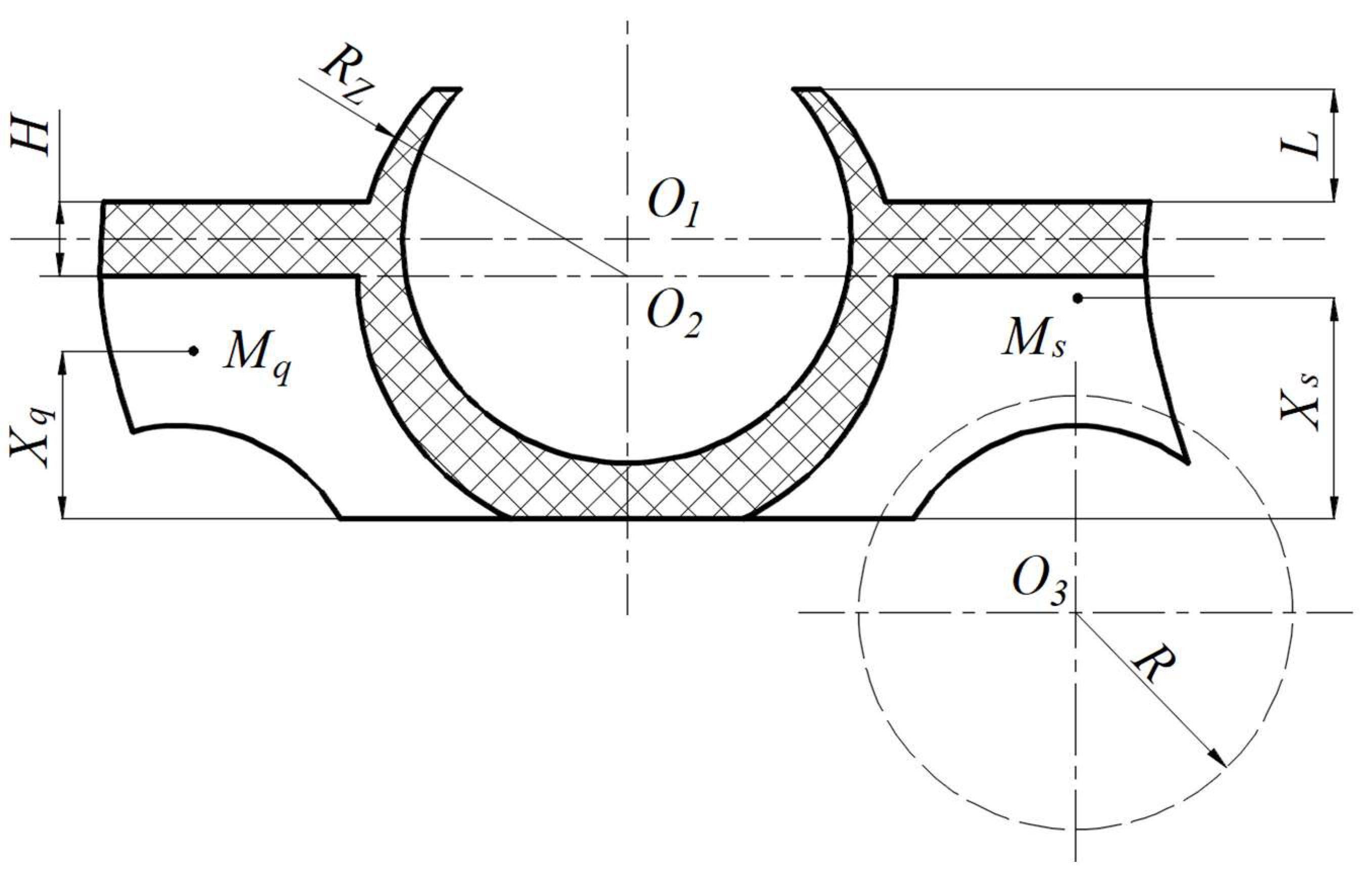
This study investigates the influence of cage eccentricity on cage strength and operational stability by modifying the cage structure through methods such as profiling the bottoms of adjacent pockets, grooving the side beams, and altering the claw length and external claw radius. Figure 2 illustrates the cross-section of a single crown-type cage pocket. In this figure, O1 denotes the center of the pocket sphere, O2 represents the center of the external claw sphere, and O3 indicates the center of the profiling sphere at the cage bottom (with an axial distance of 3 mm from the profiling sphere center to the cage bottom). Mq is the axial center of mass of the cage, derived from the centroid coordinates in 3D drawing software, while Ms is the axial geometric center of the cage, measured as half the cage width in the same software. The variables Xq and Xs represent the axial distances from the cage center of mass and geometric center to the cage bottom, respectively. Additionally, R denotes the profile radius, H indicates the side beam thickness, L refers to the claw length, and RZ signifies the claw radius. From the schematic in Figure 2, it is evident that while modifying the cage profile radius, side beam thickness, and claw radius keeps the axial geometric center Ms of the cage constant, it alters the axial center of mass Mq, resulting in a change in cage eccentricity. Conversely, changing the claw length affects both the axial geometric center Ms and the axial center of mass Mq, leading to a variation in cage eccentricity.

3. Deep Groove Ball Bearing Dynamics Model

3.1. Deep Groove Ball Bearing Coordinate System

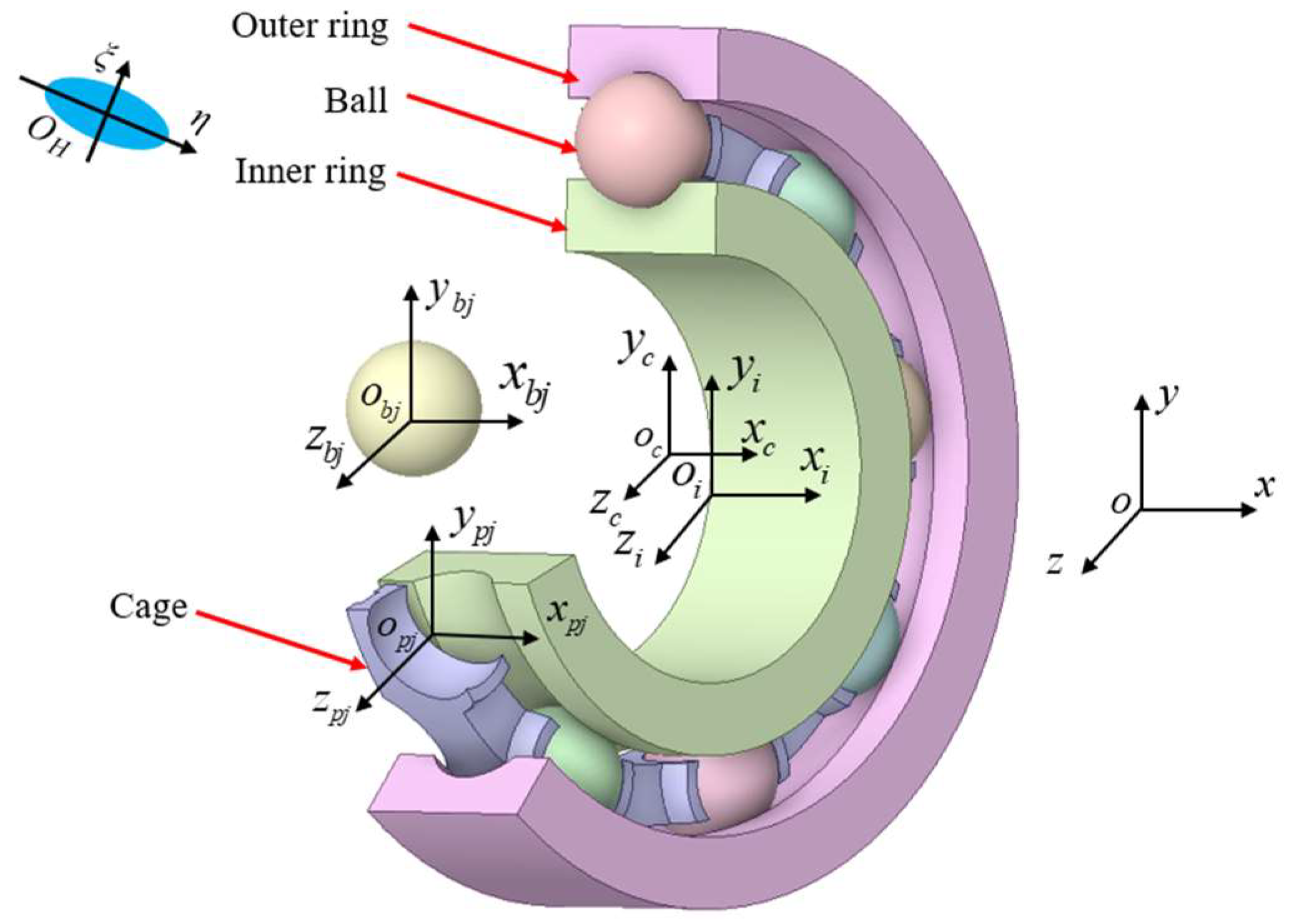
Rolling bearing dynamics is multi-body dynamics. To describe the motion of the bearing and its components, an inertial coordinate system and several local coordinate systems are selected for the ball bearing, as shown in Figure 3.
(1) Inertial coordinate system (o; x, y, z): The x-axis of this system coincides with the bearing centerline, the yz plane is parallel to the radial plane passing through the bearing center, the origin o is located at the center of the bearing outer ring. This system is fixed in space, and other coordinate systems are determined relative to it.
(2) Cage center coordinate system (oc; xc, yc, zc): The xc-axis of this system is consistent with the direction of the fixed coordinate system’s x-axis, the yczc plane is parallel to the radial plane passing through the cage center, the origin oc coincides with the geometric center of the cage. Initially, this system coincides with the inertial coordinate system (o; x, y, z); during bearing operation, it moves and rotates with the cage.
(3) Inner ring center of mass coordinate system (oi; xi, yi, zi): The xi-axis of this system is consistent with the direction of the fixed coordinate system’s x-axis, the yizi plane is parallel to the radial plane passing through the inner ring center, the origin oi coincides with the geometric center of the inner ring. Initially, this system coincides with the inertial coordinate system (o; x, y, z); during bearing operation, it moves and rotates with the inner ring.
(4) Ball center coordinate system (obj; xbj, ybj, zbj): The origin obj of this system is located at the geometric center of the cage pocket. The xbj-axis is consistent with the direction of the fixed coordinate system’s x-axis, the ybj-axis direction is from the bearing center towards the pocket center, the ybjzbj plane is parallel to the radial plane passing through the pocket center.
(5) Cage pocket center coordinate system (opj; xpj, ypj, zpj): The origin opj of this system is located at the geometric center of the ball. The xpj-axis is consistent with the direction of the fixed coordinate system’s x-axis, the ypj-axis direction is from the bearing center towards the ball center, the ypjzpj plane is parallel to the radial plane passing through the ball center.
(6) Contact surface coordinate system {OH; ξ, η}: The origin of the contact surface coordinate system is set at the center of the observed contact surface. The ξ-axis is the minor axis of the contact ellipse, pointing in the rolling direction of the contact bodies. The η-axis is the major axis of the contact ellipse, perpendicular to the rolling direction.

3.2. Interaction Between Cage and Balls

3.2.1. Normal Force Between Pocket and Ball

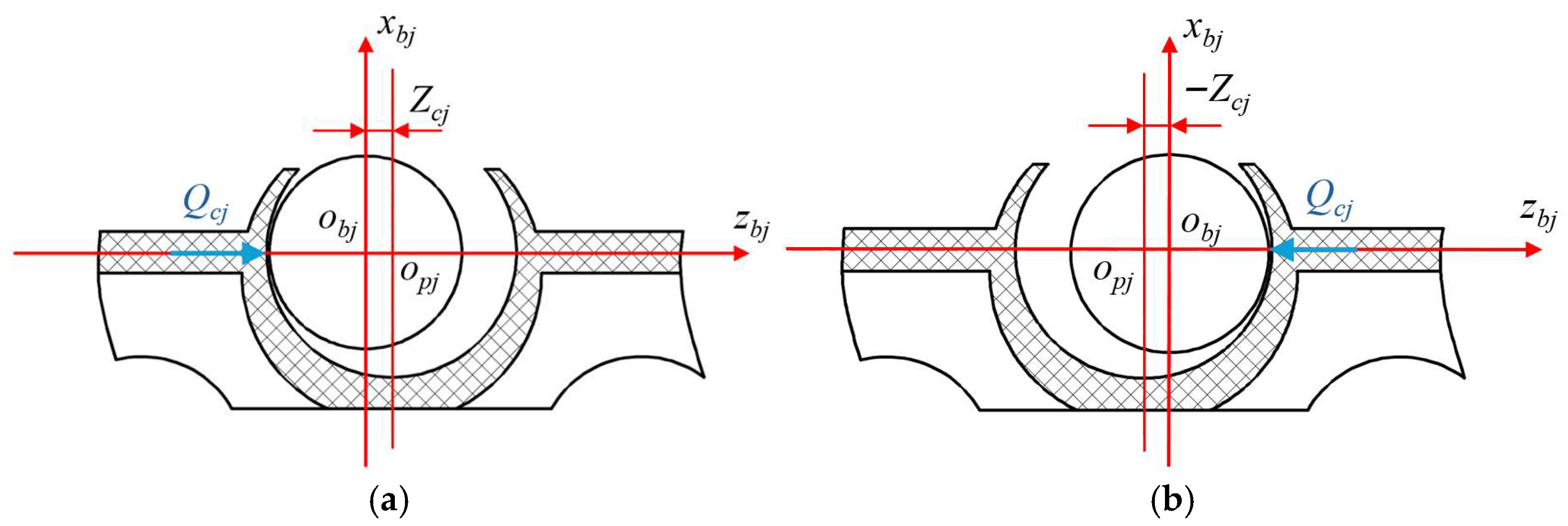
The normal force between the ball and the pocket is determined based on the position of the ball within the pocket. Figure 4 shows the cases where the pocket center op leads the ball center ob and where the pocket center op lags behind the ball center ob. This paper stipulates: when op leads, Zcj is positive; when op lags, Zcj is negative. When Zcj is positive, it indicates the cage pushes the ball; when Zcj is negative, it indicates the ball pushes the cage.
The normal force between the ball and the cage pocket Qcj:
Q c j = K c Z c j K c C p + K n Z c j C p 1.5 Z c j C p Z c j > C p
where Kc is a linear approximation constant determined by experimental data, for ball bearings: Kc = 11/Cp; Cp is the cage pocket clearance: Cp = 0.5(DpDw); Dp is the cage pocket diameter, take 11.56 mm; Dw is the ball diameter, take 11.112 mm. Kn is the load-deformation constant at the contact point between the steel ball and the cage.

3.2.2. Hydrodynamic Friction Force Between Pocket and Ball

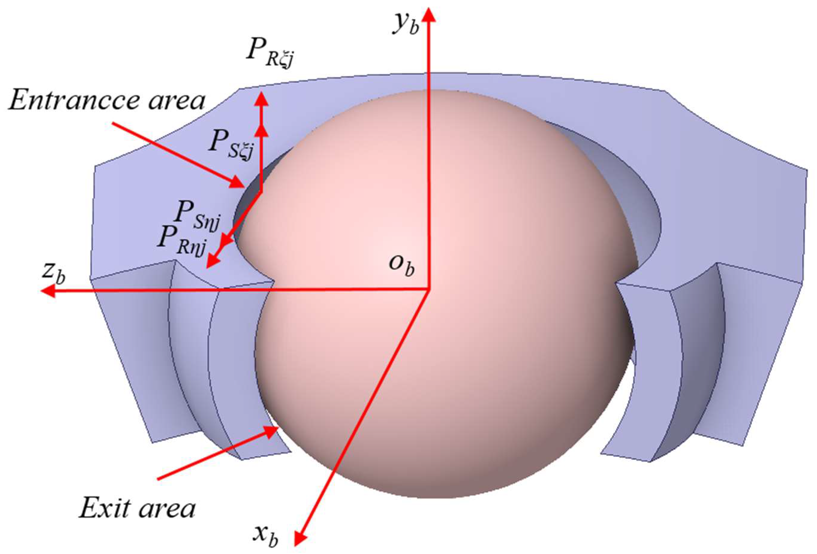
The fluid in the inlet zone of the contact surface, drawn into the contact surface by pumping action, generates rolling friction resistance PRξ(η)j and sliding friction resistance PSξ(η)j on the surface of the moving ball, as shown in Figure 5. Assume the contact surface center is at the intersection of the cage pocket surface and the cage pitch diameter.
Rolling friction force acting on the ball surface:
P R ξ j = 0.5 C O p j P ¯ R j cos θ p j
P R η j = 0.5 C O p j P ¯ R j R p ξ / R p η sin θ p j
Sliding friction force acting on the ball surface:
P S ξ j = P ¯ s j η 0 μ s p ξ j R p ξ R p η
P S η j = P ¯ s j η 0 μ s p η j R p ξ R p η
where
C O p j = η 0 μ p ξ j R p ξ R p η 3 + 2 k p 2 + μ p η j 2 3 + 2 k p 1 2 k p 1 / μ p ξ j 2
where μpξj is the lubricant entrainment velocity in the ξ direction between the ball and pocket surface; R is the effective radius of curvature in the ξ direction between the ball and pocket surface; R is the effective radius of curvature in the η direction between the ball and pocket surface; μpηj is the lubricant entrainment velocity in the η direction between the ball and pocket surface; μspξj is the relative sliding velocity in the ξ direction between the ball and pocket surface; μspηj is the relative sliding velocity in the η direction between the ball and pocket surface.

3.3. Flexible Body Dynamics Differential Equation of the Cage

Based on the deep groove ball bearing dynamics analysis in the literature [25], treating the deep groove ball bearing cage as a flexible body and using the modified Craig-Bampton substructure modal synthesis method, the flexible body dynamics differential equation of the deep groove ball bearing cage can be obtained via the Lagrange equation as:
M c ζ + M c ζ 1 2 M c ζ ζ T ζ + K ζ + D ζ + F g + Φ c ζ T λ = F c a g e
where
M c = M t t M t r M t m M t r T M r r M r m M t m T M r m T M m m
ζ = R Ω q l T
where Mc is the cage mass matrix, Mc′ is the time derivative of the mass matrix, subscripts t, r, m represent translational, rotational, and modal degrees of freedom, respectively; ζ, ζ′, ζ″ are the generalized coordinates of the flexible cage and their time derivatives, R is the displacement coordinate, Ω is the Euler angle coordinate, ql is the modal coordinate, l is the number of modal coordinates; D is the modal damping matrix of the flexible cage, a constant symmetric matrix, which can be represented by a diagonal matrix with modal damping ratios ci on the diagonal; K is the stiffness matrix of the flexible cage, a constant; Fg is the gravity force of the flexible cage; Φc is the geometric constraint condition of the flexible cage; λ is the Lagrange multiplier of the constraint equation.
Fcage is the generalized force on the cage, which can be expressed as:
F c a g e = F T T R F M T
where FT is the generalized translational force on the cage; TR is the generalized torque on the cage; FM is the generalized modal force on the cage. FT, TR, FM are expressed as:
F T = A F y 2 + F z 2
F y = j = 1 n F S η j F R η j cos ϕ j + F c j sin ϕ j + F c y
F z = j = 1 n F S η j F R η j sin ϕ j F c j cos ϕ j + F c z
T R = B j = 1 n F S η j F R η j D w 2 F c j d m 2 + M c x
F M = Φ T F T + Φ T A M c x
Equations (11)–(15): Фj is the position angle of the j-th ball; A is the Euler transformation matrix of the cage force point coordinate system relative to the global coordinate system; B is the transformation matrix of the resultant moment at the cage force point relative to the Euler angle coordinate system; Ф, Ф* are the modal participation factors for the translational and rotational degrees of freedom at the force point in the modal coordinate system, respectively.

3.4. Cage Vibration Acceleration Level

In the process of bearing dynamic analysis, the cage vibration acceleration level can usually be used to evaluate the operational stability of the cage. Its calculation method is shown in Equation (16):
V a l = 20 log 10 ( a r a 0 )
where Val is the cage vibration acceleration level, dB; ar is the actual acceleration of the cage’s center of mass, obtained from dynamic simulation, m/s2; a0 is the reference acceleration, taken as 9.81 m/s2.

4. Simulation Analysis

Based on the theory of rolling bearing dynamics and the differential equations governing flexible cage dynamics, secondary development was performed using dynamics simulation software, which facilitated parametric modeling and dynamic simulations. The flexible cage model was integrated into the established deep groove ball bearing model to replace the original rigid cage. Operating conditions were defined for simulation analysis to evaluate the strength and operational stability of the flexible cage under varying structural parameters. The simulation analysis was conducted based on the operating conditions of a specific new energy vehicle bearing, with a radial force of 2000 N and a rotational speed of 20,000 r/min. The simulation duration was set to 2 s, and the maximum results obtained during the final stable 1 s of bearing operation were extracted for analysis.

4.1. Flexibilization of the Crown-Type Cage

During high-speed operation, crown-type cages may experience fracture failure. This can occur due to inadequate lubrication or insufficient cooling, which causes the cage temperature to rise and leads to wear on the pocket holes and guide surfaces. In severely worn areas, micro-cracks may develop, and their propagation can ultimately result in cage fracture. Alternatively, fracture may occur due to structural weak points in the crown-type cage, such as the bottom of the pocket holes or the side beams between pockets. Under alternating stress, cracks may initiate and propagate, leading to cage failure. Cage strength characterizes its ability to resist plastic deformation or fracture. Therefore, conducting a strength analysis of the crown-type cage in high-speed deep groove ball bearings is of paramount importance. For deep groove ball bearings used in new energy vehicle motors, it is essential for the cage to possess characteristics such as lightweight design and low friction performance under high-speed conditions. These cages are predominantly constructed from lightweight materials, including nylon or reinforced plastics. During operation, the interactions between the cage and the balls and rings predominantly exhibit flexible behavior.
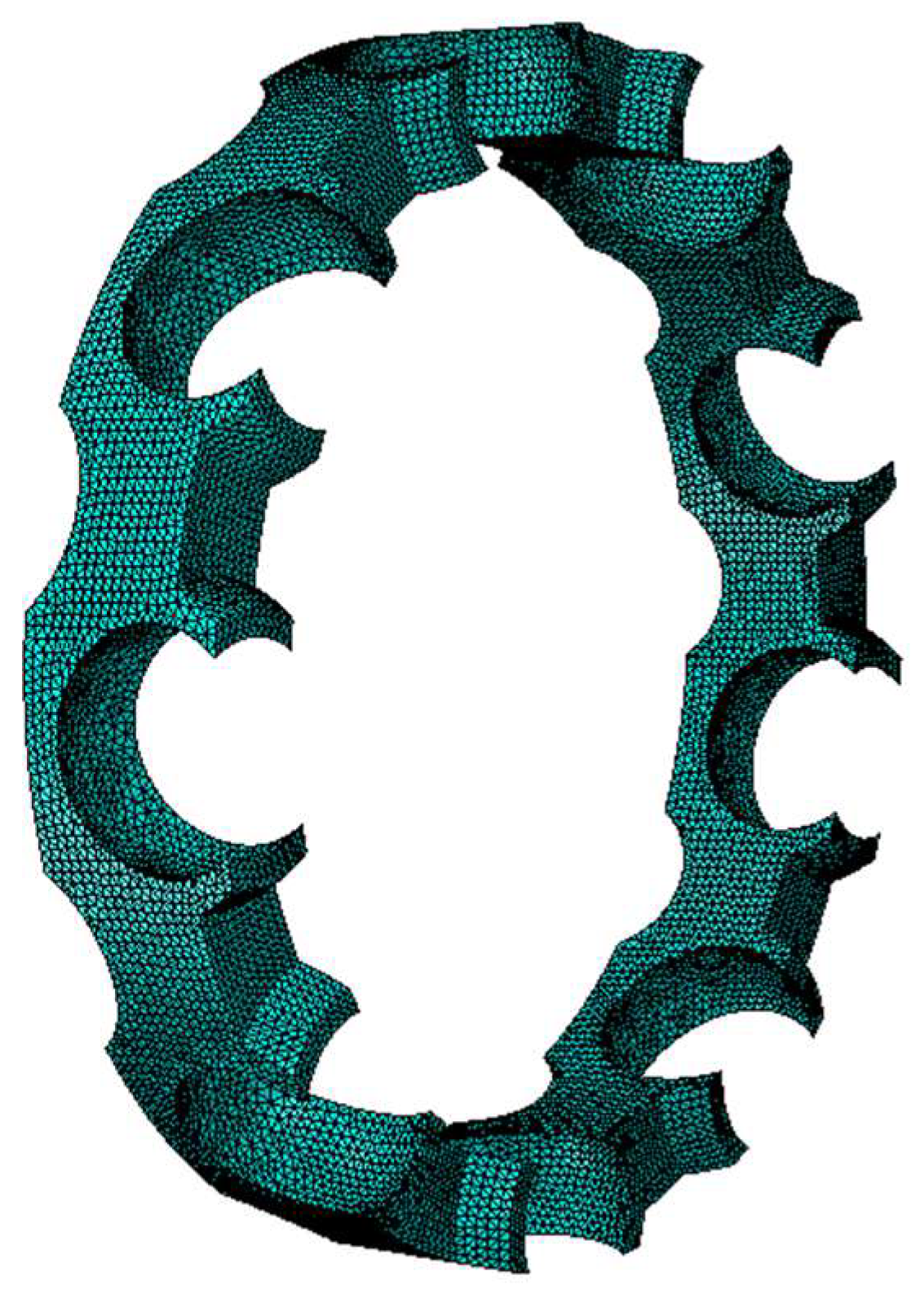
When conducting dynamic simulation analysis of bearings, a rigid cage cannot reflect the stress and deformation distribution on the cage during operation. The material of the crown-type cage differs from that of the inner ring, outer ring, and steel balls. During the operation of the bearing, the cage exhibits flexibility, while the other components remain rigid. By flexibilizing the crown-type cage and performing a rigid–flexible coupling simulation, the contact state between the cage and the steel balls, the strength of the cage, and the operational stability can be obtained more closely to reality. Consequently, Abaqus finite element software was employed to introduce flexibility into the crown-type cage. The process of flexibilization primarily involves assigning material properties, setting natural frequencies and modes, and performing meshing, as shown in Table 2. The resulting mesh is illustrated in Figure 6.

4.2. Flexible Cage Strength Analysis

Excessive deformation of the cage adversely impacts its guiding and separating functions for the rolling elements, thereby disturbing their motion trajectory, impeding normal rolling, and ultimately shortening the bearing’s service life. Such excessive equivalent stress can lead to material fatigue in the cage, which may result in fracture in severe cases. The magnitude of eccentricity varies with different structural parameters of the crown-type cage. The axial geometric center coordinate and the axial center of mass coordinate of the cage can be measured using 3D drawing software; the difference between these two coordinates represents the eccentricity. A secondary development program based on dynamic simulation software was employed to analyze the equivalent stress and maximum deformation of the crown-type cage under varying structural parameters.

4.2.1. Influence of Profile Radius R on Cage Strength

Table 3 shows the cage mass, axial geometric center position, center of mass position, and eccentricity size when the side beam thickness H = 2.3 mm, claw length L = 2.2 mm, and claw radius Rz = 7.5 mm, and the profile radius R varies from 5.0 mm to 6.0 mm. From Table 3, it can be seen that as the profile radius R increases from 5.0 mm to 6.0 mm, the cage eccentricity decreases from 0.947 mm to 0.693 mm.
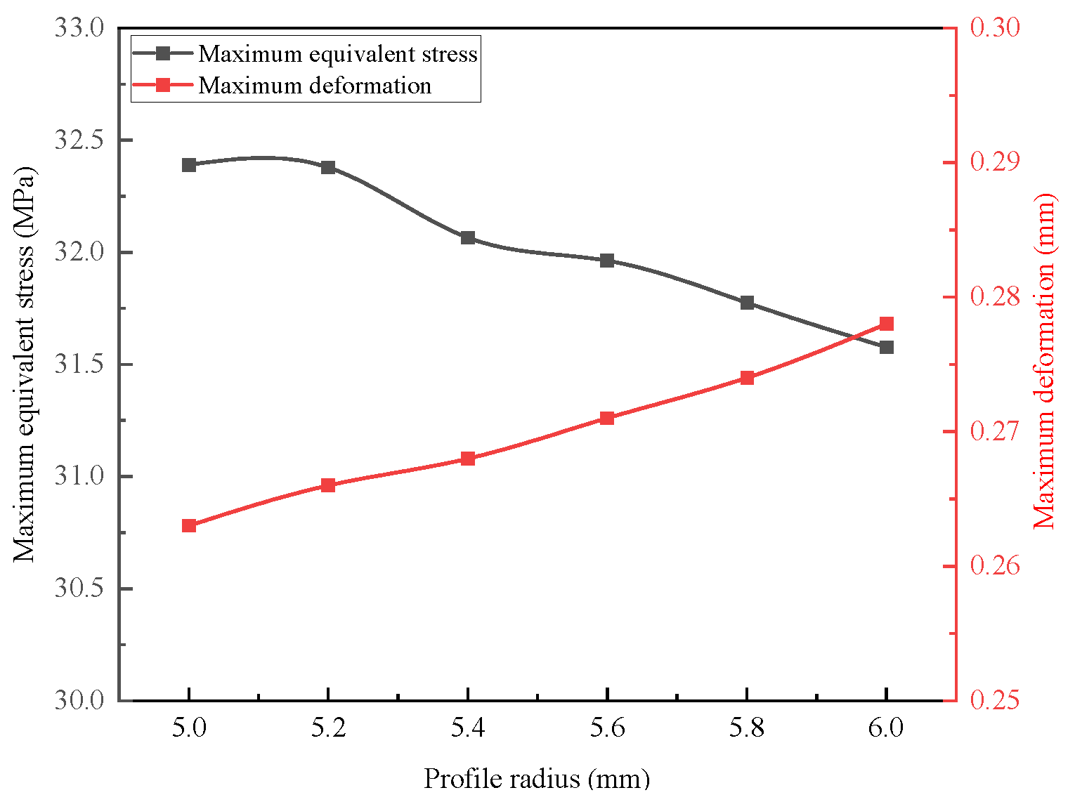
When the bearing operation is stable, the equivalent stress distribution and deformation on a single pocket of the flexible cage, with a profile radius of R = 5.0 mm, are illustrated in Figure 7. Figure 8 depicts the trend of equivalent stress and maximum deformation of the flexible cage as the profile radius increases, while maintaining constant structural parameters.
As shown in Figure 7, during stable bearing operation, the maximum deformation of the crown-type cage is 0.263 mm, occurring at the claw ends, where support is weaker, making it susceptible to significant deformation due to ball collision forces and its own centrifugal force. The equivalent stress of the crown-type cage is 32.39 MPa, located at the pocket bottom, where strength is comparatively lower, and is the primary site for cage fracture failure. Figure 8 indicates that as the profile radius increases, the equivalent stress in the cage decreases from 32.39 MPa to 31.58 MPa, while the deformation of the cage increases from 0.263 mm to 0.278 mm. This phenomenon occurs because, with an increasing profile radius, the cage eccentricity decreases, which shifts the contact position between the balls and the cage pockets closer to the claw ends, resulting in greater deformation at the claw ends and a reduction in centrifugal force, thereby decreasing the equivalent stress at the pocket bottom.

4.2.2. Influence of Side Beam Thickness H on Cage Strength

Table 4 shows the cage mass, axial geometric center position, center of mass position, and eccentricity size when the profile radius R = 5.8 mm, claw length L = 2.2 mm, and claw radius Rz = 7.5 mm, and the side beam thickness H varies from 1.5 mm to 2.5 mm. From Table 4, it can be seen that as the side beam thickness H increases from 1.5 mm to 2.5 mm, the cage eccentricity decreases from 0.7939 mm to 0.7379 mm.
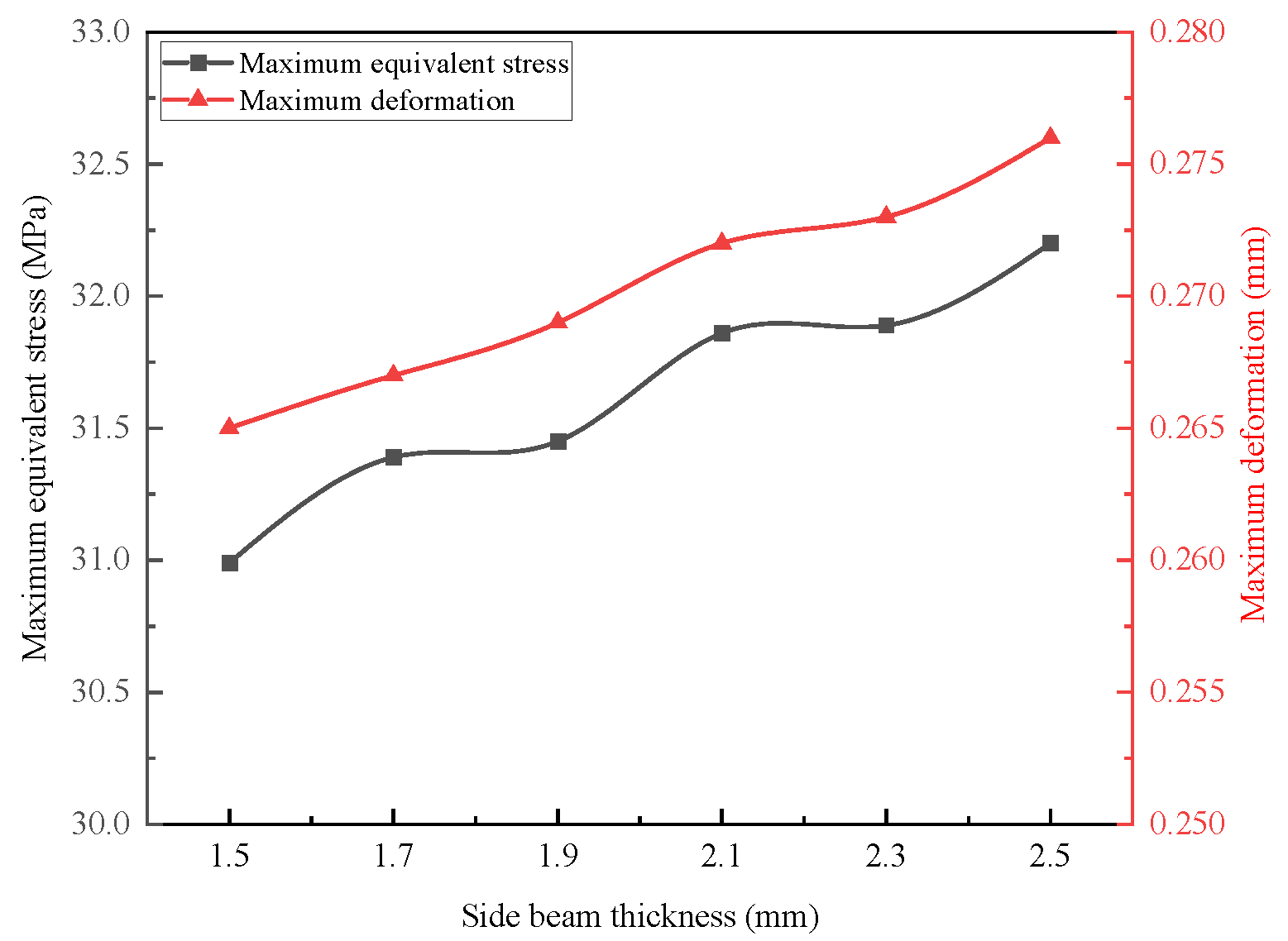
Figure 9 illustrates the variation trend of the equivalent stress and maximum deformation of the flexible cage as the thickness of the side beam increases, while keeping other structural parameters constant. As depicted in Figure 9, the equivalent stress of the cage rises from 30.99 MPa to 32.20 MPa, and the deformation of the cage increases from 0.265 mm to 0.276 mm with the increase in side beam thickness. This phenomenon occurs because the increase in side beam thickness leads to a decrease in cage eccentricity, which shifts the contact position between the balls and the cage pockets closer to the claw ends, thereby increasing deformation at those ends. Furthermore, as the side beam thickness increases, the centrifugal force acting on the cage also rises, resulting in an overall increasing trend in equivalent stress.

4.2.3. Influence of Claw Length L on Cage Strength

Table 5 shows the cage mass, axial geometric center position, center of mass position, and eccentricity size when the profile radius R = 5.8 mm, side beam thickness H = 1.5 mm, and claw radius Rz = 7.5 mm, and the claw length L varies from 2.0 mm to 3.0 mm. From Table 5, it can be seen that as the claw length L increases from 2.0 mm to 3.0 mm, the cage eccentricity increases from 0.7396 mm to 1.006 mm.
Figure 10 illustrates the variation trend of equivalent stress and maximum deformation of the flexible cage as the claw length increases, with other structural parameters held constant. As shown in Figure 10, the equivalent stress of the cage rises from 30.79 MPa to 33.49 MPa, while the deformation of the cage increases from 0.255 mm to 0.304 mm. This phenomenon occurs because an increase in claw length results in greater cage eccentricity, which shifts the contact position between the balls and the cage pockets closer to the pocket bottom and the centrifugal force acting on the cage escalates, leading to an increase in equivalent stress at the pocket bottom. Additionally, as the claw length increases, the support at the claw ends diminishes, rendering them more susceptible to deformation under ball impact, thereby resulting in increased cage deformation.

4.2.4. Influence of Claw Radius Rz on Cage Strength

Table 6 shows the cage mass, axial geometric center position, center of mass position, and eccentricity size when the profile radius R = 5.8 mm, side beam thickness H = 1.5 mm, and claw length L = 2.0 mm, and the claw radius Rz varies from 7.0 mm to 9.0 mm. From Table 6, it can be seen that as the claw radius Rz increases from 7.0 mm to 9.0 mm, the cage eccentricity decreases from 0.9308 mm to 0.2669 mm.
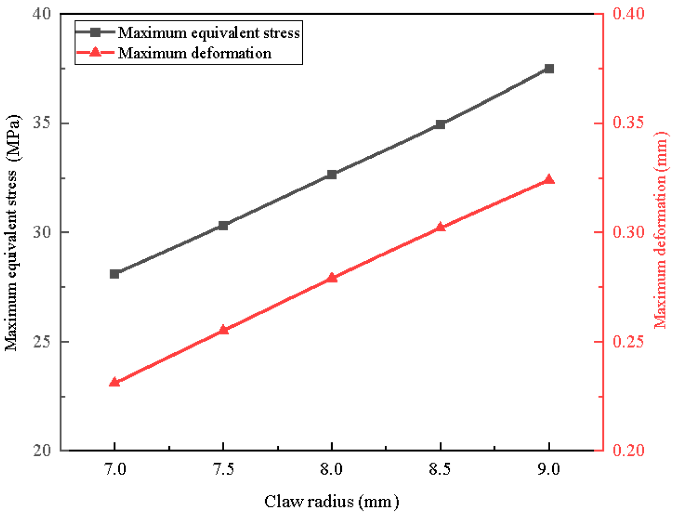
Figure 11 illustrates the variation trend of equivalent stress and maximum deformation of the flexible cage as the claw radius increases, with all other structural parameters held constant. As depicted in Figure 11, the equivalent stress of the cage rises from 28.11 MPa to 37.52 MPa, while the deformation of the cage increases from 0.231 mm to 0.324 mm. This phenomenon occurs because an increase in claw radius leads to a decrease in cage eccentricity, which brings the contact position between the balls and the cage pockets closer to the ends of the claws, thereby increasing deformation at these ends. Furthermore, as the claw radius increases, the centrifugal force exerted on the cage also rises, resulting in an increase in equivalent stress.

4.3. Flexible Cage Stability Analysis

Changes in the structural parameters of the cage not only affect its structural strength but also influence the operational stability of the cage during bearing operation. As a critical component of the bearing, the operational stability of the cage significantly impacts the service life of the bearing. A secondary development program utilizing dynamic simulation software was employed to analyze the collision forces between the balls and the cage, as well as the cage’s vibration amplitude and vibration acceleration levels under varying structural parameters.

4.3.1. Influence of Profile Radius R on Cage Operational Stability

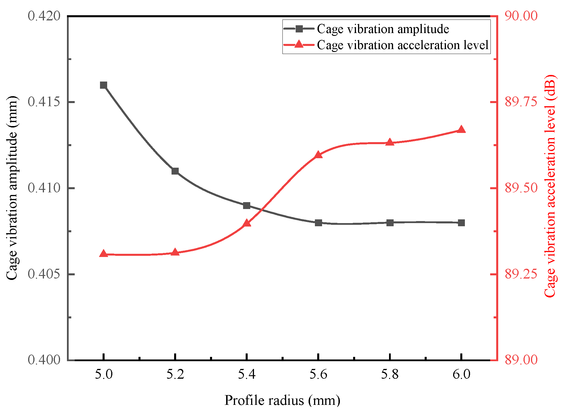
Figure 12 illustrates the trend of variation in the collision force between the balls and the cage as the profile radius increases, with all other structural parameters held constant. Similarly, Figure 13 depicts the trend of variation in both the cage vibration amplitude and the cage vibration acceleration level as the profile radius increases, while keeping other structural parameters constant. As indicated in Figure 12, when the profile radius increases from 5.0 mm to 6.0 mm, the cage eccentricity decreases, resulting in a reduction in the collision force between the balls and the cage from 5.50 N to 4.71 N. In reference to Figure 13, as the profile radius increases from 5.0 mm to 6.0 mm, the cage eccentricity also decreases, leading to a decrease in the cage vibration amplitude from 0.416 mm to 0.408 mm, while the cage vibration acceleration level rises from 89.308 dB to 89.669 dB. This phenomenon can be attributed to the fact that as the profile radius increases, the reduction in the collision force between the balls and the cage results in a decrease in the cage vibration amplitude. Concurrently, the decrease in cage eccentricity reduces the additional resistance torque caused by asymmetry, which in turn increases the effective value of cage acceleration, ultimately leading to an increase in the cage vibration acceleration level.

4.3.2. Influence of Side Beam Thickness H on Cage Operational Stability

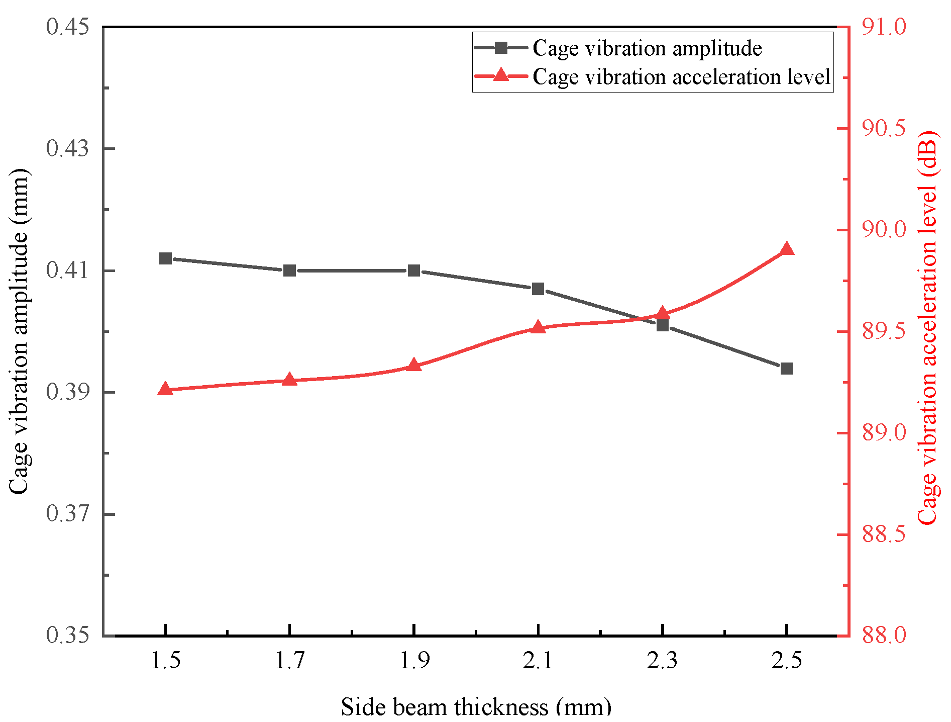
Figure 14 illustrates the variation trend of the collision force between the balls and the cage as the side beam thickness increases, with all other structural parameters held constant. Similarly, Figure 15 depicts the variation trend of the cage’s vibration amplitude and vibration acceleration level as the side beam thickness increases, with other structural parameters remaining unchanged. As shown in Figure 14, when the side beam thickness increases from 1.5 mm to 2.5 mm, the cage eccentricity decreases, resulting in a reduction in the collision force between the balls and the cage from 5.13 N to 4.73 N. According to Figure 15, with the same increase in side beam thickness, the cage eccentricity continues to decrease, leading to a reduction in cage vibration amplitude from 0.412 mm to 0.394 mm, while the cage vibration acceleration level rises from 89.211 dB to 89.901 dB. This phenomenon can be attributed to the fact that as the side beam thickness increases, the reduction in collision force between the balls and the cage contributes to a decrease in cage vibration amplitude. Concurrently, the decrease in cage eccentricity diminishes the additional resistance torque generated by asymmetry, resulting in an increase in the effective value of cage acceleration, which subsequently leads to an elevation in the cage vibration acceleration level.

4.3.3. Influence of Claw Length L on Cage Operational Stability

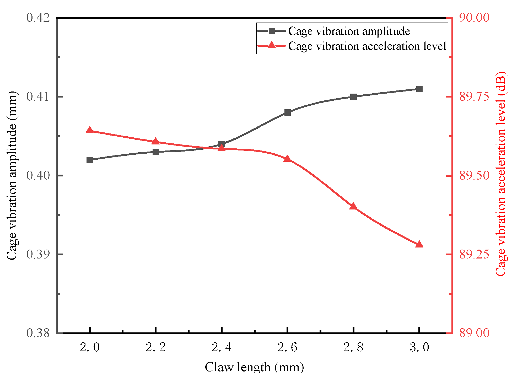
Figure 16 illustrates the trend of collision force variation between the balls and the cage as the claw length increases, while other structural parameters remain constant. Similarly, Figure 17 depicts the trend of cage vibration amplitude and acceleration level as the claw length increases, with other structural parameters held constant. As indicated in Figure 16, when the claw length increases from 2.0 mm to 3.0 mm, the cage eccentricity also increases, resulting in an increase in the collision force between the balls and the cage from 4.71 N to 5.19 N. According to Figure 17, with the claw length increasing from 2.0 mm to 3.0 mm, the cage eccentricity rises, leading to an increase in cage vibration amplitude from 0.394 mm to 0.412 mm. Conversely, the cage vibration acceleration level decreases from 89.642 dB to 89.280 dB. This phenomenon can be attributed to the fact that as the claw length increases, the cage eccentricity increases, which in turn raises the collision force between the balls and the cage, thereby increasing the cage vibration amplitude. At the same time, the increase in cage eccentricity results in a greater additional resistance torque due to asymmetry, which decreases the effective value of cage acceleration, ultimately causing a reduction in the cage vibration acceleration level.

4.3.4. Influence of Claw Radius Rz on Cage Operational Stability

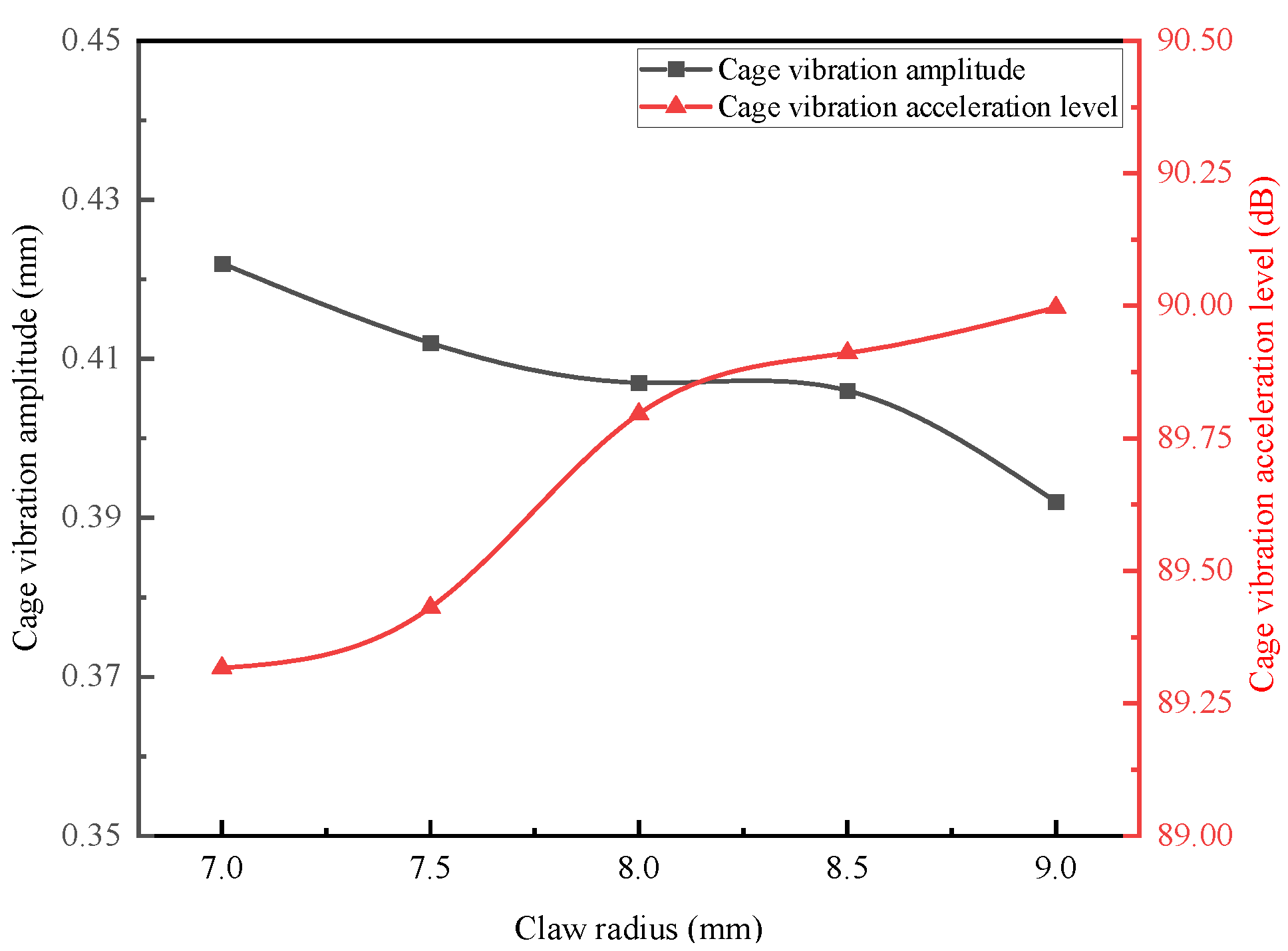
Figure 18 illustrates the trend of collision force variations between the balls and the cage as the claw radius increases, while maintaining constant values for other structural parameters. Similarly, Figure 19 depicts the trend of both cage vibration amplitude and cage vibration acceleration level as the claw radius increases under the same constant conditions. As indicated in Figure 18, when the claw radius increases from 7.0 mm to 9.0 mm, the cage eccentricity decreases, resulting in a reduction in the collision force between the balls and the cage from 5.48 N to 4.50 N. In Figure 19, it is observed that with the claw radius increasing from 7.0 mm to 9.0 mm, the cage eccentricity decreases, leading to a decrease in cage vibration amplitude from 0.422 mm to 0.392 mm, while the cage vibration acceleration level rises from 89.417 dB to 89.997 dB. This phenomenon occurs because the increase in claw radius reduces cage eccentricity, which in turn diminishes the collision force between the balls and the cage, thereby decreasing the cage vibration amplitude. Concurrently, the reduction in cage eccentricity lowers the additional resistance torque caused by asymmetry, resulting in an increase in the effective value of cage acceleration, which subsequently elevates the cage vibration acceleration level.

5. Conclusions

By modifying the structural parameters of the crown-type cage, including profile radius, side beam thickness, claw length, and claw radius, its eccentricity can be effectively adjusted. Based on the simulation analysis results from Section 4, which involved flexibilizing the crown-type cage and integrating it with other rigid bearing components for dynamic simulation, the following conclusions can be drawn:
  • Stress and Deformation Distribution: The claw ends of the crown-type cage pockets are particularly vulnerable to deformation, with the maximum equivalent stress occurring at the bottom of the pocket. This location is critical, as it represents the primary site for potential cage fracture failure.
  • Influence of Eccentricity on Strength: A reduction in cage eccentricity leads to a decrease in equivalent stress, while simultaneously increasing the maximum deformation of the cage. For example, when the profile radius R increases from 5.0 mm to 6.0 mm, the eccentricity decreases by approximately 27%, resulting in an approximate 2.5% reduction in equivalent stress. However, this change also leads to a maximum deformation increase of about 5.7%. These findings indicate that in the pursuit of a lightweight cage design, structural parameters should be optimized according to specific functional requirements, carefully balancing the priorities of low stress and minimal deformation in relation to cage eccentricity.
  • Influence of Centrifugal Force: An analysis of the side beam thickness and claw radius indicates that the strength of the cage is significantly affected not only by eccentricity but also by the centrifugal force exerted by the cage itself. The equivalent stress is observed to increase with the centrifugal force. For instance, when the side beam thickness (H) is increased from 1.5 mm to 2.5 mm—resulting in an increase in mass and centrifugal force—the eccentricity decreases; however, the equivalent stress still rises by approximately 3.9%.
  • Influence of Eccentricity on Stability: The eccentricity of the crown-type cage significantly influences its operational stability. A decrease in cage eccentricity leads to a reduction in the collision force between the balls and the cage, as well as a decrease in the cage’s vibration amplitude. However, this reduction in eccentricity also results in an increase in the vibration acceleration level due to a decrease in the additional resistance torque caused by axial asymmetry. For instance, an increase in the profile radius (R) results in the ball–cage collision force decreasing from 5.50 N to 4.71 N (approximately a 14.4% decrease), the cage vibration amplitude decreasing from 0.416 mm to 0.408 mm, and the cage vibration acceleration level increasing from 89.308 dB to 89.669 dB. Therefore, from a stability perspective, it is not necessarily true that smaller eccentricity is always better; a targeted design is required based on functional requirements, whether aiming for lower collision force/amplitude or lower vibration acceleration.
The influence of crown-type cage eccentricity on its strength and operational stability is non-monotonic and complex, involving multiple interrelated and sometimes contradictory performance indicators, such as stress, deformation, collision force, and vibration. When designing the structure of the crown-type cage, it is essential not to focus solely on reducing friction or achieving lightweight designs that may result in excessively large or small cage eccentricities. Instead, one should clarify the specific operating conditions and performance priorities to conduct a comprehensive trade-off and optimization of various structural parameters.

Author Contributions

Conceptualization, H.Y. and J.Z.; writing—original draft preparation, J.Z. and R.Z.; formal analysis, J.Z. and Z.S.; writing—review and editing, H.Y.; project administration, H.Y. and J.Z.; visualization, J.Z. and H.D.; funding acquisition, H.Y. All authors have read and agreed to the published version of the manuscript.

Funding

This research received no external funding.

Data Availability Statement

The data used to support the findings of this study are available from the corresponding author upon request.

Conflicts of Interest

The authors declare no conflicts of interest.

References

  1. Xu, J.; Yang, L.; Li, J.; Yu, X.K.; Yin, Y.J. Effect of Cage Pocket Geometry on Dynamic Friction Torque of High—Speed Ball Bearings. J. Bear. 2015, 7, 34–36. [Google Scholar]
  2. Ye, Z.H.; Li, W.; Qu, X.J.; Xiong, Z.G. Effect of Elliptical Pocket on Cage Dynamic Performance of High Speed Ball Bearings. J. Mech. Des. Manuf. 2016, 6, 184–187+191. [Google Scholar]
  3. Zheng, H.T.; Li, Q.L.; Yin, Y.J.; Wei, L.; Li, D.Y.; Niu, Q.B. Analysis of Impact Load Between Bearing Ball and Retainer Based on ADAMS. J. Mech. Elect. Eng. Technol. 2019, 48, 33–35. [Google Scholar]
  4. Choe, B.; Lee, J.; Jeon, D.; Lee, Y. Experimental Study on Dynamic Behavior of Ball Bearing Cage in Cryogenic Environments, Part I: Effects of Cage Guidance and Pocket Clearances. J. Mech. Syst. Signal Proc. 2019, 115, 545–569. [Google Scholar] [CrossRef]
  5. Choe, B.; Kwak, W.; Jeon, D.; Lee, Y. Experimental Study on Dynamic Behavior of Ball Bearing Cage in Cryogenic Environments, Part II: Effects of Cage Mass Imbalance. J. Mech. Syst. Signal Proc. 2019, 116, 25–39. [Google Scholar] [CrossRef]
  6. Hu, L.; Pueh, L.H.; Wang, D.; Wang, Z. Fatigue Failure of High Precision Spindle Bearing Under Extreme Service Conditions. J. Eng. Fail. Anal. 2024, 158, 107951. [Google Scholar] [CrossRef]
  7. Man, W.W.; Zhang, W.H.; Zheng, Y.W.; Deng, S.E. Influence on Traction Characteristics of Lubricating Oil on Motion Stability for Cages in High Speed Angular Contact Ball Bearings. J. Bear. 2017, 11, 31–37. [Google Scholar]
  8. Li, T.; Yang, L.Y.; Liu, D.L.; Zhou, M.; Jin, C. Deformation and Modal Analysis of Plastic Cage Lock of Ball Bearing. J. Coal Mine Mach. 2020, 41, 82–84. [Google Scholar]
  9. Ma, S.J.; Tian, C.; Yang, C.; Yan, K.; Lenci, S.; Hong, J. New Bearing Model with Flexible Cage and Study of Dynamic Behavior under Variable-speed. Mech. Syst. Signal Process. 2024, 208, 111045. [Google Scholar] [CrossRef]
  10. Wang, M.K.; Yan, K.; Tang, Q.; Guo, J.D.; Zhu, Y.S.; Hong, J. Dynamic Modeling and Properties Analysis for Ball Bearing Driven by Structure Flexible Deformations. Tribol. Int. 2023, 179, 108163. [Google Scholar] [CrossRef]
  11. Zhang, H.; Lei, X.L.; He, Y. The Effect of Geometric and Working Parameters on Dynamic Performance of Flexible Cages on Bearings. J. Flight Control Detect. 2021, 4, 73–79. [Google Scholar]
  12. Zhao, D.T.; Hong, J.; Yan, K.; Zhao, Q.Q.; Fang, B. Dynamic Interaction between the Rolling Element and Cage of Rolling Bearing Considering Cage Flexibility and Clearance. Mech. Mach. Theory 2022, 174, 104905. [Google Scholar] [CrossRef]
  13. Liu, Y.Q.; Chen, Z.G.; Tang, L.; Zhai, W.M. Skidding Dynamic Performance of Rolling Bearing with Cage Flexibility Under Accelerating Conditions. Mech. Syst. Signal Proc. 2021, 150, 107257. [Google Scholar] [CrossRef]
  14. Yao, T.Q.; Xie, W.; Tan, Y. Flexible Multi-Body Dynamics Analysis on Cage of Angular Contact Ball Bearings. China Mech. Eng. 2014, 25, 117–122. [Google Scholar]
  15. Sadeghi, F.; Weinzapfel, N. A Discrete Element Approach for Modeling Cage Flexibility in Ball Bearing Dynamics Simulations. J. Tribol. 2009, 131, 021102. [Google Scholar] [CrossRef]
  16. Ma, X.M.; Wang, R.D.; Zhu, Y.T.; Li, Y.F.; Shi, L.W. Dynamic Performance Analysis of Drive Motor Bearing of New Energy Vehicle. J. Harbin Bearing 2022, 43, 3–11+21. [Google Scholar]
  17. Ashtekar, A.; Sadeghi, F. A New Approach for Including Cage Flexibility in Dynamic Bearing Models by Using Combined Explicit Finite and Discrete Element Methods. J. Tribol. 2012, 134, 041502. [Google Scholar] [CrossRef]
  18. Wang, M.K.; Yan, K.; Liu, Z.T.; Chen, F.; Hong, J. Transient Collision Behavior and Cage Instable Whirling Mechanism in Ball Bearings: Modeling Approach and Properties Investigation. Tribol. Int. 2023, 185, 108497. [Google Scholar] [CrossRef]
  19. Su, Y.; Zhang, J.Q.; Zhang, W. Theoretical and Experimental Approaches for Flexible Cage Dynamic Characteristics of Four-point Contact Ball Bearing Considering Multi-point Contact Behaviors. Mech. Syst. Signal Process. 2025, 223, 111929. [Google Scholar]
  20. Xie, P.F.; Su, M.; Jiang, Y.H.; Liang, X.D.; Deng, S.E. Dynamic Performance Analysis on Angular Contact Ball Bearing with Two-piece Ring Based on ADAMS. J. Bear. 2010, 8, 1–4+9. [Google Scholar]
  21. Yao, T.Q.; Wang, L.H.; Liu, X.B.; Huang, Y.Y. Multibody Dynamics Simulation of Thin-Walled Four-Point Contact Ball Bearing with Interactions of Balls, Ring Raceways and Crown-Type Cage. Multibody Syst. Dyn. 2020, 48, 337–372. [Google Scholar] [CrossRef]
  22. Meng, D.Z.; Wang, Y.J.; Gao, P.Y.; Liu, L. Transient Dynamic Characteristics Analysis and Deformation Research of Thin-walled Ball bearings. J. Constr. Mach. Equip. 2021, 52, 36–42+9. [Google Scholar]
  23. Yang, H.S.; Liu, Q.; Deng, S.E. Dynamic Characteristic Analysis of Angular Contact Ball Bearings with Two-piece Inner Rings in Aero-Engine Main Shafts Under Unsteady-State Conditions. Lubricants 2025, 13, 249. [Google Scholar] [CrossRef]
  24. Zhang, W.H.; Du, S.J.; Tian, H.; Huang, L. Cage Strength Analysis and Improvement of High-Speed Deep Groove Ball Bearings. Machines 2025, 13, 241. [Google Scholar] [CrossRef]
  25. Jia, X.F.; Zhang, W.H.; Zhao, B.H.; Cui, Y.C.; Deng, S.E. Influence of Structural Parameters of Deep Groove Ball Bearing Crown Cage on Its Performance. J. Bear. 2021, 12, 13–19. [Google Scholar]
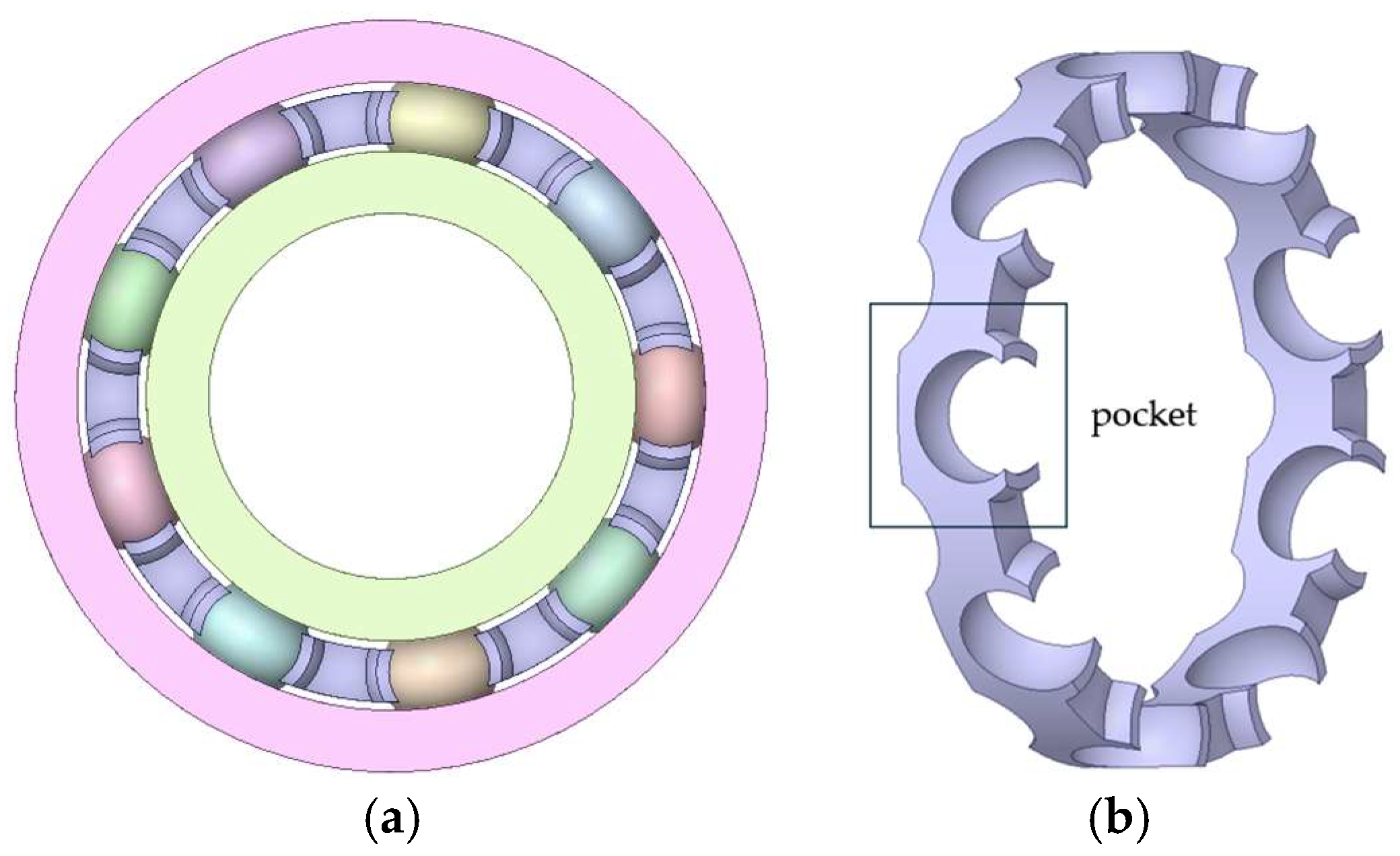
Figure 1. Geometric Structure: (a) Deep groove ball bearing geometric structure; (b) Crown-type cage geometric structure.
Machines 13 00991 g001
Figure 2. Schematic diagram of a single cage pocket cross-section.
Machines 13 00991 g002
Figure 3. Bearing Coordinate System.
Machines 13 00991 g003
Figure 4. Position relationship between ball center and cage pocket center: (a) op leads; (b) op lags.
Machines 13 00991 g004
Figure 5. Geometric configuration of ball–pocket contact surface.
Machines 13 00991 g005
Figure 6. Meshing of the flexible cage.
Machines 13 00991 g006
Figure 7. Deformation and equivalent stress on a single flexible cage pocket: (a) Deformation result on a single flexible cage pocket; (b) Equivalent stress result on a single flexible cage pocket.
Machines 13 00991 g007
Figure 8. Cage maximum equivalent stress and maximum deformation under different profile radii.
Machines 13 00991 g008
Figure 9. Cage maximum equivalent stress and maximum deformation under different side beam thicknesses.
Machines 13 00991 g009
Figure 10. Cage maximum equivalent stress and maximum deformation under different claw lengths.
Machines 13 00991 g010
Figure 11. Cage maximum equivalent stress and maximum deformation under different claw radii.
Machines 13 00991 g011
Figure 12. Ball–cage collision force under different profile radii.
Machines 13 00991 g012
Figure 13. Cage vibration amplitude and acceleration level under different profile radii.
Machines 13 00991 g013
Figure 14. Ball–cage collision force under different side beam thicknesses.
Machines 13 00991 g014
Figure 15. Cage vibration amplitude and acceleration level under different side beam thicknesses.
Machines 13 00991 g015
Figure 16. Ball–cage collision force under different claw lengths.
Machines 13 00991 g016
Figure 17. Cage vibration amplitude and acceleration level under different claw lengths.
Machines 13 00991 g017
Figure 18. Ball–cage collision force under different claw radii.
Machines 13 00991 g018
Figure 19. Cage vibration amplitude and acceleration level under different claw radii.
Machines 13 00991 g019
Table 1. Bearing Material Parameters.
ComponentMaterialDensity (kg/m3)Elastic Modulus (GPa)Poisson’s Ratio
Inner RingGCr1578102080.30
Outer RingGCr1578102080.30
BallGCr1578102080.30
CageNylon 6611408.30.28
Table 2. Crowned Cage Flexibilization Settings.
DensityElastic ModulusPoisson’s RatioNatural FrequenciesNumber of ModesMeshing MethodMinimum Mesh Size
1140 kg/m38.3 GPa0.283030Tetrahedral0.02 mm
Table 3. Cage Eccentricity under Different Profile Radii.
Profile Radius R/mmMass/gGeometric Center Pos./mmCenter of Mass Pos./mmEccentricity/mm
5.03.6015.1854.2380.947
5.23.5495.1854.28370.9013
5.43.4935.1854.33640.8486
5.63.4335.1854.38390.8011
5.83.3695.1854.43880.7462
6.03.3015.1854.4920.693
Table 4. Cage Eccentricity under Different Side Beam Thicknesses.
Side Beam Thickness H/mmMass/gGeometric Center Pos./mmCenter of Mass Pos./mmEccentricity/mm
1.53.2855.1854.39110.7939
1.73.3065.1854.40450.7805
1.93.3265.1854.41730.7677
2.13.3475.1854.42840.7566
2.33.3695.1854.43880.7462
2.53.3905.1854.44710.7379
Table 5. Cage Eccentricity under Different Claw Lengths.
Claw Length L/mmMass/gGeometric Center Pos./mmCenter of Mass Pos./mmEccentricity/mm
2.03.2605.0854.34540.7396
2.23.2855.1854.39110.7939
2.43.3105.2854.43710.8479
2.63.3355.3854.48390.9011
2.83.3605.4854.53140.9536
3.03.3605.6854.5791.006
Table 6. Cage Eccentricity under Different Claw Radii.
Profile Radius R/mmMass/gGeometric Center Pos./mmCenter of Mass Pos./mmEccentricity/mm
7.03.1375.0854.15420.9308
7.53.2605.0854.34430.7407
8.03.3795.0854.51620.4588
8.53.4975.0854.67340.4116
9.03.6135.0854.81810.2669
Disclaimer/Publisher’s Note: The statements, opinions and data contained in all publications are solely those of the individual author(s) and contributor(s) and not of MDPI and/or the editor(s). MDPI and/or the editor(s) disclaim responsibility for any injury to people or property resulting from any ideas, methods, instructions or products referred to in the content.