Abstract
Planetary gear trains offer numerous advantages over traditional gear systems, including high efficiency, the ability to handle large torque loads, and significant reductions in mass and size for the same torque capacity. However, their relatively complex design necessitates the use of optimization techniques to identify the most suitable configurations for specific applications. A key requirement for effective optimization is a mathematical model that accurately captures the essential operational characteristics of the system. Moreover, the optimization process must account for multiple, often conflicting, objectives. This paper focuses on the multicriteria optimization of a three-stage planetary gear train intended for use in a road vehicle winch. The development of the optimization model involves defining the objective functions, decision variables, and constraints. Optimization criteria were based on the following characteristics: overall volume, mass, transmission efficiency, and the production costs of the gear pairs. In addition to identifying the group of solutions that are Pareto optimal, the model employs the weighted coefficient method to select a single optimal solution from this set. The selected solution is then analyzed through simulation to assess potential gear failure scenarios. By combining optimization techniques with simulation and contact analysis, this study contributes to improving the reliability of planetary gear transmissions.
1. Introduction
Gears represent one of the most widely utilized mechanical components for power transmission across a broad range of machines [1,2], thanks to their high efficiency, reliability, compact design, and ease of integration into specific applications. Numerous studies have explored different gear-related issues, such as material properties [3], health monitoring and diagnostics [4], specific applications [5], wear resistance improvement [6], gear dynamic reliability [7], fatigue life of gears [8,9], wear load capacity [10], and new concepts of gears [11].
Planetary gear trains offer numerous advantages over traditional gear systems, including mass and size reductions, compactness, high efficiency, and the ability to handle large torque [12,13,14]. They are widely used in single-stage and compound gear trains [15], automobile transmissions, industrial drives, rotorcraft, wind turbines [12,16] and others. Xu et al. [16] presented the analysis of complex planetary gearboxes used in road vehicles, while Kalmaganbetov et al. [17] dealt with the selection of optimal layout variants for light electric vehicle main gearboxes. Owing to their high transmission efficiency and compact structural configuration, planetary gear trains are frequently used as primary mechanisms for torque amplification and speed reduction in electric vehicle drivetrains [18,19], as multipliers in wind energy conversion systems [20,21].
Optimization in engineering often involves multi-objective problems with conflicting goals. Real-world uncertainties, such as material properties and manufacturing errors, must be accounted for, as emphasized by Xu et al. [22]. Gear train optimization is a particularly complex and computationally demanding process [23,24]. To meet modern demands for efficiency and reliability, key objectives include minimizing size, weight, and power loss while maximizing service life. Various methods have been proposed. A group of authors [25,26,27] presented multi-objective strategies for optimizing gear tooth profiles and performance. Abderazek et al. [26] used an adaptive mixed differential evolution algorithm to optimize the spur gear profile. Maputi and Arora [28] applied the NSGA-II algorithm to the multi-objective optimization of a two-stage spur gearbox, enabling the identification of Pareto-optimal solutions. Wang [29] worked on gear noise reduction through helical gear modification. Artoni [30] proposed an algorithmic framework that integrates deterministic multi-objective techniques with a global direct-search strategy to achieve globally optimal solutions. Patil et al. [31] optimized a two-stage helical gearbox under constraints, including bending stress, pitting, and tribological limitations. Despite a high risk of wear, their results show significant power loss reduction through multi-objective optimization.
Planetary gear trains (PGTs) are well-suited for multi-objective optimization, though their complexity limits generalization. Arnaudow and Karaivanov [32] analyzed transmission ratio, internal power flow, and efficiency in complex PGTs. Yaw and Chong [33] proposed a hybrid optimization using genetic algorithms and artificial immune systems for volume reduction. Sedak and Rosić [34,35] discussed efficiency improvements via simulations, and introduced a hybrid algorithm for optimizing complex gear systems. Daoudi et al. [36] explored design goals, such as short center distance, low weight, and high efficiency using traditional and genetic algorithms. Čabala and Jadlovsky [37] explored AI methods combined with conventional approaches to optimize production.
Checks of various quality criteria by means of simulation are an essential prerequisite for the assessment of the overall design quality. Tooth profile modification reduces transmission errors, as shown by Lee et al. [38], who applied the Peak-to-Peak Transmission Error (PPTE) method for this purpose. Fiausch [39] showed that machining quality impacts vibration and noise, while Parab et al. [40] reiterated that plastic gears reduce noise but under higher loads, the transmission error in plastic gears increases more substantially than with metal gears. Factors such as speed and load affect performance [41,42], as do misalignments and tolerances [43].
This paper aims to contribute to the body of knowledge on optimization of PGTs by offering an approach to the multicriteria optimization procedure for a three-stage planetary gear train used in a road vehicle winch to return the vehicle back on the road. Key features, such as the reduction in overall dimensions and mass, an increase in torque and reduction in production costs, are to be considered in the optimization process. The optimization process will be conducted by means of the original PLANGEARS software developed by the authors of the paper, a numerical tool that enables techno-economic optimization through a multi-objective mathematical model. This tool was selected due to the adaptation of the software to this type of transmission with objective functions that can fully define the transmission, and the possibility of prioritizing functions according to the specific operating conditions of the transmission.
Additional checks related to the identification of failure risks, vibrations, and noise are to be performed to validate the Pareto-based conceptual design. This will primarily include a contact analysis for each stage of the considered PGT to assess transmission error and load distribution.
In summary, unlike most previous studies that concentrated on single-stage gear trains or isolated optimization objectives, this work focuses on a three-stage planetary gear train for a practical winch application. The proposed methodology, implemented through the dedicated PLANGEARS software version 3.0 and validated by transmission error, load distribution, vibration, and noise analyses, provides a more comprehensive and application-oriented framework.
2. Methodology
Optimization, defined as the process of searching for the best solutions, enhances the quality and reliability of power transmissions. Similar to any other engineering process, optimization must have a clearly defined objective. In this context, the objective must be specified unambiguously and in quantitative terms, allowing for a direct comparison of the solutions obtained and the selection of the most suitable one. The optimization objective is formulated through the objective function, while the operational conditions of the system are represented by a corresponding set of constraints. The solution of such an optimization problem requires the selection of an appropriate method, whereby the problem formulation must also satisfy the formal mathematical requirements inherent to the chosen method.
The optimization of gear transmissions constitutes a particularly challenging task due to the inherent characteristics of the mathematical model that describes their behavior. The mathematical formulation of technical system behavior is highly complex, even in the case of relatively simple systems. This complexity arises from the necessity to account for a large number of influencing factors, whose effects are described by intricate mathematical expressions. The possibility of reducing the number of relevant factors is limited and depends largely on a comprehensive understanding of the system’s nature and on the designer’s ability to accurately assess the significance of each factor. In any case, the mathematical model of gear transmission behavior remains highly complex, typically characterized by nonlinear, nondifferentiable, and discontinuous functions of varying variables.
Formulating a mathematical model represents the first step in the search for an optimal solution.
The mathematical model on which the PLANGEARS program applied in this study was developed refers to a basic type of planetary gear train (PGT) and is limited to geared pairs.
The fundamental configuration of a PGT consists of a central sun gear (external gear—1), central ring gear (internal gear—3), planet gears (satellites—2), and a carrier (h), as illustrated in Figure 1. In this configuration, planet gears are in simultaneous contact with both the sun gear and the ring gear. Such a PGT is frequently applied as a single-stage transmission and forms the core module in constructing higher-order compound planetary gear trains.
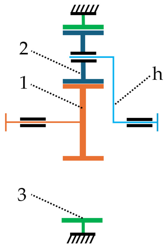
Figure 1.
Basic schematic view of a planetary gear train (1—sun gear; 2—planet; 3—ring gear; h—carrier).
Its primary advantage over other PGT configurations is its high efficiency, which remains nearly constant across the entire range of internal gear ratios p:
Here, is the number of ring gear teeth and is the number of sun gear teeth.
In addition, this type features compact overall dimensions and low mass, while its simplified manufacturing process results in relatively low production costs.
Because of these properties, this PGT type is suitable for both mobile and stationary machinery, regardless of power or velocity requirements. Typical applications include essential systems in helicopters, caterpillar vehicles, mining and agricultural machines, and various other industrial applications.
A comprehensive model of the basic PGT configuration has been presented in the study; for completeness, it will be outlined in this part. The model is defined through objective functions, variables, and system requirements expressed as functional boundaries. The input parameters are as follows: required transmission ratio, input speed, input torque value, service life (in operating hours), application factor, gear materials, the minimum values of the safety factor of the tooth flanks and the safety factor of the tooth root and accuracy grade (according to DIN ISO 1328-1:2018 [44]).
2.1. Objective Functions
The objective functions defined for the planetary gear train (PGT) are established based on the following performance characteristics: overall volume, mass, transmission efficiency, and the production cost of the gear pairs.
2.1.1. Volume
To characterize the overall dimensions, volume V (in ) of the gear pairs is approximated by a cylindrical geometry, where the diameter is represented by the pitch diameter and the height by the face width. Since the planet gears are accommodated within the ring gear, the total gear volume can be expressed as follows:
here, represents the transverse pressure angle (in ), corresponds to the working transverse pressure angle between gears 2 and 3, while denotes the helix angle (in ) measured at the pitch diameter. The symbol represents the number of teeth of the ring gear, while (in ) denotes gear normal module and symbol represents face width of the gears.
2.1.2. Mass
The mass m (in ) of the gear train is calculated as the sum of the individual gear masses. Since the mass of each gear is obtained by multiplying its volume by the material density, this criterion can be expressed as shown in Equation (3):
where k represents the deviation factor of the real gear from a cylindrical shape. The symbols and represent the number of teeth of the sun gear and planet gears, while denotes the number of planet gears.
2.1.3. Efficiency
Efficiency constitutes a critical criterion in both the design and assessment of gear train performance. In planetary transmissions, power losses primarily originate from gear meshing, bearing friction, and lubricant viscosity [45]. Within the scope of this analysis, the efficiency evaluation is restricted to frictional losses occurring at the gear tooth surfaces and contact power losses. Under this assumption, the transmission efficiency is expressed by the following equation:
Here, represents the efficiency when the carrier is stationary.
and is the basic transmission ratio
The efficiency is obtained starting from [36,45]:
where is the power loss coefficient of a gear pair with numbers of teeth and :
Here, is the friction coefficient between the teeth, and is the contact ratio factor. The positive sign applies to external gear pairs, while the negative sign applies to internal gear pairs. Based on the data for μ and f for the selected material values, for this model the following can be adopted: π·μ·f = 0.15 for the external gear pair and π·μ·f = 0.20 for the internal gear pair [36].
Based on the and kinematic equation of the system, Willis method, and power balance, an expression for efficiency (4) is derived.
2.1.4. Production Cost
Economic factors are an essential part of techno-economical optimization. These factors mainly involve production costs, encompassing both the cost of materials and the manufacturing process.
Costs are generally defined as the consumption of goods for business operations, expressed in monetary terms. Goods include materials, energy, and business equipment, as well as human labor, information, or the use of capital and the rights of others [46]. In [46], the manufacturing costs of gears were calculated using a computer program, which includes average processing times and accounting rates of German gearbox manufacturers. The cost comparison covers only the gears, excluding shafts, bearings, housings, and assembly. In accordance with this consideration, the program applied in this study also incorporated machining times for gear production.
The time required to produce the gears is used to quantify costs to produce and serves as a key economic parameter.
This function (describing overall production time) is determined as the sum of the individual times required to manufacture the central sun gear (in min), the planet gears (in min), and the ring gear (in min), i.e.,
The production times (in min) are determined based on the methodologies proposed by Fette, Lorenc, and Höfler [47,48,49].
Priority is given to the first and second objective functions, while the third function in this task does not have particular significance, as well as the manufacturing costs. Consequently, the weighting coefficients are assigned the following values: w1 = 0.45, w2 = 0.45, w3 = 0.1, w4 = 0.1.
2.2. Variables
It is essential to identify the variables in the mathematical model, as each objective function depends on multiple parameters.
The mathematical model considers the following parameters: the number of sun gear teeth , the number of planets gear teeth , the number of ring gear teeth , together with the number of planets , gear module (in ), and face width .
The optimization problem involves variables of varying type as follows: gear tooth counts (, , ) are whole numbers (of any sign), the number of planets () is individual, the module () is chosen from standardized discrete values (ISO 54 [50]), and the face width () is treated as a continuous variable. The numbers of teeth and planets are nondimensional quantities, while the module and face width are measured in millimeters.
The face width as a variable is introduced as a ratio of the pinion facewidth b to the pinion reference diameter (in mm).
2.3. Functional Boundaries
Planetary gear trains constitute a distinct subclass of gear mechanisms, characterized by structural and functional features that differentiate them from conventional gear transmissions. Their correct operation necessitates the consideration of several exceptional requirements that do not typically arise in classical gear systems. These requirements primarily refer to mounting constraints, geometric compatibility, and strength [51].
Regarding the mounting requirements, coaxiality (11), adjacency (12) and conjunction (13), conditions must be fulfilled as follows:
The geometrical conditions are primarily concerned with factors, such as undercutting (, where and are limit numbers of teeth), the relationship between the pressure angle, and the working transverse pressure angle tooth thickness at tip circle expressed by the ratios where is its permissible value, space width at root circle , the value of the transverse contact ratio (where ) and , ratio of sliding velocities at the end points of the line of contact of the external gear pair considering the geometric conditions , the ratio of the pinion facewidth to the pinion reference diameter and tooth profile interference on transitional part of the tooth profile with external gearing, on the tip part of the tooth profile with external gearing and on the root part of the ring gear interference of the tooth tips of the meshing gears, radial interference, among others. Compliance with these conditions is established in accordance with the applicable international standards (ISO TC 60 list of standards 090915 [52]).
Explicit constraints concerning the selection of the numbers of teeth (, , ), the determination of the number of planetary gears , and the adoption of standardized module values are systematically incorporated into the calculation procedures. These constraints are essential to guarantee the kinematic compatibility of the gear set, to ensure a uniform distribution of loads among the planetary gears, and to maintain compliance with standardized design parameters, thereby enhancing both the functional reliability and the manufacturability of the transmission system.
Explicit constraints related to the design variables are included in the solution formation process, determined by combinations of the variables. This group of constraints includes the following boundary values for the profile shift coefficients: ; ; [51].
In parallel, the strength requirements encompassing the safety factors for bending resistance as well as the surface durability of each gear are defined and verified in accordance with ISO 6336 (Parts 1 to 3) [53].
These conditions include the following: the minimum value of the tooth flank safety factor and the minimum value of the tooth root safety factor, , .
2.4. Optimization Procedure
The optimization process for PGTs presented in this paper is the systematic comparison of design alternatives under the same operating conditions, followed by the selection of the most advantageous variant. The procedure commences with the generation of all possible solutions corresponding to the specified input parameters. All admissible 6-tuples of design variables (, , , ) that satisfy the imposed functional constraints are enumerated. For each candidate 6-tuple, the objective function values are computed, thereby forming a comprehensive set of feasible solutions. From this solution space, the optimal configuration is identified based on the defined objective functions and constraint conditions, with the final selection determined by the decision variables.
The mathematical formulation of the nonlinear multicriteria optimization problem can be expressed as outlined [54]:
Here, are objective functions and is the vector of decision variables and is the feasible solutions set. For every point , the mapping associates x with a point in the k-dimensional space defined by the objective functions. The corresponding objective set is therefore:
The symbol “max” is used to indicate the concurrent maximization of all objective functions. Since the minimization of a function is equivalent to the maximization of its negative counterpart, −, the formulation expressed in Equation (14) remains valid within this model. Owing to the discrete nature of the feasible set , the problem is classified as a discrete multicriteria optimization problem. The optimization framework involves six decision variables, related to the fundamental design parameters, expressed as x = ,,) = (,,,,,).
In addition, four objective functions are considered: volume , mass , efficiency , and production costs :
The nonlinear multicriteria optimization problem associated with this task can be mathematically formulated as follows:
Determining the optimal attainable values of each objective function is essential, as these values collectively define the ideal point within the objective space. The components of this ideal point are calculated as follows:
As evident from the definition, multicriteria optimization problems are ill posed from a mathematical perspective. The principal criterion for identifying these “equally good” solutions is the concept of Pareto optimality, which is likewise applied within the framework of this model solution. is Pareto optimal if there is no solution such that holds (x) (y) for all i = 1, …, n and for at least one index holds strict inequality, i.e., . The determination of a set of Pareto optimal solutions is the first step in finding the optimal solution. The next step is an optimal solution choice from the Pareto solutions set [54]. There are several multicriteria optimization methods that can be applied for that purpose, and they will be described in this part as follows: weighted coefficient method, Lexicographic method, ε-constraints method, and Distance method. In [54] it is highlighted that, despite originating from different premises and relying on distinct mathematical formulations, the various methods consistently converge toward harmonized results. This convergence not only underscores the robustness and reliability of the approaches but also ensures that the obtained outcomes preserve a clear physical interpretation.
2.4.1. Weighted Coefficients Method
Accordingly, the scalarized problem in this method is defined as:
In this formulation, the weighting coefficients are defined as positive real numbers, while the normalized objective functions are expressed , where represents the corresponding normalizing coefficients. Within this approach, components of the ideal point are adopted as normalizing coefficients, i.e., for . Consequently, all objective function values are normalized in absolute terms to the range which substantially simplifies the selection of the weighting coefficients. Moreover, the set of solutions derived through this approach are guaranteed to be Pareto optimal [54]. The weighted coefficients method is distinguished by its clear physical interpretation and its proven effectiveness in the optimization of technical systems. A simplified representation of the optimization procedure, incorporating the weighted coefficients method as included in the PLANGEARS software version 3.0, is presented in Figure 2.
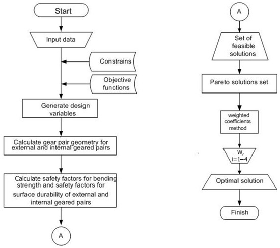
Figure 2.
Simplified optimization procedure algorithm.
Using this model, the optimal solution is derived from the Pareto-efficient alternatives through the application of the weighted coefficients method.
2.4.2. Lexicographic Method
Assuming that the objective functions are ordered according to predefined priorities, it follows that is assigned the highest priority, while , are attributed progressively lower levels of priority, with representing the least significant criterion. Under this prioritization scheme, the following sequence of scalarized optimization problems can be formulated and solved for :
In this approach, the objective functions are maximized sequentially, with the feasible set being progressively reduced at each iteration to the subset of solutions identified as optimal in the preceding step. The final solution obtained through this iterative procedure is likewise guaranteed to be Pareto optimal.
2.4.3. ε-Constraints Method
In the ε-constraints method, a single objective function is selected to be maximized, subject not only to the primary constraints of the problem but also to a set of additional conditions. These supplementary conditions take the form , where , are predefined threshold values for all [54]. Consequently, the optimization problem is reformulated into the following scalarized form:
In this case systematic variation of gives a set of optimal Pareto solutions. The method is widely applied, as it enables precise control over the values of all objective functions, a feature of particular importance in practical engineering applications.
2.4.4. Distance Method
The fundamental principle of this method is to minimize the distance between a specified (generally infeasible) reference point and the attainable objective set . On this basis, the optimization task can be reformulated as the following scalarized problem:
In this context, may represent any appropriate metric function. In the present implementation, the Euclidean distance is adopted, whereby the distance is expressed in the following form:
Here, wi denote positive real numbers representing the weighting coefficients. In most cases, the ideal point is adopted as the reference point. Under this condition, it can be demonstrated that the solution obtained through this method is also Pareto optimal [51].
3. Results
3.1. Design Requirements
The purpose of the work is the application of an optimization procedure to the transmission predicted for usage in a road vehicle winch. All-terrain vehicles are intended for off-road traffic and often end up in a trap from which they cannot escape under their own power. The winch, as an additional equipment of the off-road vehicle, is used to pull the vehicle out of the trap with the help of an external force. This winch, like a winch in the general sense, consists of a drive motor, a drum, and a mechanical transmission between them.
The development of a mechanical transmission involves establishing the characteristics of the working and driving machine and providing an insight into what kind of transformation is needed between them. In this case, the driving machine is the electric motor, and the working machine is the winch drum.
To determine the operating conditions of the transmission, data from real working and on-road machines used in off-road vehicles were used [55].
This winch uses a direct current electric motor with a series excitation power of 4.5 kW [55] as a power unit. The total power used during operation is 1.5 kW at 1500 min−1. It is powered by electricity from the vehicle’s battery (accumulator) with a voltage of 12 V. The engine draws a current of 482 A at maximum load [55]. The electric motor is connected by a hexagonal shaft to the planetary gear transmission. The shaft goes from one end where the motor is located through the drum where it has the brake when the motor is not active, then through the entire transmission all the way to the input gear at the other end. The brake is located inside the drum and when the engine is not running it brakes the drum in relation to the input shaft of the transmission. The drum is connected by direct toothing at the output of the transmission, so that when the brake is active, it brakes the output shaft in relation to the input shaft of the transmission. Thus, the transmission takes all the load with the winch loaded. The brake is released when the electric motor is activated, and the load is then transferred to it.
The transmission output speed is obtained based on the expected speed of the rope and the diameter of the drum. From the traction characteristics of this winch, the maximum traction force (mass) is 4310 kg at a pulling speed of 1.89 m/min. Considering the output speed determined in this way and the input speed from the drive motor, the required transmission ratio is obtained: i = 156.
Due to their characteristics, planetary gear trains are suitable for that usage. First, mass and volume are considerable advantages, e.g., when exploring the different possibilities for placing the transmission on the vehicle.
For that reason, PGTs are predicted for usage in those circumstances. Because of its calculated transmission ratio, a three-stage PGT is suitable for application in the road vehicle winch. The transmission is composed of three stages, each representing a basic planetary gear train (as illustrated in Figure 1). These stages are sequentially connected such that the output of the first stage serves as the input to the second, and the output of the second stage becomes the input to the third. Specifically, the carrier of the first stage drives the sun gear of the second stage, while the carrier of the second stage drives the sun gear of the third stage. The transmission is driven by the sun gear of the first stage, while its output is delivered through the carrier of the third stage.
3.2. Program Results
The task in this paper is to obtain optimal solutions for each planetary stage, and thus for the transmission, considering only the gear pairs. For those purposes, the PLANGEARS software version 3.0 is used.
First, it is necessary to distribute the overall transmission ratio into several transmission ratios of every stage. There are many recommendations for the distribution transmission ratio, since every planetary transmission manufacturer has its own transmission ratio distribution because the overall transmission ratio enables many possibilities of distribution. Also, there are many studies in the literature dealing with this subject. One of them is the recommendations for distribution that ensure equality of ring gear diameters at all stages. Taking into consideration working conditions and the purpose of the machine, the authors of this paper opted for the following solution given in [56] for the distribution of transmission ratios in reducers used in the turning system of cranes and similar devices:
This way approximate values of transmission ratios are obtained, which yields a suitable shape of the gearbox housing. This is significant because the transmission is mounted on the vehicle.
3.2.1. The First Stage (I)
The important required input data are as follows: i = 6.03, = 1500 min−1, P = 4.5 kW, Tin = 28.6 Nm, L = 2000 h, = 1.25, IT7 for all gears, the sun and planet gear material is 16MnCr5, while 42CrMo4 is predicted for the ring gear, the range for the number of teeth of the sun gear is 12 ÷ 36, and tolerances for the gear ratio is ±3%.
Out of 446 feasible solutions, 25 are classified as Pareto optimal. When priority of objective functions is given as specified in Section 2.1, the resulting solution is provided in Table 1, while the associated objective function values are listed in Table 2. The real value of the transmission ratio is = 6.00.

Table 1.
First stage optimal solution derived via the weighted coefficients method.
Table 2.
First stage objective functions.
3.2.2. The Second Stage (II)
The output of the first stage serves as the input to the second stage, the following input data are selected for the application of multicriteria optimization in this stage: i = 5.38, = 250 min−1, = 171.882 Nm, L = 2000 h, = 1.25, IT7 for all gears, the sun and planet gear material is 16MnCr5, while 42CrMo4 is predicted for the ring gear, the range for the number of teeth of the sun gear is 12 ÷ 36, and tolerances for the gear ratio is ±3%. Out of 1823 feasible solutions, 67 are classified as Pareto optimal. When the weighted coefficients method is applied as noted in Section 2.1, the resulting solution is presented in Table 3, while its associated objective function values are listed in Table 4.
Table 3.
Second stage optimal solution derived via the weighted coefficients method.
Table 4.
Second stage objective functions.
The real value of the transmission ratio is = 5.25.
3.2.3. The Third Stage (III)
Since the output from the second stage directly drives the third stage, the input dataset for the multicriteria optimization of this stage is determined as follows: i = 4.95, = 47.619 min−1, = 902.38 Nm, L = 2000 h, = 1.25, IT7 for all gears, the sun and planet gear material is 16MnCr5, while 42CrMo4 is predicted for the ring gear, the range for the number of teeth of the sun gear is 12 ÷ 36, and tolerances for the gear ratio is ±3%.The optimization process generated 2203 feasible solutions, among which 67 are Pareto optimal. Through the application of the weighted coefficients method, following the same procedure as in the first and second stages, the resulting solution is given in Table 5, with its objective function values provided in Table 6.
Table 5.
Third stage optimal solution derived via the weighted coefficients method.
Table 6.
Third stage objective functions.
The real value of the transmission ratio is = 4.85.
A summary view of variables is shown in Table 7, and material properties of the gears are shown in Table 8 and Table 9. The parameters satisfy the conditions for gear engagement as found in [57].
Table 7.
Specifications of the planetary gear trains.
Table 8.
Material properties of the sun and planets gear 16MnCr5.
Table 9.
Material properties of the ring gear 42CrMo4.
The driveline of the three-stage planetary gear reducer is given in Figure 3.
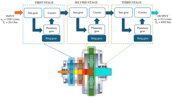
Figure 3.
Driveline of the three-stage planetary gear train.
After the optimization, the total volume of the three-stage planetary gearbox was reduced by 16.2%, the mass by 16.5%, and the production costs by 6.2%, while maintaining an almost unchanged utilization rate. A comparative value of variables and objective functions are shown in Table 10.
Table 10.
Comparison values of variables and objective functions of the three-stage PGT before and after optimization.
3.3. Simulation Model
Mounting conditions and geometrical conditions are included in the mathematical model, but transmission error check and load distribution analysis are not included in the algorithm. Considering the significance of transmission error and load distribution of the planets and the facts that may lead to irregularities, other software is applied in the simulation model.
To assess the functionality and service life of the gearbox, a contact analysis was conducted according to the simulation model formed toward the input parameters obtained by the Pareto method in PLANGEARS software version 3.0. Next, the simulation model was created in the KISSsoft software Release 2025. Specifically, the power transmission errors and power in each stage were analyzed. The simulation results, the maximum and minimum values, and the peak-to-peak transmission errors (PPTE) and power loss were observed and are shown in Table 11. The results show that the PPTE value is the highest in the second stage of the planetary gearbox, while it is the lowest in the first stage. This indicates that noise and vibrations are present most in the second stage of the planetary gearbox, where failure is also possible, while in the first stage of the transmission the probability of failure is the lowest. In the third stage, the PPTE value decreases compared to the second stage. When it comes to power loss, the highest PPTE value is also present in the second stage, while it is lowest in the third stage.
Table 11.
Results of transmission error and PPTE.
The transmission error curves for all three stages are shown in Figure 4. In the third stage, it can be observed that the curve oscillates depending on the rotation angle and transmission error, while in the first and second stage, the oscillation is less pronounced.
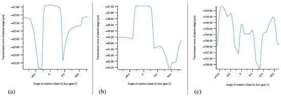
Figure 4.
Transmission error curve of (a) the first stage, (b) the second stage, and (c) the third stage.
The load distribution diagrams of the planets during the rotation of the sun gear for all three stages of the transmission is shown in Figure 5. In the first and second stage the load distribution is approximately equal and all planets transmit approximately equal loads depending on the rotation angle of the sun gear. The calculated value of the distribution factor using the expression for all three planets in the first and second stage is one. In the third stage, the diagram shows a significant uneven distribution of the load on the planets, while the calculated value of for the first planet is 1, the second planet 1.159, and the third planet 1.232.
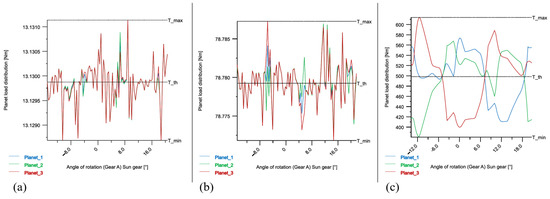
Figure 5.
Planet load distribution of (a) the first stage, (b) the second stage, and (c) the third stage.
The uneven distribution of the load between the sun gear and planet gear can lead to increased Hertzian pressure on the flanks of the teeth, which later in the service life can manifest itself in the appearance of fatigue damage in the form of cracks (pitting fatigue). With that, it is necessary to show and analyze the behavior of the hertzian pressure curve in relation to the angle of rotation of the sun gear. As shown in Figure 6, the maximum Hertz pressure value is the highest in the third stage, and it is . According to the characteristics of the material 16MnCr5 based on the ISO 6336 standard [53], the permissible Hertz pressure is . Although it is close to the limit, it can be concluded that the Hertz pressure value in the third gear is within the permissible limits.
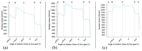
Figure 6.
Hertzian pressure on the sun gear of (a) the first planet stage, (b) the second planet stage, and (c) the third planet stage.
4. Conclusions
This study presented development and optimization of a three-stage planetary gear transmission for winch systems used in on-road and off-road vehicles. The main objectives were to minimize overall dimensions and mass, increase torque capacity, and reduce production costs while ensuring reliability and durability.
Through a multicriteria optimization approach combining the Pareto method and weighted coefficients, the proposed design achieved notable improvements compared to the initial configuration. The optimization resulted in a 16.5% reduction in total mass, and the total volume of the three-stage planetary gearbox was reduced by 16.2%, and also a 6.2% decrease in production costs, all within the allowable stress and safety limits defined by ISO 6336-5.
Simulation and contact analysis using KISSsoft confirmed the effectiveness of the optimized design. The second stage was identified as the most critical in terms of transmission error and power loss, while the third stage showed the highest Hertzian pressure but remained within acceptable limits. Overall, the optimized transmission meets all functional and structural requirements, offering a compact, efficient, and cost-effective solution for winch applications.
Future work should focus on refining tooth profile modifications (profile shifting and tip relief) and improving planet gear mounting to reduce transmission error and enhance load distribution, particularly in the second and third stages.
Author Contributions
Conceptualization, J.S.-M., A.M. and D.M.; methodology Ž.Ć., J.S.-M., D.M. and M.P.; formal analysis, writing—original draft preparation, M.P.; writing—review and editing, J.S.-M., M.P., A.M., D.M. and Ž.Ć.; visualization, J.S.-M., A.M. and M.P.; resources, D.M. and Ž.Ć.; supervision, D.M. All authors have read and agreed to the published version of the manuscript.
Funding
This research was financially supported by the Ministry of Science, Technological Development and Innovation of the Republic of Serbia (Contract No. 415-03-137/2025-03/200109).
Informed Consent Statement
Not applicable.
Data Availability Statement
The data supporting reported results are not stored in any publicly archived datasets. The readers can contact the corresponding author for any further clarification of the results obtained.
Conflicts of Interest
The authors declare no conflicts of interest.
Nomenclature
| number of sun gear teeth | ||
| number of planet gear teeth | ||
| number of ring gear teeth | ||
| number of planet gears | ||
| normal module | (mm) | |
| facewidth | (mm) | |
| reference diameter | (mm) | |
| transmission ratio | ||
| basic transmission ratio | ||
| real transmission ratio | ||
| application factor | ||
| input rotational speed | ( | |
| P | power | (kW) |
| input torque | (Nm) | |
| service life | (h) | |
| transverse pressure angle | (°) | |
| working transverse pressure angle | (°) | |
| helix angle at reference circle | (°) | |
| volume of gear pairs | (mm3) | |
| mesh load factor | ||
| m | mass of gear train | (kg) |
| efficiency | ||
| efficiency when the carrier is stationary | ||
| deviation factor of real gear from cylindrical shape | ||
| production time for sun gear | (min) | |
| production time for planet gears | (min) | |
| production time for ring gear | (min) | |
| fatigue strength for Hertzian pressure | (N/mm2) |
Abbreviations
| PGT | Planetary Gear Trains |
| PPTE | Peak-to-Peak Transmission Error |
References
- Xue, Q.; Zhang, X.; Geng, C.; Teng, T. Gear shift coordinated control strategy based on motor rotary velocity regulation for a novel hybrid electric vehicle. Appl. Sci. 2021, 11, 12118. [Google Scholar] [CrossRef]
- Wang, A.; Li, Y.; Du, X.; Zhong, C. Diesel engine gearbox fault diagnosis based on multi-features extracted from vibration signals. IFAC-PapersOnLine 2021, 54, 33–38. [Google Scholar] [CrossRef]
- Vrcan, Z.; Stefanović-Marinović, J.; Tica, M.; Troha, S. Research into the properties of selected single speed two-carrier planetary gear trains. J. Appl. Comput. Mech. 2022, 8, 699–709. [Google Scholar]
- Kundu, P.; Darpe, A.K.; Kulkarni, M.S. A review on diagnostic and prognostic approaches for gears. Struct. Health Monit. 2020, 20, 2853–2893. [Google Scholar] [CrossRef]
- Tica, M.; Vrcan, Ž.; Troha, S.; Marinković, D. Reversible planetary gearsets controlled by two brakes, for internal combustion railway vehicle transmission applications. Acta Polytech. Hung. 2023, 20, 95–108. [Google Scholar] [CrossRef]
- Mao, K.; Greenwood, D.; Ramakrishnan, R.; Goodship, V.; Shrouti, C.; Chetwynd, D.; Langlois, P. The wear resistance improvement of fibre reinforced polymer composite gears. Wear 2019, 426–427, 1033–1039. [Google Scholar] [CrossRef]
- Zhang, L.; Qiu, S. Dynamic correction analysis and optimization model of gear pair based on the normalization of gear modification parameters. Tech. Vjesn. 2024, 31, 2045–2054. [Google Scholar]
- Lee, J.; Yun, S. Development of the fatigue life model for plastic gears of automotive actuators under vibration. Eng. Fail. Anal. 2023, 144, 106992. [Google Scholar] [CrossRef]
- Čular, I.; Vučković, K.; Glodež, S.; Tonković, Z. Computational model for bending fatigue prediction of surface hardened spur gears based on the multilayer method. Int. J. Fatigue 2022, 161, 106892. [Google Scholar] [CrossRef]
- Miltenović, A.; Banić, M.; Tanasković, J.; Stefanović-Marinović, J.; Rangelov, D.; Perić, M. Wear load capacity of crossed helical gears. Facta Univ.-Ser. Mech. Eng. 2024, 22, 125–138. [Google Scholar] [CrossRef]
- Zhao, H.; Chen, J.; Xu, G. Design methodology and characteristics analysis of high-order multi-segment deformed eccentric non-circular gear. Facta Univ.-Ser. Mech. Eng. 2024, 22, 217–234. [Google Scholar] [CrossRef]
- Nutakor, C.; Kłodowski, A.; Sopanen, J.; Mikkola, A.; Pedrero, J.I. Planetary gear sets power loss modeling: Application to wind turbines. Tribol. Int. 2017, 105, 42–54. [Google Scholar] [CrossRef]
- Mao, Y.; Niu, S.; Yang, Y. Differential evolution based multi-objective optimization of the electrical continuously variable transmission system. IEEE Trans. Ind. Electron. 2017, 65, 2080–2089. [Google Scholar] [CrossRef]
- Xu, H.; Kahraman, A.; Anderson, N.E.; Maddock, D.G. Prediction of mechanical efficiency of parallel-axis gear pairs. J. Mech. Des. 2007, 129, 58–68. [Google Scholar] [CrossRef]
- Vrcan, Ž.; Troha, S.; Marković, K.; Marinković, D. Analysis of complex planetary gearboxes. Spectr. Mech. Eng. Oper. Res. 2024, 1, 227–249. [Google Scholar] [CrossRef]
- Xu, X.; Chen, J.; Lin, Z.; Qiao, Y.; Chen, X.; Zhang, Y.; Xu, Y.; Li, Y. Optimization design for the planetary gear train of an electric vehicle under uncertainties. Actuators 2022, 11, 49. [Google Scholar] [CrossRef]
- Kalmaganbetov, S.A.; Isametova, M.; Troha, S.; Vrcan, Ž.; Marković, K.; Marinković, D. Selection of optimal planetary transmission for light electric vehicle main gearbox. J. Appl. Comput. Mech. 2024, 10, 742–753. [Google Scholar]
- Wang, R.; Chen, Y.; Feng, D.; Huang, X.; Wang, J. Development and performance characterization of an electric ground vehicle with independently actuated in-wheel motors. J. Power Sources 2011, 196, 3962–3971. [Google Scholar] [CrossRef]
- Hang, P.; Chen, X. Towards Autonomous Driving: Review and perspectives on configuration and control of four-wheel independent drive/steering electric vehicles. Actuators 2021, 10, 184. [Google Scholar] [CrossRef]
- Zheng, H.; Deng, W.; Song, W.; Cheng, W.; Cattani, P.; Villecco, F. Remaining useful life prediction of a planetary gearbox based on meta representation learning and adaptive fractional generalized pareto motion. Fractal Fract. 2024, 8, 14. [Google Scholar] [CrossRef]
- Vrcan, Ž.; Troha, S.; Marković, K.; Marinković, D. Parametric selection of optimized epicyclic gearbox layouts for wind power plant applications. Appl. Sci. 2024, 14, 9423. [Google Scholar] [CrossRef]
- Xu, X.; Chen, X.; Liu, Z.; Yang, J.; Xu, Y.; Zhang, Y.; Gao, Y. Multi-objective reliability-based design optimization for the reducer housing of electric vehicles. Eng. Optim. 2022, 54, 1324–1340. [Google Scholar] [CrossRef]
- Parmar, A.; Ramkumar, P.; Shankar, K. Macro geometry multi-objective optimization of planetary gearbox considering scuffing constraint. Mech. Mach. Theory 2020, 154, 104045. [Google Scholar] [CrossRef]
- Miler, D.; Žeželj, D.; Lončar, A.; Vučković, K. Multi-objective spur gear pair optimization focused on volume and efficiency. Mech. Mach. Theory 2018, 125, 185–195. [Google Scholar] [CrossRef]
- Miler, D.; Lončar, A.; Žeželj, D.; Domitran, Z. Influence of profile shift on the spur gear pair optimization. Mech. Mach. Theory 2017, 117, 189–197. [Google Scholar] [CrossRef]
- Abderazek, H.; Ferhat, D.; Atanasovska, I. Adaptive mixed differential evolution algorithm for bi-objective tooth profile spur gear optimization. Int. J. Adv. Manuf. Technol. 2017, 90, 2063–2073. [Google Scholar] [CrossRef]
- Abderazek, H.; Sait, S.; Yildiz, A.R. Optimal design of planetary gear train for automotive transmissions using advanced meta-heuristics. Int. J. Veh. Des. 2019, 80, 121–136. [Google Scholar] [CrossRef]
- Maputi, E.S.; Arora, R. Multi-objective optimization of a 2-stage spur gearbox using NSGA-II and decision-making methods. J. Braz. Soc. Mech. Sci. Eng. 2020, 42, 477. [Google Scholar] [CrossRef]
- Wang, C. Multi-objective optimal design of modification for helical gear. Mech. Syst. Signal Process. 2021, 157, 107762. [Google Scholar] [CrossRef]
- Artoni, A. A methodology for simulation-based, multiobjective gear design optimization. Mech. Mach. Theory 2019, 133, 95–111. [Google Scholar] [CrossRef]
- Patil, M.; Ramkumar, P.; Shankar, K. Multi-objective optimization of the two-stage helical gearbox with tribological constraints. Mech. Mach. Theory 2019, 138, 38–57. [Google Scholar] [CrossRef]
- Arnaudow, K.; Karaivanov, D. Einfache bestimmung-systematik, eigenschaften und möglichkeiten von zusammengesetzten mehrsteg-planetengetrieben. Antriebstechnik 2005, 5, 58–65. [Google Scholar]
- Yaw, M.W.; Chong, K.H. Optimize volume for planetary gear train by using algorithm based artificial immune system. Int. J. Adv. Trends Comput. Sci. Eng. 2020, 9, 3757–3762. [Google Scholar] [CrossRef]
- Sedak, M.; Rosić, B. Multi-objective optimization of planetary gearbox with adaptive hybrid particle swarm differential evolution algorithm. Appl. Sci. 2021, 11, 1107. [Google Scholar] [CrossRef]
- Sedak, M.; Rosić, M. Hybrid butterfly optimization and particle swarm optimization algorithm-based constrained multi objective nonlinear planetary gearbox optimization. Appl. Sci. 2023, 13, 11682. [Google Scholar] [CrossRef]
- Daoudi, K.; Boudi, E.M.; Abdellah, M. Genetic approach for multiobjective optimization of epicyclical gear train. Math. Probl. Eng. 2019, 19, 9324903. [Google Scholar] [CrossRef]
- Čabala, J.; Jadlovsky, J. Choosing the optimal production strategy by multi-objective optimization methods. Acta Polytech. Hung. 2020, 17, 7–26. [Google Scholar] [CrossRef]
- Lee, N.G.; Lee, D.H.; Jung, Y.J.; Siddique, M.A.A.; Nam, K.C.; Kim, T.B.; Choi, C.H.; Kim, Y.J. Analysis of transmission error for compound planetary gear reducer by tooth profile modification. In Proceedings of the 2019 ASABE Annual International Meeting, Boston, MA, USA, 7 July 2019; p. 1901030. [Google Scholar]
- Fiausch, A. Effect analysis of machining errors of the axle wheel hub planet carrier on function and durability-related parameters. Eng. Proc. 2024, 79, 46. [Google Scholar]
- Parab, R.; Salve, V.; Ghadi, P. Gearbox noise reduction using engineering plastics gears. Int. J. Eng. Res. Technol. (IJERT) 2019, 7, 23–26. [Google Scholar]
- Lin, W.; Chang, D.; Li, H.; Chen, J.; Huang, F. Dynamic characteristics analysis and optimization design of two-stage helix planetary reducer for robots. Machines 2025, 13, 245. [Google Scholar] [CrossRef]
- Hu, Y.; Rualy, L.; Talbot, D.; Kahraman, A. A theoretical study of the overall transmission error in planetary gear sets. J. Mech. Eng. Sci. 2019, 233, 1–12. [Google Scholar] [CrossRef]
- Narayankutty, A. A review of design and analysis of a 3-stage planetary gearbox. Int. J. Adv. Res. Innov. Ideas Educ. 2016, 2, 395–399. [Google Scholar]
- DIN ISO 1328-1:2018; Cylindrical Gears—ISO System of Accuracy—Part 1: Definitions and Allowable Values of Deviations. Deutsches Institut für Normung e.V.: Berlin, Germany, 2018.
- Del Castilo, J.M. The analytical expression of the efficiency of planetary gear trains. Mech. Mach. Theory 2002, 37, 197–214. [Google Scholar] [CrossRef]
- Ehrlenspiel, K.; Kiewert, A.; Lindemann, U.; Mörtl, M. Kostenmanagement bei der Integrierten Produktentwicklung, 8th ed.; Springer: Berlin/Heidelberg, Germany, 2020. [Google Scholar]
- FETTE-Technologie. Ihr Profit. In Die Schnittbedingungen beim Wälzfräsen; Wilhelm Fette, GMBH: Schwarzenbek, Germany, 2004. [Google Scholar]
- Verzahnwerkzeuge, Ein Handbuch für Konstruktion und Betrieb, 3rd ed.; Verzahntechnik LORENZ GmbH&Co: Ettlingen, Germany, 1961.
- BHS HÖFLER. Operating Instructions for Gear Grinding Machines. Models 630-1000/2./125÷630-1000/2./166, 630-1000/4./01÷630-1000/2./67 [Manual]. BHS HÖFLER GmbH (internal document). Unpublished work.
- ISO 54; Cylindrical Gears for General Engineering and for Heavy Engineering—Modules. International Organization for Standard-ization: Geneva, Switzerland, 1996.
- Kudriavtsev, V.N.; Kirdyiashev, I.N. Planetary Gears Handbook; Mashinostroenie: St. Petersburg, Russia, 1977; pp. 73–78. [Google Scholar]
- Available online: https://www.jgma.org/wp-content/themes/haguruma/pdf/Standard_ISO.pdf (accessed on 19 October 2025).
- ISO 6336; Calculation of Load Capacity of Spur and Helical Gears. International Organization for Standardization: Geneva, Switzerland, 2019.
- Miettinen, K. Nonlinear Multiobjective Optimization; Kluwer Academic Publishers: Boston, MA, USA, 1999. [Google Scholar]
- Available online: https://international.warn.com/95xp-winch-68500 (accessed on 20 May 2025).
- Orlić, Ž.; Orlić, G. Planetary Transmissions; Faculty of Engineering, University of Rijeka: Rijeka, Croatia, 2006. (In Croatian) [Google Scholar]
- Roth, K. Zahnradtechnik. Band I: Stirnradverzahnungen—Geometrische Grundlagen, 1st ed.; Springer: Berlin/Heidelberg, Germany, 1989. [Google Scholar]


Disclaimer/Publisher’s Note: The statements, opinions and data contained in all publications are solely those of the individual author(s) and contributor(s) and not of MDPI and/or the editor(s). MDPI and/or the editor(s) disclaim responsibility for any injury to people or property resulting from any ideas, methods, instructions or products referred to in the content. |
© 2025 by the authors. Licensee MDPI, Basel, Switzerland. This article is an open access article distributed under the terms and conditions of the Creative Commons Attribution (CC BY) license (https://creativecommons.org/licenses/by/4.0/).