Abstract
This research tackles the intricate machining properties of cylindrical aspheric surfaces with a versatile adaption approach utilizing a robotic arm and a compact tool head, incorporating trajectory optimization. A three-step integrated error compensation framework was established as the core to address spatial inaccuracies in robotic systems, incorporating coordinate measuring machine (CMM)-based cylindrical generatrix offset correction, laser tracker-assisted progressive coordinate calibration, and contour profiler-driven feedback compensation. Complemented by a curvature-driven trajectory design, the method ensures uniform polishing coverage for non-uniform curvature surfaces. Experimental validation on S-TiH53 glass cylindrical aspheric components demonstrated a surface profile accuracy of peak-to-valley (PV) value ≤ 2 μm, meeting stringent requirements for high-power laser applications. This systematic approach enhances both efficiency and accuracy in robotic polishing, offering a viable solution for high-end optical manufacturing.
1. Introduction
Ultra-precision machining has emerged as an essential manufacturing paradigm for high-value sectors such as microelectronics, advanced optics, and aerospace. In these fields, the increasing demand for superior product performance necessitates techniques capable of achieving sub-micrometer accuracy [1,2]. Within this context, cylindrical aspherical optical components—characterized by intricate geometries that combine aspheric curvatures with prismatic features—play critical roles in laser beam deflection, optical path control in communication systems, and beam shaping for high-power lasers. However, their fabrication, particularly during the final polishing stage, faces persistent challenges in achieving the required form accuracy crucial for functional efficacy.
Robotic arms have emerged as a transformative solution for complex optics polishing, leveraging their exceptional dexterity, expansive workspace, and capacity for force-controlled operations to overcome traditional machining bottlenecks [3]. However, most commercially available polishing robots exhibit a maximum repeat positioning accuracy of only 0.02 mm, attributable to inherent precision limitations. The robotic arm’s polishing of intricate curved surfaces is deficient in comprehensive high-precision control methodologies. High-precision controlled polishing poses considerable challenges and generally requires iterative cycles of measurement, compensation, and adjustment [4].
To address the existing technological gap, this study introduces an innovative methodology centered on a hierarchical three-phase integrated error compensation strategy for cylindrical aspherical components, complemented by curvature-driven trajectory design. The research aims to develop an adaptive equidistant trajectory algorithm that dynamically modulates polishing paths based on local curvature variations, thereby minimizing peak-to-valley (PV) non-uniformity through analytical modeling of material removal profiles. Simultaneously, we devise a cascaded error compensation protocol addressing spatial inaccuracies at progressively finer scales, commencing with coordinate measuring machine (CMM)-based correction of cylindrical generatrix offsets, advancing to laser tracker-assisted calibration of robotic coordinate systems for angular and positional refinement, and culminating in profilometer-guided dwell-time [5,6] modulation for residual contour elimination.
This work delivers substantive advances across theoretical and practical domains: Centered on the multi-stage integrated error compensation framework, and complemented by curvature-driven trajectory design, the method achieves experimentally verified PV ≤ 2 μm surface accuracy within a 15 mm evaluation width—surpassing inherent robotic precision limits and satisfying stringent thresholds for high-power laser optics. The cascaded compensation architecture establishes a transformative paradigm for robotic ultra-precision manufacturing, effectively closing the control loop in traditionally open-loop polishing processes. From an application perspective, the framework enables efficient production of cylindrical aspherics essential to next-generation laser processing equipment, optical communications payloads, and precision instruments such as spectrometers and interferometers.
The remainder of this paper is structured as follows. Section 2 reviews the existing literature. Section 3 presents the curvature-driven trajectory design. Section 4 details the integrated error compensation methodology. Section 5 describes the experimental setup and results. Section 6 provides a discussion, and Section 7 concludes the paper.
2. Related Research
Traditional polishing methods, including manual polishing [7,8] and advanced processes like magnetorheological finishing (MRF) [9] and ion beam polishing (IBP) [10], exhibit inherent limitations. These limitations become apparent when such methods are applied to freeform surfaces. Issues related to trajectory planning constraints, spatial interference in multi-axis systems, and insufficient control over dynamic contact forces often result in prolonged process cycles, compromised surface integrity, and prohibitive costs associated with high-precision applications.
Traditional research has focused mainly on optimizing motion trajectories, while the calculation and compensation of robotic arm posture and spatial errors have received inadequate attention. Methodologically, the supporting curvature-driven trajectory design initiates with S-shaped grating path modeling [11,12], where two-dimensional removal profiles are derived to quantify the influence of pitch distance and feed rate on depth uniformity. For surfaces exhibiting non-uniform curvatures, adaptive line-spacing calculations incorporate asymmetric profile superposition effects, enabling PV minimization through localized adjustments in path density. Current research predominantly emphasizes trajectory planning but overlooks the post-polishing surface accuracy, resulting in an incomplete closed-loop control framework [13,14].
Complementing this trajectory framework, the three-tiered compensation system systematically targets spatial errors [15]: Initial CMM metrology rectifies generatrix offsets induced by multi-stage machining and fixturing misalignments through segmented peak-point calibration; subsequent laser tracker deployment resolves robotic coordinate system errors by iteratively quantifying angular deviations (α, β, γ) via dial gauges and positional offsets through target-ball tracking; finally, a closed-loop profilometric feedback mechanism employs Fourier-based dwell-time calculations—informed by residual error deconvolution—to eliminate contour irregularities, with CMM-referenced peak points ensuring metrological consistency.
3. Curvature-Driven Trajectory Design for Robotic Arm Polishing
3.1. Grating Trajectory Removal Profile Modeling
Grating trajectories, widely adopted in industrial applications, exhibit a grid pattern that uniformly covers workpiece surfaces. For cylindrical aspheric components, an S-shaped grating trajectory is identified as optimal. By maintaining constant trajectory curvature and tool geometry, the material removal profile is characterized in both the trajectory direction and its perpendicular orientation. Neglecting edge effects, the 2D material removal profile effectively represents the 3D grating trajectory’s removal behavior. This section calculates the 2D profile to evaluate the influence of grating spacing and process parameters on removal depth and uniformity. Furthermore, we optimize these parameters to enhance uniformity across the internal region.
The removal profile of the grating polishing trajectory is modeled as shown in Figure 1. The trajectory consists of linear segments and exhibits uniformity in two directions, enabling planar analysis of the removal profile. A coordinate system O-XYZ is defined at the workpiece center O, with the grating trajectory in the XOY plane and the profile cross-section in the XOZ plane. The two-dimensional material removal contour is formulated as follows:
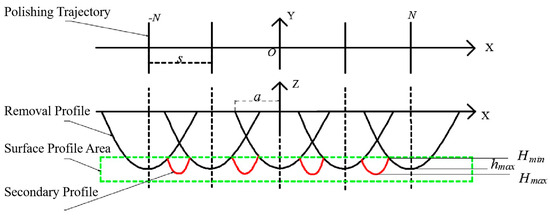
Figure 1.
Schematic diagram of grating trajectory 2D removal profile.
In Equation (1), hi represents the i-th removal profile in the XOY coordinate system, where i ∈ (−N, N); H is the superimposed removal profile, which is a function of coordinate position X, grating pitch s, and feed speed v.
Equation (1) helps analyze how grating pitch and process parameters affect material removal depth and surface uniformity. With constant machining parameters, the superimposed removal profile’s period is the pitch s, and the contact radius is a. If s = 2a/N (where N is a positive integer), only N profiles overlap within one period s, as in Figure 2a. If 2a/N < s < 2a/(N − 1), both N and N − 1 profiles overlap within one period s, as in Figure 2b.
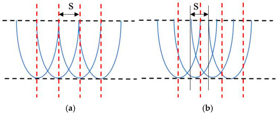
Figure 2.
Schematic diagram of superimposed removal profiles with different spacings. (a) s = 2a/N; (b) 2a/N < s < 2a/(N − 1).
When m removal profiles are superimposed within one spacing period s, the removal depth is obtained as shown in Equation (2).
Equation (3) allows categorizing the discussion of maximum and minimum removal profile values. The graph shows two situations for maximum removal depth:
- (a)
- When m = 2k + 1, hm achieves its maximum at X = ks, as show in Equation (3).
- (b)
- When m = 2k, hm achieves its maximum at X = (k − 1) s + s/2, as shown in Equation (4).
As shown in Figure 2, if 2a/N < s < 2a/(n − 1), there are two minimal values, and the smallest should be taken. For the N-th spacing interval, with m = N and m = N − 1, hm reaches its minimum value at X = (N−1) s − a, as shown in Equation (5).
The assessment of surface quality in polishing can be conducted through the evaluation of peak-to-valley (PV) value. Tam et al. [16] modeled the removal profile as a symmetric parabola to determine the optimal trajectory. Their research indicates that the impact of profile superposition varies with position due to trajectory planning, necessitating specific analyses for each individual case.
3.2. Curvature-Driven Variable-Spacing Trajectory Design for Complex Curvature Surfaces
The method for calculating optimal line-spacing by classifying the superposition of removal profiles is applicable to flat surfaces. However, conventional trajectories and line-spacing plans always fail to ensure uniform material removal. This challenge arises from the mathematical properties of the components and the spatial superposition of removal trajectories. These issues have been investigated by researchers in the field.
We propose evaluating material removal uniformity through profile-based analysis of grating spacing effects. For rotationally symmetric aspheric surfaces, their diametral generatrix inherently encapsulates the full-surface characteristics, enabling efficient localized profile assessment. The S-shaped grating trajectory is designed to exploit the translational symmetry of cylindrical aspheric surfaces along the cylindrical axis (Y-axis). This symmetry ensures that the material removal profile (modeled in Section 3.1) is consistent across the Y-axis, allowing trajectory spacing adjusted for the generatrix (X-Z plane) to be extended directly along the Y-axis—simplifying trajectory generation while maintaining uniform coverage. For double-curvature surfaces without translational symmetry (e.g., toroidal surfaces), this trajectory can be adapted to a curvature-adaptive grid by extracting sampling generatrices in both curvature directions, with the removal profile overlap model remaining applicable.
If there are n removal profiles along the aspheric generatrix. Let the distance between the aspheric origin O and point p1 be s1, and the distance between adjacent trajectory points pi−1 and pi be si. Assuming adjacent removal profiles lie in the same plane, the profiles h1, h2, …, hi, …, hn can be sequentially arranged along the X-axis according to the distances s1, s2, …, si, …, sn. This allows for mathematical calculations and a simplified drawing of the 2D material removal contour of the aspheric meridian section, as shown in Figure 3a. If an equidistant polishing trajectory in x is used along the generatrix, si will increase with the curvature.
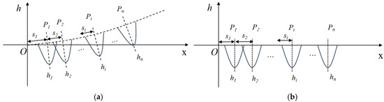
Figure 3.
Schematic diagram of 2D removal profile of aspheric generatrix. (a) Schematic diagram before simplification. (b) Schematic diagram after simplification.
The superimposed 2D material removal profile can be expressed as Equation (6).
For aspheric surfaces, polishing trajectory spacing varies. This section adjusts trajectory spacing by superimposing adjacent removal profiles to generate a curvature-matched trajectory. As shown in Figure 3b, for adjacent trajectories P1 and P2 on the same generatrix with profiles hi(xi) and hi+1(xi+1), the overall peak-to-valley value is given by Equation (7).
Due to the curvature of the aspheric surface, the material removal profile exhibits a degree of asymmetry. Nevertheless, for aspheric surfaces characterized by large radii of curvature and for most complex-shaped optical components, this deviation is considered negligible.
4. Error Compensation Research in Robotic Arm Polishing Processes
Due to the inherent precision limitations of robotic arms and the stringent accuracy requirements associated with optical components, implementing error compensation in robotic arm polishing is essential. This study outlines a three-step methodology for high-precision spatial error compensation designed for robotic arms, using cylindrical aspheric surfaces as a case example. The proposed method is relevant to intricate optical components, as demonstrated in Figure 4.
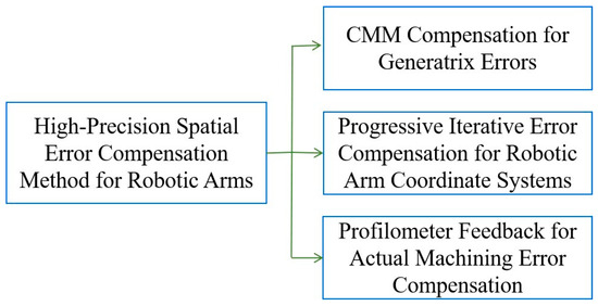
Figure 4.
Three-step method for spatial error compensation of robotic arm.
4.1. Cylindrical Generatrix Offset Compensation Based on CMM
This section discusses the first step of the three-step method: compensating for generatrix offset using CMM. The CMM is utilized to evaluate generatrix errors. For optical components with excessive cylindrical length, multi-step cutting techniques are required, which may introduce cylindrical direction errors. Additionally, deviations in the profilometer’s measurement reference may occur during compensation polishing. The CMM, equipped with micrometer-level precision, enables precise measurement and calibration of these errors.
By utilizing the CMM, deviations among generatrices within the defined cylindrical area are quantified and compensated through point cloud coordinate correction. This method optimizes the accuracy of point cloud computation for generatrix profiles and enhances the uniformity of deviation correction across the workpiece, as demonstrated in Figure 5a,b. The procedure is detailed as follows:
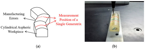
Figure 5.
Schematic diagram of generatrix offset compensation. (a) Cylindrical Manufacturing Errors. (b) CMM-based measurement of cylindrical generatrix for error compensation calibration.
The measurement object is segmented into regions based on a specified interval dseg (one-third of the total workpiece length). The CMM evaluates the generatrix profile across these segments at intervals of dseg. The peak point within each segment serves as a reference to calculate the offset of peak points along the generatrix direction between adjacent regions. These results are integrated into the point cloud computation, enabling an overall offset calculation at each segment position.
Furthermore, the CMM measurement data of the aspheric generatrix is utilized to correct the reference deviation inherent in the profilometer. While the profilometer employs the generatrix peak as its reference, the CMM-derived peak points standardize this reference for feedback compensation during polishing.
The CMM measurement focuses on generatrix offset because the 2D generatrices of cylindrical aspherics fully represent the 3D surface geometry. This 2D representability reduces measurement complexity—only 3–5 generatrices need to be measured to achieve full-surface compensation. For other double-curvature surfaces, the CMM measurement can be adjusted to target key curvature feature points, with the compensation goal (correcting initial manufacturing deviations) unchanged.
4.2. High-Precision Robotic Arm Coordinate System Progressive Error Compensation
This section represents the second step in the three-step compensation method. Robotic arms typically operate within three coordinate systems: the world coordinate system, the tool coordinate system, and the workpiece coordinate system, as shown in Figure 6. The flange coordinate system, which is defined relative to the end-effector (flange), specifies its position and orientation concerning the tool head. The base of the polishing tool head is fixed, it follows that in this section, the flange coordinate system aligns with the tool coordinate system.
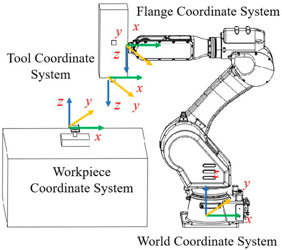
Figure 6.
Schematic diagram of coordinate systems of each component in the robotic arm polishing platform.
The proposed method integrates the characteristics of robotic arm control with the principles of establishing a workpiece coordinate system. This progressive error compensation approach transitions from a coarse to a fine coordinate system in three distinct steps:
- (a)
- First, the end-effector of the robotic arm approximately establishes the workpiece coordinate system. This initial step incurs an error ranging from 20 to 30 μm due to limited positioning accuracy, which encompasses deviations in three spatial directions and positions.
- (b)
- Second, a dial gauge is employed to accurately measure deviations in three dimensions, thereby maintaining error control at the micrometer level.
- (c)
- Finally, a laser tracker is employed to calibrate the relative position between the end-effector of the robotic arm and the workpiece, thereby obtaining deviations at three distinct positions. Subsequently, it plans for point cloud calibration to refine both the directional and positional errors within the spatial coordinate system. Following three progressive iterations, a high-precision workpiece coordinate system is established.
The specific steps for the end-effector of the robotic arm to establish a workpiece coordinate system are outlined as follows: Utilizing the three-point method, the center of the spherical polishing head is replaced with a tool tip to record three endpoints on the cylindrical aspheric surface, thereby constructing the coordinate system.
The detailed procedure for measuring directional deviations using a dial gauge is described below: A dial gauge is attached to the end-effector via a magnetic base, measuring the X, Y, and Z directions relative to the robotic arm and fixture table. The movement distances along with dial gauge readings are employed to calculate angular deviations across all three axes.
Additionally, a laser tracker measures the relative position between the tool tip of the robotic arm and the workpiece, yielding three positional offsets. Taking a cylindrical aspheric optical component as an example, this process is illustrated in Figure 7, which serves as an exemplar for complex optical components.
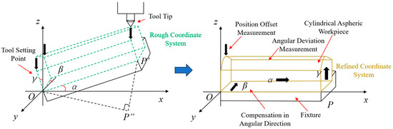
Figure 7.
Schematic diagram of high-precision coordinate system establishment method.
The compensation methodology for the rough coordinate system is outlined as follows: The measured origin functions as the origin of the coordinate system. Two points are measured along the X-axes and Y-axes and subsequently recorded in the robotic arm. Utilizing a three-point method, the robotic arm establishes the rough coordinate system, which serves as a foundation for subsequent angular deviation compensation.
Let the angular deviations measured along the X, Y, and Z axes be α, β, and γ, as shown in Equation (8).
In Equation (8), ∆hx, ∆hy and ∆hz are the dial gauge reading differences in X, Y and Z direction. dx, dy and dz are the distances traveled by the robotic arm along the X, Y, and Z axes, respectively. The rotation matrix Rxyz is then given by Equation (9).
The compensated point cloud coordinates are then given by Equation (10):
In Equation (10), (x0, y0, z0) denotes the theoretical initial point cloud coordinates of the cylindrical aspheric workpiece before polishing, defined in the workpiece’s design coordinate system. x0: Along the generatrix direction of the cylindrical aspheric surface (the direction of non-zero curvature). y0: Along the cylindrical axis (the direction of translational symmetry). z0: Perpendicular to the x0 − y0 plane (the direction of surface normal, critical for contact pressure control).
The physical representation of the robotic arm’s rudimentary construction of the workpiece coordinate system is illustrated in Figure 8a.
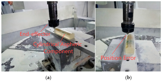
Figure 8.
Process diagram of rough coordinate system construction. (a) Rough construction of workpiece coordinate system by robotic arm. (b) Position error of rough coordinate system.
The initial coordinate system is defined by the tool tip located at the end-effector of the robotic arm. However, due to errors arising from manual tool setting and robotic arm motion, a position error ranging from micrometers to millimeters can occur at the origin after establishing the workpiece coordinate system with one corner of the workpiece designated as the origin and moving the robotic arm’s end-effector to this theoretical origin, as illustrated in Figure 8b. Consequently, there remains a need for further establishment of a high-precision coordinate system. This paper presents an iterative approach to establish a high-precision coordinate system utilizing advanced equipment aimed at continuously enhancing error compensation accuracy and ultimately fulfilling high-precision requirements.
First, using a digital dial gauge, based on the current rough coordinate system established by the robotic arm, directional error compensation is completed in the X, Y, and Z directions, as shown in Figure 9a,b. Based on the current workpiece size, the robotic arm moves 100 mm, 15 mm, and 100 mm in the X, Y, and Z directions, respectively, recording Δhx, Δhy, and Δhz. The angular deviations α, β, and γ are then calculated using Equation (8).
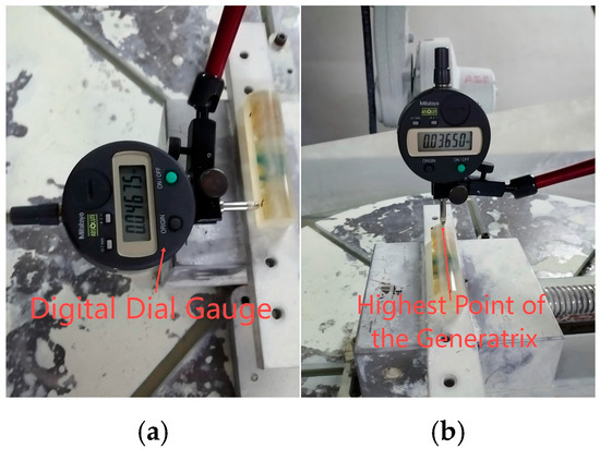
Figure 9.
Angle compensation diagram using dial gauge. (a) Angle compensation in X and Y directions. (b) Angle compensation in Z directions.
Due to the complexity associated with the distance between the dial gauge and the end-effector of the robotic arm, a laser tracker [17,18] is employed to calibrate this positional error and iteratively refine the directional error of the workpiece coordinate system, as shown in Figure 10. This process comprises three primary steps: point cloud planning, measurement, and fitting error analysis.
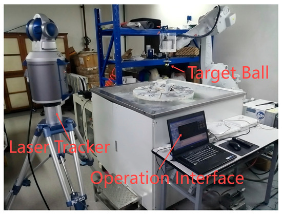
Figure 10.
Physical diagram of the laser tracker error compensation system.
The specific steps are as follows: First, attach the target ball of the laser tracker to the end-effector of the robotic arm. Next, plan the point cloud corresponding to the position of the end-effector. The laser emitter of the laser tracker transmits a laser signal that is reflected back to the receiver through the optical path of the target ball. This reflection is then converted into an electrical signal, which provides positional information regarding the target ball; in other words, it yields information about the position of the robotic arm’s end-effector. There exists a fixed relative position between the target ball and its associated end-effector, this relative positional data [19] accurately represents that of the end-effector itself.
The proposed calibration method for the robotic arm’s end-effector utilizing a laser tracker is characterized by its robustness, speed, and precision. This approach streamlines data analysis and significantly minimizes positioning errors of the robotic arm, thereby enhancing its overall accuracy.
4.3. Error Feedback Compensation Based on Profilometry
A profilometer is a widely used high-precision measuring instrument in polishing processes. Building upon the principles of CCOS theory, this section introduces an error feedback compensation model that utilizes profilometry data to inform the compensation process [20]. The proposed model employs a hierarchical regional compensation approach based on the extraction of feature value points. The core concept involves iteratively compensating for errors by leveraging the relationship between residual error and dwell time. Specifically, the residual error divided by the material removal rate yields the appropriate dwell time. By regulating dwell time, it is possible to achieve high-precision processing outcomes [21]. Various algorithms for determining dwell time include pulse iteration, matrix methods, and Fourier transform techniques, each tailored to specific processing environments. The solution for the dwell function entails deconvolution through residual removal combined with known material removal rates [22].
This section constitutes the third step of the three-step compensation method. First, the CMM is employed to measure the peak points of the cylindrical aspheric surface, thereby calibrating the reference consistency of the profilometer. Specifically, the highest points along different generatrices obtained from the CMM are used to offset the generatrix reference positions in the profilometer measurements. This process standardizes the generatrix reference for calculating the positional relationships of generatrix feature points. The methodology is grounded in the operational principle of the profilometer, which designates the highest point as the measurement reference. As detailed in the first step of the point cloud compensation, the generatrix deviations have already been quantified using the CMM.
The concept of feedback compensation is illustrated in Figure 11. Each polishing trajectory’s material removal is represented as a triangular pyramid within a three-dimensional space. The base width of the pyramid corresponds to the removal width associated with an individual polishing trajectory, while its height reflects the volume of material removed. Variations in polishing iterations lead to differing volumes of material removal. In the figure, Rc and Rsm represent the depth and width of material removal for a single polishing trajectory, respectively [12].
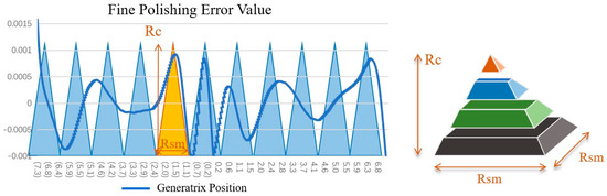
Figure 11.
Concept diagram of surface error feedback compensation.
Next, the calculation of the “triangular pyramid” is performed, that is, the calculation of the polishing compensation position and amount. The error compensation method based on the profilometer’s single generatrix measurement data includes the following: using derivatives to extract feature values (mainly maxima and minima); calculating the difference between these points and using the polishing head’s material removal rate for high-precision compensation. The second derivative of the measurement data is calculated using the difference method. At points with large second derivatives, small-range path overlap compensation polishing is applied, involving multiple paths. The number of paths n is related to the second derivative, ensuring the smoothness of the optical component. During the polishing process, the spherical polishing head is inspected for wear every 1 h using a laser profilometer. If the radius deviation exceeds 0.1 mm, the polishing head is replaced to avoid introducing additional contact errors into the error feedback compensation loop. The threshold of the second derivative is related to the polishing head’s contact removal area a, the target compensation error Δy0, and the material’s smoothness requirements. The compensation range Δx at the maximum point is related to the magnitude of the second derivative. This can be expressed as Equation (11):
In Equation (11), Δx: Compensation range at the maximum error point. It refers to the horizontal extension distance of the polishing path required to smooth the local high-error area (e.g., peaks or valleys on the cylindrical aspheric generatrix). Δy0: Target compensation error. It is the maximum allowable residual error after polishing. doverlap: Total width of small-range path overlap for single-point compensation. It is the sum of the overlapping widths of adjacent polishing paths in the local corrective area. The coefficients k1, k2, and k3 are influence factors derived from parameter experiments. n is the number of paths. D represents the diameter of the contact area between the polishing tool and the workpiece. The smoothness requirements, which also encompass low-frequency and mid-frequency error specifications [23], are dictated by the application domain of the component.
Next, compensation calculations are conducted. The model takes into account the offset impacts on the compensation position and rectifies fixed offset errors arising from measurement installation and fixture clamping. Iterative feedback compensation is based on the positional deviation observed in the previous compensation, as shown in Figure 12.
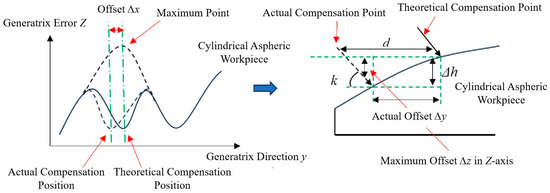
Figure 12.
Schematic diagram of feedback error compensation model based on measurement results.
Let the initial coordinates of the point cloud be denoted as (x0, y0, z0), while the actual machining position coordinates after tool compensation are represented as (x, y, z). In the direction of the vertical line corresponding to the cylindrical aspheric surface (i.e., along the X-axis of the robotic arm), it is observed that any offset has a negligible impact on the polishing process.
Let Δy and Δz represent the offset errors in the Y and Z directions, respectively. Given the robotic arm’s posture, along with the coordinates of two theoretical points and their corresponding actual measurements from the profilometer, the compensation parameter d can be calculated using the aspheric formula. This calculation is grounded in trigonometric relationships, as shown in Equation (12):
In Equation (12), Δy1 and Δy2 represent the distance deviations between the theoretical and actual compensation positions of two points from the previous measurement, with k1 and k2 denoting the tilt angles of the robotic arm at these respective positions. Consequently, the horizontal and vertical fixed offsets dhoriz and Δh can be computed. For measuring generatrices of cylindrical aspheric surfaces, three generatrices are selected, with their mean value taken as the final offset error. This model is based on spherical polishing head design and robotic arm posture control, effectively addresses the complex contact state of the tool head resulting from positional offsets during actual machining processes.
This paper utilizes an FFT-based approach for calculating the dwell function to ascertain the required polishing dwell time from known residual errors, as shown in Figure 13. The dwell function is derived from the relationship between residual error H and material removal rate P, resulting in the determination of dwell time T. Additionally, a coefficient Q is incorporated to mitigate negative values that may occur during iteration.
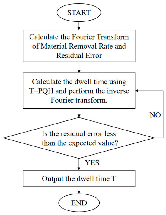
Figure 13.
Flowchart of dwell function calculation.
The generation of the robotic arm’s operational program, encompassing machining and compensation calculations, requires multiple iterative cycles. Each cycle incrementally enhances material removal, thereby improving surface accuracy as quantified by profilometric measurements. This relationship is depicted in Figure 14. Experimental results demonstrating the polishing effect after a single cycle are shown in Figure 15, confirming the model’s capability to quantitatively reduce peak irregularities and achieve higher surface precision.
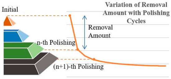
Figure 14.
Schematic diagram of the relationship between polishing cycles and removal amount.
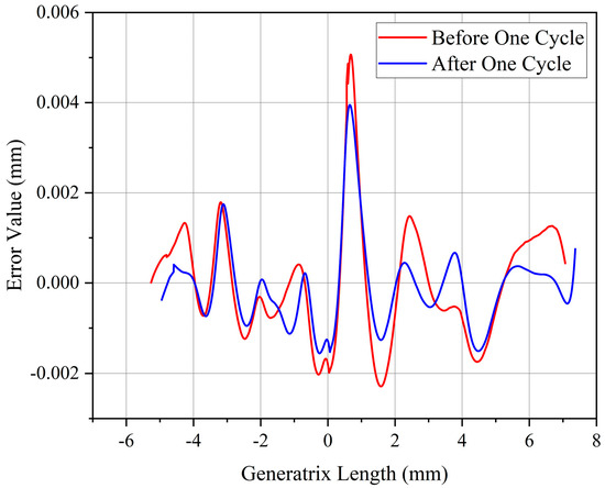
Figure 15.
Comparison data diagram for single polishing cycle.
5. Robotic Arm Polishing Experiment on Cylindrical Aspheric Workpiece
5.1. Experimental Equipment
The ABB IRB1600 (ABB Ltd., Zurich, Switzerland) uses an IRC5 controller with hybrid PID-force feedforward control. It synchronizes tool rotational speed and feed rate to maintain uniform pressure, ensuring consistent material removal. The polishing object is a cylindrical aspheric optical component fabricated from S-TiH53 glass. The upper surface of the cylinder features a complex curved profile. The total vertical length measures 200 mm, with an effective area requirement of 100 mm. The generatrix direction exhibits aspheric characteristics, described mathematically by Equation (13).
The parameters of the generatrix for the cylindrical aspheric surface are presented in Table 1. The generatrix is positioned at the origin, featuring a horizontal effective length of 15 mm.

Table 1.
Parameter table for cylindrical aspheric components.
The initial parameters of the generatrix and the reference position for measurement of the profilometer were established using a Hexagon Global Classic SR 575 CMM (Hexagon AB, Gothenburg, Sweden), which has a measurement range of 500 × 700 × 500 mm. The measurement instrument used for feedback compensation is the MarSurf LD260 Aspheric 2D profilometer (Mahr GmbH, Göttingen, Germany), which has a shape error measurement capability of ≤100 nm, as shown in Figure 16.
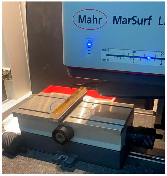
Figure 16.
MarSurf LD260 Aspheric 2D profilometer measuring the generatrix of workpiece.
5.2. Experimental Environmental Control
For temperature fluctuation control, the experiment was conducted in a Class 1000 cleanroom with a constant temperature of 23 ± 0.5 °C. A Pt100 high-precision temperature sensor (measurement accuracy: ±0.1 °C) was mounted near the workpiece fixture and the robotic arm base. Temperature data were recorded at 30 min intervals; if the fluctuation exceeded 0.3 °C, the experiment was paused until temperature stability was restored.
For polishing fluid stability control, A magnetic stirrer (300 revolutions per minute) is used to continuously stir the polishing liquid storage tank to prevent particle sedimentation.
To control tool wear, a regular inspection-replacement mechanism was established for the self-developed spherical polyurethane polishing head. After every 1 h of continuous polishing, the head was detached from the robotic arm and its surface morphology/radius were measured using a Keyence VK-X200 laser profilometer (Itasca, IL, USA) (accuracy: ±0.01 mm); If the radius deviation exceeded 0.1 mm or obvious scratches/abrasion were observed, the head was immediately replaced. This avoided uneven contact between the tool and workpiece.
5.3. Fixture and Tool Setting Error Compensation
To achieve micrometer-level polishing precision, this study employs a combination of UV adhesive bonding and clamping techniques. The component is securely bonded to an aluminum plate and held in place using a specialized fixture. This approach ensures repeatability at the micrometer level by effectively controlling manufacturing errors. It provides consistent positioning, facilitates easy loading and unloading, maintains stability, prevents damage to contact surfaces, and offers a cost-effective solution.
Tool setting aims to establish an accurate workpiece coordinate system based on the tool coordinate system. The tool setting process described in this paper consists of two primary steps: the preliminary establishment of the robotic arm’s workpiece coordinate system and the subsequent correction of any deviations in the workpiece coordinate system using a dial gauge. Following the methodology outlined in Section 4.2, a rough coordinate system is initially established. Upon completion, it is essential that the theoretical origin of the workpiece coordinate system aligns with the actual origin of the workpiece intended for machining. When the robotic arm moves to this designated origin, the origin deviation occurs as shown in Figure 17.
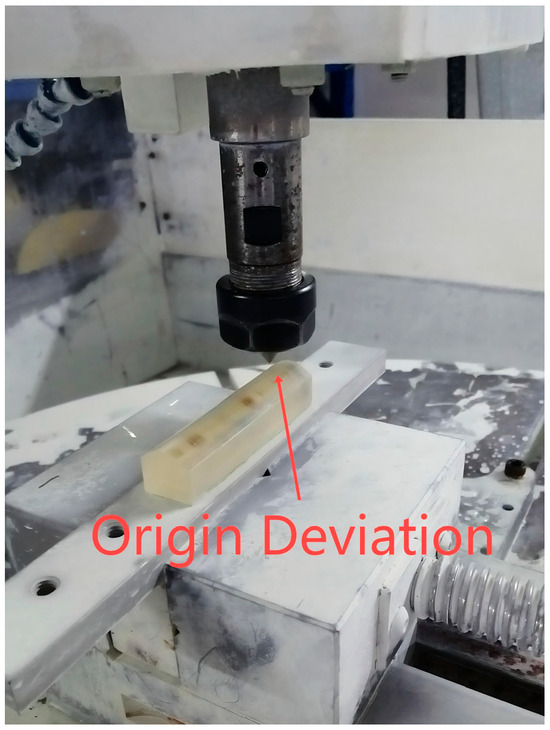
Figure 17.
Tool Setting Origin Deviation Phenomenon.
Without tool setting compensation, the accuracy error of the robotic arm reaches a millimeter level. By utilizing a digital dial gauge based on a rough coordinate system, directional error compensation is conducted in the X, Y, and Z directions to establish a preliminary refined coordinate system. The robotic arm is moved 100 mm, 15 mm, and 100 mm along the X, Y, and Z axes, respectively, while recording Δhx, Δhy, and Δhz. Subsequently, the angular deviations α, β, and γ are calculated using the aforementioned formulas. The specific operational procedure is shown in Figure 18a,b.
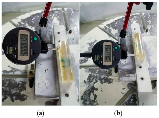
Figure 18.
Calculate deviation by moving in the Y-direction. (a) Reading before movement; (b) Reading after movement.
The results of the calibration for the rotation matrix and angular deviation, as derived from Equations (9) and (10), are presented in Table 2.
Table 2.
Compensation data table for angular deviation.
After the completion of tool setting, establishment of the coordinate system, and initial compensation, trial polishing was conducted. The resulting issues are illustrated in Figure 19.
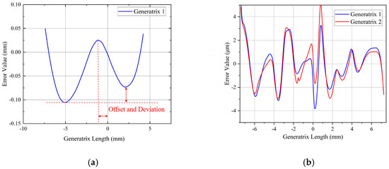
Figure 19.
Diagram of error phenomena in robotic arm polishing. (a) Diagram of aspheric generatrix angular offset results. (b) Diagram of tool setting error causing polishing processing deviation results.
The results indicate the presence of eccentricity and offset along the same aspheric generatrix. The piece exhibited skewing along the generatrix in the X-direction, as shown in Figure 19a. Additionally, its center position shifted towards the X-direction, suggesting that deviations in both X-axis displacement and rotation angle were still present.
Profile measurements taken along various generatrices of the cylindrical aspheric surface at 100 mm intervals in the vertical direction indicated a pitch angle deviation perpendicular to the X-axis, as shown in Figure 19b. Due to positioning errors, excessive polishing force resulted in damage to the optical component during actual contact polishing, as shown in Figure 20. Consequently, further high-precision compensation was implemented following the laser tracker error compensation procedure outlined in Section 4.2.
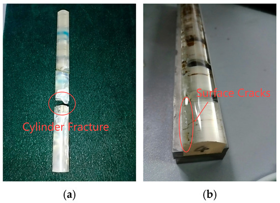
Figure 20.
Actual image of polishing processing accident. (a) Actual image of workpiece fracture. (b) Actual image of workpiece surface cracks.
5.4. Experimental Results and Discussion
The measured point cloud data were compensated for three angular errors using the least squares fitting method described earlier. The Mahr profilometer was employed to measure the surface profile of the workpiece after a single precision polishing cycle, as shown in Figure 21a. Subsequently, preliminary multi-cycle precision polishing was conducted, achieving certain standards for both surface finish and profile accuracy of the cylindrical aspheric test piece, as shown in Figure 21b.
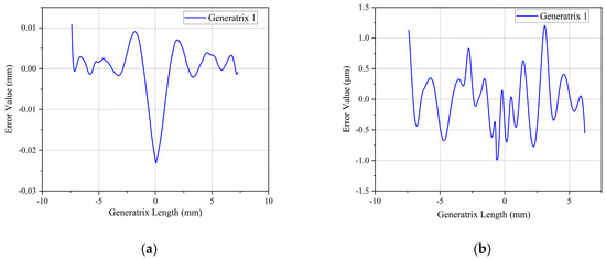
Figure 21.
Diagram of workpiece surface before and after initial fine polishing. (a) Before initial fine polishing. (b) After initial fine polishing.
To mitigate edge effect errors during polishing, this experiment adopted an approach of increasing both the raw material size and polishing area to ensure the dimensional accuracy of the target components. The error smoothing effect following preliminary polishing was inadequate to meet optical performance requirements in high-power laser applications. Therefore, utilizing the previously discussed theory, localized multi-path corrective polishing was performed. The final polished surface profile accuracy is shown in Figure 22a, while results from multiple polishing experiments on the workpieces are presented in Figure 22b.
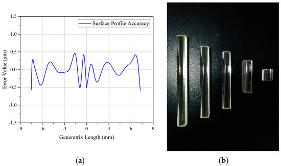
Figure 22.
Diagram of finished workpiece surface profile data and actual effect. (a) Diagram of final surface profile error data of workpiece. (b) Actual image of finished workpiece.
The figure illustrates that, within a 15 mm evaluation width, the surface PV value of the cylindrical aspheric surface in this experiment has achieved a level below 2 μm. All parameters satisfy the stringent requirements for high-power lasers, thereby validating the scientific and practical efficacy of the polishing system for optical components based on a six-degree-of-freedom robotic arm as described in this paper.
6. Discussion
This paper presents high-precision machining methods for complex optical components (e.g., cylindrical aspherics), centered on an integrated error compensation framework and complemented by a curvature-driven trajectory design. By integrating this supporting trajectory design and the core high-precision integrated error compensation framework, the efficiency and precision of robotic arm polishing are significantly enhanced. Experiments conducted on cylindrical aspheric components validate the effectiveness of the proposed methods, achieving a surface accuracy with PV value ≤ 2 μm.
Liu et al. [24]. from the Institute of Optics and Electronics, Chinese Academy of Sciences, employed a Stäubli robotic arm for small-tool polishing of hyperboloid surfaces, achieving a final surface figure error of PV 19.35 μm and RMS 2.25 μm. Our method demonstrates a 9.67-fold improvement in the PV value accuracy compared to their results. This comparison conclusively validates that our approach provides a superior and more precise solution for robotic arm polishing of symmetric complex curved surfaces, such as cylindrical aspherics.
Although validated on S-TiH53 glass, the core modules are geometry- and material-agnostic. For free-form optics, the generatrix extraction step can be replaced by 3-D iso-parametric sampling while keeping the overlap-model and compensation loop unchanged. For harder materials (e.g., sapphire), only the Preston coefficient and polishing pressure need re-calibration via the same single-point protocol. However, the performance of the proposed system is subject to certain limitations which outline directions for future inquiry. There remains potential for enhancing the accuracy of target processing. The motion accuracy of the robotic arm, approximately 20 μm, restricts the precision achievable in each processing stage. The profilometer utilized in the CCOS process exhibits a measurement error of 0.1 micrometer, which can become amplified with frequent usage, thereby affecting the polishing guidance. Additionally, environmental factors such as fluctuations in temperature, variability in polishing liquid concentration, and tool degradation further influence high-precision polishing outcomes. To compensate these effects during experimentation, measures were implemented including maintaining a stable temperature, incorporating a stirrer for the polishing liquid, and conducting regular maintenance on tools.
7. Conclusions
A robot polishing pipeline centered on three-step integrated error compensation and complemented by curvature-driven trajectory design was developed for cylindrical aspheric components. Surface figure accuracy PV ≤ 2 µm was achieved on S-TiH53 glass, surpassing existing robot-polished results by nearly one order of magnitude. The modular framework is readily extendable to free-form geometries and hard optical materials, laying a foundation for next-generation high-power laser and precision optical systems.
Author Contributions
Conceptualization, R.L. and L.S.; methodology, R.L. and L.S.; software, J.X.; validation, Y.L., J.X. and L.S.; formal analysis, Y.W.; investigation, R.L. and J.X.; resources, R.L.; data curation, Y.W.; writing—original draft preparation, Y.L., J.X. and Y.W.; writing—review and editing, Y.L., R.L., J.X., Y.W. and L.S.; visualization, Y.L. and Y.W.; supervision, Y.L.; project administration, L.S.; funding acquisition, L.S. All authors have read and agreed to the published version of the manuscript.
Funding
This work was supported by the fellowship of National Natural Science Foundation of China (grant number 52293405, 52405511); China Postdoctoral Science Foundation (grant number 2020T130511); Shaanxi Provincial Natural Science Foundation (grant number 2022JQ-409); Shaanxi Provincial Major Science and Technology Projects (grant number S2020-ZDZX-ZNZC-0002); Shaanxi Provincial Key Research and Development Program (grant number 2021LLRH-01-01); Aviation Science Fund (grant number 20240008070001).
Data Availability Statement
The data presented in this study are available on request from the corresponding author.
Conflicts of Interest
Authors Yao Liu, Ruiliang Li and Jingjing Xie were employed by the Qinchuan Machine Tool & Tool Group Corp. The remaining authors declare that the research was conducted in the absence of any commercial or financial relationships that could be construed as a potential conflict of interest.
References
- Yuan, J.; Lyu, B.; Hang, W.; Deng, Q. Review on the progress of ultra-precision machining technologies. Front. Mech. Eng. 2017, 12, 158–180. [Google Scholar] [CrossRef]
- Wang, Z.; Shi, C.; Zhang, P.; Yang, Z.; Chen, Y.; Guo, J. Recent Progress of Advanced Optical Manufacturing Technology. J. Mech. Eng. 2021, 57, 23–56. [Google Scholar]
- Deng, Y.; Wang, G.; Yue, X.; Zhou, K. A Review of Robot Grinding and Polishing Force Control Mode. In Proceedings of the 19th IEEE International Conference on Mechatronics and Automation (IEEE ICMA), Guilin, China, 7–10 August 2022; Electronic Network: West Yorkshire, UK, 2022; pp. 1413–1418. [Google Scholar]
- Muruganantham, V.R.; Thirumalaimuthukumaran, M.; Akila, K.; Bhuvanesh, D.; Praveen, R. Implementation of an Automatic Polishing Process with a Conveyor Mechanism. Appl. Mech. Mater. 2024, 920, 129–139. [Google Scholar] [CrossRef]
- Li, Z.-L.; Wang, R.; Zhang, X.-Q.; Zhu, L.M. B-spline surface approximation method for achieving optimum dwell time in deterministic polishing. J. Mater. Process. Technol. 2023, 318, 118031. [Google Scholar] [CrossRef]
- Huang, T.; Zhao, D.; Cao, Z.-C. Trajectory planning of optical polishing based on optimized implementation of dwell time. Precis. Eng.-J. Int. Soc. Precis. Eng. Nanotechnol. 2020, 62, 223–231. [Google Scholar] [CrossRef]
- Peng, Y.; Shen, B.; Wang, Z.; Yang, P.; Yang, W.; Bi, G. Review on polishing technology of small-scale aspheric optics. Int. J. Adv. Manuf. Technol. 2021, 115, 965–987. [Google Scholar] [CrossRef]
- Fan, C.; Xu, K.; Zhang, L.; Yuan, Q.; Wang, Q.; Wanga, K.; Sun, L. Kinematic Planning and In-Situ Measurement of Seven-Axis Five-Linkage Grinding and Polishing Machine Tool for Complex Curved Surface. Mach. Sci. Technol. 2022, 26, 203–228. [Google Scholar] [CrossRef]
- Kordonski, W.I.; Jacobs, S.D. Magnetorheological finishing. Int. J. Mod. Phys. B 1996, 10, 2837–2848. [Google Scholar] [CrossRef]
- Wang, Y.; Dai, C.; Li, W.; Meng, X.; Dong, H.; Wang, P. Polishing an off-axis aspheric mirror by ion beam figuring. In Proceedings of the 8th International Symposium on Advanced Optical Manufacturing and Testing Technologies—Advanced Optical Manufac-turing Technologies, Suzhou, China, 26–29 April 2016. [Google Scholar]
- Chen, X.; Yu, H.; Pan, H.; Chen, L.; Liang, X.; You, H. A Layered Split Polishing Path Planning Method Used in AWJP Based on Optical Glass Surface Morphology. Int. J. Precis. Eng. Manuf. 2025, 26, 269–282. [Google Scholar] [CrossRef]
- Bouland, C.; Urlea, V.; Beaubier, K.; Samoilenko, M.; Brailovski, V. Abrasive flow machining of laser powder bed-fused parts: Numerical modeling and experimental validation. J. Mater. Process. Technol. 2019, 273, 116262. [Google Scholar] [CrossRef]
- Feng, Y.; Cheng, H.; Wang, T.; Dong, Z.; Tam, H.-Y. Optimal strategy for fabrication of large aperture aspheric surfaces. Appl. Opt. 2014, 53, 147–155. [Google Scholar] [CrossRef] [PubMed]
- Zhao, Q.; Zhang, L.; Han, Y.; Fan, C. Polishing path generation for physical uniform coverage of the aspheric surface based on the Archimedes spiral in bonnet polishing. Proc. Inst. Mech. Eng. Part B J. Eng. Manuf. 2019, 233, 2251–2263. [Google Scholar] [CrossRef]
- Mao, J.; Ni, L.; Xiang, B.; Shu, L. Position Error Modeling and Compensation for Robot Bonnet Polishing. Mech. Sci. Technol. Aerosp. Eng. 2023, 42, 724–729. [Google Scholar]
- Tam, H.Y.; Zhang, L.; Hua, M. Material removal by fixed abrasives following curved paths. Proc. Inst. Mech. Eng. Part B J. Eng. Manuf. 2004, 218, 713–720. [Google Scholar] [CrossRef]
- Guo, J.; Wang, D.; Fan, R.; Chen, W.; Zhao, G. Kinematic calibration and error compensation of a hexaglide parallel manipulator. Proc. Inst. Mech. Eng. Part B J. Eng. Manuf. 2019, 233, 215–225. [Google Scholar] [CrossRef]
- Sun, T.; Zhai, Y.; Song, Y.; Zhang, J. Kinematic calibration of a 3-DoF rotational parallel manipulator using laser tracker. Robot. Comput. Integr. Manuf. 2016, 41, 78–91. [Google Scholar] [CrossRef]
- Shao, X.; Ji, L.; Zou, H.; Xie, Y. Parameter calibration method for manipulators based on laser displacement measurement. J. Beijing Univ. Aeronaut. Astronaut. 2022, 48, 2281–2288. [Google Scholar]
- Wan, Y.; Shi, C.; Yuan, J.; Wu, F. Control method of polishing errors by dwell time compensation. High Power Laser Part. Beams 2011, 23, 97–100. [Google Scholar] [CrossRef]
- Zhang, J.; Wang, H. Generic model of time-variant tool influence function and dwell-time algorithm for deterministic polishing. Int. J. Mech. Sci. 2021, 211, 106795. [Google Scholar] [CrossRef]
- Wang, Y.; Zhang, Y.; Kang, R.; Ji, F. An Elementary Approximation of Dwell Time Algorithm for Ultra-Precision Computer-Controlled Optical Surfacing. Micromachines 2021, 12, 471. [Google Scholar] [CrossRef]
- Wang, B.; Tie, G.; Shi, F.; Song, C.; Guo, S. Research on the influence of the non-stationary effect of the magnetorheological finishing removal function on mid-frequency errors of optical component surfaces. Opt. Express 2023, 31, 35016–35031. [Google Scholar] [CrossRef] [PubMed]
- Liu, H.; Wan, Y.; Zeng, Z.; Xu, L.; Zhao, H.; Fang, K. Freeform surface grinding and polishing by CCOS based on industrial robot. In Proceedings of the 8th International Symposium on Advanced Optical Manufacturing and Testing Technologies—Advanced Optical Manufacturing Technologies, Suzhou, China, 6–29 April 2016. [Google Scholar]


Disclaimer/Publisher’s Note: The statements, opinions and data contained in all publications are solely those of the individual author(s) and contributor(s) and not of MDPI and/or the editor(s). MDPI and/or the editor(s) disclaim responsibility for any injury to people or property resulting from any ideas, methods, instructions or products referred to in the content. |
© 2025 by the authors. Licensee MDPI, Basel, Switzerland. This article is an open access article distributed under the terms and conditions of the Creative Commons Attribution (CC BY) license (https://creativecommons.org/licenses/by/4.0/).