In this section, we detail the mechanical architecture and the operational principle of the underactuated rigid–flexible coupled gripper (U-RFCG), establishing the foundation for its functionalities. Building upon this design, we present a combined static and kinematic analysis, the conceptual design of the interfacial microstructure, and a systematic performance evaluation encompassing single-finger contact force measurement and holistic gripper grasping tests.
3.1. Mechanical Design
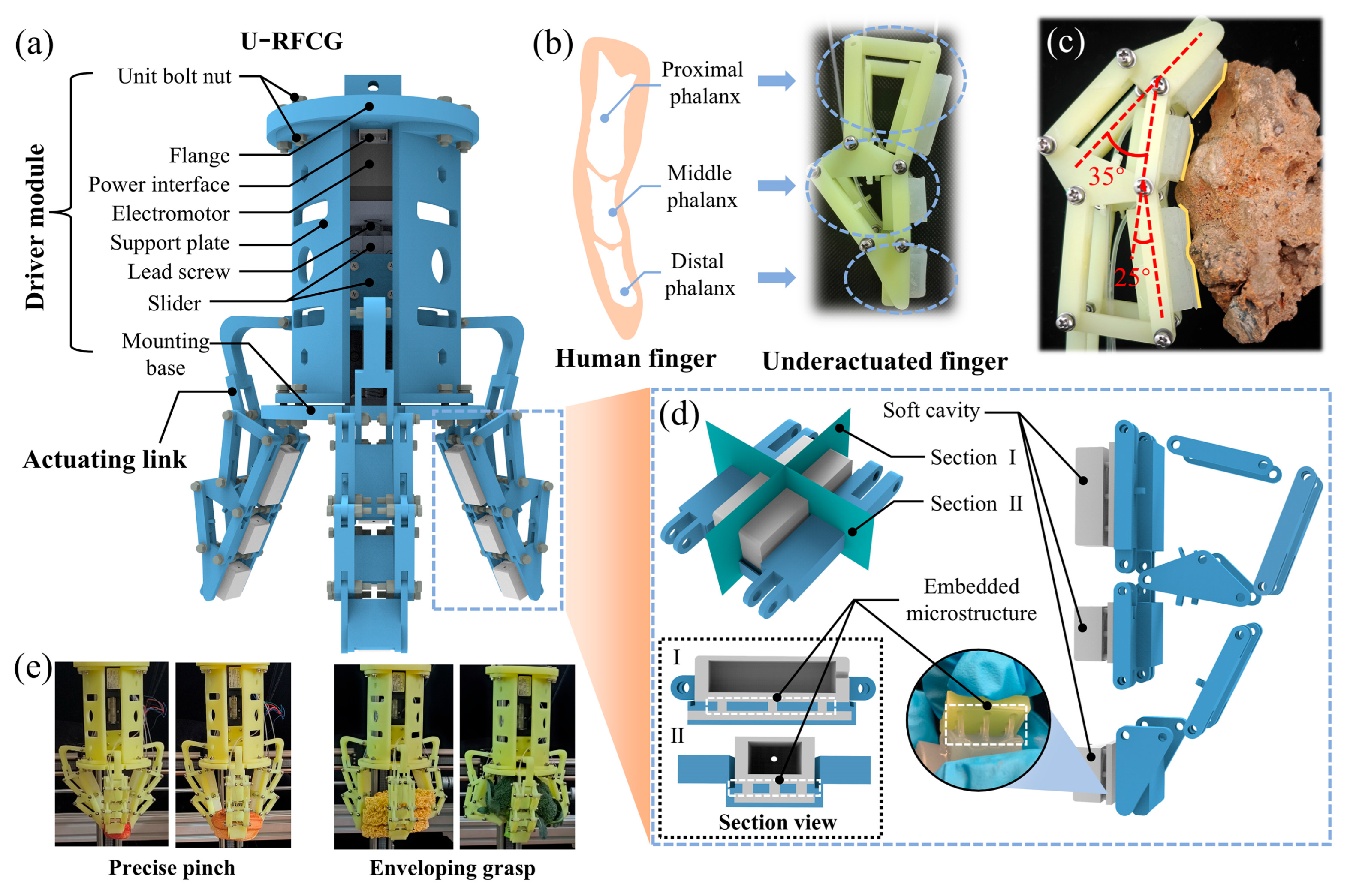
Figure 1a illustrates the overall architecture of the underactuated rigid–flexible coupled gripper, which is systematically composed of three core components: the drive module, the linkage mechanism, and the underactuated fingers. The lead screw motor integrated within the drive module serves as the power source, transmitting torque and linear motion to grasping region via a rigid underactuated linkage. This precise power transmission enables coordinated finger movement, facilitating flexible grasping actions and forming the basis for the gripper’s fundamental operational capability.
As shown in
Figure 1b, each finger of the U-RFCG consists of a rigid segment and a flexible segment. The rigid part adopts a three-segment underactuated linkage structure inspired by the anatomy of the human finger. Specifically, the rigid segment is divided into three sequentially connected sections corresponding to the proximal, middle, and distal phalanges of a human finger. This bio-inspired design allows the finger to autonomously adjust its posture upon contact with a target object. During grasping, the underactuated mechanism enables the phalanges to adaptively envelop the contour of objects, while the flexible structure attached to the rigid phalanges prevents direct collision and ensures conformal surface contact. This design enhances the compliance of the gripper through the passive adaptability of the underactuated rigid linkage, while the flexible contact interface composed of soft materials disperses contact forces through elastic deformation, preventing localized stress concentration and thereby protecting fragile objects from damage. As shown in
Figure 1c, when grasping an irregularly shaped stone, the underactuated mechanism and the flexible cavity work synergistically to conform to its rugged surface. The underactuated structure, through linkage transmission, guides each phalanx to self-adjust joint angle for conducting gripping movements, allowing the finger contours to initially align with the stone’s protrusions and recesses. The flexible cavity then undergoes adaptive deformation, filling the micro-gaps between the phalanges and the stone surface to achieve tight conformity. As shown in
Figure 1d, to further improve adaptability and interactive safety, a cavity structure and an embedded microstructure are innovatively incorporated into the flexible part of each finger. The internal cavity within the flexible structure provides the necessary space for compensatory deformation upon contact. This deformability allows the flexible segment to conform to the surface of the object during grasping, distributing contact pressure and thereby better protecting the object from damage. The embedded microstructure, made of high-toughness polymer material, is distributed at the interface between the rigid phalanges and the flexible segment, firmly coupling the two structures despite their significantly different mechanical moduli.
Benefiting from the dexterous underactuated structure, the U-RFCG is empowered with two universal grasping modes, precise pinching and envelope grasping, to handle objects of varying sizes and shapes, as illustrated in
Figure 1e. Pinch grasping is primarily effective for small, lightweight objects such as fresh strawberries or small bread rolls. In this mode, only the distal phalanges come into contact with the object, mimicking the “pinching” action of human fingers. In contrast, envelope grasping is designed for large or irregularly shaped objects, such as irregularly stacked instant noodle boxes or loosely structured cauliflower heads. When this mode is activated, the gripper first adjusts the initial angles of the three fingers via the drive module to surround the target object from multiple directions. As the fingers approach the object, the underactuated linkage drives the proximal, middle, and distal phalanges to rotate at different angles according to the contour of the object. Simultaneously, the flexible segments deform upon contact, filling gaps between the rigid phalanges and the object surface. This multi-segmented structure, with its multi-point conforming mechanism, fully restrains the target object. Thus, it effectively prevents the grasped object from slipping or tilting during grasping, and enables stable handling even for complex, irregular shapes.
3.2. Design of Linkage-Based Structure of Underactuated Rigid–Flexible Coupled Finger
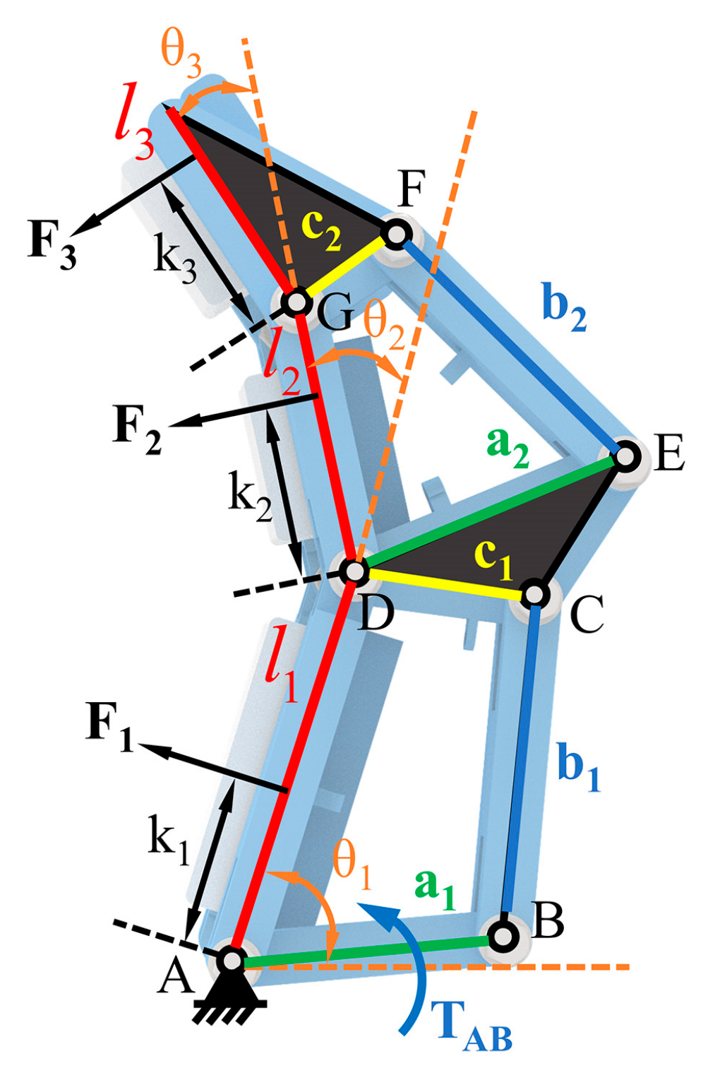
The underactuated rigid–flexible coupled finger employs a linkage-based actuating mechanism, which consists of the proximal phalanx, middle phalanx, and distal phalanx. When actuated, the drive module delivers torque to link AB, which subsequently transmits force through the linkage mechanism to each phalanx, eventually exerting it on the grasped object. Whether in fingertip pinching or enveloping grasping mode, the finger can effectively mimic the grasping behavior of a human finger throughout the entire interaction process.
Firstly, a static model is established to reveal the influence of structural parameters on the grasping contact force. As shown in
Figure 2, the lengths of the proximal, middle, and distal phalanges
are biomimetically set to 1.25:1:0.8 (45 mm, 30 mm, 24 mm, respectively), referring to the length proportions of human finger phalanges. The distances between the contact points and corresponding rotation axes during grasping are
.
When pinching with the fingertip, the proximal and middle phalanges remain relatively stationary. Treating the entire finger as a rigid body, we apply the principle of moment balance to derive the relationship between the fingertip contact force
,
, and the relative rotation angle
(detailed in
Text S1 and Figure S2).
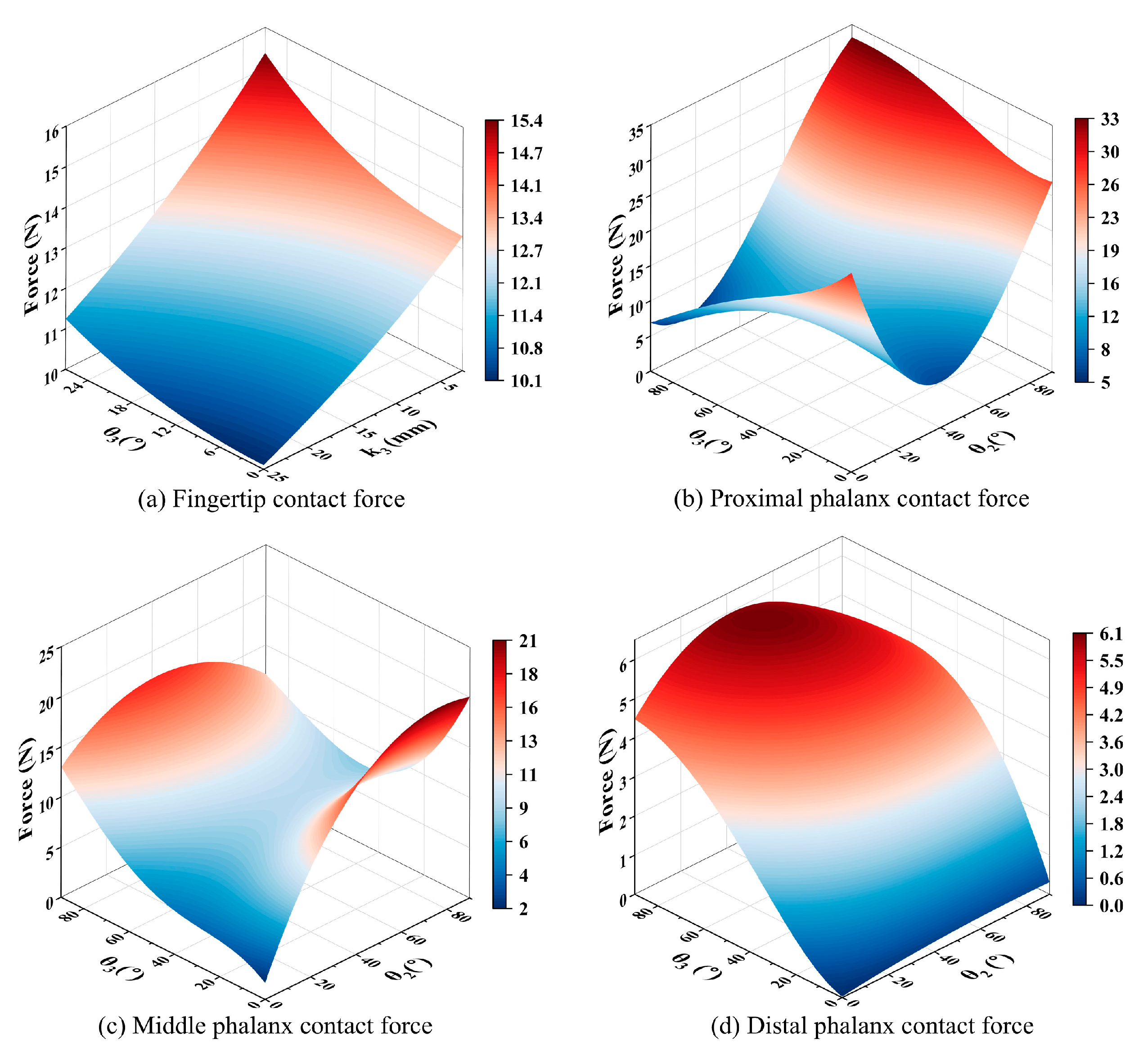
Based on the theoretical model, we substitute relevant parameters for the numerical solution and obtain the results under an input torque of 1000 N·mm (
Figure 3a). Clearly, the contact force exhibits a positive correlation with the angle
, and it is negatively correlated with
, which is a trend consistent with the behavior observed during human finger pinching. In enveloping grasping mode, each phalange adaptively conforms to the shape of target. According to the principle of virtual work (
) [
34], we can obtain the variation in contact force:
where
are expressions related to parameters
(detailed in
Text S2 and Figure S2). Furthermore, to ensure accuracy and stability during grasping, we optimize the dimensions of the linkages
with objective functions:
and
. We aim to maximize the total contact force while minimizing the differences in contact forces among the phalanges. Subsequently, a multi-objective genetic algorithm is utilized for solving. We select the optimal design parameters from the resulting Pareto front, which represents a collection of non-dominated solutions, by summing the values of two optimization objectives, sorting them in descending order, and taking the median value to balance both performance goals. To minimize the impact of calculation error in a single optimization run, the final results are derived by averaging the outcomes from 10 independent optimization trials, followed by rounding to determine the definitive values, as summarized in
Table 1. Finally, the optimal parameters of
are determined as {31 mm, 38 mm, 20 mm, 32 mm, 35 mm, 13 mm}. Based on this, we conduct a numerical simulation of the contact force model under full enveloping conditions. The results (
Figure 3b–d) demonstrate a sequential decrease in contact force from the proximal to the distal phalanx, which is a distribution pattern consistent with the biomechanical behavior observed in human finger grasping.
Kinematically, the underactuated finger is powered by a single actuation element. Based on the parameter set
and linkage dimensions, a well-defined kinematic model can be established.
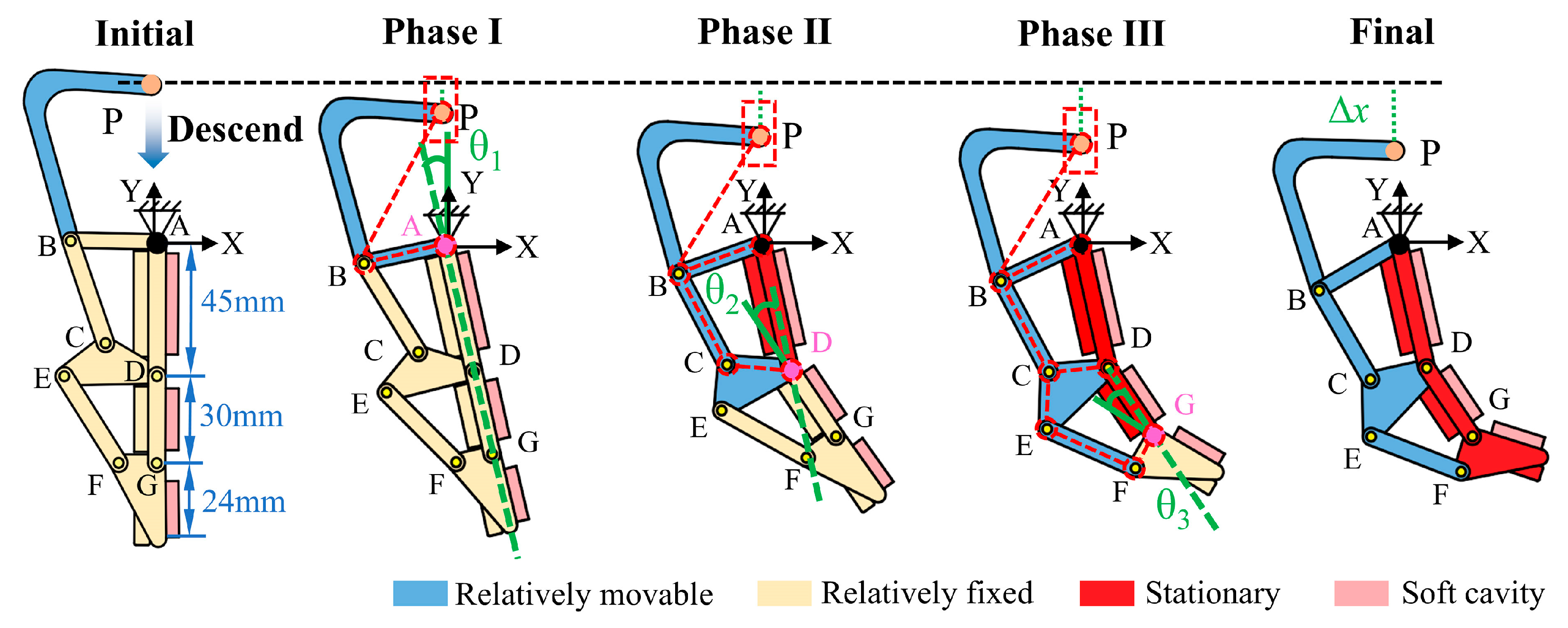
Figure 4 shows the entire process of the underactuated finger achieving enveloping contact. The rotation axis A on the proximal phalanx is fixed to the base of the actuation module. And the connecting link PB, actuated by the motor, undergoes displacement
and transmits motion through the linkage mechanism. Since the underactuated structure has more than one degree of freedom, the motion of the mechanism is indeterminate. Therefore, to accurately analyze the kinematic characteristics of the finger, we divided the entire process into three stages. In phase I, all phalanges rotate together around rotation axis A following
, with the entire finger functioning as a slider–rocker mechanism. After the proximal phalanx contacts the object, phase II begins. The proximal phalanx is fixed, and the middle and distal phalanges rotate together around rotation axis D, with the finger becoming a combination of a slider–rocker and a double-rocker mechanism. In phase III, once the middle phalanx contacts and becomes fixed relative to the object, the distal phalanx rotates independently around axis G. The finger functions as a multi-linkage mechanism possessing a single degree of freedom. Upon contact of the distal phalanx with the object, the underactuated finger successfully completes the enveloping grasp. To construct a comprehensive kinematic model, a coordinate system
-
is defined on the lateral plane of the finger, with the fixed point A designated as the origin, in order to precisely characterize the positions of key points. To simplify the analysis, the initial position of each phalanx is aligned vertically to minimize kinematic interference from adjacent phalanges during motion.
As shown in
Figure 5, using the closed-loop vector method [
35], we obtained the kinematic characteristics of the phalanges (detailed in
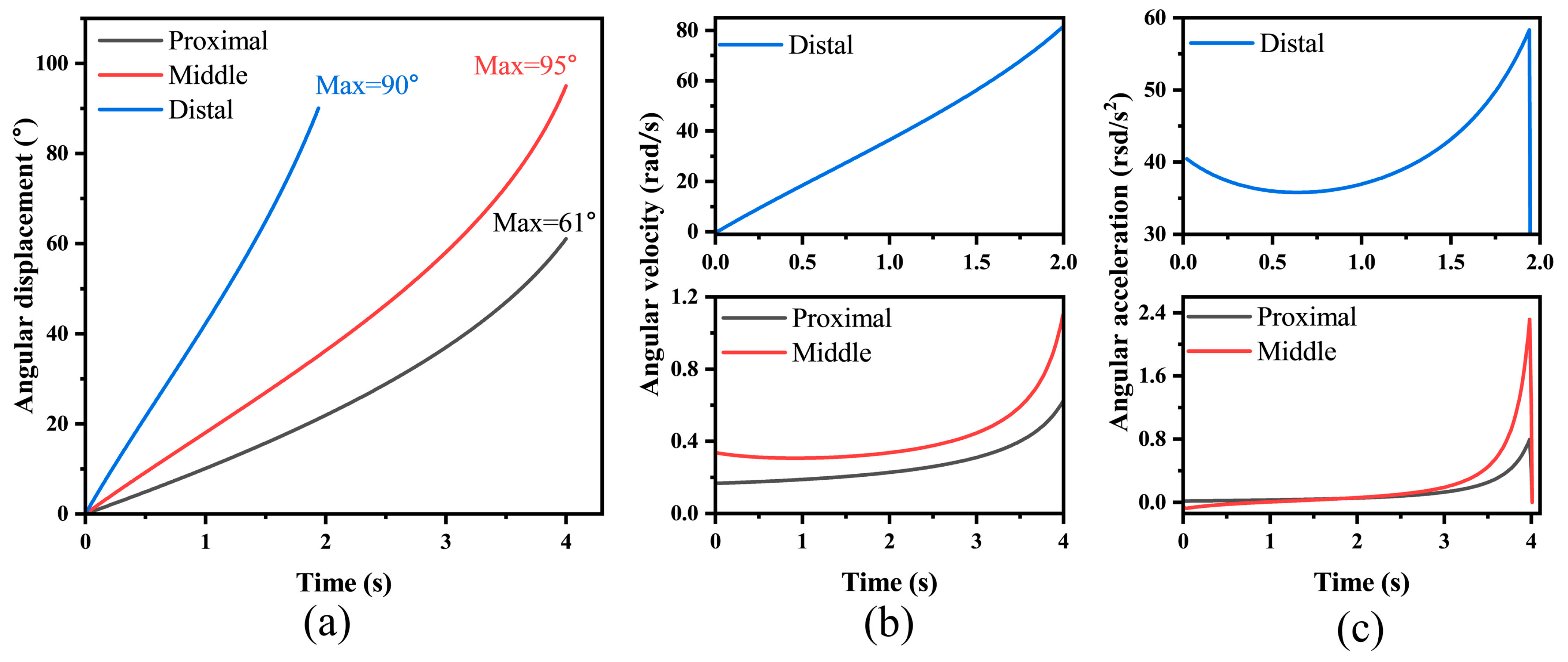
Text S3). The results indicate a progressive increase in motion intensity from the proximal to the distal end, with the distal phalanx exhibiting significantly greater flexibility compared to the proximal and middle phalanges, which demonstrates highly biomimetic behavior. Moreover, the motion profiles of the phalanges remain continuous, showing no abrupt changes in displacement or velocity, which confirms the smooth operation of the designed underactuated finger. This stability is essential for achieving reliable and precise grasping performance in robotic applications.
3.3. Investigation of Microstructure Toughening Mechanism
The interface between the rigid skeleton and the flexible cavity is critical in rigid–flexible coupling design. However, the significant mismatch of elastic modulus between the two distinct materials presents a challenge for firm connection. Since the elastic modulus of the rigid skeleton is significantly higher than that of the flexible cavity, a substantial discrepancy in their deformation capacities arises when the structure is subjected to external forces. Specifically, the rigid material exhibits minimal deformation, whereas the flexible material is prone to significant deformation. This deformation incompatibility directly induces the occurrence of stress concentration at the interfacial junction. Over time, the prolonged action of external forces leads to the continuous accumulation of concentrated stress, which ultimately impairs the interfacial bonding strength and triggers problems such as interfacial delamination. Consequently, the connection between the rigid skeleton and the flexible cavity fails, resulting in a significant reduction in the stability and reliability of the rigid–flexible coupling structure.
The rigid–flexible coupling mechanism of the human finger offers valuable inspiration for addressing the aforementioned challenges. As shown in
Figure 6a, in the structure of the human finger, the rigid bones and flexible skin achieve efficient and stable coupling through unique connecting units known as fibrous septa. Specifically, the phalanges possess a relatively high elastic modulus, while the outer wrapping skin is soft and deformable, with a modulus much lower than that of the phalanges. Between these two structures with significantly different properties, dense fibrous septa extend radially from the outer surface of the phalanges to the skin, forming a robust connection system. Emulating this natural solution, we introduced a micropillar array to serve as an intermediate layer between the rigid skeleton and the flexible cavity. As shown in
Figure 6b, the micropillars, monolithically integrated with the flexible cavity, are fully embedded into the rigid substrate, thereby ensuring a firm anchor. This type of connection can effectively disperse the stress generated by the deformation difference between the two components, prevent excessive stress concentration at the interface, and thereby avoid the occurrence of slippage or even detachment.
The dimensional parameters of the micropillar structure significantly impact its mechanical properties. Therefore, we performed tests on samples with varying structures using a tensile apparatus (
Figure S4) to identify the optimal structural dimensions that satisfy the coupling criteria of the rigid framework and the flexible component. As shown in
Figure 7a, we systematically investigated the tensile force response behavior of the structure under different tensile displacements with the core dimensional parameters of the micropillar structure, including diameter, height, and array density. To precisely capture differences in mechanical responses across distinct deformation stages, the tensile distance was set to range from 2 mm to 10 mm, with an equal interval of 2 mm. Meanwhile, the array density was configured into three typical layouts, including 1 × 1, 2 × 2, and 3 × 3, to quantify how density variations affect the overall tensile performance of the micropillar array (
Figure S5). The results indicate that under the same tensile displacement, the tensile force increases with both the enlargement of the micropillar diameter D (
Figure 7b) and the increase in the number of micropillars in the array (
Figure S6). This phenomenon can be attributed to the expanded load-bearing cross-sectional area of individual micropillars and the superimposed load-bearing effect of multiple micropillars.
Furthermore, to characterize the coupling effect of diameter and height and avoid limitations from focusing on a single parameter, we explored the influence of aspect ratio (H/R) on performance. As shown in
Figure 7c, when the tensile displacement is 2 mm, the difference in tensile force among varying H/R values is minimal. However, as the tensile displacement gradually increases, the discrepancy in tensile force under differing H/R conditions becomes more pronounced, with an overall trend of decreasing tensile force as H/R increases. It follows that micropillars with a smaller H/R exhibit higher rigidity, which enables them to demonstrate superior resistance to deformation under stress and effectively prevent slippage at the rigid–flexible coupling interface. By synthesizing the test results and adapting them to the actual dimensions of the rigid framework, the optimal parameters for the micropillar structure were finally determined: a micropillar diameter of 2 mm, a height of 2 mm, and an array density arranged in a 3 × 3 configuration. This design not only guarantees the stability of the rigid–flexible coupling interface under stress but also precisely aligns with the dimensional requirements for integration into the rigid structure.
Additionally, a comprehensive validation of the relevant properties of the determined micropillar structure was conducted. Firstly, we characterized the variation in tensile force during the “loading–unloading” process of the micropillar structure under a 10 mm tensile distance, with the results shown in
Figure 7d. Obviously, the mechanical behavior of the micropillar structure differs between the stretching stage and the recovery stage, exhibiting hysteretic characteristics. By calculating the area of the hysteresis loop, we found that the energy consumed by the micropillar structure in one “loading–unloading” cycle is 0.6087 mJ. This indicates that the micropillar structure has a certain energy dissipation capacity. In addition, durability constitutes a critical performance metric for practical applications. As illustrated in
Figure 7e, under small tensile displacements (2 mm and 4 mm), the tensile force stabilizes at approximately 0.75 N and 1.25 N, respectively. Nevertheless, with an increase in tensile displacement, the stability of the tensile force gradually diminishes, accompanied by a consistent elevation in peak force. Morphological observations of the micropillar structure reveal that severe deformation occurs under large displacements, which implies a potential compromise in its fatigue life during prolonged service. Consequently, we conducted 100 cyclic loading–unloading experiments on the micropillar structure at a tensile distance of 10 mm. The results indicated an attenuation rate of only 2.94% (
Figure 7f), demonstrating that the micropillar structure possesses commendable durability.
3.4. Performance Characterization of the Underactuated Finger
Uniform contact force distribution during object grasping represents a critical feature of underactuated rigid–flexible coupled fingers. This characteristic not only substantially influences the grasping stability of the gripper system but also effectively mitigates localized stress concentration when manipulating deformable or fragile objects, thereby preventing potential damage induced by excessive force exertion from individual finger segments. To quantitatively evaluate this property, we conducted experimental measurements simulating realistic object-contact scenarios. As illustrated in
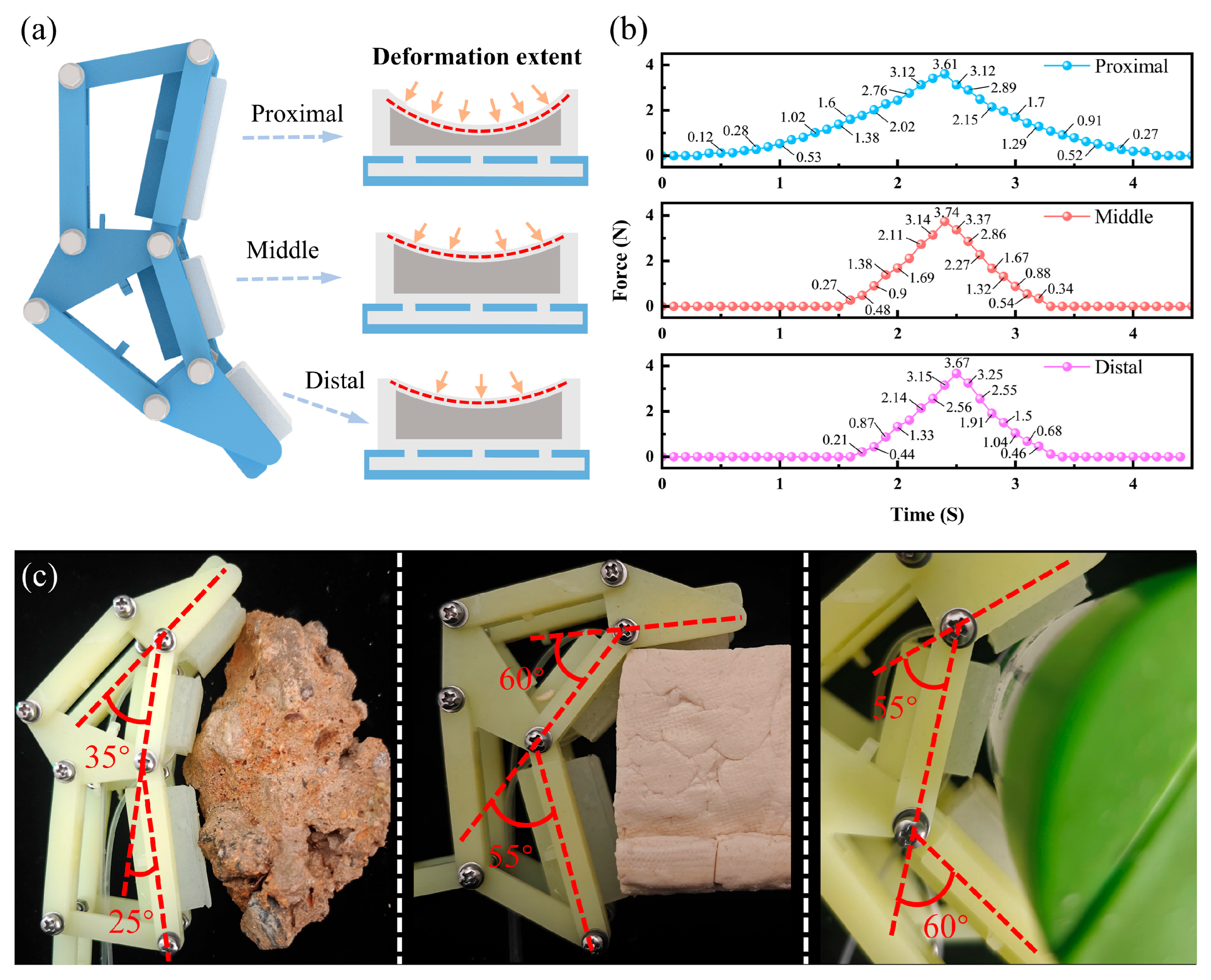
Figure 8a, the experimental configuration involved a dynamometer fixed at a predetermined position to establish contact with the finger mechanism when the three phalanges were vertically aligned. The driving slider was programmed to descend at a constant velocity of 2 mm/s while recording the corresponding force data (the experimental setup is detailed in
Supplementary Figure S7). Sequential measurements of contact forces were performed for the proximal, medial, and distal phalanges, with results presented in
Figure 8b. Across 18 complete contact–separation cycles, the recorded mean peak contact forces for each phalanx were 3.58 N, 3.66 N, and 3.5 N, respectively. All phalanges exhibited low variability in contact force measurements, with coefficients of variation not exceeding 5.2%. The proximal, middle, and distal phalanges achieved values of 4.3%, 5.1%, and 3.8%, respectively, indicating highly consistent and reliable experimental data. Meanwhile, this narrow force distribution confirms highly consistent force output characteristics among different phalanges during contact events. Furthermore, the force profiles exhibited remarkable stability throughout cyclic testing, devoid of anomalous fluctuations, which substantiates predictable and controllable force transmission behavior during finger–object interaction.
Notably, we found that the force variation curve of the proximal phalange is significantly smoother than those of the middle and distal phalanges throughout each cycle. This observation confirms an excellent buffering effect of the proximal phalange. As shown in
Figure 9a, in the enveloping grasping mode, the soft components of all phalanges gradually deform as contact progresses. The proximal phalange, which makes initial contact with the object, experiences a longer duration of contact. This extension allows the soft component of the proximal phalange sufficient space for deformation, enabling it to dissipate instantaneous forces effectively. Consequently, this results in a more stable force output curve. This buffering characteristic significantly mitigates the instantaneous peak of contact force during grasping and reduces the risk of cracks or fragmentation in fragile targets caused by localized stress concentrations. Thus, it enhances the applicability and operational safety of the mechanical gripper when handling brittle materials. To further validate this, we randomly selected one cycle from force variation data of each phalange for analysis. As shown in
Figure 9b, the force variation curves of all phalanges exhibit gentle variation with minimal fluctuations. This indicates that the flexible components of each phalanx provide buffering. Among these, the buffering effect of the proximal phalange is particularly pronounced, and this aligns with previous findings that greater deformation in the proximal phalange enhances buffering capacity of this phalange. A deeper comparison of contact-phase force changes reveals that contact forces of the three phalanges differ only slightly at each sampling point, and they remain nearly consistent overall. This underscores that the gripper achieves a uniform force distribution via inter-phalange synergistic interaction in enveloping grasping, which effectively prevents excessive force concentration on any single phalange.
To investigate the adaptability of a single finger to different object surfaces, we conducted experiments in which the finger was brought into contact with objects of varying shapes. During the tests, we observed both the morphological changes in the finger and its enveloping effect on the objects. As illustrated in
Figure S8, three representative object types were selected for evaluating the finger’s adaptive performance: irregular stones, 40 mm × 60 mm tofu blocks (regular square shape), and cylindrical bottles with a 50 mm diameter (regular circular shape). The results, presented in
Figure 9c, show that when interacting with a rock with a rugged surface, the underactuated structure adjusts the joint angles to 25° and 35°, allowing the flexible component to fit into the rock’s grooves and protrusions for a tight enclosure. For the regular square tofu blocks and cylindrical bottles, the underactuated structure modifies the joint angles appropriately to match the square edges and cylindrical curvature, respectively, ensuring effective contact with the object surfaces.
In summary, whether the target object is an irregular stone, a square tofu block, or a cylindrical bottle, the underactuated structure works in conjunction with the flexible components to achieve optimal surface fitting by precisely adjusting the angles. This fully demonstrates the excellent adaptability enabled by the synergy between the underactuated structure and flexible components.
3.5. Grasping Performance of U-RFCG
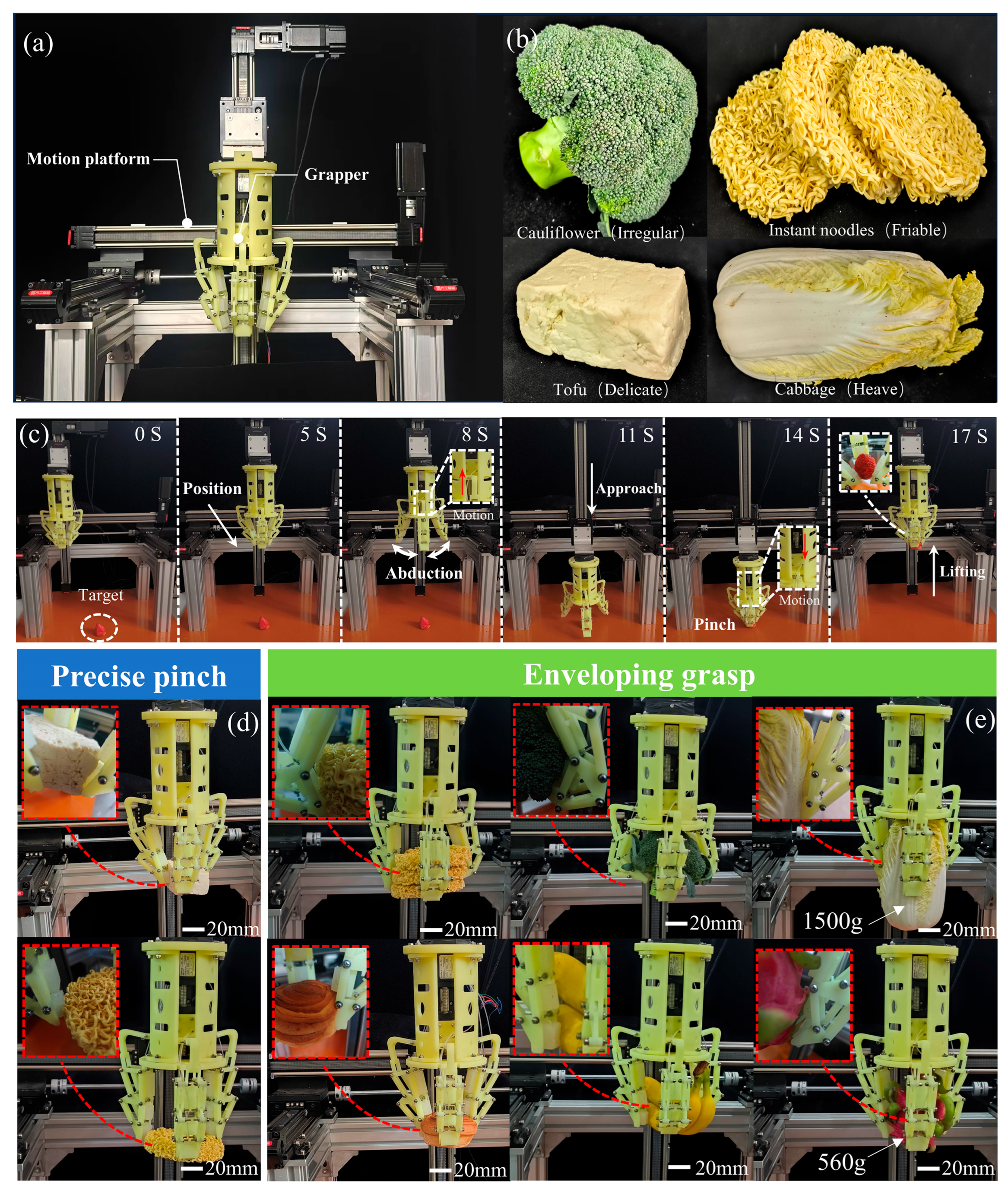
The U-RFCG was successfully integrated into a three-dimensional motion platform to demonstrate its universal grasping performance. As illustrated in
Figure 10a, the drive system of the platform comprises motors and linear guides distributed along the X, Y, and Z axes, enabling precise linear movement of the gripper in all directions and facilitating accurate positioning at designated working locations. This system has demonstrated effectiveness in executing various fruit grasping tasks. As shown in
Figure 10b, the target objects exhibit diverse physical characteristics, including irregularly shaped cauliflower, fragile instant noodles, soft tofu, and heavy cabbage, thereby highlighting the strong adaptive grasping capability of U-RFCG.
For small-sized objects, the gripper employs a pinching mode, utilizing its distal phalanges to securely grasp items. Importantly, the incorporation of flexible materials increases the contact area and distributes localized pressure, minimizing surface damage during the grasping process. Strawberries, representative of small and delicate objects, have a skin thickness ranging from 0.2 to 0.5 mm, rendering them highly susceptible to mechanical injury. Achieving non-destructive grasping of strawberries presents a significant challenge for robotic manipulation. Therefore, precise control of end-effector contact force is essential during the pinching process. As depicted in
Figure 10c, the process of the gripper grasping a strawberry precisely in pinching mode is demonstrated. The motor-controlled three-dimensional motion platform first positions the gripper at the target location. Subsequently, the precision lead screw mechanism within the drive module actuates the three underactuated fingers to open synchronously. Upon descent to the target point via
z-axis motor control, the internal drive module initiates finger closure toward the center until the distal phalanges make contact with the object, completing the pinch grasp—effectively mimicking human fingertip grasping behavior. Notably, post-grasping inspection revealed no damage to the strawberry skin, attributable to the protective function of the flexible air cavity.
To further evaluate performance in pinching mode, more challenging objects were tested. As shown in
Figure 10d, tests were conducted on tofu and extremely fragile fried instant noodles. Unlike strawberries, which possess a protective outer layer, tofu is fully exposed and prone to deformation or fracture during handling; additionally, its relatively high mass necessitates sufficient clamping force for stable grasping. Fried instant noodles, by contrast, are highly sensitive to external pressure. These conditions demand precise modulation of contact forces to prevent damage. Significantly, the U-RFCG successfully lifted both tofu and fried instant noodles from their initial positions to a height of 30 cm and transported them horizontally at this elevation (
Video S1), with no observable damage incurred. These results indicate that the gripper can apply appropriate contact forces in pinching mode, ensuring safe and stable handling of fragile and vulnerable objects.
For large or complex-shaped objects, the gripper operates in enveloping mode. As illustrated in
Figure 10e, enveloping grasping experiments were conducted on objects with varying morphological features. These included a stack of three fried instant noodles—more voluminous and structurally complex than single-layer counterparts—and a surface-crispy bread. In both cases, the U-RFCG achieved successful grasping without causing fragmentation or structural damage. To further assess enveloping capability, we conducted tests on a variety of irregularly shaped fruits and vegetables (
Video S2). Results show that when interacting with clustered cauliflower or elongated bananas, each phalanx made contact with the object surface, and the fingers adaptively conformed to the contours, achieving complete envelopment. Furthermore, to assess the load-bearing capacity of the gripper, which is a critical performance metric, we evaluated the gripper by having it grasp a 1500 g cabbage and a 560 g pitaya (
Video S3). The U-RFCG is able to firmly grasp and smoothly transport both items. Crucially, after completion of the grasping task, the flexible components on the underactuated fingers securely attached to the rigid structure without slippage or delamination, even under substantial load. This demonstrates not only the high load tolerance of the gripper but also the effectiveness of embedded microstructure in robustly coupling materials with significantly different elastic moduli. Moreover, all the grasping actions are driven by a single motor, which indicates that U-RFCG features a simplified control system and a versatile structure.
In summary, the U-RFCG exhibits outstanding performance in both pinching and enveloping modes. The integration of flexible elements effectively protects grasped objects, with no damage observed across all test scenarios. The rigid structure provides excellent adaptability and load-bearing capacity, while the flexible microstructure functions reliably as an interfacial coupling agent, ensuring stable integration between rigid and soft components. These outcomes align closely with the original design objectives.
