Article

Towards Robust Physical Adversarial Attacks on UAV Object Detection: A Multi-Dimensional Feature Optimization Approach

1
Equipment Management and Unmanned Aerial Vehicle Engineering School, Air Force Engineering University, Xi’an 710043, China
2
National Key Laboratory of Unmanned Aerial Vehicle Technology, Xi’an 710043, China
3
The Youth Innovation Team of Shaanxi University, Xi’an 710043, China
4
Air Traffic Control and Navigation School, Air Force Engineering University, Xi’an 710043, China
5
China Academy of Space Technology (Xi’an), Xi’an 710051, China
*
Author to whom correspondence should be addressed.
Machines 2025, 13(11), 1060; https://doi.org/10.3390/machines13111060
Submission received: 5 October 2025 / Revised: 28 October 2025 / Accepted: 14 November 2025 / Published: 17 November 2025
(This article belongs to the Special Issue Intelligent Control Techniques for Unmanned Aerial Vehicles)

Abstract

Deep neural network (DNN)-based object detection has been extensively implemented in Unmanned Aerial Vehicles (UAVs). However, these architectures reveal significant vulnerabilities when faced with adversarial attacks, particularly the physically realizable adversarial patches, which are highly practicable. Existing methods for generating adversarial patches are easily affected by factors such as motion blur and color distortion, leading to a decline in the attack success rate (ASR). To address these limitations, a low-frequency robust adversarial patch (LFRAP) generation framework that integrates three dimensions of color, texture, and frequency domain is proposed. Firstly, a dynamic extraction mechanism for the environmental color pool based on clustering is proposed. This mechanism not only improves the degree of environmental integration but also reduces printing losses. Secondly, mathematical modeling of the effects of Unmanned Aerial Vehicle (UAV) high-speed motion is incorporated into the patch training process. The specialized texture derived from this modeling alleviates patch blurring and the subsequent decrease in attack efficiency caused by the high-speed movement of UAVs. Finally, a frequency domain separation strategy is introduced in the generation process to optimize the frequency space distribution, thereby reducing information loss during image recapture by UAV vision systems. The experimental results show that this framework increased the environment integration rate of the generated patches by 18.9%, and the attack success rate under the condition of motion blur increased by 19.2%, which significantly outperformed conventional methods.

1. Instruction

As exemplars of emerging unmanned systems, unmanned aerial vehicles (UAVs) have achieved substantial enhancements in intelligent operational capabilities in recent years. Specially within the visual domain, UAVs integrated with intelligent object detection systems exhibit augmented information perception and analytical decision-making capacities. This enables their extensive applications in precision agriculture [1], disaster response [2], logistics transportation [3], and information reconnaissance [4]. As noted by Nex et al. [5], current research on UAVs predominantly focuses on the field of remote sensing. This can be attributed to the characteristics of UAVs themselves, such as their high maneuverability and low cost. In recent years, the integration of intelligent object detection technologies has further enhanced their capabilities. UAVs can now better leverage their wide field of view and high mobility to rapidly locate target areas and collect data efficiently. As a result, UAVs have emerged as the most popular tool in low-altitude remote sensing.
Object detection is one of the important functions of UAVs, and it also serves as a crucial basis for UAVs to autonomously complete various complex tasks such as obstacle avoidance and path planning [6]. However, intelligent detection algorithms based on deep neural networks (DNNs) are facing a type of inherent security threats, particularly adversarial attacks [7]. Attackers can evade detection by injecting meticulously crafted perturbations into target images. In the digital domain, adversarial attacks involve generating imperceptible perturbations on collected digital images, thereby inducing erroneous outputs from detection models [8]. Nevertheless, such methods require attackers to access and manipulate input data, which is often impractical in real-world scenarios. Recent research trends have increasingly shifted toward physically realizable adversarial attacks, where attackers deploy printable adversarial patches or other physically implementable means to introduce perturbations directly onto target surfaces or surrounding environments, thereby inducing erroneous outputs from the target model.
Compared to autonomous vehicles, UAVs operate in highly dynamic open environments during image acquisition, making them particularly susceptible to environmental disturbances such as adverse weather conditions and high-speed flight dynamics [9]. Current research on physical adversarial attacks against Unmanned Aerial Vehicle (UAV)-based object detection primarily focuses on optimizing the generation of adversarial patches in the digital domain, while largely neglecting the practical challenges associated with physical deployment. These challenges include printing artifacts, motion-induced blurring, and other environmental interferences, all of which can significantly degrade attack efficacy in real-world scenarios. Figure 1 exemplifies the impact of physical adversarial patches on the UAV object detection task.
This paper proposes a robust adversarial patch generation strategy tailored for UAV-based object detection scenarios. A three-dimensional collaborative optimization framework encompassing the spatial, frequency, and color domains was constructed, which provides a deployable solution for adversarial attacks in dynamic physical environments. This work enhances the ability of existing studies to optimize the environmental adaptability of adversarial patches. The key contributions are as follows:
  • An environmental adaptive color pool extraction method for adversarial patches is designed. The method enables the patch colors to blend better with the surrounding environments.
  • A texture-based method for anti-blur of patches is proposed. By accurately mathematically modeling the blurring effects caused by the high-speed movement of UAVs, a progressive transformation module based on data augmentation is proposed. Specific textures are generated to suppress the motion-blur effect, thereby reducing the loss of adversarial patches during high-speed UAV photography.
  • Frequency domain computation methods are introduced into the adversarial patch generation process. This not only effectively reduces the information loss of adversarial patches after printing and secondary capture, but also improves the patch generation speed.

2. Related Works

2.1. Object Detection on Unmanned Aerial Vehicle

As a core area at the intersection of computer vision and aviation technology, UAV-based object detection has made remarkable progress in both algorithm optimization and application expansion in recent years, propelled by deep learning-related technologies. This has gradually made UAVs the main force in low-altitude information detection.
Among the object detection algorithms currently available for UAVs, two-stage based ones include RCNN (Region-based Convolutional Neural Networks), R-FCN (Region-based Fully Convolutional Networks), etc., and one-stage based ones include YOLO (You Only Look Once), SSD (Single Shot Multi-Box Detector), RetinaNet, etc. Among the numerous intelligent object detection algorithms available for selection, the YOLO series of algorithms, characterized by their lightweight nature, rapid inference speed, and high accuracy, have become the preferred choice for many UAV applications.
Mittal et al. [10] conducted a comprehensive survey and comparative analysis of prevailing object detection algorithms, but their evaluation framework lacked specific environmental considerations for UAV, particularly regarding aerial imaging dynamics and platform mobility constraints. Bouguettaya et al. [11] specifically addressed vehicular detection in UAV-captured aerial imagery, providing a methodological synthesis of enhanced network architectures (e.g., attention mechanisms, multi-scale feature fusion) and their quantitative improvements in precision-recall metrics for moving vehicle identification. Cao et al. [6] presented a systematic review encompassing three critical dimensions: embedded hardware platforms, operational scenarios, and algorithmic parameter optimization, while emphasizing the indispensable role of GPU-accelerated edge computing in achieving real-time processing for UAV-based detection systems.

2.2. Physical Adversarial Attacks for Object Detection

Adversarial attacks have been empirically demonstrated to significantly compromise DNN-based intelligent approaches [12]. Compared to digital adversarial attacks that require stringent implementation prerequisites, physically realizable adversarial attacks have garnered increasing research attention due to their superior feasibility in the real-world. Adversarial attacks can be classified into physical-object-based attacks and projected-energy-based attacks. Physical-object-based attacks: This type of attack interferes with the model by introducing a physical object with specific textures, shapes, and colors, such as adversarial patches or adversarial graffiti. The attack effect depends on the visual appearance of this object in the image. Athalye et al. [13] first proposed the concept of “expectation over transformation” to optimize the generation of a robust adversarial example capable of withstanding these transformations. Sharif et al. [14] developed adversarial eyeglass frames capable of deceiving facial recognition systems through physically realizable attacks. Song et al. [15] demonstrated the first successful extension of physical adversarial attacks from image classification to object detection by deploying monochromatic patches on traffic signs, thereby inducing misclassification in autonomous vehicle perception systems. Subsequently, Maesumi et al. [16] advanced the field by transitioning from two-dimensional to three-dimensional adversarial patches, designing deformable 3D adversarial patterns that maintain effectiveness across varying human postures through kinematic-aware optimization. Subsequently, Guesmi et al. [17] conducted a relatively comprehensive review of the current major physical adversarial attack methods and pointed out several possible future development directions.
Projected-energy-based attacks: On the contrary, this type of attack directly interferes with the imaging process by projecting a certain form of energy, such as laser beams or structured light, into the sensing field of the sensor. The attack effect stems from the direct tampering of the sensor readings or digital signals by the projected energy. Duan et al. [18] proposed an adversarial laser beam attack method by exploiting optical interference during the acquisition process of the object detection system. Jing et al. [19] established a projectable color spectrum and developed a projection model for generating adversarial perturbations, effectively misleading autonomous vehicle perception systems. Correspondingly, Zhong et al. [20] considered the influence of shadows on object detectors, where attackers simulated various shadow occlusion patterns on targets to achieve adversarial attacks. Guesmi et al. [21] designed raindrop-shaped adversarial patterns printed on translucent films for lens occlusion, successfully evading detection systems. Overall, while demonstrating superior stealthiness, these non-contact attack methods generally require specialized equipment, resulting in higher implementation costs and reduced operational convenience compared to contact-based approaches.
While significant advancements have been made in adversarial attacks across various deep learning domains, their application to UAV systems remains at a relatively nascent stage [22]. Early efforts primarily focused on validating attack feasibility in digital domains. For instance, Tian et al. [8] pioneered the first digital-domain verification of adversarial attack effectiveness against UAV-based object detection systems, establishing an important foundational benchmark. Subsequent research has progressively incorporated physical-world constraints to enhance practical applicability. Du et al. [23] developed an adversarial patch generation method specifically tailored for vehicles in aerial imagery, marking a step toward physical deployment. Building on this, Shrestha et al. [7] improved robustness by integrating critical UAV imaging parameters—such as viewing angle, altitude, and environmental illumination—into the patch optimization process. Recently, studies have begun to address the geometric complexities inherent in UAV-based capture environments. Cui et al. [24], for example, advanced the field further by accounting for variations in the projective matrix under 3D aerial imaging conditions. They introduced a projection-transform-based patch generation methodology that better adapted to dynamic UAV viewpoints, thereby significantly improving cross-pose robustness. Despite these developments, current approaches still face challenges in cross-domain generalization and maintaining effectiveness under highly dynamic environmental conditions—limitations that motivate the present study.
While existing studies have incorporated certain environmental factors, the cross-domain deployment—specifically, the transition from digital generation to physical deployment—and environmental adaptability of physical adversarial patches present fundamental challenges. Specifically, the following two aspects of research are insufficient:
  • Insufficient cross-modal distortion modeling during digital-to-physical domain conversion. Traditional approaches rely on Total Variation Loss (TV Loss) and Non-Printability Score (NPS Loss) to constrain patch smoothness and printability. However, TV Loss addresses spatial smoothness but does not explicitly protect against frequency-domain distortions like motion blur. Meanwhile, during the physical deployment stage, there is a lack of a patch generation mechanism that matches the environmental color scheme and control of high-frequency information loss that adapts to the environment, resulting in simultaneous degradation of both the stealthiness and attack success rates in practical applications.
  • Inadequate consideration of secondary feature of physical patches degradation during their dynamic capture by UAVs. Deployed adversarial patches face multimodal interference under high-speed UAV imaging conditions, including environmental factors and motion-induced artifacts. Although some works have attempted to enhance robustness through physical augmentation, they have not yet solved the coupled effects of motion blur and frequency domain shift during capture, leading to spatiotemporal feature degradation of the patches.

3. Methods

In this paper, for the object detection task in UAV aerial images, a low-frequency robust adversarial patch generation (LFRAP) framework for dynamic scenes is proposed. The aim was to generate adversarial patches covering the target surface to enable the target to evade aerial detectors.
Compared with other works, on the premise of ensuring the attack performance of adversarial patches, our aim was to address the dual-loss problem caused by the conversion between digital patches and physical patches, which has not been well-solved in the current research. Specifically, it includes: (1) cross-domain feature mismatch caused by print distortion and color shift of adversarial patches; and (2) motion blur and secondary feature degradation caused by high-speed shooting of UAVs.
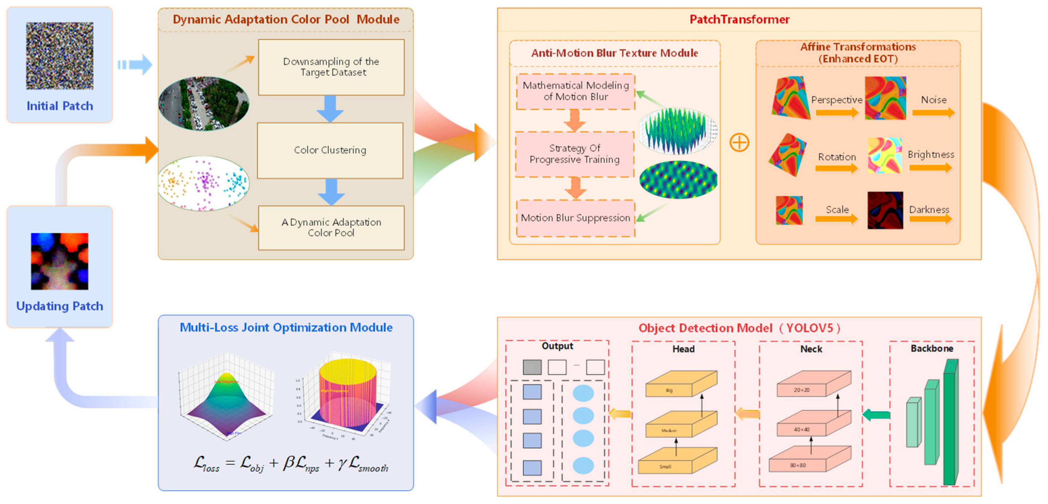
As depicted in Figure 2, we proposed a Low-Frequency Robust Adversarial Patch Generation Framework. Through the collaborative operation of three core modules, this framework sequentially addresses color adaptation, physical transformation simulation, and multi-objective constraint optimization, ultimately generating robust patches that can effectively attack object detectors such as YOLOv5. The detailed process is as follows:
First, the Dynamic Adaptive Color Pool (DACP) module is responsible for extracting representative colors from the object UAV scene. The initial patch undergoes color updating within this color pool, enabling it to blend better with the background visually.
Subsequently, the color initialized patch is fed into the Patch Transformer module to simulate various perturbations in the real physical world. This module consists of two key components:
(a)
Anti Motion Blur Texture (AMBT): This part directly integrates the mathematical modeling of motion blur into the patch training process. By applying simulated motion blur to the patch, the optimization process is compelled to generate textures that are inherently resistant to such blur, thus significantly enhancing the patch’s effectiveness in scenarios where the UAV is moving at high speed.
(b)
Affine Transformation: This part is used to simulate various geometric and photometric changes that the patch may encounter in the real environment, such as multi-angle perspectives, illumination fluctuations, and random noise. By introducing these transformations, the patch can maintain its adversarial nature in complex and variable environments.
Finally, the Multi-Loss Joint Optimization (MLJO) module comprehensively constrains the transformed patch. This module takes the output of the YOLOv5 object detection model as the optimization target and constructs loss functions to constrain the patch training process. The specific meanings of each loss function are described in Section 3.4.

3.1. Construction of Dynamic Adaptation Color Pool

In early studies of physical adversarial attacks, the color optimization for patches received limited attention. Sharif et al. [14] employed a predefined color palette approach, extracting RGB (Red, Green, Blue) values of 100 common colors through the actual printing and scanning of color charts for adversarial patch generation. The method calculated the distance between each pixel in the patch and its nearest neighbor in the color palette, penalizing pixels deviating from printable colors. Thys et al. [25] selected 28 common colors from Pantone cards for patch generation, but this device-dependent color palette construction failed to cover complex scenarios. Komkov and Petiushko. [26] directly optimized digital colors by introducing random perturbations in the HSV (Hue, Saturation, Value) color space, while Du et al. [23] utilized GANs (Generative Adversarial Networks) to generate digital colors combined with physical simulation for patch optimization. However, this approach exhibited high training complexity, required substantial computational resources, and potentially produced physically unrealizable, unnatural colors.
These studies, whether employing predefined color palettes or dynamic generation techniques, inadequately addressed both the printability of patch colors and their environmental compatibility. Therefore, this paper proposes a strategy of color filtering based on dynamic extraction, so that the generated patches are more compatible in terms of the environment.
In order to enhance the color matching degree between the patches and scenarios, this paper proposes an environment-based Dynamic Adaptation Color Pool (DACP). The module establishes a multi-stage processing pipeline to extract printable, environment-specific colors from UAV aerial datasets, generating a standardized color pool of K candidate colors. The module consists of the following parts:
  • Data sampling. To ensure the comprehensiveness of the color distribution obtained through sampling and to control the computational complexity, we employed a two-stage sampling algorithm to extract colors from the target environment for patch generation. Firstly, a random selection of images is made from the input dataset. For each image, random down-sampling is performed. When the single image-pixel quantity after down-sampling is less than 1000, all available pixels are retained. Then, during the second-stage sampling, the overall pixel pool is adjusted to maintain a balanced distribution. Then, all pixels are merged for a second round of random sampling to generate a candidate pixel matrix of magnitude.
  • Color clustering. The K-means algorithm is used to extract the main colors from all the sampled auxiliary colors, in order to obtain the most representative colors in the target environment. The clustering method is presented as the following equation:
    C   =   a r g m i n C k x i X   x i c k 2  
    where c k represents the cluster center and x i is the RGB pixel vector. The clustering process is initialized multiple times to avoid local optima, and the Elkan algorithm [27] is used to optimize the efficiency of distance calculation.
  • Cross-space filtering and screening. Based on the colors obtained from the previous two steps of clustering, we further establish a three-level color filtering criterion to enhance the usability of the colors.
(a) Convert the color palette into HSV space, where low-saturation and oversaturated colors are filtered out while retaining moderately saturated hues:
S c = 1 255   Ψ R G B H S V   c 1 0.2 , 0.8
where S c is the saturation constraint function in the HSV color space, Ψ R G B H S V   c is the method for converting the RGB color space to the HSV color space, and the sequence number 1 indicates that the function Ψ outputs the first component of the three-component weight, which is the saturation. By selecting the element at index 1 , we explicitly isolate the saturation value S(c), which is then normalized by 1 / 255 to constrain it within the range 0.2 ,   0.8 . This step is essential to our dynamic color pooling strategy, as it filters out colors with insufficient or excessive saturation—ensuring that the resulting adversarial patches maintain visual plausibility and environmental adaptability when deployed under real-world UAV imaging conditions.
(b) CMYK (Cyan Magenta Yellow Black) compatibility verification. Utilizing a professional-level color management solution, based on the U.S. Web Uncoated ICC (International Color Consortium) profile, the filtered colors are converted to the CMYK space suitable for the printer, and non-printable colors are eliminated. The specific transformation formulas are as follows:
C M Y K = T I C C · R G B
where T I C C is a 4 × 3 transformation matrix defined by the ICC profile.
(c) Adaptive spacing threshold to prevent the extracted colors from being overly concentrated and to maintain color diversity:
D ( c , C ) = min c C c c 2 0.12   if   | C | > 20 min c C c c 2 0.10   otherwise
where D ( c , C ) represents the color set obtained through adaptive spacing screening, and c denotes a single value selected from the screening process. The final set of color spaces C obtained is:
C = c C init E ( c ) = 0 S ( c ) G ( c ) D ( c , C ) C backup
G ( c ) = 1 if   i { 1 , , 4 } : 0 Y RGB CMYK c i 1 0 otherwise  
where C backup represents the secondary optimal color that is prioritized for supplementation when the effective color is less than the required quantity of the color pool, and it is compatible with CMYK. c is an arbitrary color vector in the set C . The symbol “ ” represents the logical operator “and”. This indicates that a color must satisfy two conditions simultaneously in order to be included in the final color pool C . G ( c ) is the print-feasibility determination function. When G ( c ) = 1 , it indicates that all CMYK components are within the range of [ 0 , 1 ] , and thus the content is printable. When G ( c ) = 0 , it means that at least one component exceeds the range, and the content is not printable. Table 1 summarizes this strategy for color selection across different spaces.

3.2. Design of Anti-Motion Blur Texture

Motion blur arises from relative motion between the camera and objects during image acquisition, resulting in the imaging sensor recording the position changes of the object over a period of time rather than a single instant’s image. Therefore, a series of overlapping shadows along the direction of motion are produced on the image. In UAV-based imaging systems, such blurring effects become difficult to avoid during high-speed flight operations due to platform dynamics and environmental disturbances [29].
Such blurring not only obscures the contours and discriminative features of the target object itself, but also significantly degrades the effectiveness of adversarial patches affixed to the target surface. Since the attack performance of adversarial patches critically depends on their precise color distributions and well-defined texture patterns, motion blur will disrupt the original chromatic precision and structural integrity. This degradation consequently results in a significant decline in the performance of the patches in image processing and recognition algorithms, substantially diminishing their interference capability against object detection systems.
In the field of image processing, motion blur is often modeled as a convolution operation [30], as shown in Equation (7):
I blurred = I original K θ K θ = 1 L δ ( y x tan θ )   x [ L / 2 , L / 2 ] δ ( x ) = 0 ,   x 0   ,   x = 0
where I original is the clean original image, I blurred is the blurred image, δ is the Dirac delta function, and K θ is the convolution kernel defined by the length L and the angle θ .
Wang et al. [31] indicates that specific patterns of texture can still retain key frequency features after motion blur. Inspired by this, we integrated anti-blur texture learning into the Expectation over Transformation (EOT) framework to enhance the robustness of adversarial patches [13]. Typically, EOT is employed during training to simulate geometric transformations such as rotation, scaling, and perspective changes—common in UAV-captured imagery. However, accurately modeling motion blur requires knowledge of the blur direction, which is often unpredictable in real-world UAV applications.
To address this, we continuously generated blurs with random phases during EOT-based training. These blurs were superimposed on the current patch with a small weighting factor and incorporated into standard training steps including transformation, image blending, and loss computation. Since θ and θ + π correspond to the same directional blur, the random phase is uniformly sampled from π ,   π within each training batch. This approach ensures that anti-blur textures undergo subsequent geometric transformations alongside the patch, thereby more accurately mimicking real-world conditions and improving the patch’s robustness under motion blur.
During training, a progressive addition strategy was adopted, as shown in Figure 3. Specifically, in the early stage of training, no texture transformations are applied. This allows the network to focus primarily on learning semantic features that are effective for misleading the detector. As training progresses, transformation T is introduced to enable the patches to acquire anti-blur ability. The learning weight λ ( e ) for the motion-blurred texture is dynamically adjusted across training epochs according to Equation (8), ensuring a smooth transition from semantic learning to robustness enhancement.
P t + 1 = P t + λ ( e ) T λ ( e ) = 0 e E s λ 0 1 e E s E P E s e > E s
where T presents the patch transformation that integrates anti-blur learning and EOT, E s = 0.1 E max represents the starting epoch of adding blurry training, E P = 0.8 E max represents the release epoch. E max is the maximum number of training epochs, and λ 0 represents the maximum constraint strength. This strategy permits the training network to initially explore adversarial patterns freely, and then gradually focuses on adapting to environmental perturbations.
Figure 3 illustrates this progressive training strategy. This strategy optimizes adversarial patches in a phased manner. In the initial training stage ( E p o c h   <   E s ), the network focuses on learning powerful semantic attack features from the base patches, without introducing any transformations at this time. In the middle training stage (   E s <   E p o c h < E P ), the transformation T , which integrates anti-blur learning and affine transformation, begins to be gradually introduced. The constraint strength λ e linearly decays from the maximum value λ 0 , enabling the patches to smoothly adapt to physical perturbations while maintaining their attack capabilities. In the late training stage ( E P < E p o c h ), the transformation intensity reduces to zero, and the network performs final fine-tuning on the already robust patches. This process ensures that the patches first acquire high attack capabilities and then gradually enhance their adaptability to environmental perturbations.

3.3. High-Frequency Separation Strategy Based on Fourier Transform

The printing process itself introduces additional degradation. Imperfections in device precision and paper absorbency cause the loss of fine details and blurring, particularly in high-resolution or complex-textured images. When the printed adversarial patches are captured again by UAVs, this part of the detail will suffer secondary loss. Therefore, when designing the training algorithm, a variation loss function is often adopted to constrain image generation. By reducing the difference between adjacent pixels, the image becomes more globally smooth. However, this method of calculating smoothness pixel by pixel will excessively suppress high-frequency details, especially the image edges and textures with adversarial characteristics.
From a frequency-domain perspective, high-frequency components in images correspond to rapidly varying spatial details—regions exhibiting significant pixel-intensity fluctuations over small neighborhoods. For adversarial patches, the high-frequency component is prone to damage or is lost due to motion blur during the acquisition process of the UAV, thereby weakening the attack effect of the patch. Inspired by the frequency-separation strategy proposed by Yadav et al. [32] for suppressing high-frequency noise, we developed a Fourier-based selective smoothing algorithm. This approach selectively filters high-frequency noise generated during training while preserving the patch’s dominant smooth structures, thereby mitigating information loss from printing and the second photography process. The methodology comprises the following steps:
First, the color channels of the input image I H × W × 3 are decomposed into { C k } k = 1 3 . Then, two-dimensional discrete Fourier transform (DFT) and frequency shift operations are performed on each of the three channels separately:
F C ( u , v ) = x = 0 W 1 y = 0 H 1 I C ( x , y ) e j 2 π u x W + v y H
where W and H denote the width and height of the image, respectively, and I C ( x , y ) represents the intensity value of the pixel at the spatial coordinates ( x , y ) in the color channel C , ( μ , ν ) represents the frequency domain coordinate, and by frequency shifting, the zero-frequency component is moved to the center of the spectrum at frequency F C s h i f t ( u , v ) :
F C s h i f t ( u , v ) = F C ( μ W / 2 , ν H / 2 )
To reduce the oscillations [33] generated by the filter in the spatial domain, a phenomenon observed in the spatial domain as artificial contours or waves near edges, which is primarily induced by the abrupt cutoff of frequency components in an ideal low-pass filter, we adopted an equalization mixing strategy of the ideal low-pass filter and the Gaussian filter to design the filter mask M h y b r i d _ l o w , in order to adapt to more general printing scenarios:
M h y b r i d _ l o w = 0.5 M i d e a l + 0.5 M g a u s s M g a u s s ( u , v ) = e ( u u 0 ) 2 + ( v v 0 ) 2 2 σ 2 M i d e a l ( u , v ) = 1 , if   ( u u 0 ) 2 + ( v v 0 ) 2 r 0 , otherwise
where ( μ 0 , ν 0 ) represents the center of the spectrum, r represents the cutoff frequency, and σ represents the standard deviation of the Gaussian distribution. The low-frequency components of the separated image can be expressed as:
F l o w   =   F s h i f t M h y b r i d _ l o w  
The low-frequency main body I l o w   x , y of the image can be obtained through inverse Fourier transformation, as shown in Equation (13):
I l o w   x , y = 1 W H μ = 0 W 1   v = 0 H 1   F l o w   u , v e j 2 π u x W   + v y H  
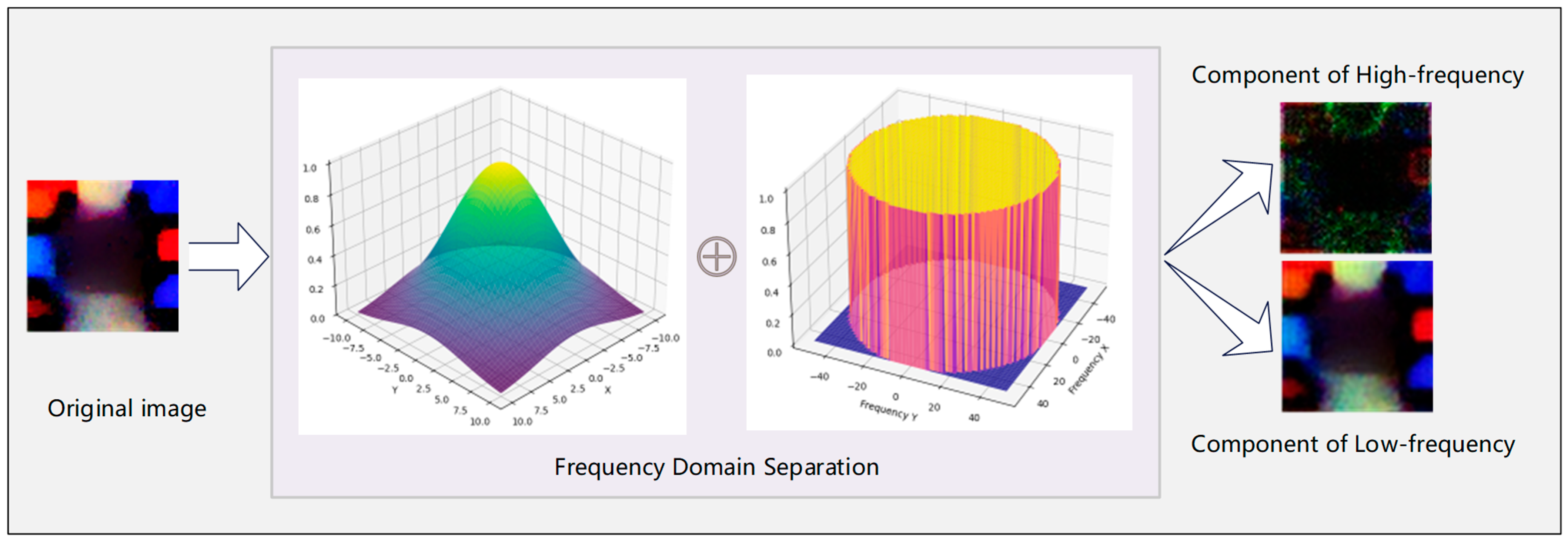
Taking the adversarial patch generated in [9] as an exemplar, we demonstrate the observable effects of this frequency-domain separation strategy in Figure 4.

3.4. Loss Functions

The objective of our training was to obtain an adversarial patch with a high attack success rate (ASR) while maintaining robustness in dynamic environments. To achieve this, we designed an optimization process to update the patch’s pixel values, with loss function constraints divided into three components:
  • Non-printable score loss L n p s :
In conventional methods, the Non-Printable Score (NPS) loss serves to minimize the discrepancy between generated patch colors and printable color. Although Section 3.1 defines a dynamic printable color pool, we retained the NPS loss in training—with reduced weighting in the total loss—to prevent noise artifacts that deviated from the color pool during optimization. The refined NPS loss now primarily functions to maintain color distribution consistency with natural scenes rather than enforcing strict printability.
L n p s = min p d i g i t a l p c o l o r _ p o o l
b.
Smooth loss L s m o o t h :
First, based on Section 3.3, we constructed a frequency loss function L f r e q to filter out the high-frequency components in the patch that are prone to loss.
L f r e q = F s h i f t ( 1 M h y b r i d _ l o w )
Both L f r e q and variation loss functions serve the common objective of enhancing patch smoothness to mitigate information loss during printing and recapture. However, their operation dimensions are different. The variation loss focuses more on smoothing local mutations pixel by pixel, while the frequency loss aims to suppress the global high-frequency information of the patches.
The variation loss using the L1 norm calculates the differences in the horizontal and vertical directions. This may result in a relatively small gradient and a slow convergence speed. On the other hand, the variation loss using the L2 norm can more strongly penalize regions with large differences. Nevertheless, it also has the problem of over-smoothing the edges and weakening the key features of the adversarial texture. Therefore, we redesigned the variation loss function as Equation (16):
L T V m i x = 1 N α i , j | h P i j | 2 + | v P i j | 2 + ( 1 α ) i , j | h P i j | + | v P i j |
where N represents the number of pixels in the patch P , p i , j represents the pixel value at coordinate ( i , j ) of the adversarial patch, h P denotes the horizontal gradient, and v P represents the vertical gradient. α is a hyper-parameter. The final smoothing loss function consists of the above two terms:
L s m o o t h = L T V m i x + L f r e q
c.
Objectness loss L o b j
The objectness loss function serves as the core driving force for training the adversarial patch. Its purpose is to minimize both the classification confidence and the objectness score output by the object detection model. This is conducted to prevent the model from confirming the existence and category of objects, thus enabling a complete evasion of object detection.
L o b j = E i ~ D [ P class ( y | M , x i * ) P obj ( M | x i * ) ]
where E i ~ D represents the expectation over the dataset D , P class ( y | M , x i * ) denotes the conditional probability that the model M assigns to the sample x i * belonging to the category y , and P obj ( M | x i * ) represents the conditional probability that the model M assigns to the existence of the object in the sample x i * . Finally, during the process of training, we adopted the following weighted loss function:
L l o s s = L o b j + β L n p s + γ L s m o o t h
Two hyperparameters β and γ , were employed to scale the respective loss function. The total loss function L l o s s was optimized via the Adam algorithm. During training, the weights and biases of the detection model were kept frozen. Only the pixel values of the adversarial patch were iteratively altered. The objective was to deceive the detection model by causing targets superimposed with the patch.

4. Experiments & Results

In this section, we conducted comprehensive experiments on the LFRAP framework proposed in this paper. Section 4.1 describes the specific experimental settings, and Section 4.2 analyzes the experimental results.

4.1. Experimental Settings

Target Model: Given the limited computing power of the UAV, we selected YOLOv5—a lightweight model—as our target for aerial object detection attacks. The attacker can construct an optimization algorithm based on the parameters of the known model to generate a digital patch and print it out. Considering that the adversarial patch covering the surface of the target should maintain a small size as much as possible, in the experiment, the maximum patch size was set to be a 1/3 of the width of the object anchor box.
Dataset: The experiment employed the classic UAV aerial dataset, VisDrone, to train the weights of the detection model and the adversarial patches [34]. This dataset was collected by UAV cameras under diverse environmental conditions and contains a total of 10,209 static images, covering 12 specific categories. It is primarily used for computer vision tasks such as object detection and target tracking. Given the small size of pedestrians under the overhead perspective of UAVs, we selected four types of objects with better visualization effects: car, truck, van, and bus, as the attack targets. In this experiment, the VisDrone-2019 dataset was adopted. According to the official division of this dataset, the training set it provided (containing 6471 images) was used for model training, the validation set (548 images) was used for hyperparameter tuning, and the test set-Dev (1580 images) was used for the final performance evaluation.
Experimental Metrics: The ASR was used to describe the attack efficacy of the adversarial patches. Specifically, when calculating the ASR, the non-targeted attack strategy was adopted. All misclassifications and non-detections of targets were all regarded as successful attacks. The Attack Success Rate (ASR) is defined as:
A S R = 1 T P N
where T P represents the number of correctly detected targets, and N represents the total number of correctly labeled objects in the dataset when not under attack. When the confidence level drops below 0.5, the attack is considered successful.
Parameters: Referring to the settings of Lian et al. [22], β and γ were set to 0.01 and 2.5, respectively, in Equation (19). The maximum training epochs were set to 300, and the Intersection over Union (IOU) and the objective confidence threshold were set to 0.5 and 0.4, respectively. The experiments were run on an NVIDIA RTX3080Ti GPU under the PyTorch 2.1.0 framework.

4.2. Results and Evaluation

4.2.1. Effectiveness of the Dynamic Color Pool Construction

We compared the effects of the dynamic adaptation color pool (DACP) and the random color pool through two indicators: the Structural Similarity Index (SSIM) and the degree of dispersion in the color space. SSIM is an index for measuring the similarity between two images [35]. Although SSIM is not a direct color-space measurement tool, its calculation is directly based on the pixel values of an image. In the context of this study, the color similarity of an image is directly reflected in the consistency of the local statistical distributions (such as mean, variance, and covariance) of pixel values between the superimposed area and the original background area. This exactly corresponds to the luminance (local mean), contrast (local standard deviation), and structure (local covariance) information that SSIM focuses on. Additionally, in this experiment, pixel-value normalization was performed on all image data, eliminating the interference of absolute luminance differences. This enables the SSIM score to more purely reflect the internal structural similarity composed of color and texture. The value range of SSIM is [−1, 1]. The larger the value, the higher the similarity between the two images, and 1 indicates that the two images are identical. The brief calculation method of SSIM is shown in Equation (20):
S S I M ( x , y ) = ( 2 μ x μ y + C 1 ) ( 2 σ x y + C 2 ) ( μ x 2 + μ y 2 + C 1 ) ( σ x 2 + σ y 2 + C 2 )
where x and y are the brightness values of the original image and the processed image, respectively, μ x and μ y are the means of the two images, σ x 2 and σ y 2 are the variances, σ x y is the covariance, and C 1 and C 2 are small constants for stabilizing the variances.
We placed the patches generated by the DACP and the random color pool onto the images in the VisDrone dataset, respectively, and then compared these patched images with the original ones. The samples for SSIM comparison were exclusively drawn from the test set of the VisDrone dataset. The effectiveness of the DACP was determined by calculating the SSIM values before and after patching. Four groups of data, composed of 50, 100, 150, and 200 randomly selected images, respectively, were used for the comparison.
As can be seen from Table 2, when the patches were superimposed onto clean images, the SSIM values of the patches using DACP were superior to those of the patches using the random color pool. Moreover, an increase in the improvement extent was observed as the sample size was enlarged. Taking the last set of data as an example, the environmental integration rate of LFRAP increased by 12.4%. This indicates that the dynamic color adaptation mechanism proposed in this paper has a better compatibility with the target environment in large-scale dynamic scenarios. After conducting trend verification for the different-sized subsets above-mentioned, we further conducted an evaluation on a total of 1580 images in the test set. Eventually, it was confirmed that DCPAM achieved an average 18.4% improvement in SSIM compared to the random color pool.
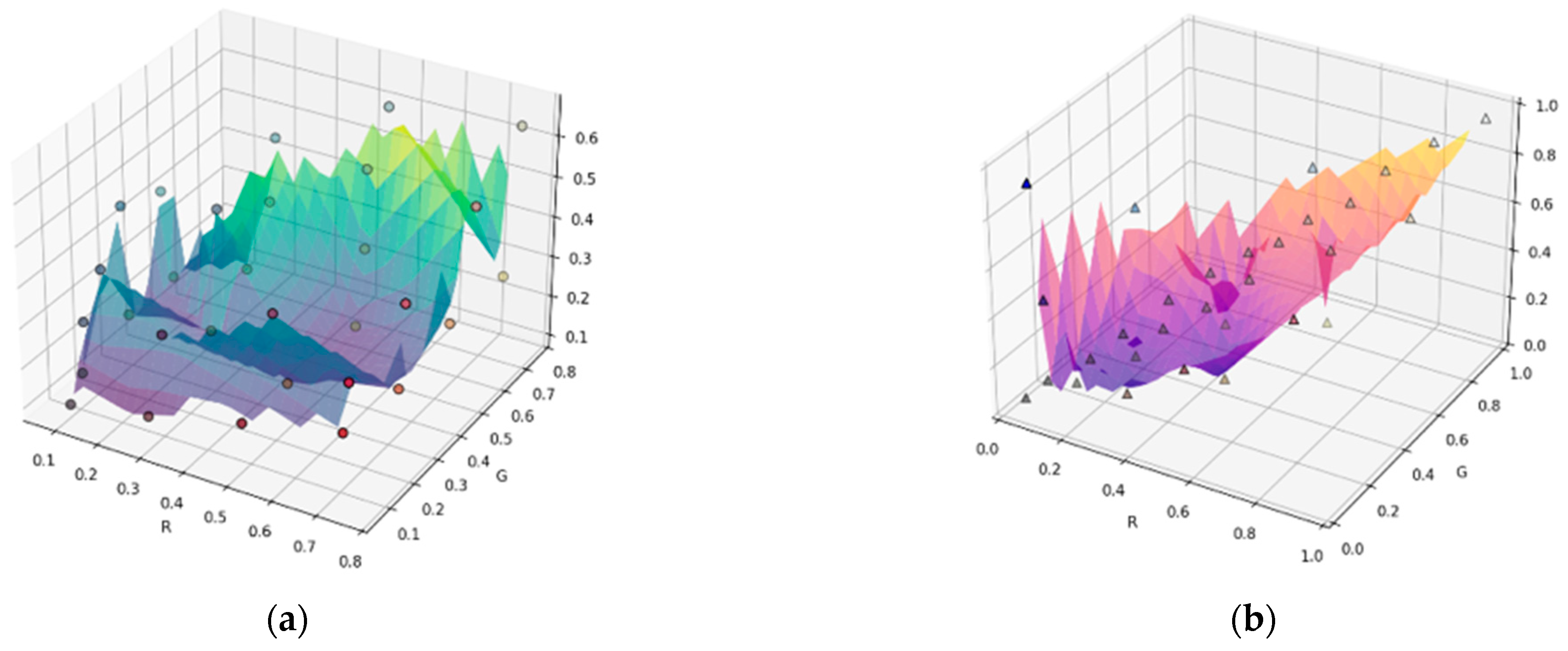
Simultaneously, as can be seen from Figure 5, the color distribution in the random color pool was more extensive, with significant variations in saturation, resulting in distinct differences among colors. In contrast, DACP had better continuity and aggregation, with colors concentrated relatively near several colors that matched the target environment. This color space with less variation from the environment is more conducive to enhancing the integration of the adversarial patch with the environment.

4.2.2. Verification for the Effectiveness of the Adversarial Patches

To validate the effectiveness of the generated adversarial patches, we designed three experiments:
(a)
Compare the attack impacts of random patches and the generated adversarial patches. This was to demonstrate the effectiveness of the adversarial patches.
(b)
Conduct ablation experiments on the two strategies proposed in Section 3.2 and Section 3.3.
(c)
Examine the information loss disparity between anti-blur patches and ordinary patches when both are subjected to the same blur interference.
(d)
Evaluate the ASR of anti-blur patches and ordinary patches after they are affixed to the target surface and subsequently influenced by blur interference.
Among them, the random patch refers to a patch generated by randomly filling colors, and the ordinary patch refers to an adversarial patch without adopting the strategies in Section 3.2 and Section 3.3. For these experiments, 200 images with clear detection effects were selected as the test set, that is, the Average Precision (AP) of the test dataset was 100%. All kinds of patches generated in the experiments had the same size.
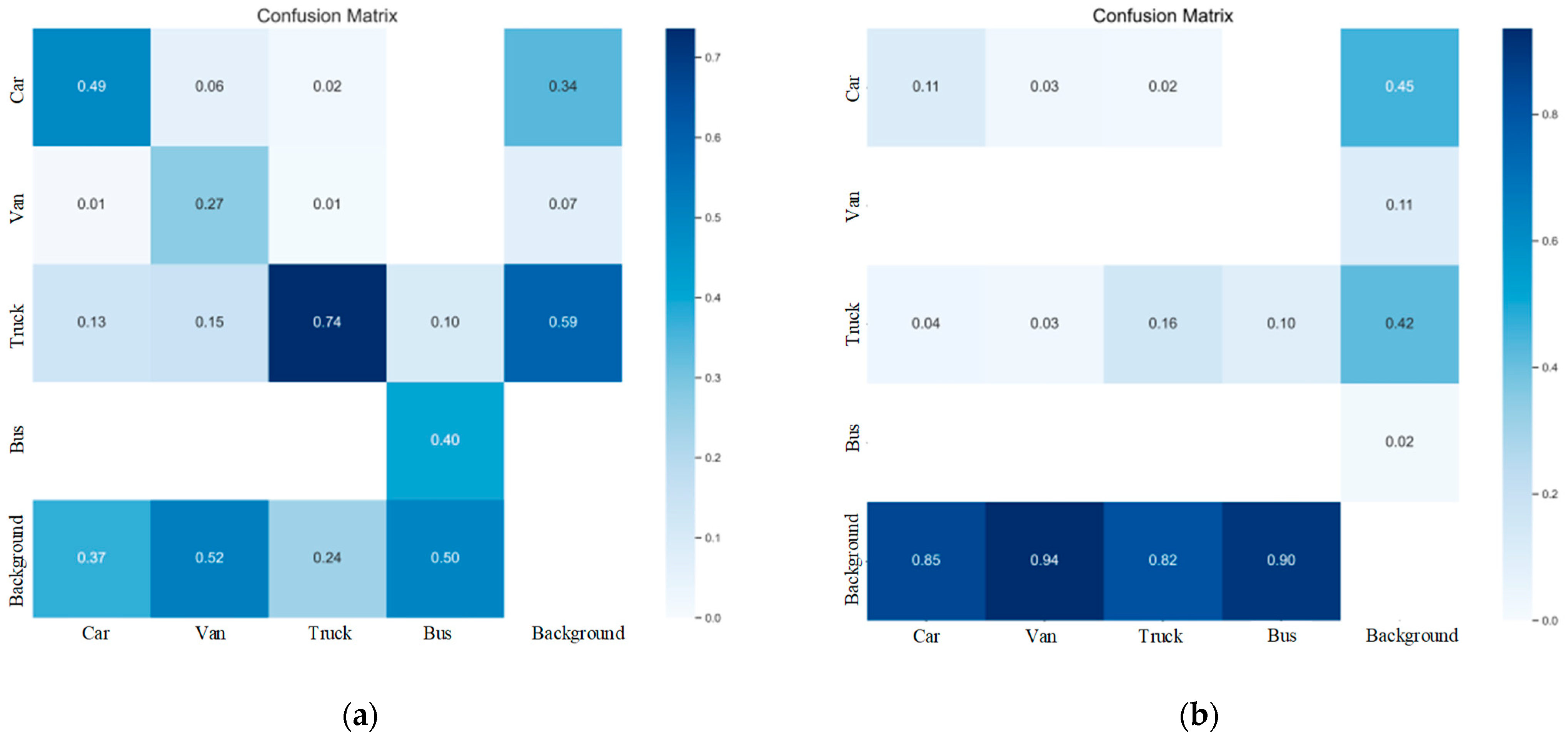
Figure 6 shows the detection results of the YOLOv5 model when two patches of the same size were applied to the target image. We observed that in the random patch attack, although the proportion of four types of vehicles misclassified as the background had increased, the interference effect was limited. For example, the accurate recognition rate of the “truck” category remained at 0.74. In contrast, for LFRAP, the attack energy was precisely directed to the decision boundary of the target vehicle. For instance, the proportions of “van” and “bus” misclassified as “background” increased to 0.94 and 0.90, respectively, an increase of 80.76% and 80% compared to the random patch. Meanwhile, the semantic boundaries of non-target categories remained intact, and the probability of “car” being misclassified as “bus” or “van” was less than 1%. This indicates that the LFRAP is an effective attack method rather than the result of random occlusion of the target.
Figure 7 illustrates the morphologies of adversarial patches generated via different strategies. To further verify the anti-blur interference capabilities of the patches, ablation experiments were conducted under identical interference conditions, specifically where the length of the blur kernel L was 5 and the blur angle was 30°.
As can be seen from Table 3, after being subjected to blur interference, the average ASR of the Normal Patch was merely 45.5%. Its performance on targets of different sizes was all below 47.1%, revealing its sensitivity to motion blur. After adding the Anti-Motion Blur module alone, the average ASR increased to 58.3%, especially showing a significant improvement in small scale targets. After introducing the frequency separation module alone, although the average ASR was similar to that after introducing the Anti-Motion Blur module, the improvement effect on large-sized targets was relatively better. The average ASR of the full version LFRAP increased to 64.7%, representing a relative increase of 19.2%. Its ASR remained at the highest level across all target sizes, suggesting that the two modules contribute independently and synergistically to the core anti-interference ability. The Anti-Motion Blur module mainly enhances the robustness of small-sized targets, while the frequency separation module focuses on optimizing the adaptability of large-sized targets. Together, they form the cornerstone of LFRAP’s high AST in degraded visual environments. However, in the real-world, one of the core goals of the LFRAP framework is to generate patches that are highly robust against motion blur, rather than merely striving for the highest aggressiveness under ideal conditions. Therefore, various complex factors may also cause slight fluctuations in ASR performance. For instance, the ASR of large-sized targets (64.8%) was slightly lower than that of the small-sized targets (65.2%).
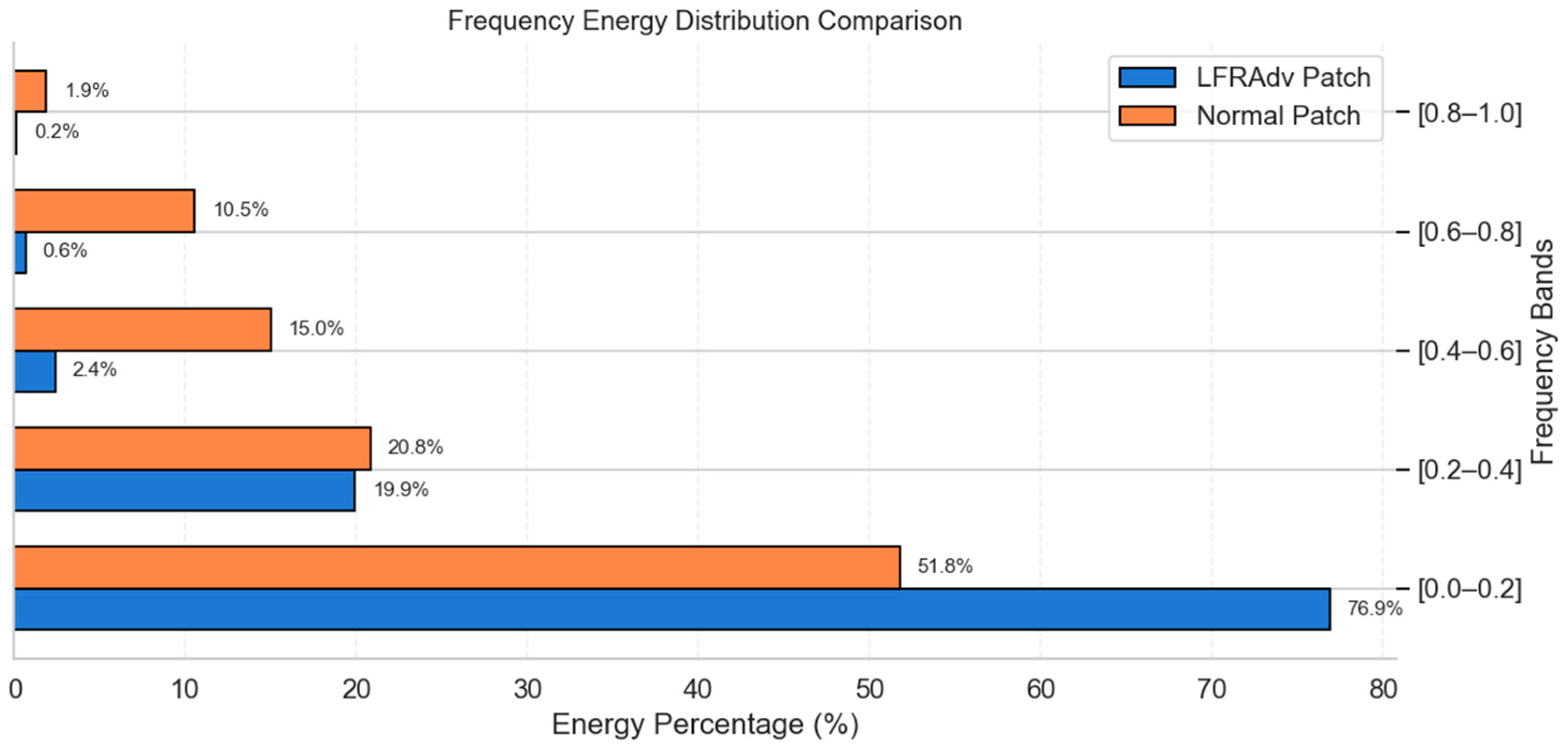
To observe the frequency characteristics of the patches more intuitively, based on Equations (9) and (10), the frequencies of the patches were normalized to the range of [0, 1] and divided into five intervals.
As is evident from Figure 8, irrespective of the method employed, the patches obtained predominantly consisted of low-frequency components. In the low-frequency interval of [0, 0.2], the proportion of the LFRAP was 76.9%, whereas that of the traditional patch was 51.8%. The LFRAP thus had a 25.1% higher proportion in this interval. In the high-frequency interval of [0.6, 1], the proportion of the LFRAP was 0.8%, which was 11.6% lower than that of the traditional patch. This indicates that the LFRAP contains more low-frequency components and demonstrates that the high-frequency separation strategy proposed in Section 3.3 has been highly effective. We further compared the frequency changes of the two types of patches when subjected to the same motion-blur interference, the length of the blur kernel L was 5, and the direction angle was 30°, as depicted in Figure 9.
Through the comparative analysis of the frequency energy distribution in Figure 9, LFRAP demonstrated a significant robust advantage when dealing with motion-blur interference. In the core low-frequency region [0.0–0.2], the fluctuation of the energy proportion of LFRAP before and after blurring was only 1.4%, which was much lower than the 11.7% fluctuation of ordinary patches. In the mid-frequency region [0.2–0.6], the key attack energy of LFRAP decreased by 3.9%, while that of ordinary patches decreased by 6.8%, confirming the resilience advantage of LFRAP in the core attack frequency band. In the highest-frequency interval [0.8–1.0], LFRAP stably controlled the noise energy at 0.2%, which was lower than the 0.7% obtained by ordinary patches. As shown in Figure 9b, the mid- and high-frequency information contained in the original LFRAdv patch, which may be crucial for the attack (for example, the 19.9% energy in the [0.2–0.4] frequency band), was significantly weakened after blurring (decreasing to 12.6%). In contrast, the energy was concentrated in the low-frequency region ([0.0–0.2]). Since low-frequency components are insensitive to smoothing operations such as motion blur, the difference in the energy proportion in the lowest frequency band between the two was extremely small (76.9% vs. 78.3%). This extremely high-frequency component will basically be completely lost when the adversarial patch is photographed by a UAV. Therefore, through the triple mechanisms of low-frequency anchoring, mid-frequency resilience, and high-frequency noise suppression, LFRAP provides a more reliable adversarial attack solution for dynamic scenarios such as UAV-based object detection.
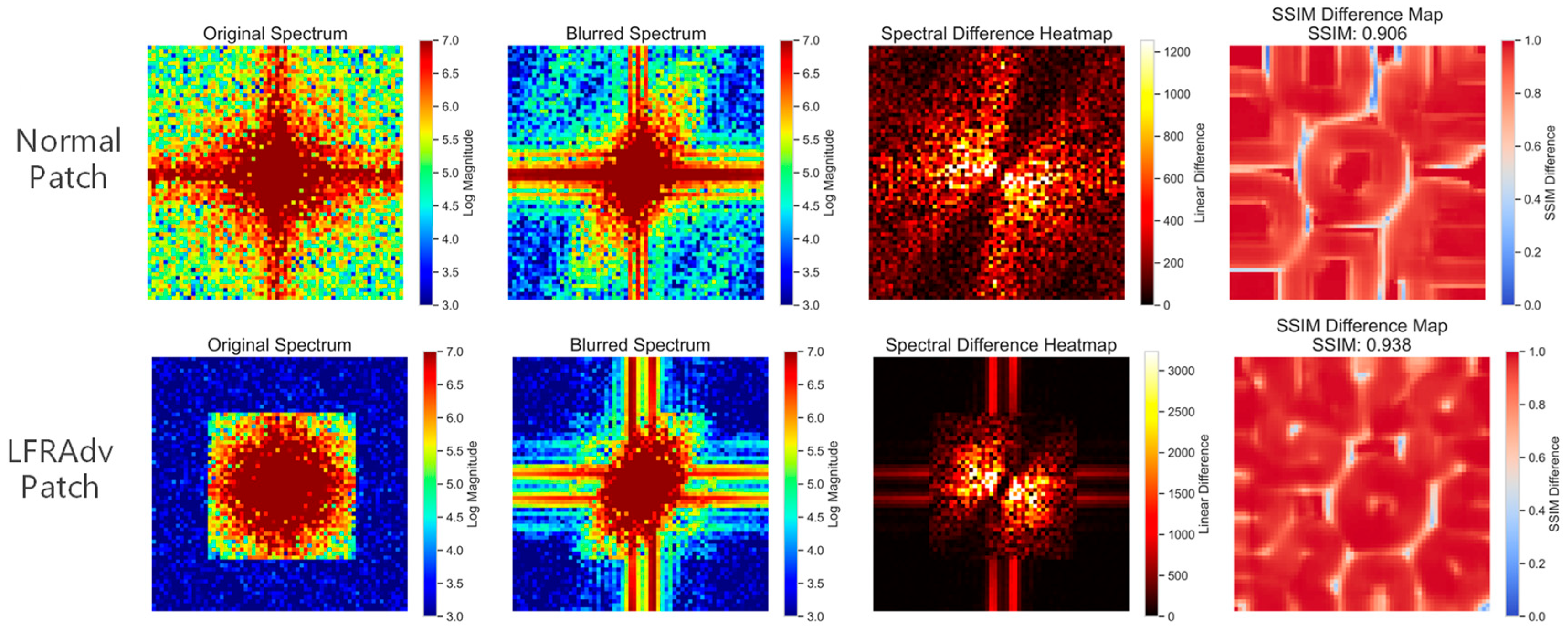
As shown in Figure 10, we further analyzed the interference effects of motion blur on the two types of patches from the perspectives of spectral heatmaps and SSIM value differences. In the spectral difference heatmap, the darker the color, the greater the difference after blurring. In the SSIM difference heatmap, the white areas indicate the parts with significant changes.
For the Normal Patch, after motion blur, the central energy severely attenuated to the yellow band, and a 30° oblique stripe drift formed in the high-frequency region. In the spectral difference heatmap, a large area of bright red regions appeared, and the area with a difference value exceeding 1000 was significantly larger than that in the LFRAP group. In contrast, after blurring, the LFRAP only slightly fluctuated to the yellow area. Most of the area in the heatmap was dark black, and only sporadic orange spots existed at the edge of the high-frequency region. The SSIM value of the LFRAP after blurring was 0.938, which was better than that of the ordinary patch (0.906). Overall, for the ordinary patch, after adding motion interference, the energy showed obvious directional attenuation, and the attenuation was widespread, resulting in a large affected area. Under the same interference conditions, although there were very few high-frequency noise points in the LFRAP, the directionality of information attenuation was significantly weakened, and the affected area was remarkably reduced.
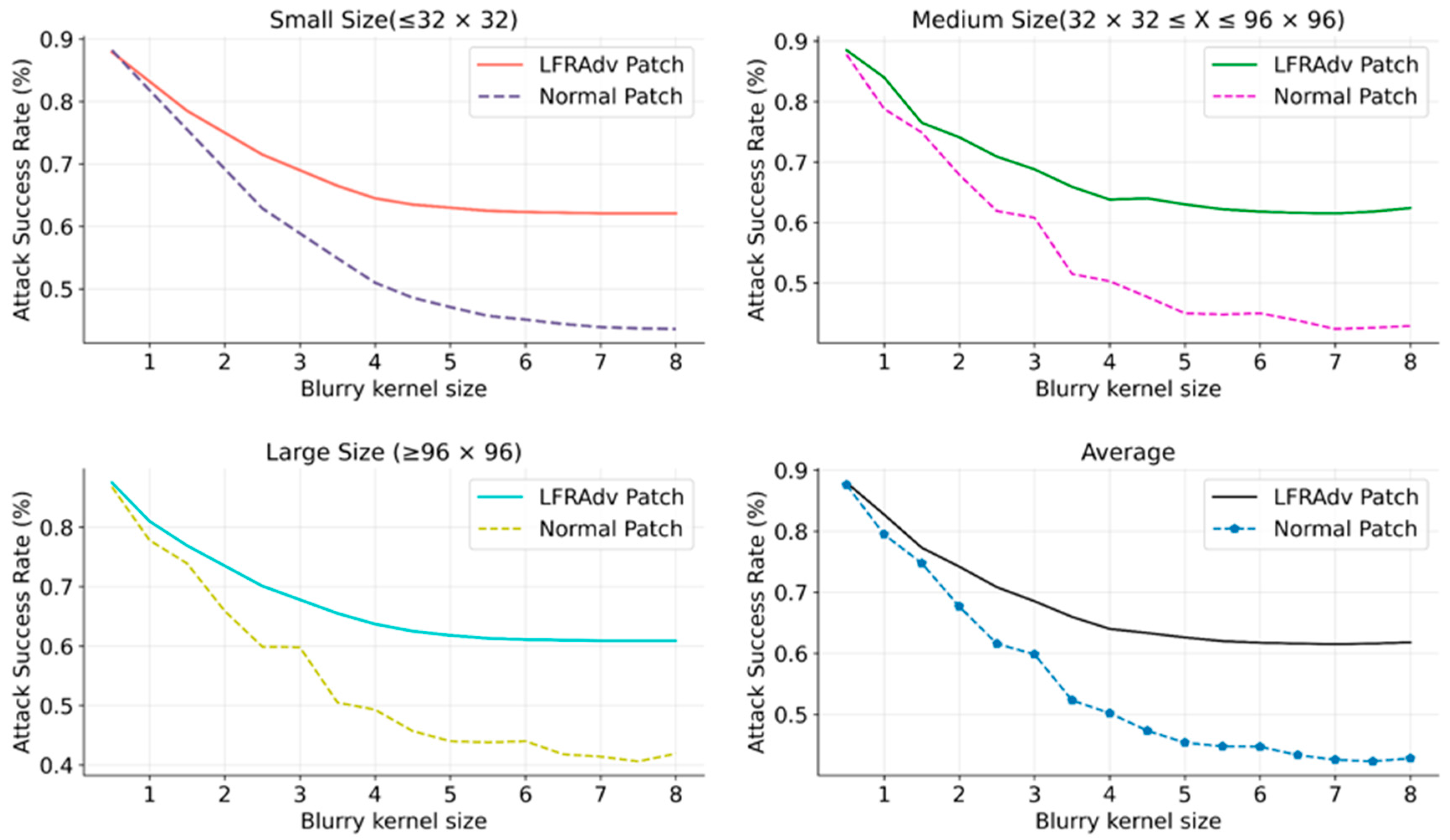
Considering that the sizes of each type of vehicle were not completely identical, we reclassified the vehicles in the target images into three categories according to the size of the detection boxes: Small (≤32 × 32), Medium (32 × 32 ≤ X ≤ 96 × 96), and Large (≥96 × 96). When different values are taken for the blur kernel in Equation (7), the ASR of the two adversarial patches are shown in Figure 11.
For small targets, when the size of the blur kernel increased to 8, LFRAP maintained an ASR of 62.1%, which was 18.5% higher than that of the normal patch. Similarly, for medium and large targets, the ASR of LFRAP was significantly better than that of the normal patch. In terms of the average ASR, as the blur kernel size increased from 1 to 8, the success rate of the normal patch dropped rapidly from 87.6% to 42.3%, a decrease of 45.3%. In contrast, that of LFRAP only dropped slowly from 87.9% to 61.8%, a decrease of 26.1%. That is, the robust mechanism of LFRAP controls the performance degradation caused by motion blur within a relatively small range. This dual advantage of high performance and high stability indicates that LFRAP effectively addresses the problem of adversarial patch feature degradation in a motion blur environment.
To systematically evaluate the generalization ability of the LFRAP framework proposed in this study, we directly applied the generated adversarial patches to other models within the YOLO series that differ in complexity and architecture for testing. The comparative experiments were conducted on the VisDrone test set. Different degrees of motion blur were simulated by fixing the orientation angle of the blur kernel ( θ = 45 ° ) and varying the length of the blur kernel L .
As can be seen from Table 4, under the ideal condition of no blur L = 0 , LFRAP achieved a high ASR (all above 84%) on the four models. This demonstrates that the attack features carried by the adversarial patches it generates are highly universal and can effectively deceive detectors with different architectures and complexities. It is worth noting that the patches achieved the highest ASR (89.2%) on the lightest weight YOLOv5s, which is in line with the common understanding in adversarial attacks that relatively simple models are more sensitive. As the intensity of motion blur increases, the ASR on all models showed an expected decline. However, the downward trend of ASR was relatively gentle among different models. As shown in the right most column of Table 4, the decline rate of all models was controlled within 20%. This indicates that the anti-blur characteristics of LFRAP have good transferability in the physical world.

5. Discussion

5.1. Summary of Key Results

This study proposed a Low-Frequency Robust Adversarial Patch Generation Framework for dynamic UAV scenarios. Experimental results indicate that this framework effectively addresses the key challenges faced by adversarial patches in physical deployments through the collaborative optimization of color distribution, anti-blur texture, and frequency distribution. The core findings confirm that integrating frequency constraints with the desired training framework of physical transformations can significantly enhance the ASR of adversarial patches under interferences such as motion blur and digital to physical domain conversion. This also demonstrates that, in addition to pixel level spatial optimization during the generation of adversarial patches, feature anchoring in the frequency dimension is a highly effective approach.

5.2. Comparison with Existing Works

To more clearly position the contributions of this work, Table 5 presents a multi-dimensional comparison between the LFRAP framework and existing representative physical adversarial attack methods.
Compared with the work of Thys et al. [25], our method abandons the fixed color palette and instead dynamically extracts colors from the target environment. This not only enhances the patch’s concealment, but also improves its applicability in different scenarios. In contrast to the work of Du et al. [23], which focuses on aerial images but does not consider motion blur, our method explicitly integrates the mathematical modeling of motion blur into the training process through the AMBT module, directly addressing the core challenges posed by the high-speed flight of UAVs. Although URAdv [9] has improved robustness through extended physical augmentation, our work is the first to introduce the frequency separation strategy. This strategy actively guides adversarial energy to the low frequency band, thus fundamentally alleviating the problem of high frequency information loss during printing and rephotographing. This optimization in the frequency complements the simple spatial enhancement, constituting a unique advantage of our method.

6. Conclusions

As one of the most prevalent low-altitude reconnaissance platforms, UAVs have been widely deployed across diverse scenarios. This study addresses the information degradation problem during digital-physical bidirectional conversion of adversarial patches in UAV-based object detection tasks, proposing a physically robust generation framework incorporating fused color, texture, and frequency features. It was verified that LFRAP exhibited better robustness against interference factors. Our work provides insights for the evaluation of anti-detection systems and the practical vulnerability assessment of UAV security by enhancing the environmental adaptability of physical adversarial attacks. In the future, researching attack methods against patch detectors will be a feasible direction. Meanwhile, this framework can be further extended to multi-modal sensors such as infrared and SAR radars, and a real-time adaptive mechanism based on reinforcement learning can be developed, which is gradually being translated into practical applications.

Author Contributions

Conceptualization, H.X. and L.R.; methodology, H.X.; validation, R.Z. and W.W.; formal analysis, H.X. and J.T.; investigation, L.L. and S.L.; resources, H.X.; data curation, H.X.; writing—original draft preparation, H.X.; writing—review and editing, H.X. and Z.Z.; visualization, H.X.; supervision, X.L.; project administration, L.R.; funding acquisition, J.T. All authors have read and agreed to the published version of the manuscript.

Funding

This research was funded by the Youth Elite Scientist Sponsorship Program by China Association for Science and Technology under Grant 2024-JCJQ-QT-010, National Natural Science Foundation of China under Grant 62402520, China Postdoctoral Science Foundation under Grant Number 2024M752586, Young Talent Fund of Association for Science and Technology in Shaanxi under Grant 20240105, Shaanxi Provincial Natural Science Foundation under Grant 2024JC-YBQN-0620 and Shaanxi Province Postdoctoral Research Funding Project under Grant 2023BSHYDZZ20.

Data Availability Statement

The download link for the VisDrone dataset is: https://aistudio.baidu.com/datasetdetail/115729 (accessed on 13 November 2025). The data presented in this study are available on request from the corresponding author. The data are not publicly available due to patent pending.

Conflicts of Interest

The authors declare no conflicts of interest.

Abbreviations

The following abbreviations are used in this manuscript:
DNNsDeep Neural Networks
UAVsUnmanned Aerial Vehicles
ASRAttack Success Rate
LFRAPLow-Frequency Robust Adversarial Patch
YOLOYou Only Look Once
DACPDynamic Adaptation Color Pool
AMBTAnti-Motion Blur Texture
MLJOMulti-Loss Joint Optimization
CMYKCyan Magenta Yellow Black
EOTExpectation Over Transformation
NPSNon-Printable Score
IOUIntersection over Union
SSIMStructural Similarity Index

References

  1. Yang, X.; Smith, A.M.; Bourchier, R.S.; Hodge, K.; Ostrander, D.; Houston, B. Mapping Flowering Leafy Spurge Infestations in a Heterogeneous Landscape Using Unmanned Aerial Vehicle Red-Green-Blue Images and a Hybrid Classification Method. Int. J. Remote Sens. 2021, 42, 8930–8951. [Google Scholar] [CrossRef]
  2. Alsamhi, S.H.; Shvetsov, A.V.; Kumar, S.; Shvetsova, S.V.; Alhartomi, M.A.; Hawbani, A.; Rajput, N.S.; Srivastava, S.; Saif, A.; Nyangaresi, V.O. UAV Computing-Assisted Search and Rescue Mission Framework for Disaster and Harsh Environment Mitigation. Drones 2022, 6, 154. [Google Scholar] [CrossRef]
  3. Feng, J.; Yi, C. Lightweight Detection Network for Arbitrary-Oriented Vehicles in UAV Imagery via Global Attentive Relation and Multi-Path Fusion. Drones 2022, 6, 108. [Google Scholar] [CrossRef]
  4. Jun, M.; Lilian, Z.; Xiaofeng, H.; Hao, Q.; Xiaoping, H. A 2dgeoreferenced Map Aided Visual-Inertial System for Precise Uav Localization. In Proceedings of the 2022 IEEE/RSJ International Conference on Intelligent Robots and Systems (IROS), Kyoto, Japan, 23–27 October 2022; pp. 4455–4462. [Google Scholar]
  5. Nex, F.; Armenakis, C.; Cramer, M.; Cucci, D.A.; Gerke, M.; Honkavaara, E.; Kukko, A.; Persello, C.; Skaloud, J. UAV in the Advent of the Twenties: Where We Stand and What Is Next. ISPRS J. Photogramm. Remote Sens. 2022, 184, 215–242. [Google Scholar] [CrossRef]
  6. Cao, Z.; Kooistra, L.; Wang, W.; Guo, L.; Valente, J. Real-Time Object Detection Based on Uav Remote Sensing: A Systematic Literature Review. Drones 2023, 7, 620. [Google Scholar] [CrossRef]
  7. Shrestha, S.; Pathak, S.; Viegas, K. Towards a Robust Adversarial Patch Attack against Unmanned Aerial Vehicles Object Detection. In Proceedings of the IEEE/RSJ International Conference on Intelligent Robots and Systems (IROS), Detroit, MI, USA, 1–5 October 2023; pp. 3256–3263. [Google Scholar]
  8. Tian, J.; Wang, B.; Guo, R.; Wang, Z.; Cao, K.; Wang, X. Adversarial Attacks and Defenses for Deep-Learning-Based Unmanned Aerial Vehicles. IEEE Internet Things J. 2022, 9, 22399–22409. [Google Scholar] [CrossRef]
  9. Xi, H.; Ru, L.; Tian, J.; Lu, B.; Hu, S.; Wang, W.; Luan, X. URAdv: A Novel Framework for Generating Ultra-Robust Adversarial Patches against UAV Object Detection. Mathematics 2025, 13, 591. [Google Scholar] [CrossRef]
  10. Mittal, P.; Singh, R.; Sharma, A. Deep Learning-Based Object Detection in Low-Altitude UAV Datasets: A Survey. Image Vis. Comput. 2020, 104, 104046. [Google Scholar] [CrossRef]
  11. Bouguettaya, A.; Zarzour, H.; Kechida, A.; Taberkit, A.M. Vehicle Detection From UAV Imagery With Deep Learning: A Review. IEEE Trans. Neural Netw. Learn. Syst. 2022, 33, 6047–6067. [Google Scholar] [CrossRef]
  12. Mei, S.; Chen, X.; Zhang, Y.; Li, J.; Plaza, A. Accelerating Convolutional Neural Network-Based Hyperspectral Image Classification by Step Activation Quantization. IEEE Trans. Geosci. Remote Sens. 2021, 60, 550212. [Google Scholar] [CrossRef]
  13. Athalye, A.; Engstrom, L.; Ilyas, A.; Kwok, K. Synthesizing Robust Adversarial Examples. In Proceedings of the International Conference on Machine Learning, PMLR, Stockholm, Sweden, 10–15 July 2018; pp. 284–293. [Google Scholar]
  14. Sharif, M.; Bhagavatula, S.; Bauer, L. Accessorize to a Crime: Realand Stealthy Attacks on State-Ofhe Art Face Recognition. In Proceedings of the 2016 ACM SIGSAC Conference on Computer and Communications Security, Vienna, Austria, 24–28 October 2016; ACM Press: New York, NY, USA, 2016. [Google Scholar]
  15. Song, D.; Eykholt, K.; Evtimov, I.; Fernandes, E.; Li, B.; Rahmati, A.; Tramer, F.; Prakash, A.; Kohno, T. Physical Adversarial Examples for Object Detectors. In Proceedings of the 12th USENIX Workshop on Offensive Technologies (WOOT 18) 2018, Baltimore, MD, USA, 13–14 August 2018. [Google Scholar]
  16. Maesumi, A.; Zhu, M.; Wang, Y.; Chen, T.; Wang, Z.; Bajaj, C. Learning Transferable 3D Adversarial Cloaks for Deep Trained Detectors 2021. arXiv 2021, arXiv:2104.11101. [Google Scholar]
  17. Guesmi, A.; Hanif, M.A.; Ouni, B.; Shafique, M. Physical Adversarial Attacks for Camera-Based Smart Systems: Current Trends, Categorization, Applications, Research Challenges, and Future Outlook. IEEE Access 2023, 11, 109617–109668. [Google Scholar] [CrossRef]
  18. Duan, R.; Mao, X.; Qin, A.K.; Chen, Y.; Ye, S.; He, Y.; Yang, Y. Adversarial Laser Beam: Effective Physical-World Attack to Dnns in a Blink. In Proceedings of the IEEE/CVF Conference on Computer Vision and Pattern Recognition, Denver, CO, USA, 3–7 June 2021; pp. 16062–16071. [Google Scholar]
  19. Jing, P.; Tang, Q.; Du, Y.; Xue, L.; Luo, X.; Wang, T.; Nie, S.; Wu, S. Too Good to Be Safe: Tricking Lane Detection in Autonomous Driving with Crafted Perturbations. In Proceedings of the 30th USENIX Security Symposium (USENIX Security 21), Vancouver, BC, Canada, 11–13 August 2021; pp. 3237–3254. [Google Scholar]
  20. Zhong, Y.; Liu, X.; Zhai, D.; Jiang, J.; Ji, X. Shadows Can Be Dangerous: Stealthy and Effective Physical-World Adversarial Attack by Natural Phenomenon. arXiv 2022, arXiv:2203.03818. [Google Scholar] [CrossRef]
  21. Guesmi, A.; Abdullah Hanif, M.; Shafique, M. Advrain: Adversarial Raindrops to Attack Camera-Based Smart Vision Systems. Information 2023, 14, 634. [Google Scholar] [CrossRef]
  22. Lian, J.; Mei, S.; Zhang, S.; Ma, M. Benchmarking Adversarial Patch against Aerial Detection. IEEE Trans. Geosci. Remote Sens. 2022, 60, 5634616. [Google Scholar] [CrossRef]
  23. Du, A.; Chen, B.; Chin, T.-J.; Law, Y.W.; Sasdelli, M.; Rajasegaran, R.; Campbell, D. Physical Adversarial Attacks on an Aerial Imagery Object Detector. In Proceedings of the IEEE/CVF Winter Conference on Applications of Computer Vision, Waikoloa, HI, USA, 3–8 January 2022; pp. 1796–1806. [Google Scholar]
  24. Cui, J.; Guo, W.; Huang, H.; Lv, X.; Cao, H.; Li, H. Adversarial Examples for Vehicle Detection with Projection Transformation. IEEE Trans. Geosci. Remote Sens. 2024, 62, 5632418. [Google Scholar] [CrossRef]
  25. Thys, S.; Van Ranst, W.; Goedemé, T. Fooling Automated Surveillance Cameras: Adversarial Patches to Attack Person Detection. In Proceedings of the IEEE/CVF Conference on Computer Vision and Pattern Recognition Workshops, Long Beach, CA, USA, 16–17 June 2019. [Google Scholar]
  26. Komkov, S.; Petiushko, A. AdvHat: Real-World Adversarial Attack on ArcFace Face ID System. In Proceedings of the 2020 25th international conference on pattern recognition (ICPR), Milan, Italy, 10–15 January 2021; pp. 819–826. [Google Scholar]
  27. Elkan, C. Using the Triangle Inequality to Accelerate K-Means. In Proceedings of the 20th International Conference on Machine Learning (ICML-03), Washington, DC, USA, 21–24 August 2003; pp. 147–153. [Google Scholar]
  28. Kim, D.-H.; Cho, E.K.; Kim, J.P. Evaluation of CIELAB-Based Colour-Difference Formulae Using a New Dataset. Color Res. Appl. 2001, 26, 369–375. [Google Scholar] [CrossRef]
  29. Sieberth, T.; Wackrow, R.; Chandler, J. UAV Image Blur–Its Influence and Ways to Correct It. Int. Arch. Photogramm. Remote Sens. Spat. Inf. Sci. 2015, 40, 33–39. [Google Scholar] [CrossRef]
  30. Kupyn, O.; Budzan, V.; Mykhailych, M.; Mishkin, D.; Matas, J. Deblurgan: Blind Motion Deblurring Using Conditional Adversarial Networks. In Proceedings of the IEEE Conference on Computer Vision and Pattern Recognition, Salt Lake City, UT, USA, 18–23 June 2018; pp. 8183–8192. [Google Scholar]
  31. Wang, W.; Su, C. An Optimization Method for Motion Blur Image Restoration and Ringing Suppression via Texture Mapping. ISA Trans. 2022, 131, 650–661. [Google Scholar] [CrossRef]
  32. Yadav, O.; Ghosal, K.; Lutz, S.; Smolic, A. Frequency-Domain Loss Function for Deep Exposure Correction of Dark Images. Signal Image Video Process. 2021, 15, 1829–1836. [Google Scholar] [CrossRef]
  33. Chen, Y.-Y.; Tai, S.-C. Enhancing Ultrasound Images by Morphology Filter and Eliminating Ringing Effect. Eur. J. Radiol. 2005, 53, 293–305. [Google Scholar] [CrossRef] [PubMed]
  34. Zhu, P.; Wen, L.; Du, D.; Bian, X.; Fan, H.; Hu, Q.; Ling, H. Detection and Tracking Meet Drones Challenge. IEEE Trans. Pattern Anal. Mach. Intell. 2022, 44, 7380–7399. [Google Scholar] [CrossRef] [PubMed]
  35. Wang, Z.; Bovik, A.C.; Sheikh, H.R.; Simoncelli, E.P. Image Quality Assessment: From Error Visibility to Structural Similarity. IEEE Trans. Image Process. 2004, 13, 600–612. [Google Scholar] [CrossRef] [PubMed]
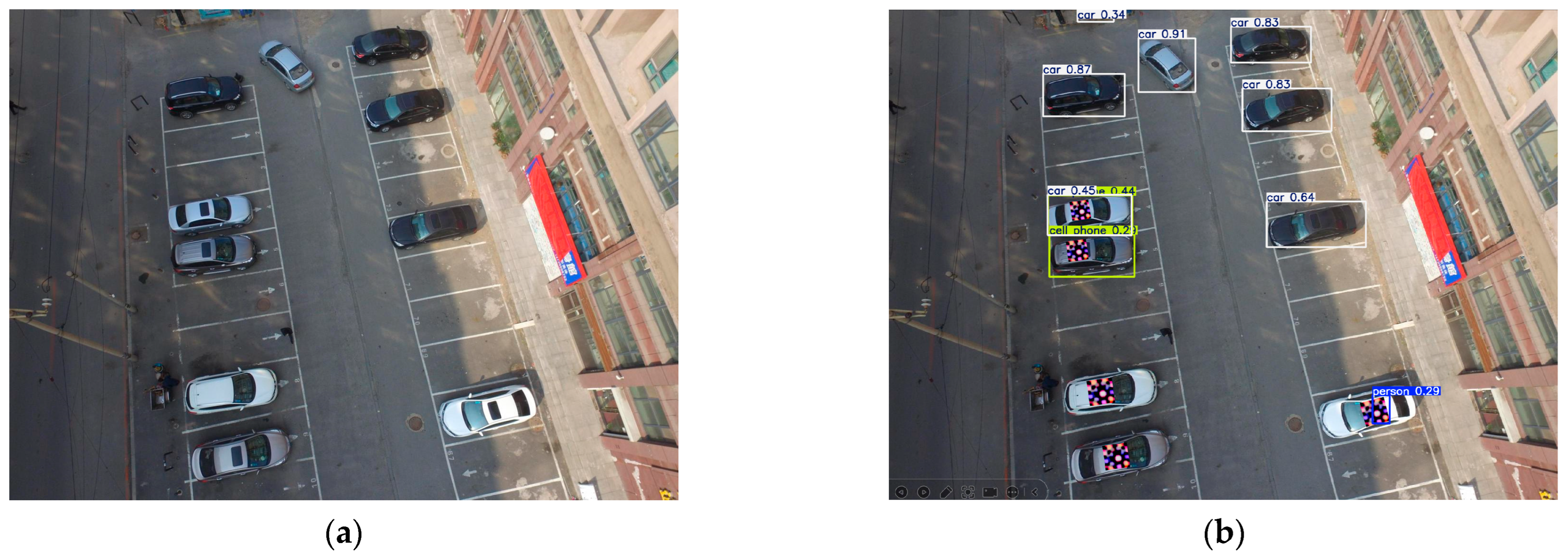
Figure 1. The impact of adversarial patch on the object detection of UAV. (a) The object detection of UAV on clean image. (b) The object detection of UAV on adversarial patches.
Machines 13 01060 g001
Figure 2. Low-frequency robust adversarial patch generation framework.
Machines 13 01060 g002
Figure 3. Progressive training strategy.
Machines 13 01060 g003
Figure 4. Effect of Frequency separation.
Machines 13 01060 g004
Figure 5. The spatial distribution of the color pools. (a) Original color 3D distribution. (b) DACP color 3D distribution.
Machines 13 01060 g005
Figure 6. Comparison of attack effects between the random patch and adversarial patch. (a) The effect of random patch. (b) The effect of LFRAP.
Machines 13 01060 g006
Figure 7. Patch shapes under different conditions. (a) Random Patch, (b) Normal Patch, (c) +Anti-Motion Blur, (d) +Frequency Separation, and (e) LFRAP.
Machines 13 01060 g007
Figure 8. Comparison of frequency components of the two patches.
Machines 13 01060 g008
Figure 9. (a) The changes in the components of each frequency band after the normal patch is disturbed by motion blur. (b) The changes in the components of each frequency band after the LFRAP is disturbed by motion blur.
Machines 13 01060 g009
Figure 10. Comparative Analysis of Spectra and SSIM after Interference.
Machines 13 01060 g010
Figure 11. Comparison of ASR of the two patches for different levels of blurring interference.
Machines 13 01060 g011
Table 1. The strategy of DACP.
Filtering LeverCriteria for JudgementParameter Settings
Saturability S H S V 0.2 , 0.8 S = m a x R , G , B m i n R , G , B m a x R , G , B
Print compatibility C M Y K 0 , 1 4 Use the US Web Uncoated ICC profile
Color difference constraint Δ E δ Dynamic threshold δ = 0.12 (color difference) [28]
Table 2. Comparison of SSIM Values with Two Different Color Pools.
Number of SamplesRandom Color Pool
(Mean ± Standard Deviation)
DCPAM
(Mean ± Standard Deviation)
Improvement Range
500.812 ± 0.0320.887 ± 0.0219.2%
1000.798 ± 0.0380.901 ± 0.01812.9%
1500.785 ± 0.0410.914 ± 0.01516.4%
2000.776 ± 0.0450.923 ± 0.01218.9%
15800.781 ± 0.0520.917 ± 0.02318.4%
Table 3. Comparison of the ASR of Patches under the Same Interference Conditions.
TypesASR (%)
Small SizeMedium SizeLarge SizeAverage
Normal Patch
(Baseline)
47.145.544.045.5
+Anti-Motion Blur59.557.258.358.3
+Frequency Separation58.958.262.459.8
LFRAP
(Ours)
65.264.164.864.7
Table 4. Comparison of the ASR of the LFRAP under Different YOLO Models and Blur Intensities.
ModelsL = 0L = 1L = 2L = 3ASR Decline Rate
(L = 0 → L = 3)
YOLOV385.680.173.465.919.7%
YOLOV5s89.285.378.771.517.7%
YOLOV5m87.883.977.269.118.7%
YOLOV5l84.582.175.867.319.2%
Table 5. Comparison of Considered Dimensions among Different Works.
MethodsThys et al. [25]Du et al. [23]URAdv [9]Ours (LFRAP)
Anti-Motion-Blur××
Color Adaptation×××
Frequency Optimization×××
Regarding the UAV Scenario×
Physical Degradation Modeling×
Disclaimer/Publisher’s Note: The statements, opinions and data contained in all publications are solely those of the individual author(s) and contributor(s) and not of MDPI and/or the editor(s). MDPI and/or the editor(s) disclaim responsibility for any injury to people or property resulting from any ideas, methods, instructions or products referred to in the content.