Article

Mechanism Design of Lower-Limb Rehabilitation Robot Based on Chord Angle Descriptor Method

1
School of Mechanical Engineering, Southwest Jiaotong University, Chengdu 610031, China
2
Sichuan Pronvincial Engineering Research Center of Cutting Technology of High-Temperature Alloys, Sichuan Polytechnic University, Deyang 618000, China
3
Sichuan University–Pittsburgh Institute, Sichuan University, Chengdu 610207, China
*
Author to whom correspondence should be addressed.
Machines 2025, 13(11), 1059; https://doi.org/10.3390/machines13111059
Submission received: 15 October 2025 / Revised: 9 November 2025 / Accepted: 15 November 2025 / Published: 17 November 2025

Abstract

The rapid aging of the global population and the escalating prevalence of conditions such as stroke and spinal cord injuries are driving an urgent demand for effective lower-limb rehabilitation. This necessitates the development of robotic devices capable of providing intensive, repetitive, and consistent movement therapy, with superior stability and safety being paramount. This paper presents a comprehensive design and modeling framework for a novel lower-limb rehabilitation robot, addressing the critical gap between computational complexity and model fidelity in gear-linkage mechanisms. A single-degree-of-freedom gear-five-bar mechanism synthesized via a Chord Angle Descriptor method is proposed that enables efficient, normalized-trajectory generation for standing motions. Subsequently, a hybrid dynamic modeling framework is developed, which explicitly incorporates time-varying gear mesh stiffness—a factor typically oversimplified in traditional models. By decomposing stiffness via a Finite Element Method-based potential energy analysis, characterizing it with a Fourier series, and integrating it into a Lagrangian model, our approach accurately captures complex dynamics with minimal degrees of freedom. Computational validation confirms exceptional stability, with a maximum gear angular amplitude below 0.003145 radians for a 250 kg user. This study provides both a robust theoretical foundation and a practical design paradigm for high-performance rehabilitation robots.

1. Introduction

The rapid aging of the population and the escalating prevalence of conditions such as stroke and traffic accidents are significantly augmenting the need for lower-limb rehabilitation robots. The development and manufacturing of lower-limb rehabilitation robots with superior performance, remarkable stability, and heightened safety have emerged as a significant objective. The development of lower-limb rehabilitation robots has been driven by the need to provide intensive, repetitive, and consistent movement therapy. Contemporary devices can be broadly categorized into several archetypes based on their mechanical structure and training modality:
  • Treadmill-based Gait Trainers
    These systems often integrate a body-weight support system with a robotic exoskeleton on a treadmill. The most prominent example is the Lokomat (Hocoma, Switzerland) [1], a driven gait orthosis that guides the patient’s legs on a predefined physiological walking path. Its linkage lengths are adjustable to accommodate different patient anthropometries. While highly effective for gait pattern training, such systems are typically large, expensive, and confine training to a fixed location on a treadmill, lacking overground walking transfer.
  • Overground Exoskeletons
    Devices like LOPES (University of Twente, Netherlands) [2,3] are lightweight, wearable exoskeletons designed for overground walking assistance. LOPES employs compliant actuators to enable a more natural gait and provide task-specific training. However, the accuracy of torque and position measurements for precise dynamic analysis can be a challenge, and the control system complexity increases with the number of degrees of freedom.
  • End-effector and Stationary Motion Trainers
    This category includes devices where the patient’s limb interacts with a robot at a single point (the end-effector), such as the footplate. The Rutgers Ankle (University of Rutgers, USA) [4,5] is a notable example, using a Stewart platform to provide resistance and assistance across the ankle’s range of motion. While compact and capable, parallel manipulators like the Stewart platform can have complex control issues and limited workspace. Other research has focused on stationary linkage-based trainers, such as the single-DOF six-bar mechanism for sit-to-stand training [6], which prioritize control simplicity and cost-effectiveness for specific motions.
  • Ankle/Foot-specific Rehabilitation Devices
    Significant research has targeted the ankle joint due to its complexity. Devices range from redundant parallel mechanisms [7] to cable-driven systems [8]. While these can offer high torque and precise control within a specific workspace, challenges remain, including cable sag, platform stiffness management, and ensuring alignment with the patient’s natural ankle axis to avoid discomfort.
A clear trade-off exists in the literature: high-DOF, multi-joint systems offer comprehensive training but are complex and costly, while simpler, single-DOF or joint-specific devices offer reliability and ease of control but may lack motion variety (as summarized in Table 1). There is a distinct need for devices that strike a balance—providing a functional, biomimetic trajectory for a key activity of daily living (like sit-to-stand) with inherent stability, simple control, and the potential for patient-specific customization without prohibitive cost or complexity. This gap motivates the design and modeling approach presented in this paper.
The gear-linkage coupled series mechanism integrates gear rotation with linkage motion, reducing degrees of freedom for improved control and enabling complex motion characteristics [11,12,13]. Furthermore, adjusting the gear transmission ratio allows for the regulation of the motion characteristics of the linkage. Thus, utilizing this mechanism for rehabilitation training and assisted standing in lower-limb robots is considered a viable method. The gear functions as a crucial component, transmitting power, altering velocity ratios, and controlling motion patterns, therefore greatly affecting the robot’s dynamic stability. A multitude of scholars have rigorously examined the gear mechanics of lower-limb rehabilitation robots to enhance comfort and stability while reducing vibration. Sun et al. [14,15] introduced a prosthetic knee joint employing a gear-five-bar mechanism, analyzing the influence of gear ratios on the instantaneous centerline of the prosthetic knee. Yu et al. [16] created a robotic mechanism for lower-limb rehabilitation that incorporates an epicyclic gear train and an open-linkage system, with parameter adjustments facilitated by genetic algorithms. Li et al. [17] employed Fourier transform techniques to create a lower-limb rehabilitation robot with supported standing capabilities, utilizing a gear-five-bar mechanism.
The referenced material mostly highlights the implementation of rehabilitative training responsibilities. The divergence between rehabilitative training trajectories and mechanism execution trajectories may cause additional harm to patients. This study introduces a chord angle descriptor technique to synchronize rehabilitation training trajectories, enhancing the safety and effectiveness of lower-limb rehabilitation robots. A gear-five-bar system for a lower-limb rehabilitation robot designed to assist with standing has been built using this technology.
Gears serve as the primary mechanism in lower-limb rehabilitation robotic systems, facilitating weight support and power transmission. The accuracy and smoothness of their movement often determine the system’s dynamic performance. Many researchers consider gears as rigid bodies, focusing on trajectory planning, mechanism dimension synthesis, and profile synthesis for lower-limb rehabilitation robots, while overlooking the impact of gear flexibility on the system’s dynamic stability [16,18]. Literature indicates that the stiffness of gear mesh varies with the rotation of gear pairs, potentially resulting in resonance and other issues. Neglecting gear flexibility may lead to system instability, hence posing potential risks to patient safety during usage and rehabilitation training [19].
Gear mesh stiffness is considered a vital internal excitation in dynamic gear models. Thus, accurate calculation of gear mesh stiffness is crucial for evaluating the dynamic stability of lower-limb rehabilitation robots. The primary methods for assessing gear mesh stiffness are the energy approach [20,21,22,23,24], analytical method [25,26], and the finite element method [27,28,29,30,31,32,33,34,35]. The finite element method has become the predominant methodology for assessing gear mesh stiffness owing to its enhanced accuracy and computational economy. Current research on gear flexible dynamics mostly focuses on the examination of the mesh stiffness of a single gear pair or gear train. There is a lack of methodologies for evaluating the impact of gear flexibility on the dynamic performance of gear-linkage systems in lower-limb rehabilitation robots.
This study addresses a critical gap in the dynamic modeling of gear-linkage mechanisms for rehabilitation robotics, where traditional models often oversimplify by neglecting the time-varying nature of gear mesh stiffness, while full finite element models become computationally prohibitive. The primary innovation of this work is a novel modeling paradigm that achieves an optimal balance between fidelity and simplicity. The main contributions are:
  • A novel trajectory synthesis method for rehabilitation robotics: We introduce a planar trajectory synthesis method based on the chord angle descriptor. This method leverages the descriptor’s invariance to rotation, translation, and scaling, allowing for the direct extraction of trajectory shape characteristics independent of the mechanism’s installation pose or size. This innovation eliminates the need for trajectory normalization and interval design parameters, thereby resolving the issues of large computational load, low retrieval efficiency, and substantial data storage in open-loop trajectory synthesis for rehabilitation robots.
  • A hybrid dynamic modeling framework for gear-linkage mechanisms: We develop a novel dynamic modeling approach that integrates finite element analysis, Fourier series, and Lagrangian dynamics. This framework explicitly incorporates the time-varying gear mesh stiffness—a critical factor often neglected in traditional models—through a feature decomposition process. It successfully bridges the gap between the prohibitive computational complexity of full-system FEM models and the oversimplification of traditional models, achieving high accuracy with a minimal number of degrees of freedom. We present the complete design and stability analysis of a single-degree-of-freedom gear-five-bar mechanism, offering a theoretical and practical solution for clinical rehabilitation.

2. Methods and Experiments

2.1. Trajectory Acquisition of Lower-Limb Rehabilitation Motion

The motion trajectory of the hip joint was established as the primary requirement for the design of the lower-limb rehabilitation robot mechanism. A fixed-size circular marker was attached to the user’s hip joint, followed by the recording of the standing motion. To balance subject comfort and methodological rigor, markers were placed on the exterior of the clothing. However, to mitigate the artifact of clothing elasticity—a known source of error in motion capture—a specific attachment protocol was followed. Each marker was affixed to a rigid base, which was then directly bonded to the skin using double-sided adhesive tape through a small opening in the garment. This created a local mechanical link that bypassed the elastic properties of the clothing, ensuring that the marker trajectory faithfully represented the underlying body movement during slow motion. Consequently, the influence of clothing elasticity on the hip joint trajectory data was considered negligible for the accuracy requirements of this study, which focuses on gross motion patterns for rehabilitation mechanism synthesis. A high-resolution camera (8 megapixels) was used to record the sit-to-stand motion at a sampling frequency of 30 fps. The system’s tracking accuracy was validated to be within 1 mm in a controlled environment. The marker functioned as the target for the tracking technique, and the coordinates of the marker’s centroid were obtained using the mean shift method. Kalman filtering was employed on the coordinates obtained from each frame to determine the standing trajectory coordinates within the image coordinate system, which were subsequently converted into global coordinates. This methodology has been previously validated for rehabilitation trajectory acquisition in our earlier work [36,37]. The documented trajectory of hip joint movement in the lower limb serves as the target for mechanism design, as depicted in Figure 1.

2.2. Method for Chord Angle Descriptor

The chord angle descriptor is a symbolic representation of shape based on the characteristics of curve profiles [38]. As shown in Figure 2, the solid line P 1 P n represents the motion trajectory of a planar four-bar mechanism, and P = P 1 , P 2 , , P n is a sequence of sequentially sampled points at equal intervals along this trace curve. For any two non-repeating sampled points P i and P j on the curve, the chord angle θ i j can be defined as:
θ i j = P i P j , P j P m , i j > Δ 0 , i j Δ
where θ i j falls in the range of 0 , π . P m is another sampled point between P i and P j , which is defined by
P m = P j + Δ , i > j P j Δ , i j
where Δ is the index displacement parameter, P i P j , P j P m can be calculated using:
P i P j , P j P m = cos 1 P i P j · P j P m P i P j × P i P j
After converting θ i j to logarithmic space,
θ i j = log 1 + θ i j
for any two distinct sampling points on the trajectory in Figure 2, the chord angle constructed via Equations (1)–(4) yields the chord angle descriptor matrix A for the entire open-loop trajectory:
A = θ 11 θ 1 n θ k , k θ k , k + s θ k + s , k θ k + s , k + s θ n 1 θ n n
where n is the number of trajectory sampling points: k , s 1 , n , and 1 < k < n , 0 < s < n k .
The construction method of the chord angle descriptor clearly indicates that it does not necessitate a closed trajectory. Consequently, it may delineate the shape characteristics of both closed-loop and open-loop trajectories, establishing a basis for the application of the chord angle descriptor approach to the synthesis of open-loop trajectories in mechanisms. For the sake of clarity, the chord angle descriptor is always referred to as CAR (Chord Angle Representation) throughout this paper.

2.3. Trajectory Synthesis Based on the CAR Method

The specific process of querying the mechanism dimension type using the CAR graph library is as follows:
  • Compute the CAR matrix A α for the mechanism dimension type and establish the graph library.
  • Utilize multidimensional scaling transformation [39] and hierarchical clustering algorithms [40] to diminish dimensionality and cluster the CAR matrix of the library, thus creating a clustering tree for the library.
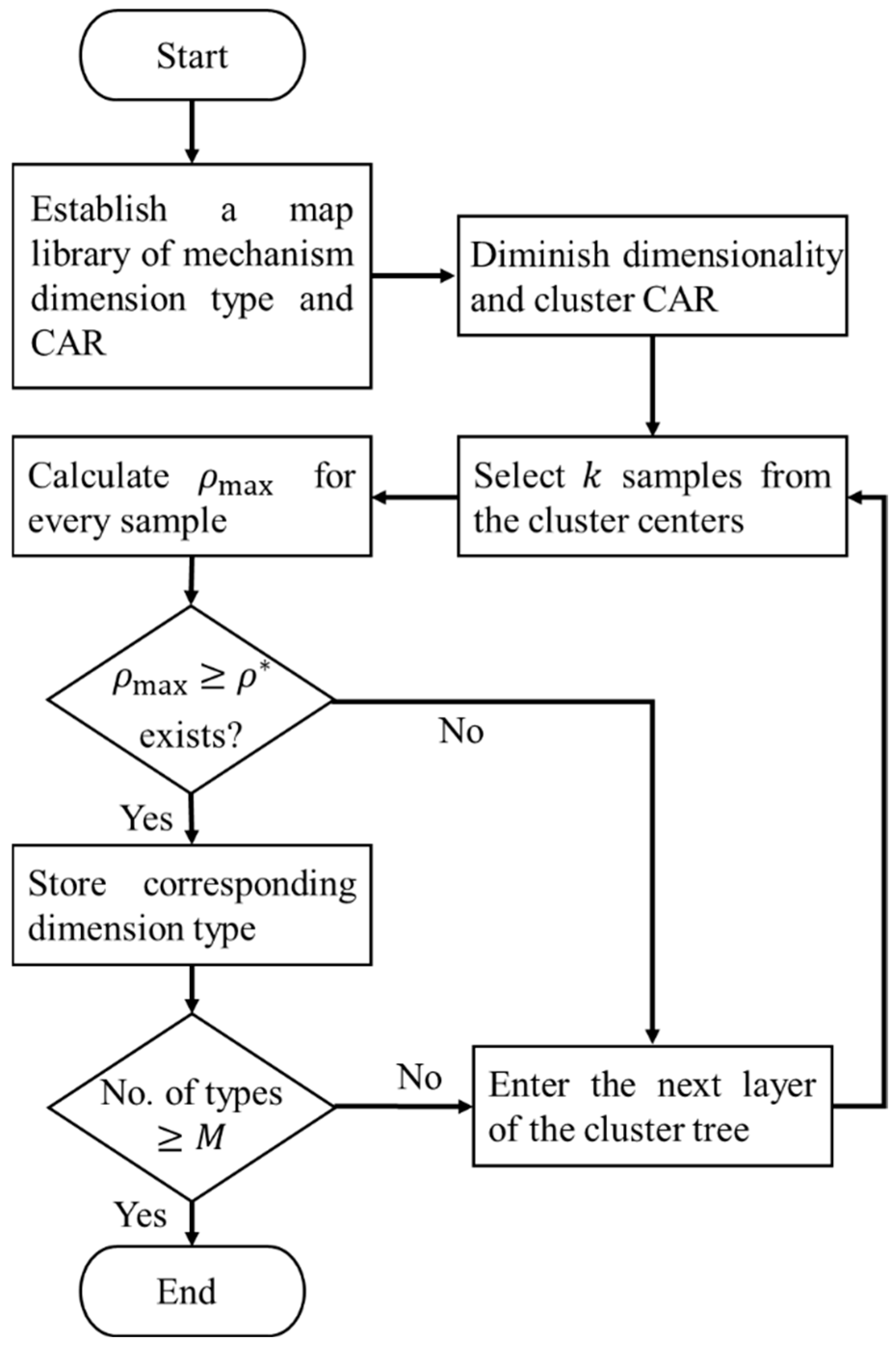
  • Given the target value ρ * and the number of mechanisms M , select k samples near the cluster centers. Calculate their similarity to the target trajectory’s CAR using
    ρ α , k = C o v A α , A β k D A α D A β k D A α = i = 1 α j = 1 α A α i j A α ¯ 2 D A β k = i = 1 α j = 1 α A β i j k A β ¯ 2 C o v A α , A β k = i = 1 α j = 1 α A α i j A α ¯ A β i j ( k ) A β ( k ) ¯
    A β ( k ) signifies the submatrix of the string angle descriptor matrix, whereas A α ¯ and A β ( k ) ¯ represent the averages of the total sum of all elements in their respective matrices, while D denotes the variance. The range of ρ α , k is [0, 1], a value approaching 1 indicates a greater similarity between the target trajectory’s form and the contour segment shape of that component of the mechanism trajectory, while a value nearing 0 signifies reduced similarity.
  • Ascertain the existence of a contour segment that meets the condition ρ m a x ρ * . If available, use this contour segment as the trajectory matching outcome and record its associated dimensional parameters as mechanism design parameters. If not present, advance to the subsequent level of the clustering hierarchy.
  • Repeat steps (3) and (4) until M matching mechanism dimension types are retrieved from the library.
Figure 3 depicts the flowchart of the aforementioned retrieval operation. This study selected ten samples near each cluster center for comparison. The map library construction on a PC equipped with an Intel i3-7100 processor operating at 3.9 GHz and 8 GB of RAM takes approximately 10 s. The dimensionality reduction and clustering of the map library necessitate around 2000 s, with an average retrieval time of about 15 s per cluster center. The time investment for dimensionality reduction and clustering is a single expense. Upon establishing the mechanism dimension type in the graph library, the chord angle descriptor for the motion trajectory is consequently determined, hence completely governing the clustering results of the graph library.

2.4. Design of Gear-Five-Bar Mechanism

The gear-five-bar mechanism is based on a two-degree-of-freedom five-bar hinge mechanism, which establishes a linkage between two input motions through the utilization of fixed-axis gear trains or peripheral gear trains attached to different links. This enables the mechanism to execute all requisite operational movements with a singular driving component. Unlike the comparable single-degree-of-freedom four-bar hinged linkage, the gear-five-bar linkage offers greater design flexibility and enables the realization of more complex motion paths.
The five-bar gear system can be categorized into three categories according to the gears’ mounting positions: fixed-axis, planetary, and differential gear train mechanisms, as depicted in Figure 4. The fixed-axis gear train five-bar mechanism incorporates both gears within the frame, ensuring a constant transmission ratio and enabling easy installation, thereby making it suitable for stable, periodic motion. In the planetary gear-five-bar mechanism, one gear is secured to the frame, while the other is connected to a link. The output trajectory of this mechanism has enhanced flexibility owing to the superposition of the gear’s motion with the link’s oscillation, enabling asymmetric and variable velocity motion. Nonetheless, the link experiences significant dynamic stresses, necessitating an evaluation of dynamic stability. In the differential gear-five-bar system, both gears are secured to the linkages. The gears are significantly affected by the acceleration of the linkage motion, resulting in increased dynamic loads and a tendency to generate impact forces.
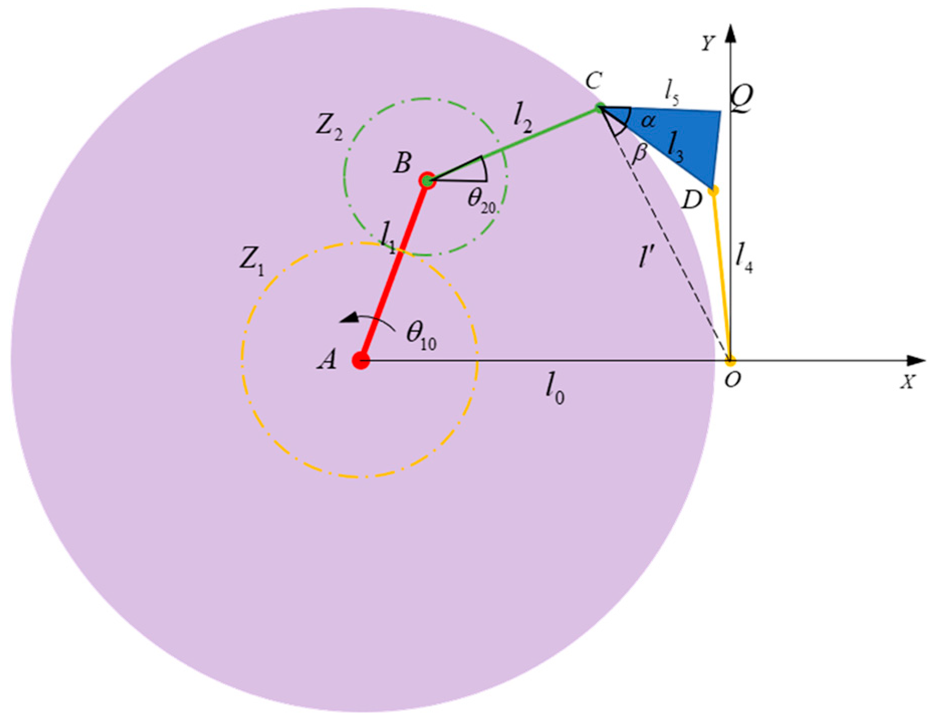
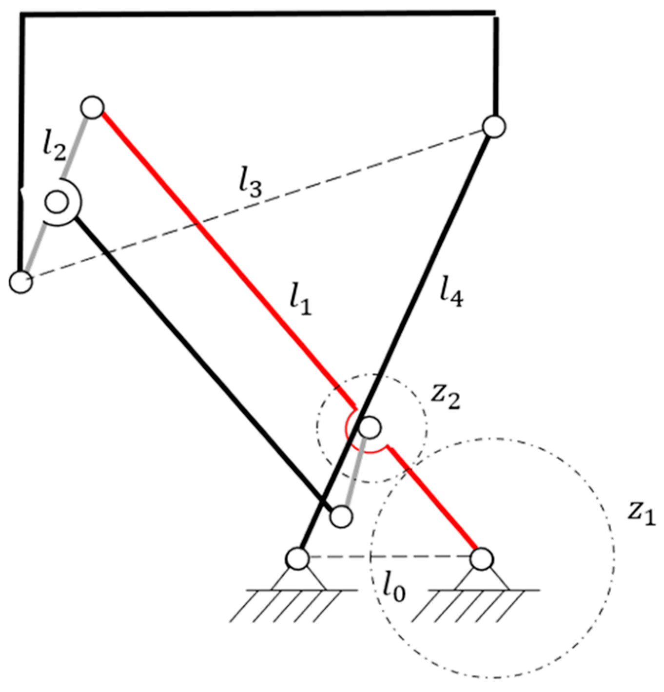
This study utilizes a planetary gear-five-bar mechanism from the numerical graph library to execute trajectory synthesis, considering the varied flexible shapes of human rehabilitative motion trajectories. Figure 5 illustrates the schematic diagram of the gear-five-bar mechanism within the numerical spectrum library. l 0 represents the frame length, l 1 signifies the driving rod length A B , l 2 indicates the connecting rod length B C , l 3 refers to the length C D within the rigid body C D Q , l 5 depicts the length of C Q , the angle between C Q and C D is α , and l 4 represents the length of the connecting rod O D . The motion trajectory of point Q signifies the comprehensive motion route of the mechanism. Proportional scaling of link lengths results solely in proportional scaling of the motion trajectory without modifying its shape; therefore, dimensionless relative link lengths—specifically r 0 = l 0 / l 0 = 1 , r 1 = l 1 / l 0 , r 2 = l 2 / l 0 , r 3 = l 3 / l 0 , r 4 = l 4 / l 0 , and r 5 = l 5 / l 0 —can be utilized as geometric parameters to eliminate database redundancy.
Additionally, since the gear tooth ratios between z 1 and z 2 , and the initial mounting angles of the gears differ, the motion trajectories of the mechanism will also vary. Therefore, the database must also store the gear tooth ratios z = z 1 / z 2 , as well as the initial values θ 10 and θ 20 of the angles θ 1 and θ 2 , respectively. Consequently, in the coordinate system depicted in Figure 5, the motion trajectory of point Q can be articulated as the function
x Q , y Q = f r 1 , r 2 , r 3 , r 4 , r 5 , z , θ 10 , θ 20
where x Q , y Q denotes the coordinates of point Q . Once the above parameters are determined, for any given angle θ 1 of the driving link, the coordinates x Q , y Q of point Q are also uniquely determined.
This study derives the full rotation condition for the gear-five-bar mechanism to ensure that driving link A B can achieve a complete rotation. For simplification of derivation, it is evident from the figure that the rotational frequency f 1 of link A B and the rotational frequency f 2 of link B C adhere to the relationship:
f 2 f 1 = z 2 z 1 + 1
Thus, in the local coordinate system X O Y , vector O C can be represented as:
O C = i = 0 2 l i e j 2 π f i + θ i
where f 0 = 0 , and θ 0 = π . As shown in Figure 5, if the drive rod A B of this gear-linkage mechanism can rotate through a full circle, then at any moment during the mechanism’s motion, O C D will form a triangle:
l 3 l 4 l l 3 + l 4
where l is the length of C D .
During the motion of the mechanism, l changes with the maximum l m a x and minimum l m i n , respectively. For the gear-five-bar mechanism during its rotation cycle, Equation (10) holds at any given moment. Therefore, the following condition must be satisfied:
l 3 l 4 l m i n l m a x l 3 + l 4
Thus, the feasible range for l 3 and l 3 should follow:
l 4 l m a x l m i n 2 max l m a x l 4 , l 4 l m i n , l m a x l m i n 2 l 3 l 4 + l m i n
or
l 3 l m a x l m i n 2 max l m a x l 3 , l 3 l m i n , l m a x l m i n 2 l 4 l 3 + l m i n
Correspondingly, the necessary and sufficient condition for a gear-five-bar mechanism to achieve full rotation is that its link length parameters satisfy either Equation (12) or Equation (13). To further enrich the trajectory shapes in the kinematic library and minimize redundant dimensional types to save storage space, similar to the hinged four-bar mechanism, the parameter r 1 ~ r 4 can be allowed to vary non-uniformly near 1. Specifically, the variation of r 1 ~ r 4 is governed by a log-normal distribution:
ln Y ~ N 0,0.6 ,         Y = r 1 , r 2 , r 3 , r 4
and r 5 follows:
r 5 ~ N 0,0.2
Let θ 10 , θ 20 , and α vary uniformly within the range 2 π , 2 π while restricting the gear ratio z to be a positive integer, thereby generating 16,000 sets of gear-five-bar mechanisms with different dimension configurations.
For each parameter set, rotate the drive link A B counterclockwise to obtain the Q -point motion trajectories of the gear-five-bar mechanisms of varying dimensions. Each trajectory comprises 50 evenly distributed sampling points. Upon acquiring the motion trajectories, calculate the CAR matrix for each trajectory with the methodology outlined in Section 2.2. This produces 16,000 sets of 50 × 50-dimensional CAR matrices, so creating a numerical graph library for the gear-five-bar mechanism.

2.5. Calculation of Time-Varying Mesh Stiffness via Potential Energy Method

Gear stiffness encompasses Hertzian contact stiffness k h , bending stiffness k b , shear stiffness k s , axial compression stiffness k a , and tooth root stiffness k f . Based on the strain energy formula in elasticity theory, the Hertzian potential energy U h , bending potential energy U b , shear potential energy U s , axial compression potential energy U a , and tooth root potential energy U f can be derived as follows:
U h = F 2 2 k h , U b = F 2 2 k b , U s = F 2 2 k s , U a = F 2 2 k a , U f = F 2 2 k f
where F is the mesh force on gear mesh surfaces. And the strain energy per gear pair can be expressed as:
U = F 2 2 k = U h + U b 1 + U s 1 + U a 1 + U f 1 + U b 2 + U s 2 + U a 2 + U f 2 = F 2 2 1 k h + 1 k b 1 + 1 k s 1 + 1 k a 1 + 1 k f 1 + 1 k b 2 + 1 k s 2 + 1 k a 2 + 1 k f 2
where k represents the equivalent mesh stiffness for a single gear pair, with subscripts 1 and 2 denoting the pinion and the gear wheel, respectively. The mesh stiffness for a single gear pair can be calculated using the single gear pair formula:
k = 1 1 k h + 1 k b 1 + 1 k s 1 + 1 k a 1 + 1 k f 1 + 1 k b 2 + 1 k s 2 + 1 k a 2 + 1 k f 2
A hybrid hexahedral (for the gear teeth) and tetrahedral mesh (for others) was utilized to improve computational efficiency and accuracy for the gear pair. The contact areas between the teeth were enhanced using a finer mesh. Figure 6 illustrates the finite element model consisting of 619,513 nodes and 667,800 elements. A fixed constraint was imposed on the base of the gear wheel in the lower-limb rehabilitation robot, limiting its rotational and translational degrees of freedom based on the gear transmission circumstances. A rigid coupling constraint was implemented between the inner surface of the pinion’s central aperture and the reference point of the rotational axis. Surface-to-surface interaction was implemented between the teeth of the pinion and the gear wheel, with the sliding formulation configured to finite sliding. A torque of 100 N·m was exerted on the pinion [33,41].

2.6. Dynamic Analysis of Gear-Linkage Mechanisms Considering Gear Elasticity

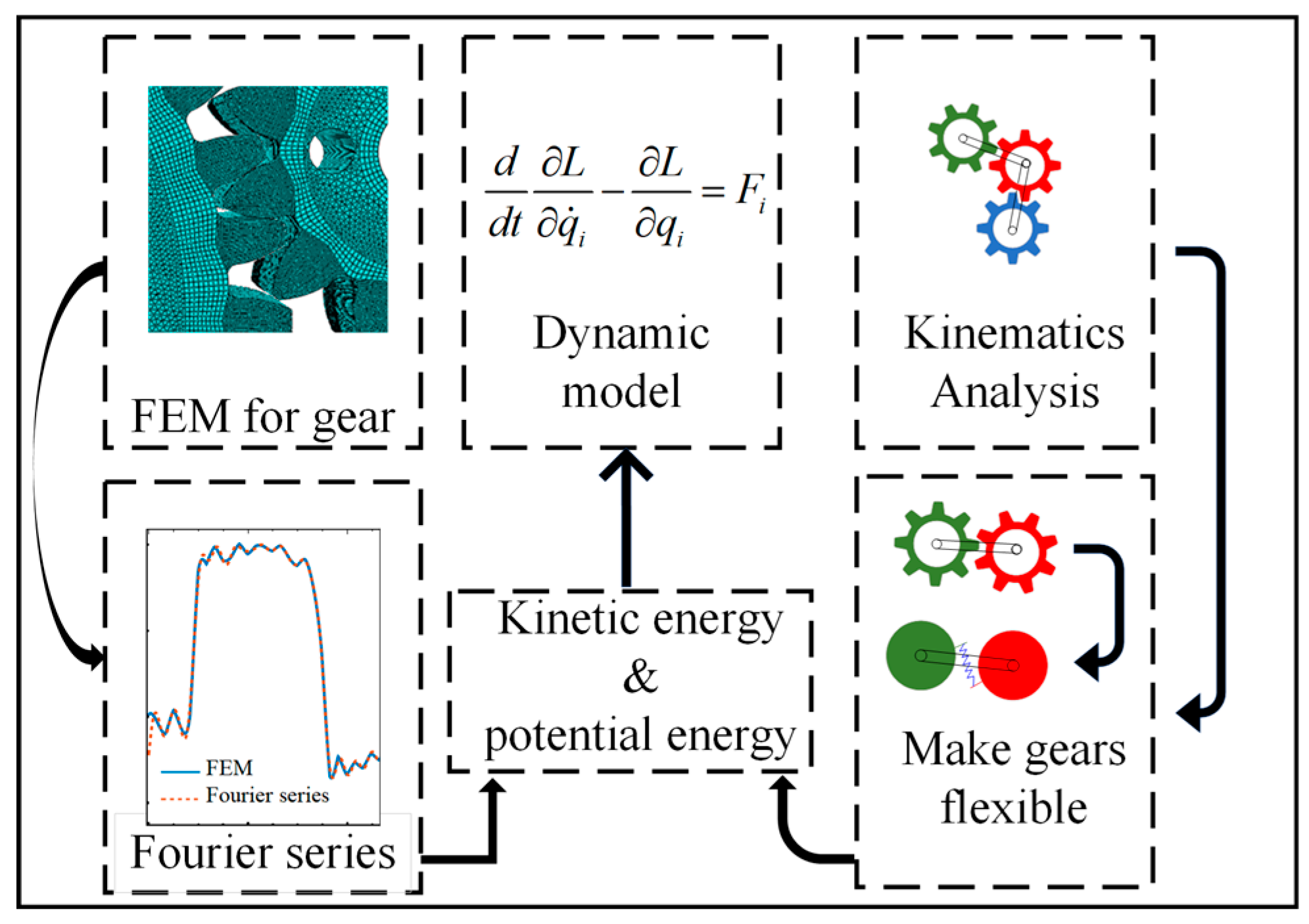
The components in a gear-linkage mechanism are linked via gears, often forming composite mechanisms with supplementary systems, resulting in complex kinematic interactions among the various links. The modeling and analysis of gear elasticity present greater challenges than those related to conventional gear trains or connections. Nonetheless, the restricted vibration amplitude of gear teeth can be leveraged to enhance the understanding of the dynamic system. This study presents a dynamic modeling approach for gear-linkage coupled systems that achieves a compromise between accuracy and simplicity through the characteristic decomposition of gear mesh stiffness. Finite element analysis is employed to obtain the stiffness variation curve of the gear pair. Fourier series is utilized to describe the characteristics of stiffness variation, which represent the elastic potential energy of the system. The Lagrangian equations are utilized to obtain the dynamic equations for the gear-linkage system. This approach mitigates the issue of excessive degrees of freedom linked to the analysis of gear-linkage mechanisms using finite element models. It enables an accurate representation of the dynamic effects of stiffness on the gear-linkage mechanism using a limited number of degrees of freedom.
Figure 7 illustrates the dynamic analysis of the gear-linkage system, incorporating gear elasticity. Initially, it is essential to calculate the mesh stiffness for all interacting gears in the mechanism due to the fluctuation of mesh stiffness between any two gears based on their respective angular positions. This study promotes the application of the finite element method for this calculation, generating the stiffness variation curve in proportion to the rotation angle throughout a single mesh cycle. Secondly, assuming the mesh stiffness curve remains constant during each mesh cycle, a Fourier series is utilized to approximate the mesh stiffness curve for each gear. This phase aims to incorporate time-varying mesh stiffness into the dynamic models. Third, the equations of motion are derived for the system, assuming rigid gears, to represent the spatial positions of each mass element. Fourth, the gear flexibility is achieved by assuming spring mesh between two gears. Subsequently, new degrees of freedom are established to represent the relative displacement between gears. A kinematic model employing established equations of motion is utilized to delineate the kinetic and potential energies of system components, integrating these additional degrees of freedom. The elastic potential energy is calculated using gear mesh stiffness curves represented by a Fourier series. The kinetic and potential energies are integrated into the Lagrangian equations, yielding the system’s dynamic model.

3. Results and Discussion

3.1. Trajectory Synthesis

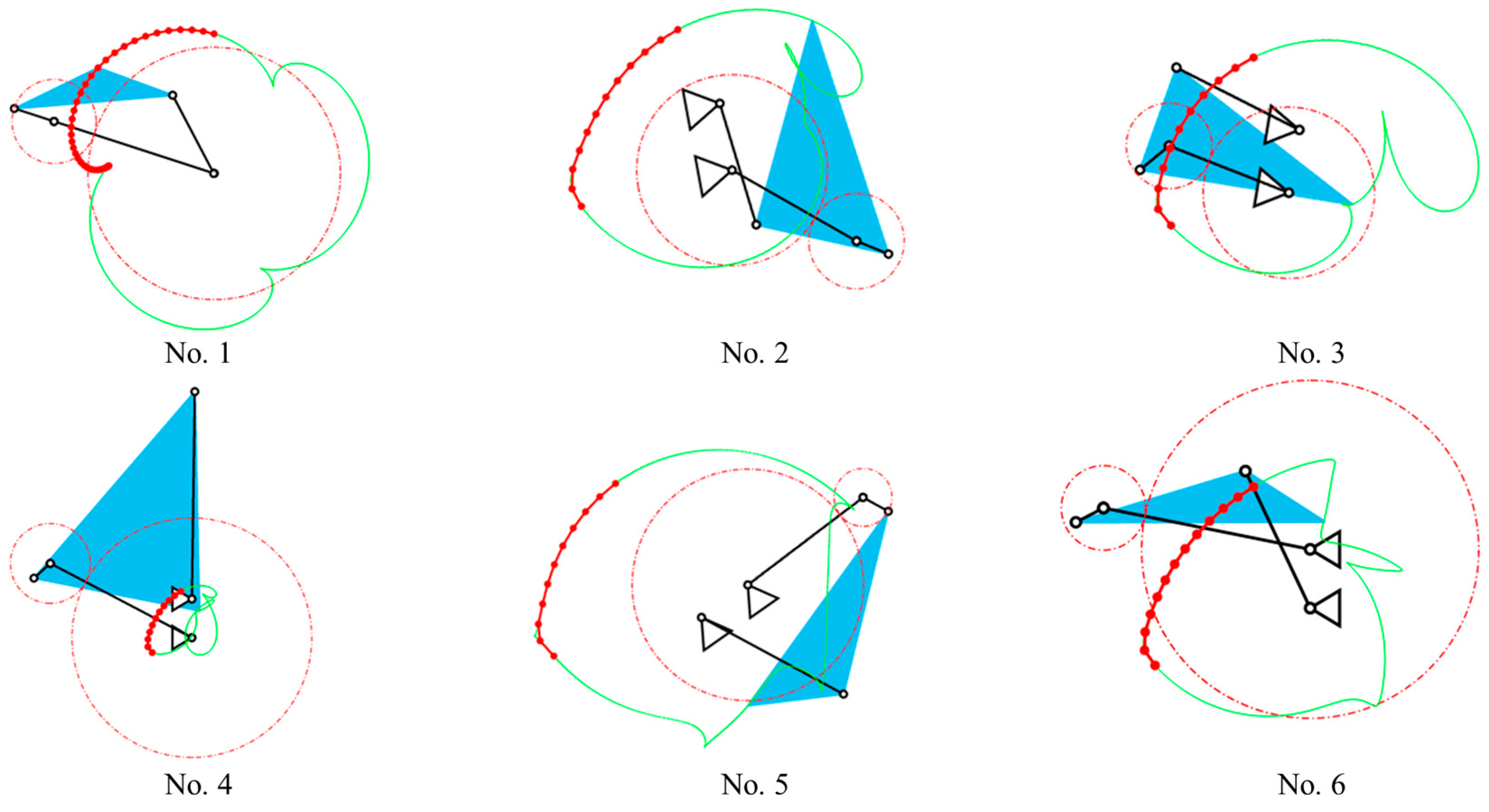
Figure 8 illustrates the hip joint trajectory of the lower-limb rehabilitation robot depicted in Figure 1. Trajectory synthesis was conducted with CAR descriptors, as outlined in Section 2.2. Through the delineation of design specifications and the quantity of mechanisms, six sets of mechanisms closely resembling the desired trajectory were extracted from the established gear-five-bar mechanism database, as shown in Figure 9. The green curve illustrates the motion trajectory of the mechanism, whilst the red curve segments denote the sections of the mechanism’s trajectory that most closely align with the target trajectory curve. Specific design parameters for the six synthesized trajectories are presented in Table 2. From the similarity calculation via Equation (6), No. 1 was selected for the following mechanism design.

3.2. Mechanical Design of Lower-Limb Rehabilitation Robot

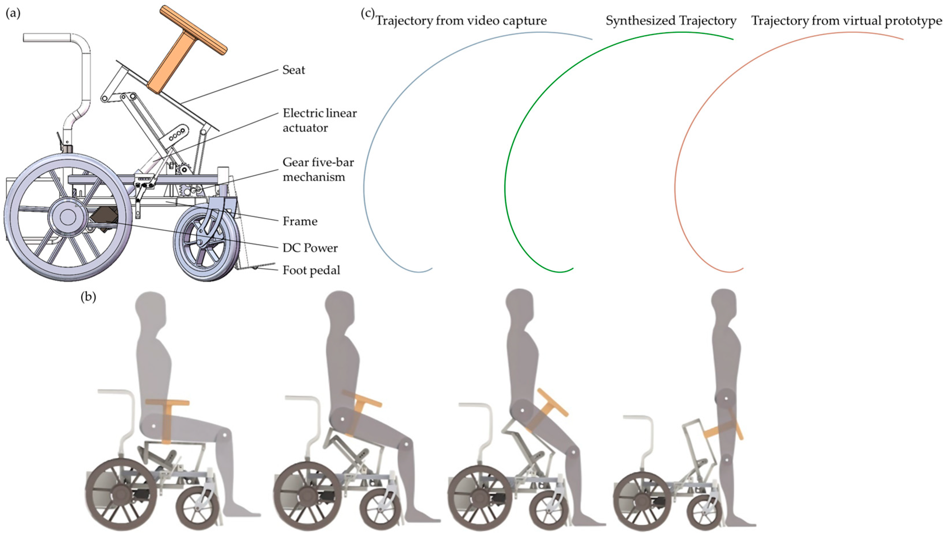
The optimal similarity for trajectory synthesis, derived from the comprehensive results of the mechanism, corresponds to a gear ratio of 3 for the gear transmission system. A parallelogram mechanism was devised to enhance stability, rigidity, and load-bearing capacity. The primary gear is secured to the frame, while the secondary gear is connected to the parallelogram mechanism via a rotary joint. In contrast, the design of the parallelogram mechanism reduces the center distance of the gear pair, the mechanism’s mass, and the gear module. This improves transmission fluidity and reduces the intricacy of gear manufacturing. Simultaneously, it optimizes the gear installation space, hence facilitating gear mounting and assembly. Figure 10 depicts the schematic representation of the mechanical architecture of the developed lower-limb rehabilitation robot.
Considering the installation area of the gear pair, manufacturing and assembly tolerances, strength, and stiffness, the gear wheel comprised 38 teeth, whilst the pinion contained 12 teeth. The gear wheel employed truncated teeth to facilitate installation. Because the pinion has fewer than 17 teeth, both gears used modified teeth to avert root cutting during machining. The radial modification coefficient was −0.47 for the gear wheel but 0.47 for the pinion. To enhance the strength while considering uniform wear of the pinion, process equivalence, and assembly error compensation, the tooth width of the pinion was 5–10 mm wider than that of the gear wheel. Table 3 delineates the precise structural specifications for each gear. Figure 11 illustrates the mechanics of the lower-limb rehabilitation robot.

3.3. Evaluation of Time-Varying Mesh Stiffness

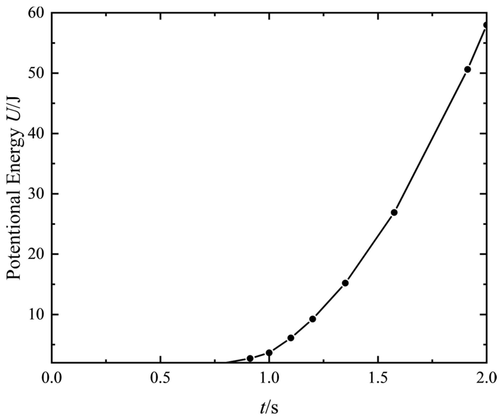
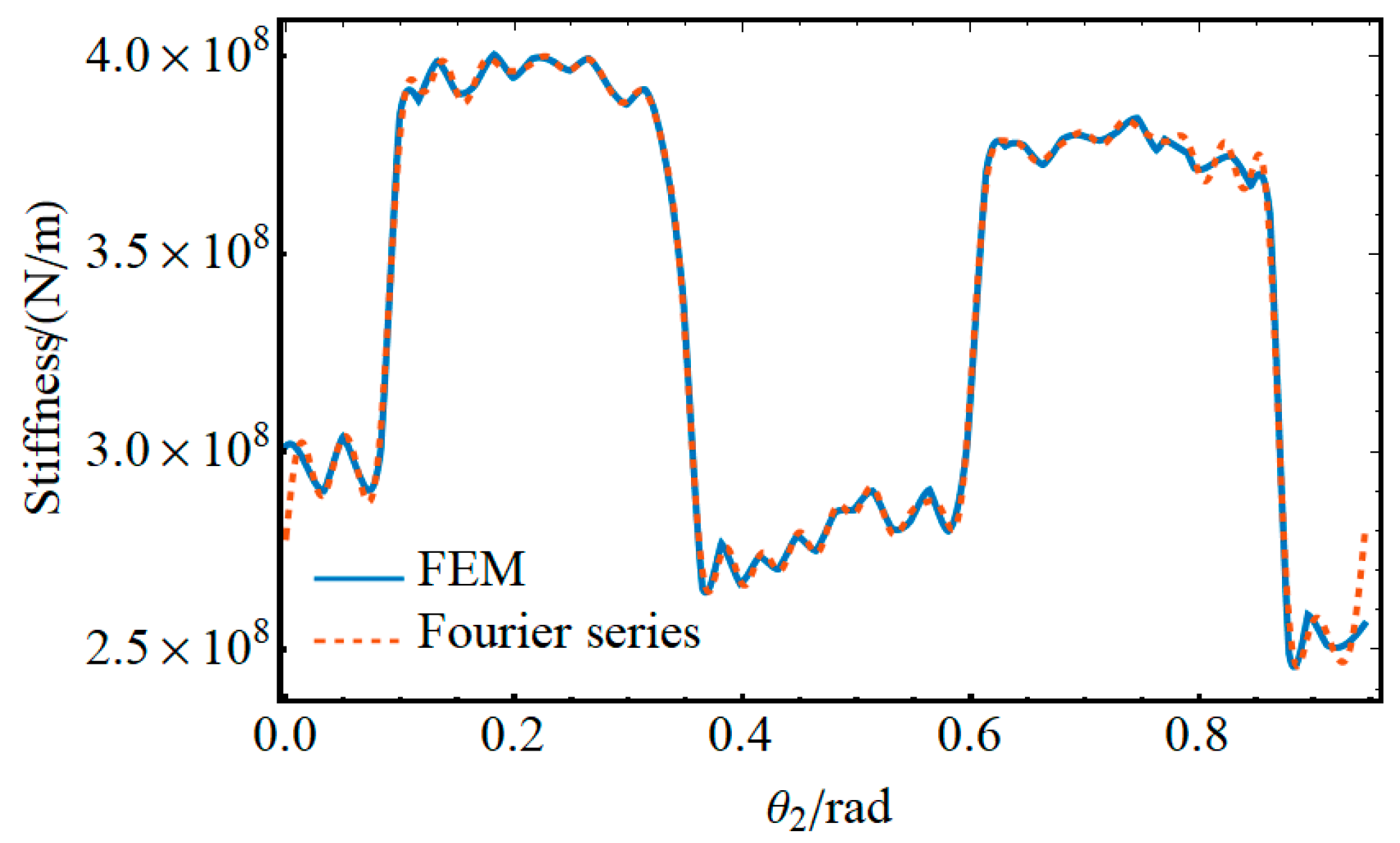
Figure 12 delineates the calculated potential energy U . The gear mesh stiffness k is determined using the formula U = F 2 / 2 k . The mesh location is modified according to the gear ratio between the pinion and the ring gear. The time-varying mesh stiffness of the gears was derived as seen in Figure 13.

3.4. Dynamic Model of the Lower-Limb Rehabilitation Robot Mechanism System

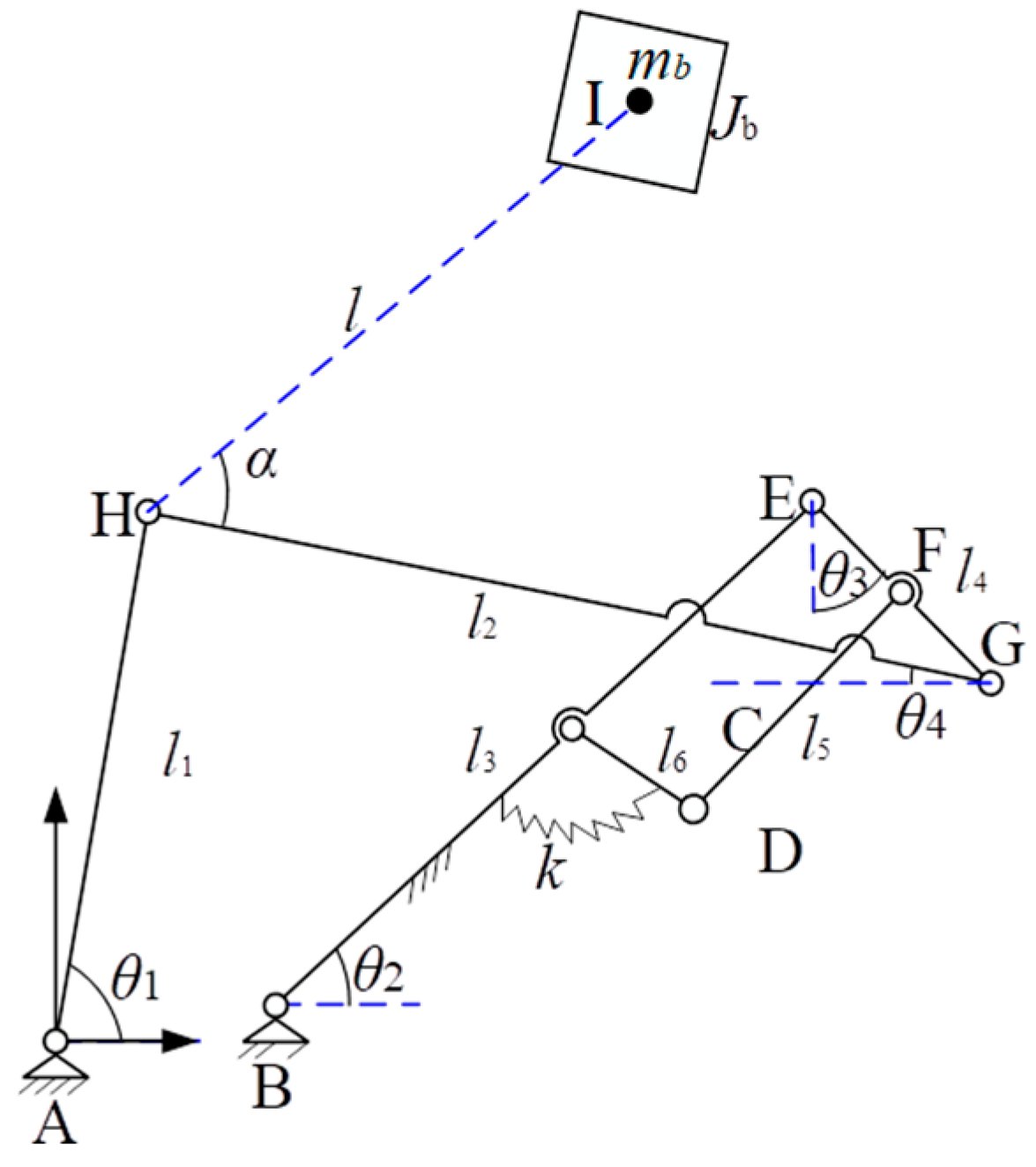
The simplified diagram of the gear-linkage mechanism for the lower-limb rehabilitation robot system is shown in Figure 14, where the prime drive is the push rod P Q . Let the length of P Q be P Q m i n when the patient is in a seated position. The motion law of the push rod can be expressed as:
P Q = P Q m i n   + v p t
So, the angle between B Q and B P :
P B Q = cos 1 B P 2 + B Q 2 P Q 2 2 B P B Q
Since the sum of P B Q and the angle between B P and the horizontal plane is 0.6981317 rad,
θ 2 = P B Q 0.6981317
Based on the geometric relationship, the rotational velocity ratio between rod B E and the pinion in the mechanism always satisfies the following condition:
θ 2 ˙ = 6 23 θ 3 ˙
As θ 2 = 0.49   rad when θ 3 = 0 , the following relationship must be satisfied:
θ 2 = 6 23 θ 3 + 0.49
Correspondingly, based on geometric constraint,
B E = l 3 cos θ 2 , l 3 sin θ 2 ,   E G = l 4 sin θ 3 , l 4 cos θ 3
The coordinates of point G can be obtained as:
A G = x G , y G = x B + l 3 cos θ 2 + l 4 sin θ 3 , y B + l 3 sin θ 2 l 4 cos θ 3
Given that the lengths of A H and H G remain unchanged, point H satisfies the constraint equation:
x H 2 + y H 2 = l 1 2 x H x G 2 + y H y G 2 = l 2 2
Solving the above equation yields:
x H = x G l 1 2 l 2 2 + x G 2 + y G 2 y G x G 2 + y G 2 l 1 l 2 2 l 1 + l 2 2 x G 2 y G 2 2 x G 2 + y G 2 y H = y G l 1 2 l 2 2 + x G 2 + y G 2 x G x G 2 + y G 2 l 1 l 2 2 l 1 + l 2 2 x G 2 y G 2 2 x G 2 + y G 2
The coordinates of the H and G can be used to solve for θ 4 :
θ 4 = tan 1 y H y G x G x H
Finally, the coordinates of point I can be obtained as
A H + H I = x I , y I = x H + l cos α θ 4 , y H l sin α θ 4 = x H + l cos α cos θ 4 + sin α sin θ 4 , y H + l cos θ 4 sin α cos α sin θ 4 = x H + l cos α x G x H l 2 + sin α y H y G l 2 , y H + l x G x H l 2 sin α cos α y H y G l 2

3.5. Stability Analysis of Lower-Limb Rehabilitation Robot Mechanisms Considering Gear Flexibility

When gears undergo elastic deformation, the system can be converted into the computational model shown in Figure 15. Assuming elastic deformation occurs, local angular displacement Δ θ 3 develops on θ 3 , and it is straightforward to derive the following relationship:
x I θ 3 + Δ θ 3 = x I θ 3 + x I θ 3 Δ θ 3 + O Δ θ 3 2 Δ x I = x I θ 3 + Δ θ 3 x I θ 3 x I θ 3 Δ θ 3 d Δ x I d t d d t x I θ 3 Δ θ 3 + d d t Δ θ 3 x I θ 3 d d t Δ θ 3 x I θ 3 y I θ 3 + Δ θ 3 = y I θ 3 + y I θ 3 Δ θ 3 + O Δ θ 3 2 Δ y I = y I θ 3 + Δ θ 3 y I θ 3 y I θ 3 Δ θ 3 d Δ y I d t d d t y I θ 3 Δ θ 3 + d d t Δ θ 3 y I θ 3 d d t Δ θ 3 y I θ 3 θ 4 θ 3 + Δ θ 3 = θ 4 θ 3 + θ 4 θ 3 Δ θ 3 + O Δ θ 3 2 Δ θ 4 θ 3 + Δ θ 3 = θ 4 θ 3 + Δ θ 3 θ 4 θ 3 θ 4 θ 3 Δ θ 3 d Δ θ 4 d t d d t θ 4 θ 3 Δ θ 3 + d d t Δ θ 3 θ 4 θ 3 d d t Δ θ 3 θ 4 θ 3
Neglecting the mass of all components in the system except for the human body, the kinetic and potential energy of the system can be expressed as
T = 1 2 m b d Δ x I d t 2 + d Δ y I d t 2 + 1 2 J b d Δ θ 4 d t 2 1 2 m b y I θ 3 2 + x I θ 3 2 + J b θ 4 θ 3 2 d d t Δ θ 3 2 U = 1 2 k Δ θ 3 2
where k = r · k s , k s (variable stiffness during gear mesh) represents the relationship between the stiffness obtained from the finite element method and the angle between the two gears. For this example, this angle is equal to θ 2 . To apply this method in solving differential equations, the corresponding expression via Fourier series is as shown in Figure 16.
Following the Lagrangian equations,
L = T U
d d t L θ ˙ 3 L θ 3 = 0
the local vibration equation for the system can be obtained as:
d 2 d t θ 3 + k m b y G θ 3 2 + x G θ 3 2 + p b θ 4 θ 3 2 θ 3 = 0
where p b = J b / m b 0.15   m 2 . Taking human mass 50 kg as an example, Figure 17 shows the system response under the initial conditions with θ 3 ( 0 ) = 0.001 and θ 3 ( 0 ) = 0 .
Figure 17 illustrates that during the travel of the push rod, the system’s small-amplitude vibration escalates to nearly three times the original amplitude. This signifies that the system’s stability is at its lowest when the user is preparing to exit the wheelchair, requiring heightened vigilance to guarantee patient safety during this crucial phase.
Figure 18 depicts the correlation between the system’s maximum vibration amplitude and human mass, derived from solving the vibration equation for masses between 20 and 250 kg. The system’s maximum vibration amplitude demonstrates a consistent increase with more human mass. This suggests that system rigidity should be augmented to guarantee stability for patients with greater weight. Moreover, the peak vibration amplitude grows to merely three times the beginning amplitude within 15 s, suggesting that the system’s overall resonance is not significant. The system also incorporates dampening, enhancing stability further. Thus, the gear-linkage-coupled series mechanism in the lower-limb rehabilitation robot system discussed in this paper exhibits highly stable dynamics.

3.6. Development of Virtual and Physical Prototype

The lower-limb rehabilitation robot consists primarily of a chassis, seat, wheels, power supply, electric push rod, and a gear-five-bar mechanism, as shown in Figure 19. The chassis comprises longitudinal beams, cross beams, connecting plates, and support rods, mounting the gear-linkage mechanism, drive power supply, electric push rod, and other components. Its primary function is to support the weight of the human body and its components. The front and rear wheels enable the rehabilitation robot’s propulsion, braking, and steering functions. The electric actuator serves as the driving mechanism for the gear-five-bar mechanism. A DC motor drives the electric actuator, which in turn drives linkage l 1 , thereby activating the gear-five-bar mechanism (bolted to the chassis) to achieve the rehabilitation robot’s assisted standing function (as in Figure 19b). To accommodate varying rehabilitation training heights and trajectories, it features a detachable structural design. Additionally, two sets of gear-five-bar mechanisms are incorporated to enhance overall stability, strength, and rigidity. As demonstrated in Figure 19c, the trajectory generated by the physical prototype shows exceptional agreement with the path from video capture. The similarity ρ (>0.99) confirms that the model captures the essential dynamics of the constructed gear-linkage mechanism.
A physical prototype of the lower-limb rehabilitation robot mechanism was created based on its design and analysis, as seen in Figure 20. The physical prototype predominantly comprises a metallic framework, drive motors, wheels (both front and back), foot pedals, DC electric push rods, a five-bar linkage system, a seat plate, and railings. The metal frame was constructed from 45# steel utilizing welded profiles. The pinion and gear wheel were constructed using 40 Cr material and subjected to quenching and tempering processes. The connecting rods were manufactured from 45# steel by machining processes. The electric actuator employed a 24 V DC model from Yixing Technology’s family of stepper servo control systems, functioning at a lifting velocity of 10 mm/s. The physical prototype has attained assisted standing functionality through the vertical movement of the gear-five-bar connection, as depicted in Figure 20, while also facilitating forward and reverse mobility, turning, and automatic stopping capabilities.
A cornerstone of our proposed lower-limb rehabilitation robot is its inherent customizability and modular design. While the core single-degree-of-freedom, motor-driven gear-linkage mechanism provides excellent inherent stability, critical components like the linkage arms can be quickly swapped or adjusted, which enables the physical workspace of the robot to be resized and tailored to match the specific anthropometry and range-of-motion requirements of individual patients. The single-degree-of-freedom design, driven by a single actuator, simplifies control and enhances reliability. More importantly, the underlying synthesis process—using the chord angle descriptor method—is inherently computational. For a new patient, a custom sit-to-stand trajectory can be captured, and an optimized set of mechanism dimensions can be rapidly synthesized and manufactured as a new, patient-specific module, all while retaining the stable dynamics of the proven gear-linkage architecture. This approach ensures that the robot is not a “one-size-fits-all” device but a flexible platform. The stability and performance validated in this paper for one configuration are inherent properties of the design methodology, providing a reliable foundation for building safe and effective patient-specific rehabilitation solutions.
The proposed physical prototype has achieved single-degree-of-freedom control. However, factors such as manufacturing assembly processes and processing costs were not fully considered. The overall mechanism of the rehabilitation robots requires further optimization to achieve lightweight construction and simplified operation. Future work will also focus on instrumenting the physical prototype with encoders and torque sensors to measure the actual angular displacement and joint forces under controlled loads, validating our dynamic model. Additional ergonomic design of the rehabilitation robots and effectiveness testing of rehabilitation training will also be explored in future work.

4. Conclusions

A numerical library was created utilizing the chord angle descriptor method, and a gear-linkage mechanism for a lower-limb rehabilitation robot that meets design parameters was achieved. This mechanism has one degree of freedom, enabling straightforward control and user convenience. The mechanism (as in Figure 11) employed a partially engaged gear system with a fixed transmission ratio, generating trajectories that closely mimic human standing patterns, hence enhancing patient comfort and the effectiveness of rehabilitation training.
This paper introduces a dynamic modeling approach for gear-linkage mechanisms that employs gear mesh stiffness feature decomposition, striking a balance between precision and simplicity in the dynamic model. The time-varying mesh stiffness was calculated using the finite element method based on the potential energy approach, as shown in Figure 7. Fourier series were employed to characterize the properties of stiffness variation. The stability equations for the lower-limb rehabilitation robot system were derived using the Lagrangian method, avoiding the complications of excessive degrees of freedom seen in the analysis of gear-linkage dynamics via finite element models. This methodology accurately illustrates the dynamic influence of stiffness on gear linkages with a restricted number of degrees of freedom.
The dynamic stability of the gear-linkage mechanism in the lower-limb rehabilitation robotic system was subsequently evaluated. Computational results indicate that the system attains maximum amplitude when the human body prepares to disengage from the wheelchair, with greater body mass associated with an elevated maximum angular amplitude of the gears. For a 250 kg user, the maximum angular amplitude does not exceed 0.003145 radians, as shown in Figure 18. The engineered lower-limb rehabilitation robotic apparatus exhibits notable stability. This study offers a theoretical framework and reference for the design and practical execution of rehabilitative robotic systems.

Author Contributions

Conceptualization, L.Z. and L.L.; methodology, L.Z. and L.L.; validation, L.Z., W.W. and L.L.; formal analysis, L.Z., W.W., L.L. and S.G.; investigation, L.Z., W.W. and S.G.; resources, L.Z. and L.L.; data curation, L.Z. and W.W.; writing—original draft preparation, L.Z. and S.G.; writing—review and editing, L.Z. and S.G.; visualization, L.Z. and S.G.; supervision, L.L.; project administration, L.Z. and S.G.; funding acquisition, L.Z. and L.L. All authors have read and agreed to the published version of the manuscript.

Funding

This research was funded by the National Natural Science Foundation of China (grant number 51805449) and the Sichuan Science and Technology Program (grant numbers 2020YFS0366 and 2020YFS0086).

Data Availability Statement

All data needed to evaluate the conclusions in the paper are present in the paper.

Conflicts of Interest

The authors declare no conflicts of interest.

References

  1. Riener, R.; Lünenburger, L.; Maier, I.C.; Colombo, G.; Dietz, V. Locomotor Training in Subjects with Sensori-Motor Deficits: An Overview of the Robotic Gait Orthosis Lokomat. J. Healthc. Eng. 2010, 1, 517674. [Google Scholar] [CrossRef]
  2. Meuleman, J.; van Asseldonk, E.; van Oort, G.; Rietman, H.; van der Kooij, H. LOPES II—Design and Evaluation of an Admittance Controlled Gait Training Robot with Shadow-Leg Approach. IEEE Trans. Neural Syst. Rehabil. Eng. 2016, 24, 352–363. [Google Scholar] [CrossRef]
  3. Koopman, B.; van Asseldonk, E.H.F.; van der Kooij, H. Estimation of Human Hip and Knee Multi-Joint Dynamics Using the LOPES Gait Trainer. IEEE Trans. Robot. 2016, 32, 920–932. [Google Scholar] [CrossRef]
  4. Girone, M.J.; Burdea, G.C.; Bouzit, M. The “Rutgers Ankle” Orthopedic Rehabilitation Interface; American Society of Mechanical Engineers: New York, NY, USA, 1999. [Google Scholar]
  5. Yoon, J.; Ryu, J.; Burdea, G.; Boian, R. Control of the Rutgers Ankle Rehabilitation Interface. In Proceedings of the ASME 2002 International Mechanical Engineering Congress and Exposition, New Orleans, LA, USA, 17–22 November 2002. [Google Scholar]
  6. Purwar, A.; Galeotafiore, T.; Miles, J.; Renert, J. Portable Six-Bar Apparatus for Lifting, Lowering and Self-Propelled Transit. U.S. Patent No. 8,468,622, 25 June 2013. [Google Scholar]
  7. Saglia, J.A.; Tsagarakis, N.G.; Dai, J.S.; Caldwell, D.G. A High Performance 2-Dof over-Actuated Parallel Mechanism for Ankle Rehabilitation. In Proceedings of the 2009 IEEE International Conference on Robotics and Automation, Kobe, Japan, 12–17 May 2009; pp. 2180–2186. [Google Scholar]
  8. Wang, H.; Kinugawa, J.; Kosuge, K. Exact Kinematic Modeling and Identification of Reconfigurable Cable-Driven Robots With Dual-Pulley Cable Guiding Mechanisms. IEEE/ASME Trans. Mechatron. 2019, 24, 774–784. [Google Scholar] [CrossRef]
  9. Pisla, D.; Nadas, I.; Tucan, P.; Albert, S.; Carbone, G.; Antal, T.; Banica, A.; Gherman, B. Development of a Control System and Functional Validation of a Parallel Robot for Lower Limb Rehabilitation. Actuators 2021, 10, 277. [Google Scholar] [CrossRef]
  10. Vaida, C.; Birlescu, I.; Pisla, A.; Ulinici, I.-M.; Tarnita, D.; Carbone, G.; Pisla, D. Systematic Design of a Parallel Robotic System for Lower Limb Rehabilitation. IEEE Access 2020, 8, 34522–34537. [Google Scholar] [CrossRef]
  11. Al-Smadi, Y.M.; Russell, K.; Sodhi, R.S. Geared Five-Bar Path Generation with Structural Constraints. Inverse Probl. Sci. Eng. 2009, 17, 1059–1072. [Google Scholar] [CrossRef]
  12. Sun, Y.; Ge, W.; Zheng, J.; Dong, D. Design and Evaluation of a Prosthetic Knee Joint Using the Geared Five-Bar Mechanism. IEEE Trans. Neural Syst. Rehabil. Eng. 2015, 23, 1031–1038. [Google Scholar] [CrossRef]
  13. Xu, G.; Fang, H.; Song, Y.; Du, W.; Wang, N. Performance Improvement of a Geared Five-Bar Transplanting Mechanism for Salvia Miltiorrhiza by Orthogonal Design Based on an Interactive Human–Computer Auxiliary Interface. Sustainability 2023, 15, 2219. [Google Scholar] [CrossRef]
  14. Sun, Y. Design Optimization and Actuation Control of a Prosthetic Knee Joint Using the Geared Five-Bar Mechanism. Ph.D. Thesis, Northwestern Polytechnical University, Xi’an, China, 2018. [Google Scholar]
  15. Sun, Y.; Ge, W.; Zheng, J.; Dong, D.; Zhao, D. Optimal Design of a Geared Five-Bar Prosthetic Knee Considering Motion Interference. In Recent Developments in Mechatronics and Intelligent Robotics; Deng, K., Yu, Z., Patnaik, S., Wang, J., Eds.; Springer International Publishing: Cham, Switzerland, 2019; pp. 828–837. [Google Scholar]
  16. Yu, C.; Ye, J.; Jia, J.; Zhao, X.; Chen, Z.; Chen, J. Design, Synthesis, and Experiment of Foot-Driven Lower Limb Rehabilitation Mechanisms. J. Mech. Robot. 2021, 14, 4051788. [Google Scholar] [CrossRef]
  17. Li, X.; Lv, H.; Zhao, P.; Lu, Q. A Fourier Approach to Kinematic Acquisition of Geometric Constraints of Planar Motion for Practical Mechanism Design. J. Mech. Des. 2022, 144, 4055378. [Google Scholar] [CrossRef]
  18. Kukla, M.; Wieczorek, B.; Warguła, Ł.; Rybarczyk, D.; Górecki, J. Manual Wheelchair Equipped with a Planetary Gear-Research Methodology and Preliminary Results. Appl. Sci. 2022, 12, 7737. [Google Scholar] [CrossRef]
  19. Kong, X.; Hu, Z.; Tang, J.; Chen, S.; Wang, Z. Effects of Gear Flexibility on the Dynamic Characteristics of Spur and Helical Gear System. Mech. Syst. Signal Process. 2023, 184, 109691. [Google Scholar] [CrossRef]
  20. Chen, Z.; Shao, Y. Dynamic Simulation of Spur Gear with Tooth Root Crack Propagating along Tooth Width and Crack Depth. Eng. Fail. Anal. 2011, 18, 2149–2164. [Google Scholar] [CrossRef]
  21. Ma, H.; Zeng, J.; Feng, R.; Pang, X.; Wen, B. An Improved Analytical Method for Mesh Stiffness Calculation of Spur Gears with Tip Relief. Mech. Mach. Theory 2016, 98, 64–80. [Google Scholar] [CrossRef]
  22. Ma, H.; Song, R.; Pang, X.; Wen, B. Time-Varying Mesh Stiffness Calculation of Cracked Spur Gears. Eng. Fail. Anal. 2014, 44, 179–194. [Google Scholar] [CrossRef]
  23. Saxena, A.; Parey, A.; Chouksey, M. Effect of Shaft Misalignment and Friction Force on Time Varying Mesh Stiffness of Spur Gear Pair. Eng. Fail. Anal. 2015, 49, 79–91. [Google Scholar] [CrossRef]
  24. Xie, C.; Hua, L.; Lan, J.; Han, X.; Wan, X.; Xiong, X. Improved Analytical Models for Mesh Stiffness and Load Sharing Ratio of Spur Gears Considering Structure Coupling Effect. Mech. Syst. Signal Process. 2018, 111, 331–347. [Google Scholar] [CrossRef]
  25. Wang, Y.; Li, K.; Qiao, B.; Shen, Z.; Chen, X. Theoretical Investigation of Mesh Relationship and Mesh Stiffness of Internal Spur Gears with Tooth Wear. Appl. Sci. 2023, 13, 2022. [Google Scholar] [CrossRef]
  26. Yang, J.; Lin, T.; He, Z.; Chen, M. Novel Calculation Method for Dynamic Excitation of Modified Double-Helical Gear Transmission. Mech. Mach. Theory 2022, 167, 104467. [Google Scholar] [CrossRef]
  27. Chen, K.; Huangfu, Y.; Ma, H.; Xu, Z.; Li, X.; Wen, B. Calculation of Mesh Stiffness of Spur Gears Considering Complex Foundation Types and Crack Propagation Paths. Mech. Syst. Signal Process. 2019, 130, 273–292. [Google Scholar] [CrossRef]
  28. Chen, K.; Ma, H.; Che, L.; Li, Z.; Wen, B. Comparison of Meshing Characteristics of Helical Gears with Spalling Fault Using Analytical and Finite-Element Methods. Mech. Syst. Signal Process. 2019, 121, 279–298. [Google Scholar] [CrossRef]
  29. He, Z.; Hu, Y.; Zheng, X.; Yu, Y. A Calculation Method for Tooth Wear Depth Based on the Finite Element Method That Considers the Dynamic Mesh Force. Machines 2022, 10, 69. [Google Scholar] [CrossRef]
  30. Liang, X.; Zhang, H.; Zuo, M.J.; Qin, Y. Three New Models for Evaluation of Standard Involute Spur Gear Mesh Stiffness. Mech. Syst. Signal Process. 2018, 101, 424–434. [Google Scholar] [CrossRef]
  31. Ma, H.; Pang, X.; Zeng, J.; Wang, Q.; Wen, B. Effects of Gear Crack Propagation Paths on Vibration Responses of the Perforated Gear System. Mech. Syst. Signal Process. 2015, 62–63, 113–128. [Google Scholar] [CrossRef]
  32. Mohammed, O.D.; Rantatalo, M. Gear Fault Models and Dynamics-Based Modelling for Gear Fault Detection—A Review. Eng. Fail. Anal. 2020, 117, 104798. [Google Scholar] [CrossRef]
  33. Natali, C.; Battarra, M.; Dalpiaz, G.; Mucchi, E. A Critical Review on FE-Based Methods for Mesh Stiffness Estimation in Spur Gears. Mech. Mach. Theory 2021, 161, 104319. [Google Scholar] [CrossRef]
  34. Pehlivanoglu, Y.; Aydogan, M.O.; Sabuncuoglu, B. Mesh Stiffness of Micro-Spur Gears by Finite Element Formulations Based on Modified Couple Stress Theory. Microsyst. Technol. 2020, 26, 3829–3838. [Google Scholar] [CrossRef]
  35. Shen, Z.; Yang, L.; Qiao, B.; Luo, W.; Chen, X.; Yan, R. Mesh Relationship Modeling and Dynamic Characteristic Analysis of External Spur Gears with Gear Wear. Front. Mech. Eng. 2022, 17, 9. [Google Scholar] [CrossRef]
  36. Chen, P.; Dong, D.; Lv, H.; Zhu, L. A User Motion Data Acquisition and Processing Method for the Design of Rehabilitation Robot with Few Degrees-of-Freedom. ASME J. Med. Diagn. 2020, 3, 4046320. [Google Scholar] [CrossRef]
  37. Wei, W.; Shu, X.; Chen, P.; Li, X. A Chord-Angle-Based Approach with Expandable Solution Space to 1-Degree-of-Freedom (DOF) Rehabilitation Mechanism Synthesis. Mech. Sci. 2022, 13, 341–352. [Google Scholar] [CrossRef]
  38. Donoser, M.; Riemenschneider, H.; Bischof, H. Efficient Partial Shape Matching of Outer Contours. In Proceedings of the Computer Vision—ACCV 2009, Xi’an, China, 23–27 September 2009; Zha, H., Taniguchi, R., Maybank, S., Eds.; Springer: Berlin/Heidelberg, Germany, 2010; pp. 281–292. [Google Scholar]
  39. Wang, J. Geometric Structure of High-Dimensional Data. In Geometric Structure of High-Dimensional Data and Dimensionality Reduction; Wang, J., Ed.; Springer: Berlin/Heidelberg, Germany, 2012; pp. 51–77. ISBN 978-3-642-27497-8. [Google Scholar]
  40. Nielsen, F. Hierarchical Clustering. In Introduction to HPC with MPI for Data Science; Nielsen, F., Ed.; Springer International Publishing: Cham, Switzerland, 2016; pp. 195–211. ISBN 978-3-319-21903-5. [Google Scholar]
  41. Flek, J.; Dub, M.; Kolář, J.; Lopot, F.; Petr, K. Determination of Mesh Stiffness of Gear—Analytical Approach vs. FEM Analysis. Appl. Sci. 2021, 11, 4960. [Google Scholar] [CrossRef]
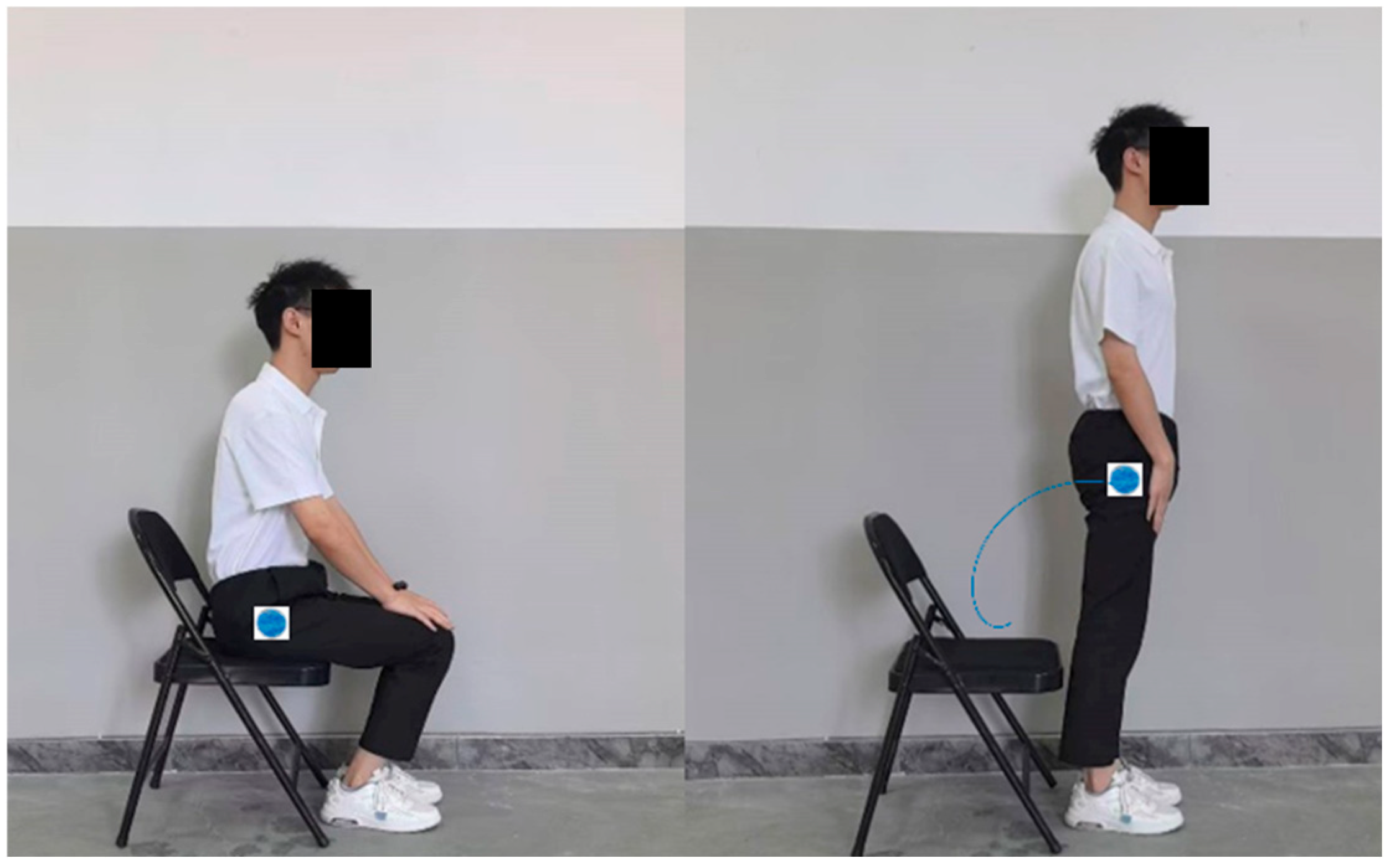
Figure 1. Trajectory of lower-limb hip joint movement.
Machines 13 01059 g001
Figure 2. Definition of the chord angle for an open-loop trajectory.
Machines 13 01059 g002
Figure 3. Flowchart of the searching process.
Machines 13 01059 g003
Figure 4. Schematic diagram of different gear train five-bar mechanisms: (a) fixed-axis, (b) planetary, (c) differential.
Machines 13 01059 g004
Figure 5. Schematic diagram of the gear-five-bar mechanism in the numerical graph library.
Machines 13 01059 g005
Figure 6. FEM model of gear system.
Machines 13 01059 g006
Figure 7. Dynamic analysis process of gear-linkage mechanisms.
Machines 13 01059 g007
Figure 8. The targeted hip joint trajectory of the lower-limb rehabilitation.
Machines 13 01059 g008
Figure 9. Results of different trajectory synthesis.
Machines 13 01059 g009
Figure 10. Mechanical structure diagram of the lower-limb rehabilitation robot.
Machines 13 01059 g010
Figure 11. Three-dimensional mechanical structure diagram of a lower-limb rehabilitation robot developed using Solidworks2021.
Machines 13 01059 g011
Figure 12. The calculated value for potential energy U .
Machines 13 01059 g012
Figure 13. Time-varying mesh stiffness.
Machines 13 01059 g013
Figure 14. Diagram of the gear-five-bar mechanism for the lower-limb rehabilitation robot.
Machines 13 01059 g014
Figure 15. Diagram of the gear-five-bar mechanism for the lower-limb rehabilitation robot with time-varying mesh stiffness.
Machines 13 01059 g015
Figure 16. Fourier series representation of mesh stiffness.
Machines 13 01059 g016
Figure 17. System response under the condition with θ 3 ( 0 ) = 0.001 and θ 3 ( 0 ) = 0 .
Machines 13 01059 g017
Figure 18. Relationship between the maximum vibration amplitude of the system and human body mass.
Machines 13 01059 g018
Figure 19. (a) Virtual prototype and (b) working process of the designed lower-limb rehabilitation robot. (c) Comparison of trajectories from video capture, synthesis, and execution of the virtual prototype.
Machines 13 01059 g019
Figure 20. Demonstration of standing assisted by a lower-limb rehabilitation robot.
Machines 13 01059 g020
Table 1. Comparative analysis of representative lower-limb rehabilitation robots.
Device (Source)TypeDOF
(per Leg)
Adaptability
/Customizability
Key Limitations
Lokomat [1]Treadmill-based Exoskeleton2 (hip, knee)Link length adjustmentVery high cost, large footprint, limited to treadmill walking
LOPES [2,3]Overground Exoskeleton3 (2 hips, 1 knee)-Complex control, accuracy challenges in measurement
Rutgers Ankle [4,5]End-effector (Ankle)6 (on ankle)-Complex control, limited workspace
Single-DOF 6 bar [6]Stationary Trainer1 (system)Fixed design for a specific trajectoryLimited to a single, fixed trajectory
2-DOF Ankle Robot [7]Stationary (Ankle)2 (on ankle)-High stiffness, challenging direction control
RECOVER [9,10]Stationary Exoskeleton2 (hip, knee)Adjustable link lengths and joint axesPrimarily focused on seated training
Proposed RobotStationary Trainer1 (system)Modular links and Re-synthesizable kinematicsLimited to planar sit-to-stand motion
Table 2. Parameters for different trajectory synthesis.
No. l 1
(mm)
l 2
(mm)
l 3
(mm)
l 4
(mm)
l 5
(mm)
α
(rad)
z 1 / z 2 θ 1
(rad)
θ 2
(rad)
ρ
136290341.81902000.369330.31420.31420.9999
22.10960.50791.99561.86553.6134−1.037422.27112.13790.9991
32.01730.59291.70492.16083.3707−1.38932−1.3626−2.42690.9988
44.12510.56866.36045.35904.3497−1.05393−1.0868−2.30580.9985
52.55620.50993.32612.85184.2343−0.384843.1042−2.02870.9981
63.59440.53013.01952.58034.2276−0.289641.76811.09260.9981
Table 3. Specifications for gears.
ParameterPinionGear Wheel
Normal Module M n 33
End Module M t 33
Number of teeth z 1238
Normal pressure angle α n 20°20°
Helix angle β
Addendum coefficient h a 11
Addendum modification coefficient X n 0.47−0.47
Precision grade77
Common normal length W 14.75331.63
Common normal tooth span number k 24
Disclaimer/Publisher’s Note: The statements, opinions and data contained in all publications are solely those of the individual author(s) and contributor(s) and not of MDPI and/or the editor(s). MDPI and/or the editor(s) disclaim responsibility for any injury to people or property resulting from any ideas, methods, instructions or products referred to in the content.