1. Introduction
Manufacturers across industries are implementing robotic automation to improve product quality, increase productivity, and optimize labor costs. In modern manufacturing environments, different types of robots are used for specific tasks [
1,
2]. Some devices are capable of handling hazardous or heavy materials, such as aircraft components or chemicals, while others are designed to perform high-precision operations, such as assembling microscopic computer chips. In addition, there are fully autonomous robotic systems that use sensors and advanced algorithms to navigate the manufacturing environment and transport materials from raw inputs to finished products [
2,
3].
The automation of manufacturing processes is directly linked to Industry 4.0 concepts. Modern approaches enable the integration of CAD (Computer-Aided Design)/CAE (Computer-Aided Engineering) software with robotic simulation platforms [
3]. Siemens NX provides an open programming interface, NXOpen, which enables the automation of design processes. RoboDK is a universal simulation software designed for offline programming of industrial robots. Connecting these systems via Python ver. 3.14.0 scripts creates a flexible solution that is independent of a specific robot or tool, which is key for medium-sized or large engineering companies.
Products made of EPS (Expanded Polystyrene) and EPP (Expanded Polypropylene) are widely used due to their insulating properties and relatively low cost. However, streamlining the production process of EPS/EPP molds requires an analysis of existing approaches to the molding process, mold design, and automation of production processes. This section focuses on the analysis of these areas, specifically the properties of EPS and EPP materials, their production, molding, and the design of molding equipment [
4,
5].
EPS is a type of thermoformable polymer produced by expanding and processing polystyrene. This material is known for its lightness and porous structure, which consists of closed cells. It has several properties that make it popular in various industries [
5].
EPP is a material produced by expanding polypropylene. This material is known for its lightness and high impact resistance. EPP is a versatile material that can be used in various industries, especially where a combination of lightness, impact resistance, and moldability is required [
6].
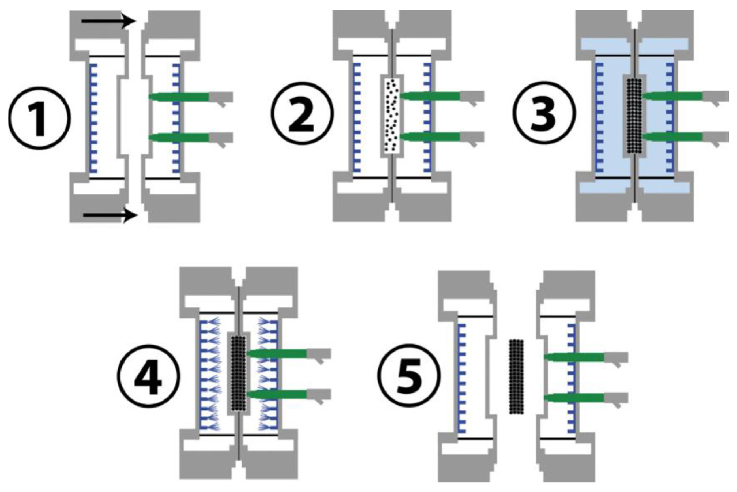
The creation of a finished EPS product involves five steps. The first step is to close the two halves of the mold (1). During the filling of the mold (2), the beads are injected into the closed mold using a Venturi injector. During this phase, it is important to ensure that the beads are evenly distributed. Steam blowing (3) ensures that the pellets expand in the mold. The expansion causes the pellets to bond together by diffusion. Then a vacuum is created in the mold (4) to remove moisture, and the mold with the product is cooled. After cooling, the mold is opened and the product is ejected with compressed air (5) [
5,
6]. The forming cycle is presented in
Figure 1.
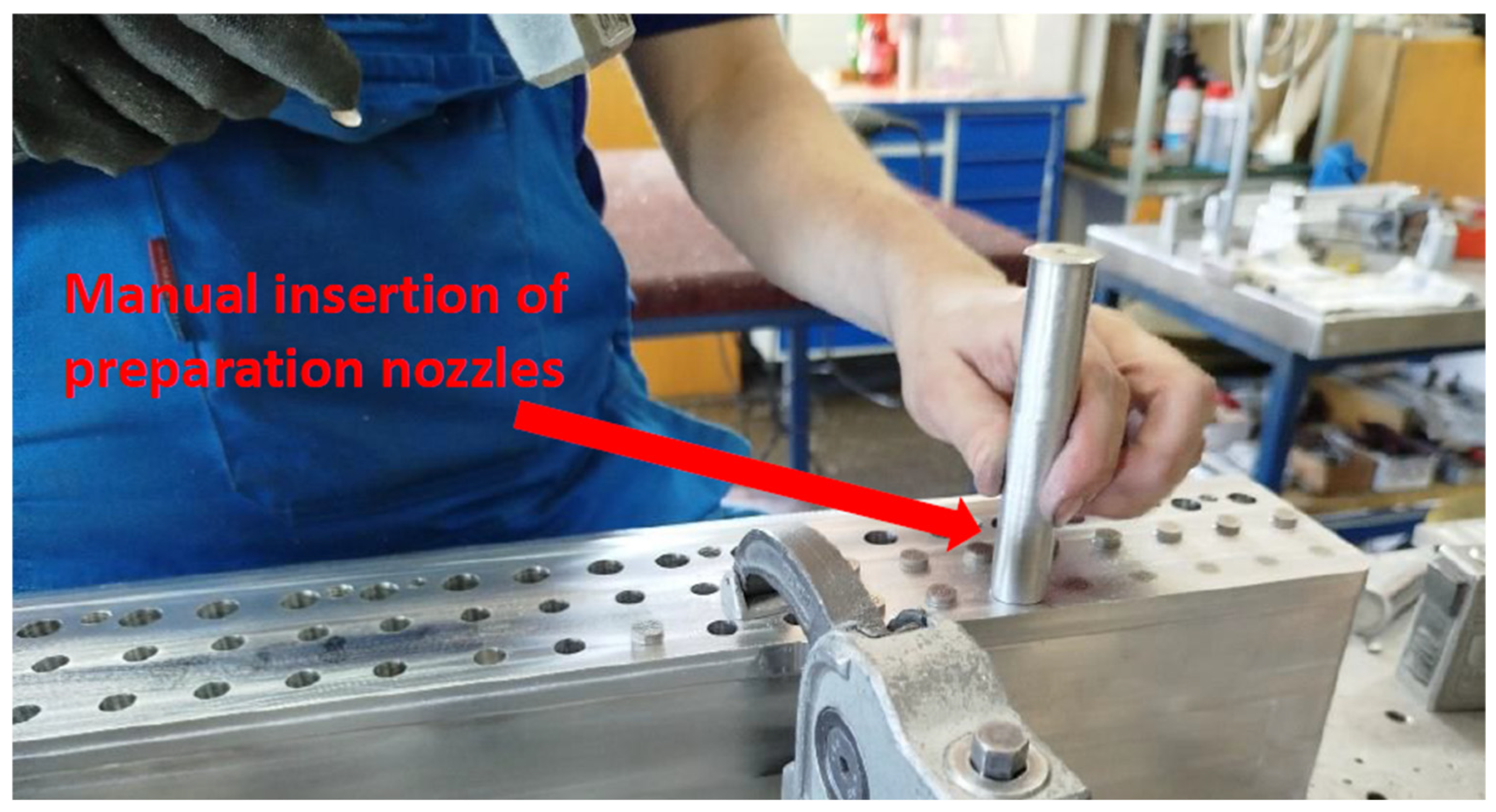
EPS and EPP molds are complex devices consisting of many individual and unified parts. Usually, the mold is divided into two parts—the cavity and the core. Their structural basis consists of three supporting metal panels, most often made of aluminum. The installation of the preparation nozzles is performed manually, with the nozzle being inserted using a transition cylinder and a hammer, as illustrated in
Figure 2. One charge takes approximately 10 to 30 s. Such time frames are due to the influence of the human factor and employee fatigue, as the work is not only monotonous but also requires the use of a heavy hammer, which, in combination with the impact, is physically demanding for humans. The number of nozzles that need to be inserted is 624. Under ideal conditions, one worker would spend approximately 104 to 312 min of monotonous work on one such piece. The aim of this article is to present a software tool that connects the Siemens NX ver. 2506 and RoboDK ver. 5.9 environments and enables the automated generation of robot trajectories for nozzle insertion. The developed application was tested on real CAD models of molds and verified in a simulation environment.
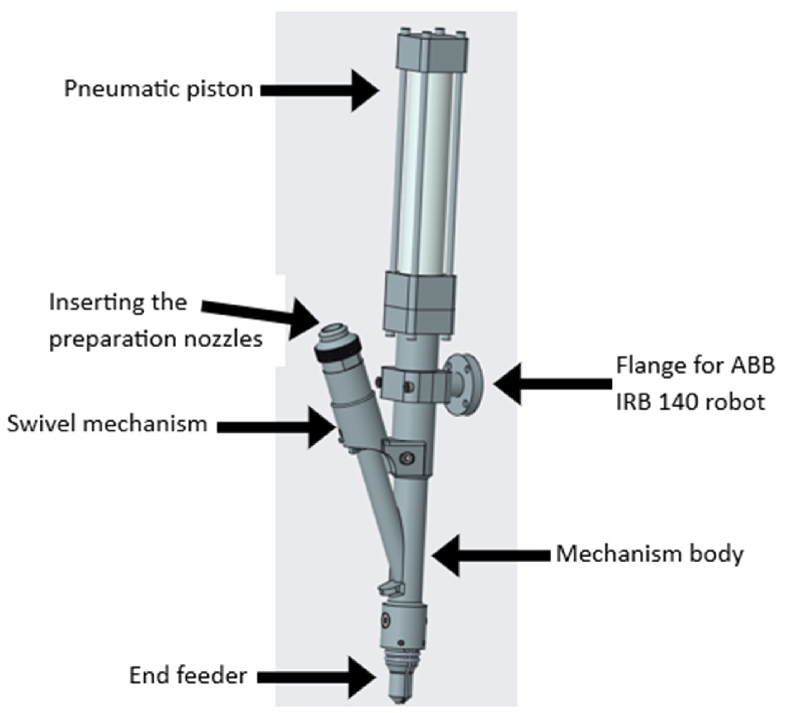
Before the software solution was designed, a prototype inserting device was developed for automation and use in simulation solutions. Development of the device is still ongoing, and testing in real production conditions is required. The device was then clamped as an end effector for the selected ABB IRB 140 robot in the RoboDK software. The mechanism of the designed charging device consists of a pneumatic piston, mechanism body, swivel mechanism, flange, and end feeder. The mechanical design of this device is shown in
Figure 3.
Operating the mechanism consists of three steps. The first is to refill the preparation nozzles in the drum vibrating feeder if there is a shortage. The second task is to visually inspect the mechanism for any faults that could damage the mechanism or the part into which the preparation nozzles are inserted. The third task is to run the program for individual parts. Since each part is often unique, a separate program must be generated for each one.
2. State of the Art
Current developments in industrial automation are closely linked to Industry 4.0 concepts, which are dominated by the integration of digital tools, robotics and artificial intelligence. Modern approaches focus on linking CAD/CAE software with robotic simulation platforms, enabling flexible and rapidly adaptable manufacturing processes [
7]. Research also pays special attention to the robotization of assembly and disassembly tasks, where machine learning, computer vision and multimodal sensors are applied. A significant trend is the development of collaborative solutions that combine human and robot work with an emphasis on safety and ergonomics [
8,
9]. There is also growing demand for open software architectures that enable rapid integration of sensors, visual systems and optimization algorithms. These trends form the basis for the development of adaptive systems suitable for small-batch production with high part variability.
Tzotzis et al. presented a CAD-based application for automated G-code generation for drilling operations without the need for specialized CAM software. The goal was to use the SolidWorks™ ver. 2025 application programming interface (API) to automatically recognize geometric features (holes) in a 3D model, calculate cutting conditions (speed, feed, tool) and subsequently generate G-code according to standard CNC commands. The application was programmed in Visual Basic for Applications (VBA™) and includes a user interface that allows manual or automatic parameter setting according to the workpiece material. The resulting code is exported in TXT or NC format and can be directly used in CNC machines. The proposed solution thus extends the capabilities of CAD systems with basic CAM functions and represents an effective alternative to expensive commercial software. The authors point out the potential of using CAD API not only in code generation, but also in tool path simulation and streamlining production preparation, thereby contributing to the automation and digitalization of machining processes [
10].
An article by Vongbunyong et al. focuses on increasing the flexibility of robotic systems, presenting the concept of cognitive robotics in the field of disassembly. Specifically, these are robotic systems that use learning from previous experiences and the ability to revise strategies, which allows them to adapt to the variability of parts or unforeseen circumstances. Experiments have shown that robots equipped in this way can perform disassembly processes more efficiently, reduce error rates and shorten the time required for individual operations. This approach also highlights the potential for integrating machine learning and adaptive strategies into robotic processes, which are characterized by high variability in industry [
11].
Visual identification of joints is also an important area of robotics research. Mangold et al. developed a system based on a UR5 robotic arm with an integrated camera and YOLOv5 algorithm for detecting screw heads in the remanufacturing process. Their experiments demonstrated the ability to classify six different types of screw heads with an accuracy exceeding 98%. The system proved to be robust even under variable lighting and damaged parts, although there were problems with misclassification of visually similar screws. This research confirms the growing importance of computer vision and neural networks in the automation of disassembly processes [
12].
Collaboration between humans and robots is another key trend in industrial robotics. Ogenyi et al. summarized the latest findings on physical human–robot collaboration (pHRC) in their review. The authors emphasized that effective collaboration requires not only advanced robotic systems, but also interconnection with sensors, actuators and learning algorithms. They place special emphasis on safety, ergonomic aspects and trust between humans and robots, which are essential for the wider application of collaborative solutions in industry [
13].
The problem of coordinating multiple robots was addressed by Yuan et al., who proposed a hybrid task assignment method based on a combination of the K-Means++ and Particle Swarm Optimization algorithms. This method takes into account the capacities of the robots and allows for the efficient distribution of tasks into clusters, which are then optimized in terms of execution order. Experiments in the ROS environment and on real robots confirmed that the proposed approach reduces the total distance traveled and task completion time compared to traditional approaches. The results are particularly significant for applications where multiple robots simultaneously perform complex assembly or disassembly operations [
14].
A special category is represented by works focused on the integration of industrial robots with open software platforms. Diprasetya et al. developed a workflow that enables ABB robotic manipulators to be connected to the ROS system using the OPC UA protocol. This approach allows for flexible control and monitoring of robots, as well as the integration of additional sensors and visual systems directly in the ROS environment. The results show that open architecture significantly increases the modularity and expansion potential of automated cells, while ensuring low latency and robustness in large-scale industrial deployments remains a challenge [
15].
Zheng et al. conducted a study focused on automated robot paths and trajectory planning for the laser welding process of metal parts directly from a CAD model. The goal was to develop a method that can automatically generate a robot path from CAD data without the need for manual programming. The authors started from the topological information of the CAD model (vertices, edges, faces), which they then processed using a binary tree algorithm to remove redundant points and organize the data to create a trajectory. The path was then visualized in the OpenGL environment and verified in simulation experiments on both simple (square) and complex shapes (e.g., a turbine blade). The results showed that the method enables efficient and accurate generation of a robot trajectory based on the STL model, thereby increasing the quality and efficiency of laser welding. The authors also emphasize that different shapes require different trajectory planning algorithms (e.g., contour vs. hyperbolic curves). The experiment represents a significant contribution to the digitalization and automation of additive metal processing processes, as it eliminates dependence on manual robot learning and enables faster connection of the CAD model with the production robotic system [
16].
Wang et al. focused on developing a digital twin-controlled sorting system for a 3D printer farm, integrating printing, sorting, and storage in a single closed digital-physical cycle. They proceeded by combining several technologies: a robotic arm, sensors (RGB-D camera, thermal camera, force sensor), a digital model in Unity3D ver. 6.2, communication via OPC UA, and motion planning algorithms (enhanced RRT-Connect with sampling in ellipsoidal regions). Their system synchronizes physical devices and digital twins in real time with a latency of <50 ms, using force—and temperature-controlled gripping and improved path planning with adaptive sampling. The results showed a 98.7% grasping success rate, a 23.6% reduction in robot path length, and a 191% increase in sorting efficiency compared to manual methods. Limitations include the need for accurate calibration, robustness with variable objects (geometry, temperature), and the complexity of implementing the system in real-world conditions [
17].
Onstein et al. focused on the creation of additive manufacturing (AM) paths using robotic manipulators based on CAD models. The aim of the study was to use a six-axis robot for additive material extrusion technology, thereby expanding the workspace and removing the limitations of traditional layered printing. The authors developed a method that generates paths directly from simple surfaces of CAD models—the surface is first sampled into a point cloud, from which the robot path is then created. They tested three approaches to path generation, with the best results provided by the weighted greedy choice algorithm, which allowed for smooth nozzle guidance on curved and nonlinear surfaces. The results showed that the use of a 6 DOF robot significantly increases the flexibility of the process, reduces the need for support structures and enables the additive production of complex shapes on a larger scale. The authors emphasize that the connection of CAD modeling with robotic path generation represents an important step towards robot-assisted additive manufacturing and opens up new possibilities in the field of large-scale AM [
18].
3. Materials and Methods
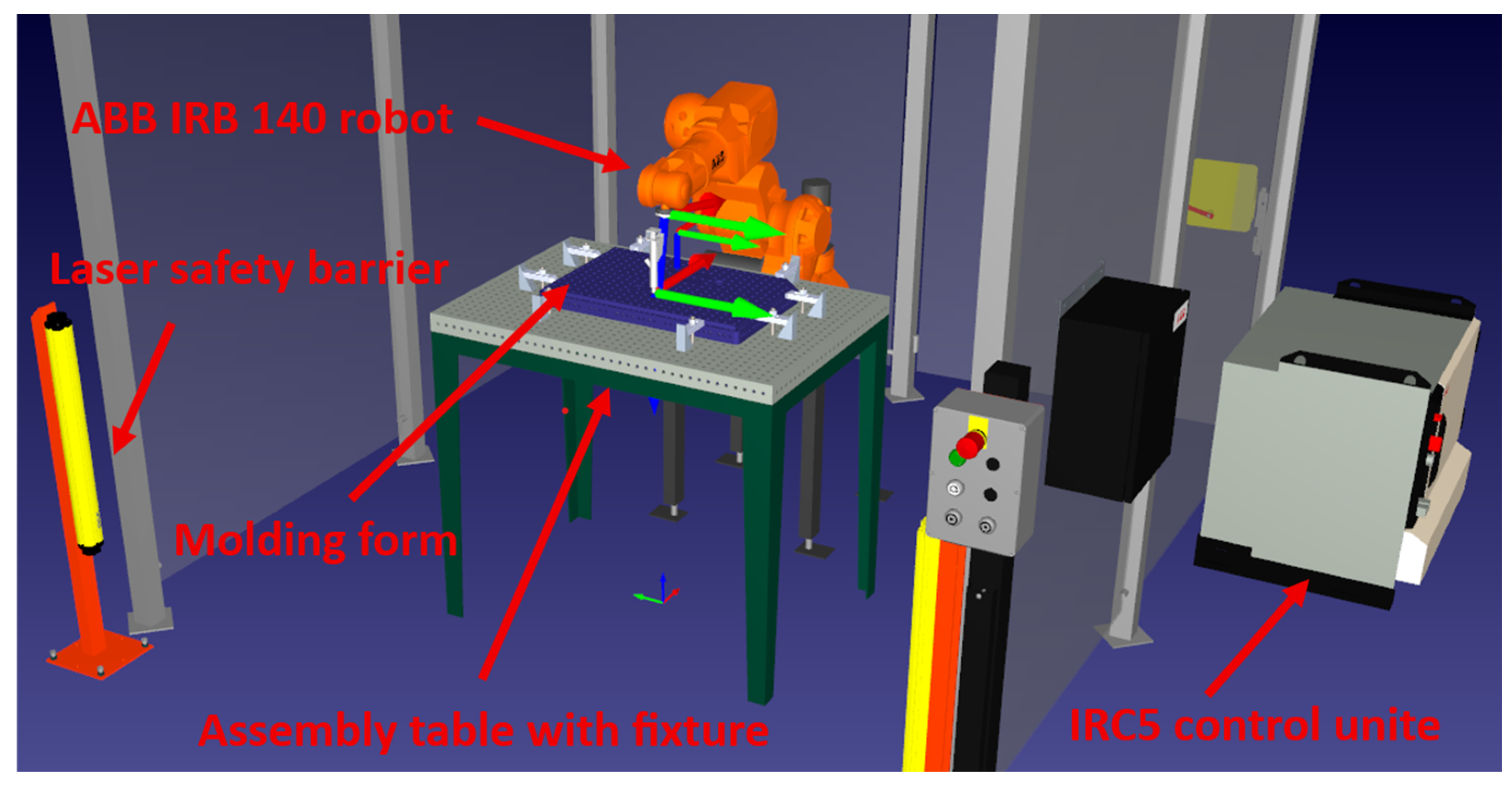
This section describes the overall system architecture, hardware configuration, and software methodology used in the proposed solution. The robotic arm chosen for this simulation design is an ABB IRB 140 industrial robot, a six-axis articulated manipulator with a payload of 6 kg and a reach of 810 mm. This robot was chosen due to its widespread use in assembly applications, its compact design suitable for confined workspaces, its compatibility with the RoboDK software, and the company’s availability of the robot. The complete system integrates three main components: (1) Siemens NX for mold design and hole detection, (2) Python-based middleware using the NXOpen and RoboDK API libraries for data transfer and processing, and (3) RoboDK simulation environment for robot trajectory generation and validation. The workflow is as follows: CAD model analysis in Siemens NX; hole detection and data extraction using a Python script; trajectory generation in RoboDK software; simulation validation; program export in a robot-specific format. This modular architecture ensures that the system can be adapted to different robot brands and models without requiring major changes to the core algorithm. The proposed workplace is shown in
Figure 4.
The main idea behind the solution is to use data from the CAD model to automatically generate robot trajectories in a simulation environment.
Siemens NX was chosen as the CAD software for this purpose, as it is CAD/CAE software used by a large number of manufacturing companies. Another advantage of choosing this software is its open API, which allows access to the active session and retrieval of data about the current CAD model. The NXOpen library was chosen as the tool for working with the NX API. Its advantage is the wide range of possibilities for intervention in Siemens NX, which requires a high level of knowledge of OOP (Object-Oriented Programming). RoboDK software was chosen for working with robot simulations and programming their trajectories. This choice was made based on features such as its simple interface and versatility, i.e., the ability to work with different robots and export programs in their native format. However, the main advantage is the availability of a well-documented and easy-to-learn API. The bridge between the two APIs is a script written in one of the supported programming languages. The selected applications support a similar set of programming languages. Common languages include Python, C, C++, C#, and Visual Basic (.NET). Python was selected from among these. Its advantages are simple syntax, dynamic memory types, and fast program prototyping. Since it is an interpreted language, it requires the installation of an interpreter, which is available on most platforms. The chosen approach requires more time to execute scripts compared to compiled languages such as C, C++, and C#.
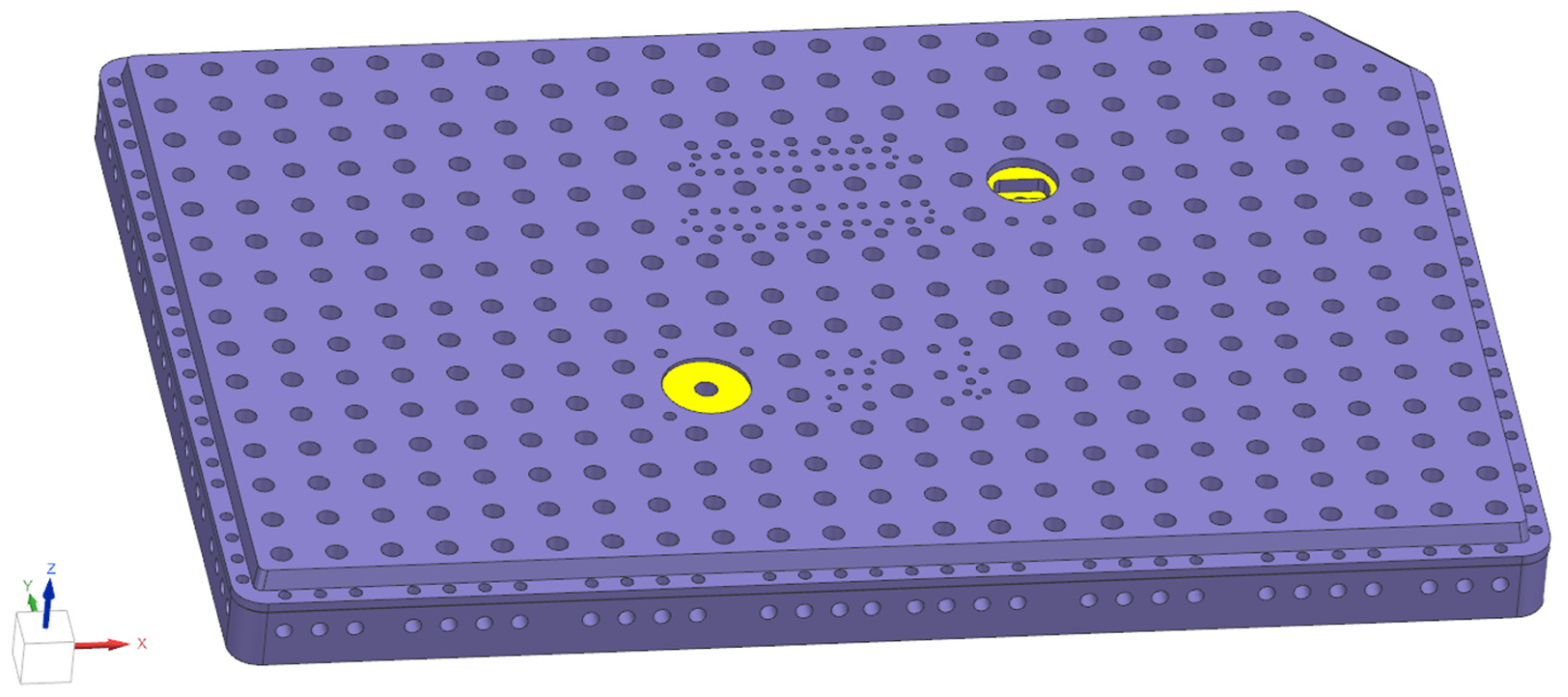
When creating an API between Siemens NX and RoboDK software for transferring model information, it is necessary to understand the object structure of the CAD core model. A type A core model was selected for evaluation (see
Figure 5). The object tree of this model contains various holes, sketches, and threads. Among them, the holes intended for nozzles are significant, specifically through holes with diameters of Ø 8, 7.8, and 5.8 mm. There are 9 objects in this tree: 1 × 9.8 mm, 5 × 7.8 mm, and 3 × 5.8 mm. After selecting the object with a diameter of 9.8, the molding form contains approximately 300 holes.
For the interaction between Siemens NX, Python, and RoboDK software, it is necessary to start with the Siemens NX, as external API scripts must be executed through the built-in Journal mechanism in developer mode. By default, NX uses a local Python interpreter with limited library support. To enable integration with external libraries such as the RoboDK API, the NX configuration file (ugii_env.dat) must be modified to point to an external Python interpreter. This is achieved by editing environment variables to specify the path to the external Python installation and its associated libraries. The configuration process is platform-independent and follows standard procedures documented in the NX customization guide. Once configured, the system can utilize third-party Python libraries, although certain restrictions apply to libraries that rely on multithreaded processing (e.g., NumPy) due to NX implementation specifics.
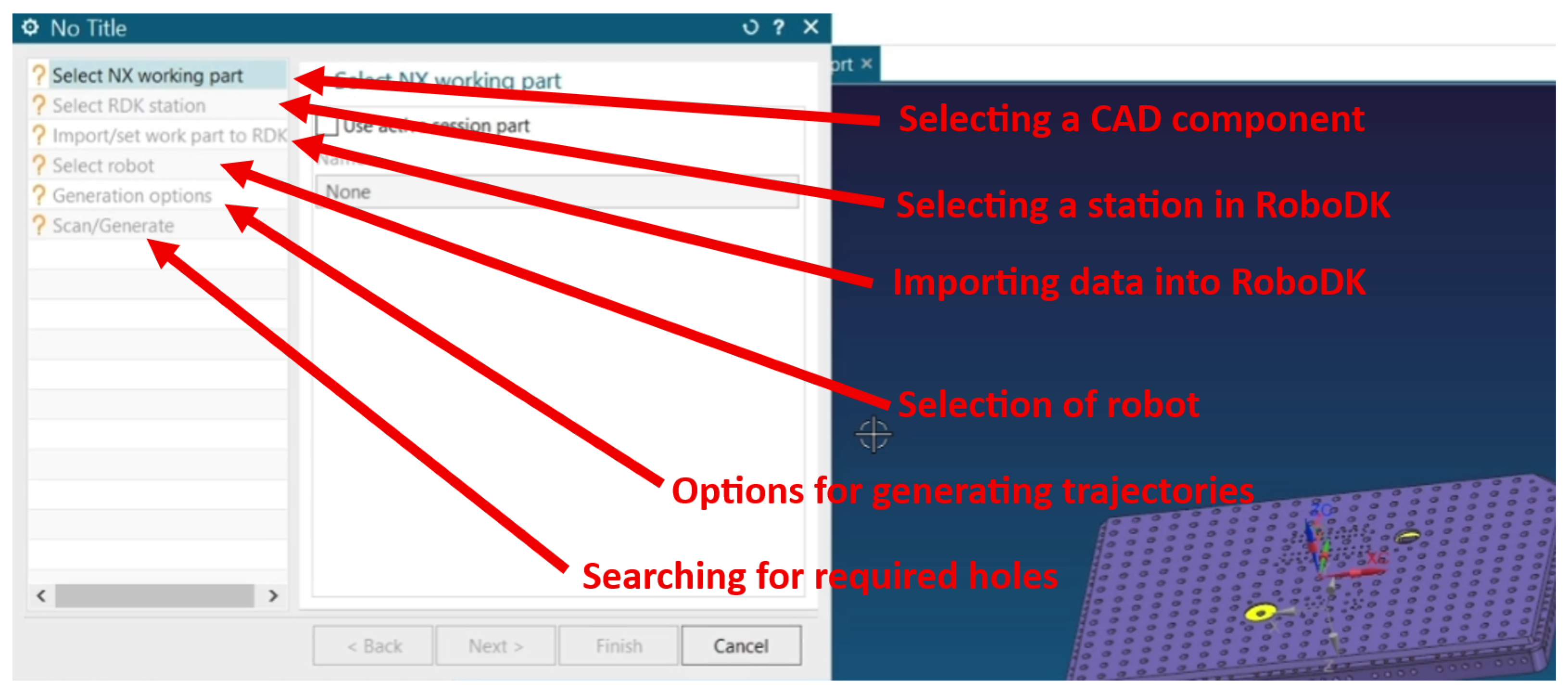
The user interface is an integral part of any software tool. A well-designed interface optimizes user interaction with the application and provides faster task processing. The final user interface design of the developed application is presented in
Figure 6. The key to success is convenience, intuitive operation as well as informative and valid feedback. To create the user interface, the most affordable option is to use Siemens NX’s dialog creation tool, Block UI Styler, and the Tkinter library. Block UI Styler is designed to create NX-style dialogs and contains collections of ready-made widgets. In this respect, it is similar to the popular OOP-structured interface designers. However, due to its NX style, it has limited functionality compared to its analogs. This relates to the inability to set a constant window size or align elements.
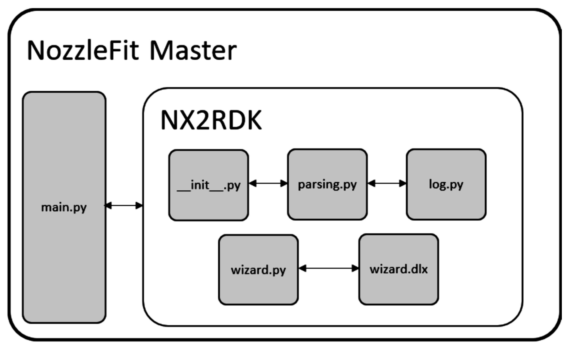
Code structuring is an essential procedure when writing programs with multiple functions and classes. The structure of the created application consists of the NX2RDK Python package and the main.py module, as illustrated in the structural diagram in
Figure 7. The main module acts as a startup script that executes and combines the variables, functions, and classes available in the NX2RDK package. Which in turn consists of modules:
__init__.py—in addition to the above task, contains a description of all global variables and settings, including the location of the dialog box files;
parsing.py—contains functions and classes for parsing CAD models and generating trajectories;
log.py—a set of functions for easier logging and debugging;
wizard.py—a dialog box module that contains its class and functions. It is automatically generated using the Block UI Styler tool. Placement in the package is not mandatory, as it is only called from the main module. However, in this case it is advisable to;
wizard.dlx—the dialog box graphics file. It is automatically generated by the Block UI Styler tool. It must be located at the same level as its module.
Module main.py: This module initializes the NX2RDK libraries and package, makes connections to the API, and most importantly, handles the dialog behavior defined in the wizard.py and wizard.dlx modules. Due to the above and as mentioned before, they are automatically generated and therefore not recommended to use during development. As a solution to this problem, the capabilities of Python as a dynamic language were used, namely overriding and extending methods and functions of an already defined class. In addition, the module also contains the export () and rdk_start () functions, which are responsible for exporting the model from Siemens NX to RoboDK and for starting RoboDK.
Module parsing.py: This module is a direct inheritor of the prototype with some improvements. Like the prototype script, it contains the HP class. Objects of this class represent a series of holes of the type HOLE PACKAGE and contain the necessary information and functions to process them.
Testing of the Proposed Software Solution
This section presents a comprehensive series of simulation tests designed to validate the functionality, optimization capabilities, and limitations of the proposed software solution. The testing methodology employs a real industrial CAD model of an EPS/EPP mold (Type A core model) containing 322 holes with diameters of 9.8 mm, 7.8 mm, and 5.8 mm. All tests were conducted in the RoboDK software using an ABB IRB 140 robot.
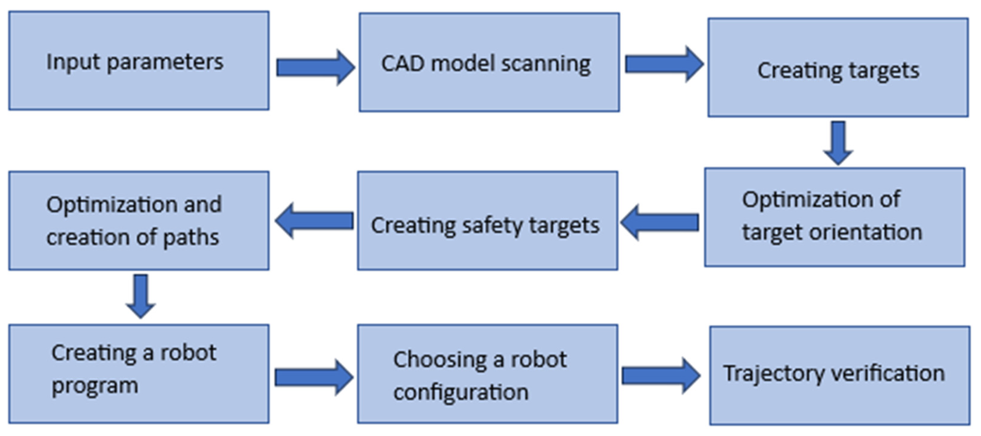
The software concept includes key functions such as user interaction, information processing, and robot trajectory generation based on that information. The general phases of the software solution are shown in
Figure 8. The program accepts workpiece model files and RoboDK stations, information about the robot and its tools as input data. Other input parameters include generation settings, selection of a series of target holes, correction values, and safe zone distances. Once generation is started, targets are created in RoboDK from the acquired hole data and undergo several stages of optimization and verification. The main optimization goals are the orientation of the targets relative to the robot and the sequence of hole processing. The final result is a generated trajectory in the form of a program in RoboDK.
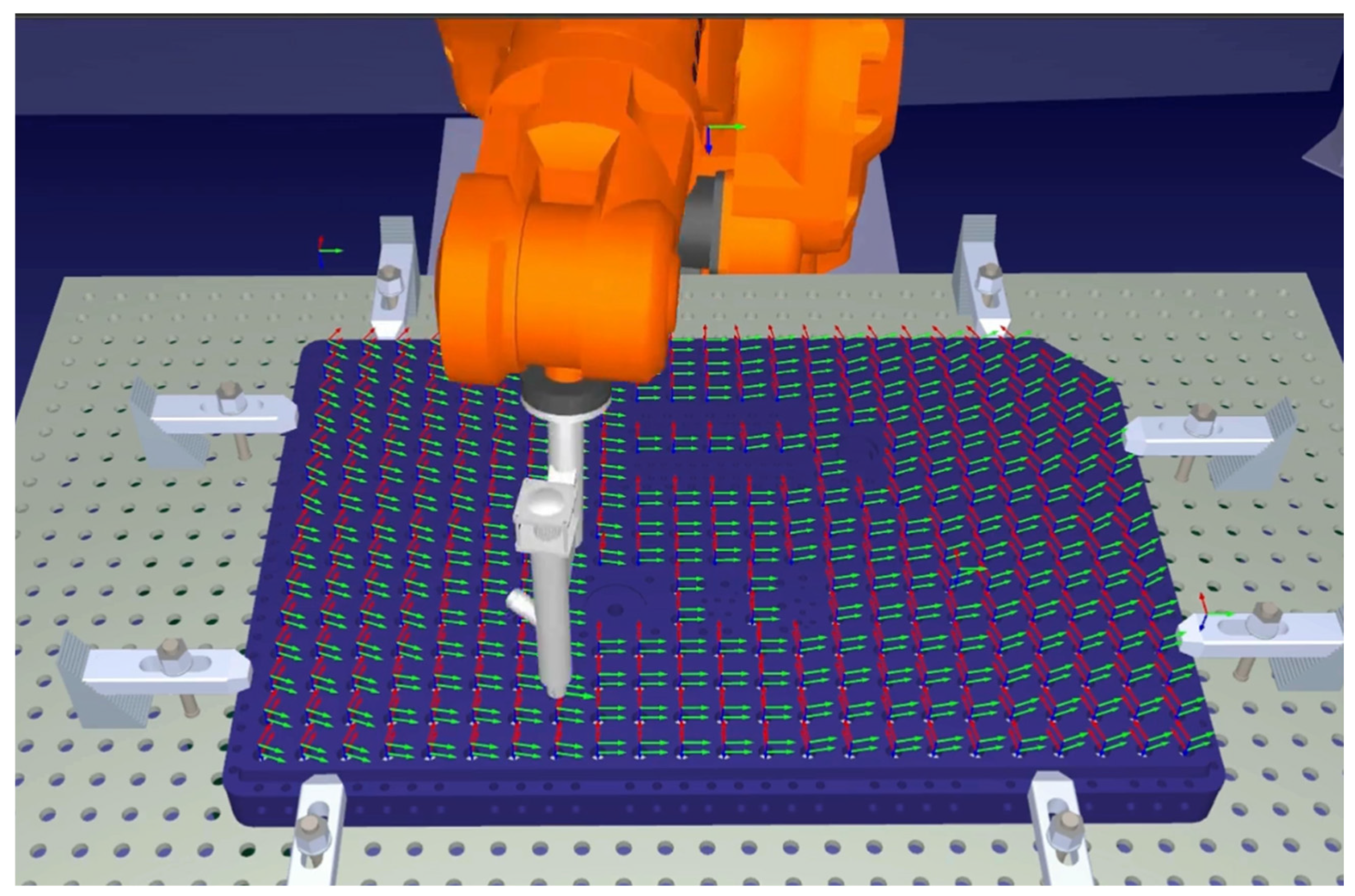
The purpose of the tests is to gradually demonstrate the configuration options and their impact on the application response. The aim of the first test (
Figure 9) was to demonstrate the optimization of target orientation in terms of the smallest possible movement of the robot joints from the zero position. For this purpose, the “Only targets” mode was used and no safety distance was specified, which excludes the creation of safe targets. The result of target generation is the alignment of the X axes of the targets towards the robot, which clearly demonstrates the functioning of this optimization. Data transfer took 41 s for 322 holes, which means ≈0.129 s per hole. The measurement of the generation time is subjective, as it may vary depending on the computing power of the computer.
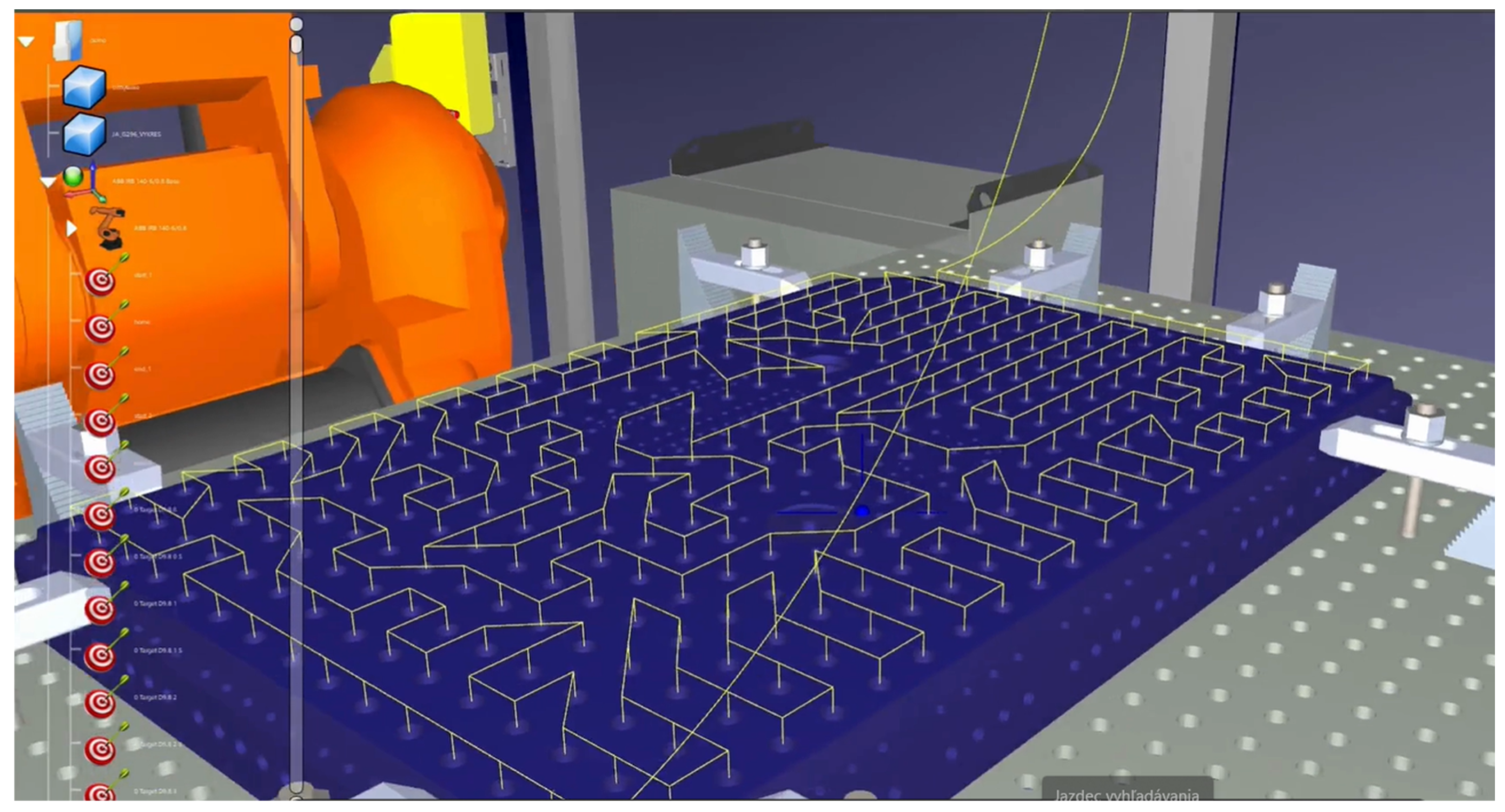
The following test demonstrates trajectory generation without optimization. A visual inspection of
Figure 10 shows that the trajectory has an arrangement in which the trajectory starts from the edge of the workpiece and moves towards the robot and then returns to the start for a new column. This arrangement is caused by the principle by which the Siemens NX algorithm works to place the hole matrix. In some areas, it makes inconsistent jumps between holes.
The program report also shows the algorithm for adding movement instructions to the robot program. The script first informs the user that it is not possible to move linearly from the initial target to the safe target of the first hole and from the safe target of the last hole to the final target, as shown in
Figure 11.
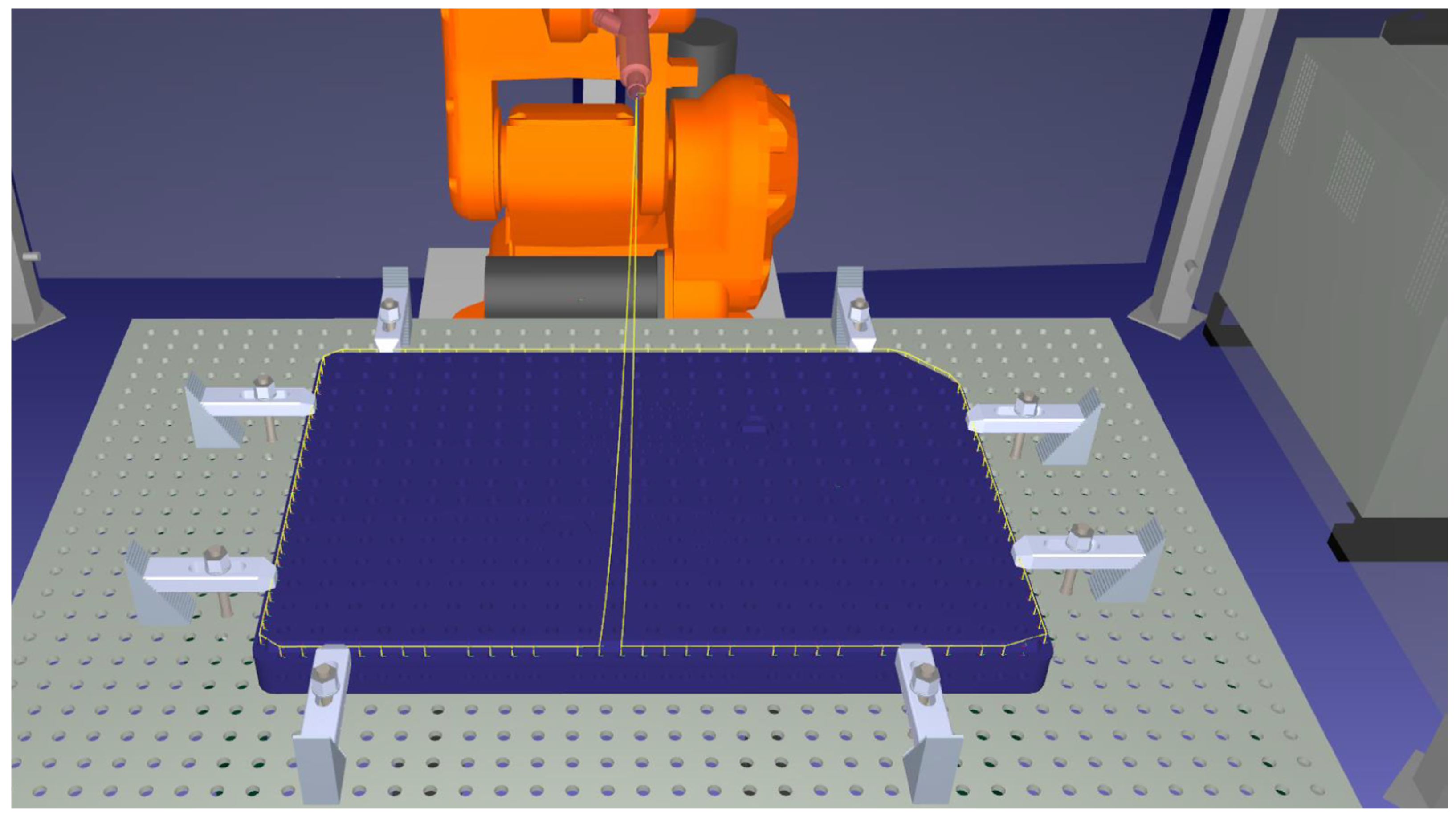
Instead, it adds an articulated motion. These instructions are then replaced by linear and articulated motions again, confirming the previous conclusion of the algorithm, and the result is the approval of the articulated motion instructions. Unlike the previous test, the third test has trajectory optimization enabled, but without the random factor. The initial and final targets remain the home position target. The result of the optimization is shown in
Figure 12. It is clear from this that the trajectory has become a closed curve without intersections.
As in the previous test, the movement from the home target to it is the same as for the initial and final targets of the hole. The main difference is the total length of the trajectory and the time taken to complete it ≈23 m 19 min and 16 m 13 min for tests without optimization and with optimization. The result is a ≈30% reduction in path length and a ≈32% reduction in time. In the next simulation, the random mixing parameter was enabled. The result in
Figure 13 shows the change in the initial openings—they are now close to the home target. This confirms the principle of the optimization algorithm with a random factor—the initial and final openings are selected as closest to the initial and final targets, respectively. There was also a reduction in path length of ≈2%.
This approach allows for optimal trajectory generation in terms of determining the entry and exit points of the trajectory based on the test results. In this approach, the start and end targets are located on opposite sides of the part. In addition, three subroutines have been included in the robot program:
move instructions—„Prog1”;
save move instructions—„Prog2”;
on-hole instructions—„Prog3”.
“Prog1” is responsible for moving to/from safe targets from start/end targets and between safe targets. It contains a command to set the speed to 100 mm/s. “Prog2” contains commands that are executed when moving between a safe target and a target with a single hole. In this case, it sets the speed to 10 mm/s.
The final test was specifically designed to verify the functionality of the collision detection system under challenging geometric conditions. For this purpose, a problematic series of holes was deliberately selected—holes whose location cannot be achieved with a conventional tool due to geometric constraints and dimensional limitations of the insertion device. This test scenario represents the worst possible condition in which collisions are expected to occur, allowing verification that the detection algorithms work correctly.
The result was the trajectory shown in
Figure 14, and as expected, the program successfully detected and reported the first collision occurrence at the beginning of the trajectory via console output. Visual inspection of the generated trajectory confirmed that the path indeed intersected the workpiece geometry at multiple locations, verifying the accuracy of the collision detection algorithm. In addition, the robot correctly identified several target holes as unreachable due to kinematic and workspace constraints, demonstrating that the system correctly recognizes the boundaries of physical feasibility.
4. Results and Discussion
The quantitative comparison between manual and automated assembly reveals substantial efficiency improvements and demonstrates the practical value of the proposed solution. Currently, manual insertion of preparation nozzles requires approximately 10 to 30 s per piece, with significant variability due to worker fatigue and the physically demanding nature of repetitive hammer impacts. For a typical mold containing 624 nozzles, this translates to 104 to 312 min (1.7 to 5.2 h) of monotonous work per mold under ideal conditions. In contrast, the simulation results demonstrate that the automated system processes 322 holes in 41 s for data transfer and target pose creation, equivalent to 0.129 s per hole.
Trajectory generation phase:
Data transfer from Siemens NX + target pose creation: 41 s for 322 holes (0.129 s/hole)
Trajectory optimization computation: additional time (<5 s)
Total offline preparation time: ~46 s
Robot execution phase (simulation):
Optimized trajectory execution: 13 min for 322 holes (~2.4 s/hole including approach, insertion motion, and retraction)
Non-optimized trajectory execution: 19 min for 322 holes (~3.5 s/hole)
Therefore, the total automated cycle time—including both trajectory generation and robot execution—would be approximately 26 min compared to the 104–312 min required for manual assembly. This represents a potential time reduction of 75–92%, while simultaneously eliminating worker fatigue, reducing occupational injury risk from repetitive hammer use, and ensuring consistent insertion quality across all nozzles.
The simulation results clearly confirmed that the proposed software tool can effectively support the process of automated assembly of preparation nozzles into molds for EPS and EPP polymers. The achieved optimization results demonstrate a 30% reduction in path length and a 32% reduction in execution time (from 19 min to 13 min) when comparing the unoptimized trajectory (following the native CAD hole sequence) with the optimized trajectory using the nearest-neighbor heuristic with random start point selection. The key benefit of the solution is the reduction in the time required to process a large number of holes, which is in line with trends reported in the literature, which emphasize the growing need to reduce manual labor in favor of robotization. Compared to the manual process, which is time-consuming and dependent on the physical capacity of the worker, the automated approach eliminates fatigue, reduces errors and increases the overall consistency of results.
The proposed solution corresponds to the current trends in the field of cognitive robotics and adaptive systems that have been presented in the literature. Similarly to the work of Vongbunyong et al., which deals with increasing the flexibility of robotic systems through learning from previous experiences, our solution provides adaptability for part variability. Unlike specialized systems for specific tasks, the proposed tool provides a universal platform applicable to different types of assembly operations.
At the same time, however, it was found that the system has certain limitations. The most significant limitation is collision resolution—for more complex geometries or more complicated hole layouts, the designed algorithm needs to be modified according to the actual requirements of companies. This finding indicates the need for further research in the field of intelligent trajectory planning, heuristic methods, genetic algorithms or various sensor systems can be used, for example.
The current limitations stem from the architecture of the Siemens NX API, which does not allow full use of multi-threaded processing. This fact is also confirmed by the experience of other authors who point out the limitations of closed APIs when integrating with external systems.
A comparison with current approaches in the literature shows that the greatest advantage of the presented solution is its flexibility and independence from a specific type of robot or tool. This is a shift towards practical applicability in small-batch production, where the variability of production tasks is high and traditional solutions often encounter low adaptability. At the same time, it should be emphasized that practical implementation requires the addition of more robust motion control mechanisms and more complex testing on real physical devices, not just in a simulation environment
5. Conclusions
This article deals with the design, testing, and implementation options for a software solution for the automated assembly of preparation nozzles into molds intended for the production of products from EPS and EPP materials. The current assembly of preparation nozzles is performed manually, which is a time-consuming and physically demanding task. The issue was addressed by integrating Siemens NX with the RoboDK software using the Python programming language and the NXOpen and RoboDK APIs.
Testing in a simulation environment confirmed the algorithm’s ability to automatically detect the positions of the holes intended for the steaming nozzles and to generate optimized robot trajectories based on this data. Simulation tests on real CAD mold models demonstrated the functionality of the proposed approach in processing 322 holes in a time of 41 s, or 0.129 s per hole. These results form the basis for potential implementation in real production conditions.
The results of simulation tests confirmed that the proposed algorithm and its implementation can significantly reduce time and optimize the robot’s path. Specifically, the optimization algorithms contributed to a reduction in path length of approximately 30% and a reduction in trajectory execution time of more than 30%. In practice, this means that while a manual worker needs several hours for assembly, the robot can process the same number of holes in a matter of minutes, eliminating fatigue, monotonous work, and the risk of injury. These results are in line with trends in industrial automation, where the integration of digital tools leads to increased productivity, improved production quality, and overall process efficiency.
Despite the results achieved in the simulation environment, several limitations should be noted. The most significant limitation is that the proposed solution has been verified exclusively in a virtual environment, where based on the results obtained, it is possible to conclude that there are significant time savings and safer working conditions for employees. To assess critical operating indicators, such as (1) the success rate of nozzle insertion on the first attempt, (2) actual cycle time per nozzle including mechanical insertion, (3) failure rate due to misalignment or jamming, and (4) potential damage rate to molds or nozzles during automated assembly, physical validation on an actual ABB IRB 140 robot is required. These parameters are essential to confirm the practical viability of the system in industrial production conditions.
Overall, it is possible to conclude that the proposed solution brings real benefits to small-batch production, where component variability and frequent configuration changes make manual work inefficient. The flexibility, versatility, and openness of the software design confirm that the integration of CAD/CAE systems with robotic simulation platforms is a promising tool for increasing productivity and quality in mold manufacturing, as well as in the broader context of industrial automation.
Future research directions include the following: (1) physical testing and validation on industrial robots to quantify real-world performance metrics, (2) implementation of advanced collision detection and avoidance algorithms for complex geometries, (3) integration of force and vision sensors for adaptive real-time control, (4) parallelization of computational processes to further reduce trajectory generation time, (5) enhancement of the user interface for improved operator experience, and (6) extension of the system functionality to other assembly and material handling tasks beyond nozzle insertion.
