Article

Design Optimization of Sensor-Embedded Bearing Rings in Heavy-Duty Electric Shovel Applications via Multi-Physics Coupling Analysis and Experimental Validation

1
College of Mechanical and Vehicle Engineering, Changsha University of Science and Technology, Changsha 410114, China
2
Hunan Provincial Key Laboratory of High-Performance Intelligent Manufacturing Key Technologies for Mechanical Equipment, Changsha 410114, China
*
Author to whom correspondence should be addressed.
Machines 2025, 13(11), 1008; https://doi.org/10.3390/machines13111008
Submission received: 17 September 2025 / Revised: 25 October 2025 / Accepted: 29 October 2025 / Published: 1 November 2025
(This article belongs to the Section Machine Design and Theory)

Abstract

To enhance the thermo-mechanical coupling performance of heavy-duty bearings with smart sensing capability in electric shovel applications, this study proposes a multi-objective optimization methodology for sensor-embedded bearing rings incorporating smart sensor-embedded grooves. Driven by multi-physics coupling analysis and experimental validation, a coupled thermal–mechanical model integrating frictional heat generation, heat transfer, and stress response was established. Parametric finite element simulations were conducted, with varying groove depths and axial positions. A comprehensive performance index combining three metrics—maximum temperature, equivalent stress, and principal strain—was formulated to evaluate design efficacy. Experimental tests on thermal and strain responses were employed to validate the simulation model confirming its predictive ability. Among the 21 parameter combinations, the configuration featuring an 8 mm groove depth located 20 mm from the large end face exhibited relatively optimal synergy across thermal dissipation, structural strength, and strain sensitivity. The proposed framework provides a certain theoretical and practical guidance for the design and optimization of the sensor-embedded groove structure in intelligent heavy-duty bearings.

1. Introduction

Mineral resources are pivotal to national economic development and strategic security [1]. As a crucial component in open-pit mining equipment, electric shovels are rapidly evolving towards intelligent and digital systems to improve operational efficiency and ensure safety [2,3,4]. The bearing is subject to prolonged exposure to high loads and low-speed, heavy-duty conditions, rendering it highly susceptible to failure. The bearing has become a key limiting factor in the reliability and service life of electric shovels [5,6,7]. Consequently, improving both the structural design and condition-monitoring capabilities of such bearings is essential for the safe operation of intelligent mining equipment [8,9,10,11].
In addition to structural and operational factors, the manufacturing quality of bearing rings plays a crucial role in determining their long-term performance. The surface waviness, residual stress distribution, and dimensional accuracy inherited from the production process directly affect the stress state and fatigue life of the rings. Zmarzly [12] analyzed the technological heredity in the production of AISI 52100 steel bearing rings, demonstrating that machining-induced waviness significantly influences the contact behavior and service reliability. These findings highlight the importance of considering manufacturing effects when assessing the thermo-mechanical performance of bearing structures. Wang et al. [13] established a thermomechanical coupling model for axle-box bearings under track irregularity excitation and analyzed their temperature characteristics, providing an important reference for bearing thermal behavior.
With growing demands for mechanical system reliability, rolling bearings are expected to exhibit improved thermal stability and enhanced fault-detection capabilities. During operation, considerable heat is generated, giving rise to complex thermal stresses, lubricant degradation, and material ageing—challenges that traditional thermal control strategies often fail to address. This has prompted the development of thermo-mechanical coupling models that integrate multi-source data for enhanced predictive accuracy [14,15]. In order to obtain the physical parameters that reflect the operating status of the bearings and feed them back into the design process. In this context, embedding sensors within the bearing structure has become a focal point in intelligent bearing development.
Russell et al. [16] embedded thin-film stress sensors into the inner surface of bearing rings to noninvasively measure actual bearing loads, providing foundational data for structural design and service life prediction. Alian et al. [17] embedded Fiber Bragg Grating sensors into bearing assemblies to achieve high-precision load and defect monitoring, which proved effective even in complex lubrication environments. Wang et al. [18] developed a recessed thin-film sensor with an embedded structure, enabling online multi-dimensional parameter monitoring via multi-channel data transmission. Moving beyond conventional external sensing schemes [16,17,18], Shao et al. [19] introduced an embedded multi-parameter compound sensor housed in a slotted outer ring to construct an integrated sensing system. This system captures vibration, temperature, and rotational speed data to enable comprehensive bearing fault identification and diagnosis. Zhang et al. [20] conducted finite element analysis of the effects of radial slotting on the outer ring and developed an embedded vibration monitoring system. Their experiments confirmed that the proposed structure enhances signal sensitivity without compromising bearing life, providing valuable insight for the integrated design of intelligent bearings.
In recent years, design optimization of rotor-bearing systems has received increasing attention, focusing on enhancing dynamic performance, reliability, and thermal–mechanical coupling characteristics. For example, multi-objective optimization approaches integrating bearing geometry, material heterogeneity, and lubrication performance have been employed to improve load-carrying capacity and minimize vibration response [21]. Furthermore, recent studies have incorporated reliability-based design and probabilistic modeling to ensure system robustness under varying operational conditions [22]. These advances provide valuable insights for the optimization of sensor-embedded bearing rings in complex rotor-bearing systems.
Thermo-mechanical coupling, as a representative multi-physics modeling technique, is gradually replacing traditional single-variable simulations, offering enhanced accuracy in capturing the interactive behavior of thermal and mechanical responses. Recent studies have increasingly adopted integrated models under the combined action of temperature and mechanical loads to better characterize heat distribution and local structural evolution.
Xiao et al. [23] employed principal component analysis to extract dominant thermal and deformation features, enhancing data efficiency in sensor systems. To mitigate thermal deformation in high-temperature conditions, Bhat et al. [24] proposed thrust bearings with embedded cooling circuits and validated their design using CFD and structural simulations. However, this strategy focuses on fluid-film bearings and does not address thermo-mechanical effects of sensor-embedded grooves in rolling bearings under heavy-load conditions. Luan et al. [25] introduced groove structures in lubricant channels to optimise flow distribution and reduce local overheating. The Reynolds equation and third-kind boundary conditions are used in modeling flow–thermal–structural coupling in grooved domains. Brito et al [26,27] further improved thermal diffusion in high-temperature environments by implementing twin-groove designs, significantly enhancing bearing lifespan and energy efficiency.
In long-term service conditions, the thermo-mechanical coupling behavior of bearing systems becomes a critical factor in performance degradation and failure. The interplay of lubricant degradation, frictional heating, and structural deformation leads to rapid internal temperature rises and fluctuating stress states, which accelerate material fatigue and structural damage [28,29,30,31]. Su et al. [32] proposed an improved spindle model based on the thermal network method to enhance temperature rise prediction under high-temperature conditions. Zhan et al. [33] introduced a convolutional neural network surrogate model for iteratively updating thermal network simulations, balancing accuracy and computational cost. Based on the thermal network method, Gao et al. [34] the transient temperature balance equation of the electric spindle, revealing the time-varying characteristics of contact resistance and load paths.
In the field of railway transportation, Wang et al. [35] developed a thermo-mechanical coupling model for double-row tapered roller bearings under grease lubrication, resulting in a heat stress analysis model suitable for high-speed train condition monitoring. Zhao et al. [36] built a thermo-mechanical coupling model for FAG axle box bearings driven by load distribution and optimised the roller crowning profile to improve temperature uniformity and load adaptability. Zhang et al. [37] studied the influence of different roller materials on thermal conductivity and explored the coupling mechanism between elastic contact and thermal deformation under high-speed conditions. An [38] constructed a 3D finite element model incorporating temperature fields, thermal deformation, and contact loads for angular contact ball bearings, conducting detailed sensitivity analysis. Song et al. [39] developed a multi-physics coupling test platform and proposed a feature fusion strategy integrating vibration, temperature, and speed signals, improving the accuracy and timeliness of intelligent perception.
This study aims to address the challenges of complex thermo-mechanical coupling and high sensing requirements in heavy-duty electric shovel bearings. A comprehensive multi-physics coupling framework is established to analyze the temperature, stress, and deformation responses of sensor-embedded rings used in the smart bearing, integrating both numerical simulation and experimental validation. The main innovation of this work lies in coupling structural heterogeneity with multi-physics field analysis to reveal the influence of groove parameters on the bearing’s thermo-mechanical behavior. Furthermore, a multi-objective optimization strategy is proposed to determine the optimal groove configuration, providing theoretical guidance and engineering reference for the design of intelligent heavy-duty bearings.

2. Theoretical Modeling Framework

To accurately capture the thermo-mechanical behavior of heavy-duty electric shovel bearings under complex service conditions, a multi-physics modeling framework is developed. This framework consists of six interdependent submodules: a contact load model, a contact stress model [40], a heat generation model, a heat transfer model, a thermo-mechanical coupling model, and a groove geometry modeling module. Together, these modules provide the theoretical basis for subsequent finite element simulation and structural optimization.

2.1. Heat Generation Formula

The frictional torque generated during bearing operation mainly consists of two components: one is rolling friction induced by the applied load, and the other is viscous friction resulting from lubricant shear. The total frictional torque M t can be expressed as:
M t = 160 × 10 7 f 0 d m 3   +   f 1 P 1 d m ,          v n < 2000 10 7 f 0 v n 2 / 3 d m 3   +   f 1 P 1 d m ,         v n 2000 ,
where d m is the bearing pitch diameter, f 0 is an empirical coefficient related to bearing type and lubrication way, f 1 is an empirical coefficient related to the bearing type and load condition, P 1 is the equivalent load used to calculate the frictional torque, v   is the kinematic viscosity of the lubricant at the working temperature, and n denotes the rotational speed of the bearing [41].
The Palmgren heat generation power P H of the bearing, derived from the above frictional torques, is given by:
P H = 0.000105 n M t ,
In this study, the lithium-based grease (kinematic viscosity ≈ 200 mm2/s at 40 °C) was used as the lubricant.

2.2. Heat Transfer Formula

The heat generated during bearing operation must be dissipated through various heat transfer mechanisms to the surrounding structures or the ambient medium, in order to maintain thermal steady-state operation. Depending on the bearing’s structural layout and fluid contact modes, the heat transfer mechanisms are primarily categorised into natural convection and forced convection, corresponding, respectively, to the bearing’s external air environment and the internal lubricant-filled regions.
To enable mathematical modeling, the bearing heat exchange areas are divided into several characteristic surfaces. Corresponding theoretical models for each surface are established and incorporated into the overall thermo-mechanical coupling analysis framework [42].
In this study, the bearing operates under grease lubrication within a low-speed, heavy-load range. Lubrication degradation may occur if the operating temperature rises beyond the stable working range of the grease, reducing viscosity and slightly modifying heat generation and transfer. With an appropriate lubricant selection and temperature control, raceway damage related to lubrication failure can be effectively avoided.
1.
Natural Convection Coefficient
For external surfaces of the outer ring that are exposed to ambient air, natural convection is the dominant heat transfer mechanism. The natural convection coefficient h z can be estimated using the functional relationship among the Nusselt number N u , Grashof number G r , and Prandtl number P r .
The corresponding convection coefficient is then calculated as:
h z = C ( G r P r ) γ k / l ,
where C and γ are empirical constants determined by the geometry and flow conditions, k is the thermal conductivity of air at the operating temperature, and l is the characteristic length of the surface.
2.
Forced Convection Coefficient
In regions filled with grease, such as the rolling element surfaces, roller end faces, and raceway surfaces of the inner and outer rings, the primary heat transfer mechanism is forced convection, which is driven by the shear-induced motion of the rotating rolling elements.
The Dittus–Boelter empirical correlation is commonly used to estimate this type of heat transfer. The convection coefficient h q is then given by:
h q = 0.023 R e 4 / 5 P r 0.3 k / D ,
where R e is the Reynolds number, and D is the hydraulic diameter of the flow passage.

2.3. Thermal–Mechanical Coupling Model

During bearing operation, frictional heat generation leads to a gradual increase in internal temperature, which in turn causes material thermal expansion and stress variations. These effects influence the contact state, load distribution, and local stiffness between rolling elements and raceways.
To investigate the interaction mechanisms between the temperature field and the stress field, a thermal–mechanical coupling model is established in this work, consisting of the following three key modeling components. The simulation flow is illustrated in Figure 1.
1.
Thermal Load Transferred to Structural Domain
In the coupling process, the steady-state temperature field obtained from the heat conduction model is applied as a boundary condition to the structural finite element model. This drives thermal expansion in structural components. The coupling is realised by defining a thermal expansion source term that transforms temperature changes into thermal stresses, which are then superimposed onto the original mechanical stresses to form the final coupled stress field distribution.
2.
Thermally Driven Mechanical Boundary Loading
After obtaining the steady-state temperature field from the thermal analysis and completing the temperature transfer, radial and axial combined loading boundary conditions, representative of actual service conditions, are applied to the bearing model. A subsequent static analysis is conducted to compute the stress–strain fields under the coupled effects of thermal expansion and mechanical loading. The resulting data provide a basis for strength evaluation and structural optimization of the bearing design.
3.
Thermomechanical Coupled Modeling and Simulation Strategy
A sequentially coupled simulation strategy is adopted on the finite element platform to capture the interactive responses of the thermal and mechanical fields. First, the steady-state temperature field is solved using the thermal analysis module. The resulting temperature distribution is then mapped onto the structural domain. Finally, a structural analysis is carried out to compute the coupled stress and strain fields that account for both thermal and mechanical loads.
This model effectively captures the deformation feature and stress concentration zones in the bearing under multi-physical boundary conditions and provides technical support for structural strength evaluation and optimization.

2.4. Geometry and Slotting Model

In this study, the KH852849–KH852810 tapered roller bearings manufactured by Wafangdian Bearing in Liaoning Province, China—used in the electric shovels—is selected as the target structure. The bearing assembly consists of one outer ring, one inner ring, and 24 tapered rollers. For modeling simplification, the cage is omitted, retaining only the rolling elements and raceway components.
Both the rolling elements and raceways are made of GCr15 high-carbon chromium bearing steel. The typical mechanical properties of the material include density, Young’s modulus, and Poisson’s ratio. The key geometric dimensions of the bearing are summarized in Table 1.
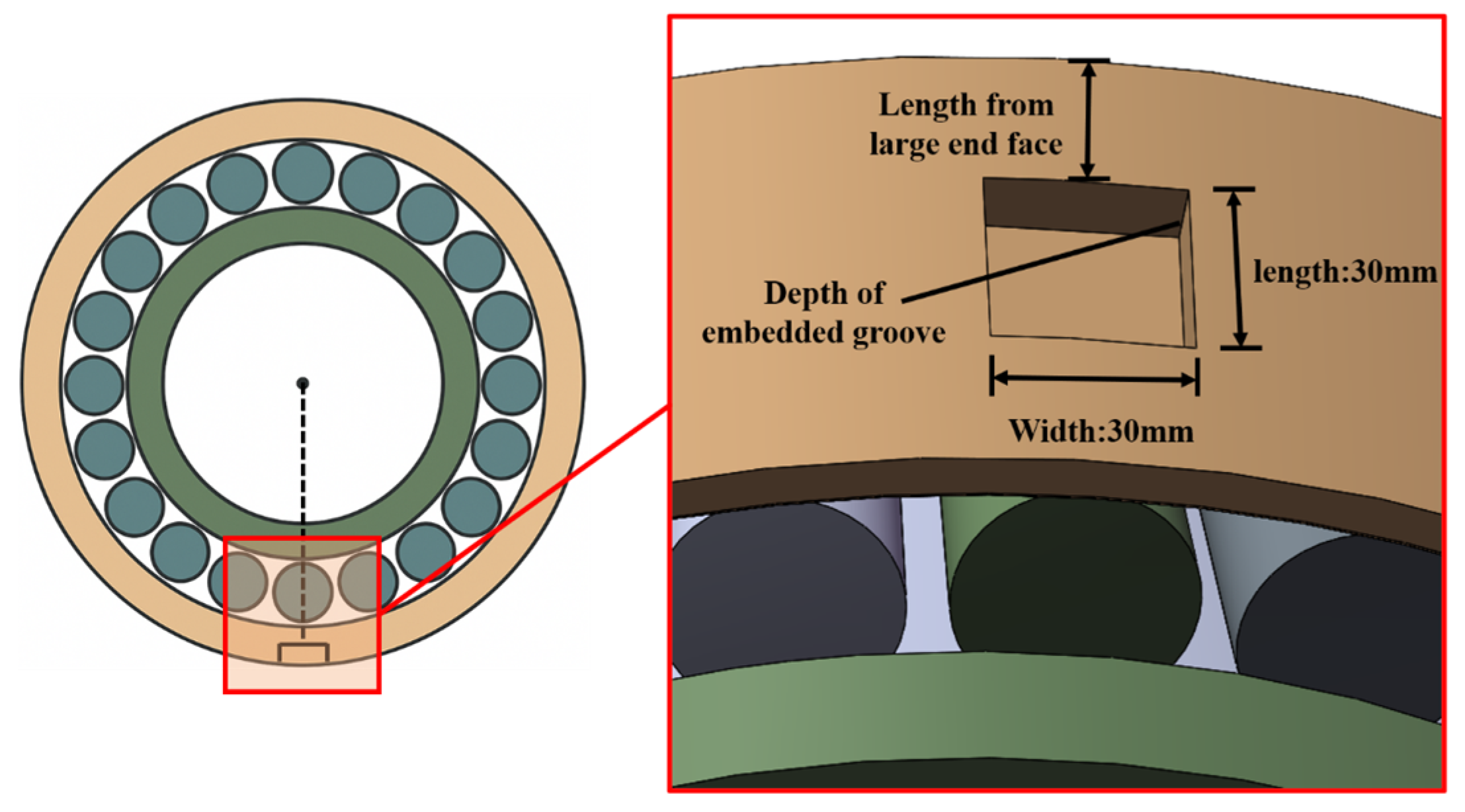
A rectangular groove is machined into the outer ring of the bearing, with a fixed groove length of 35 mm and width of 35 mm. The groove depth and the distance from the large end face are defined as parametric variables for structural evaluation.
The finite element model of the electric shovel bearing with embedded grooves, along with the dimensional schematic of the groove, is shown in Figure 2.
The bearing components were made of GCr15 high-carbon chromium bearing steel. This steel mainly contains 1.05% carbon (C), 1.55 chromium (Cr), 0.235% manganese (Mn), and 0.25% silicon (Si), with small amounts of nickel, copper, phosphorus, and sulfur as residual elements, and iron as the balance. The combination of high carbon and chromium contents provides superior hardness, wear resistance, and dimensional stability after heat treatment, making this material well-suited for heavy-duty bearing applications. The surface roughness of the raceways and grooves corresponds to grade II precision, with R a = 0.16   μ m for the raceway, and R a = 2.5   μ m for the non-functional surfaces. The machined slot surface exhibits a slightly higher roughness of approximately R a = 3.2   μ m .

3. Finite Element Simulation

To thoroughly evaluate the influence of the embedded groove structure on the thermo-mechanical response of heavy-duty shovel bearings, a multi-physics-based finite element simulation model was developed. The simulation workflow includes geometry construction, contact definition, meshing strategy, loading and boundary condition setup, coupled solution procedure, and validation of results. The simulation outputs not only support the subsequent structural optimization but also provide a theoretical basis for performance prediction of embedded structures under thermo-mechanical coupling.
Finite element simulations, including thermal–mechanical coupling analyses and post-processing of temperature and stress fields, were performed based on finite element model. The polar and three-dimensional contour plots presented in this study were generated directly within the visualization environment.

3.1. Model Setup

1.
Contact Definition
To accurately capture the contact interactions between rolling elements and raceways, localised sectional modeling was performed for the 24 rollers. Specifically, a 1 mm-thick contact slice was extracted from each roller, and 24 corresponding contact surface slices were defined on both the inner and outer rings. This configuration establishes 72 contact pairs among the rollers, inner ring, and outer ring.
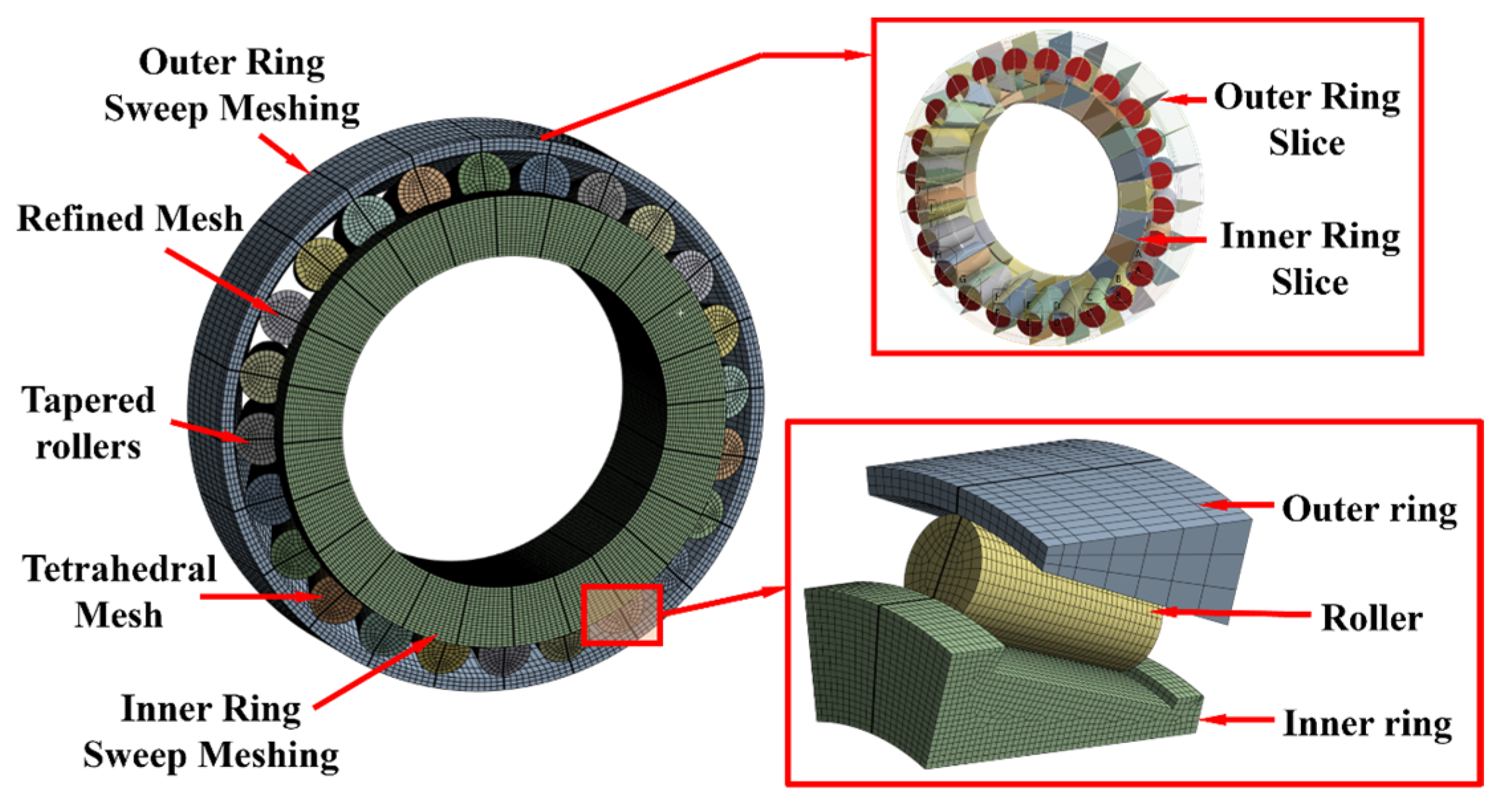
Such modeling ensures high-resolution identification of axial and radial contact stresses and load transmission paths, particularly in the vicinity of the embedded groove, thereby enhancing local simulation accuracy (see Figure 3).
2.
Finite Element Meshing Strategy
A partitioned meshing strategy combining local refinement with global coarseness was adopted to balance computational efficiency and simulation accuracy. The roller slices were meshed using swept elements with 7 divisions and a bias ratio of 8, resulting in an element size of 2.5 mm. The remaining parts of the rollers were meshed with tetrahedral elements of 4 mm size.
Similarly, swept meshing was applied to the 24 contact slices on the inner and outer rings, using 5 divisions per slice. For non-critical regions, the mesh sizes were set to 5 mm for the outer ring and 4 mm for the inner ring. The embedded groove region, being the core response zone, was locally refined to an element size of 2.5 mm to ensure accurate capture of stress concentrations and principal strains (see Figure 4).
3.
Load and Boundary Condition Setting
Regarding thermal boundary conditions, the heat transfer coefficients were determined based on the contact characteristics and environmental exposure of each surface, with distinctions made between natural and forced convection. To simplify the thermal loading strategy, the total frictional heat generation under rated service conditions was distributed proportionally across components using a ratio of inner ring: outer ring: rollers = 1:1:2. This approximates the actual heat source distribution. The initial structure temperature was set at 22 °C, and the ambient convection temperature was set at 25 °C.

3.2. Validation of Simulation Model

To assess the physical correctness and numerical accuracy of the finite element model, validation was conducted from two perspectives: contact load and contact stress. The simulation results were compared with theoretical calculations to evaluate the model’s reliability.
1.
Contact Load Distribution Verification
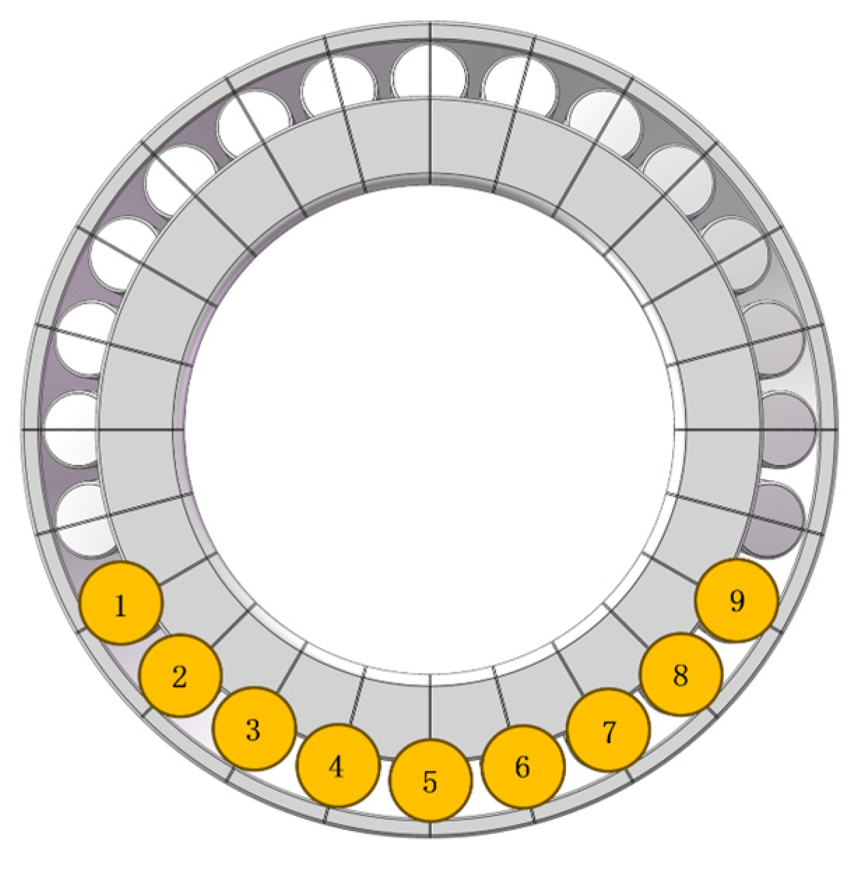
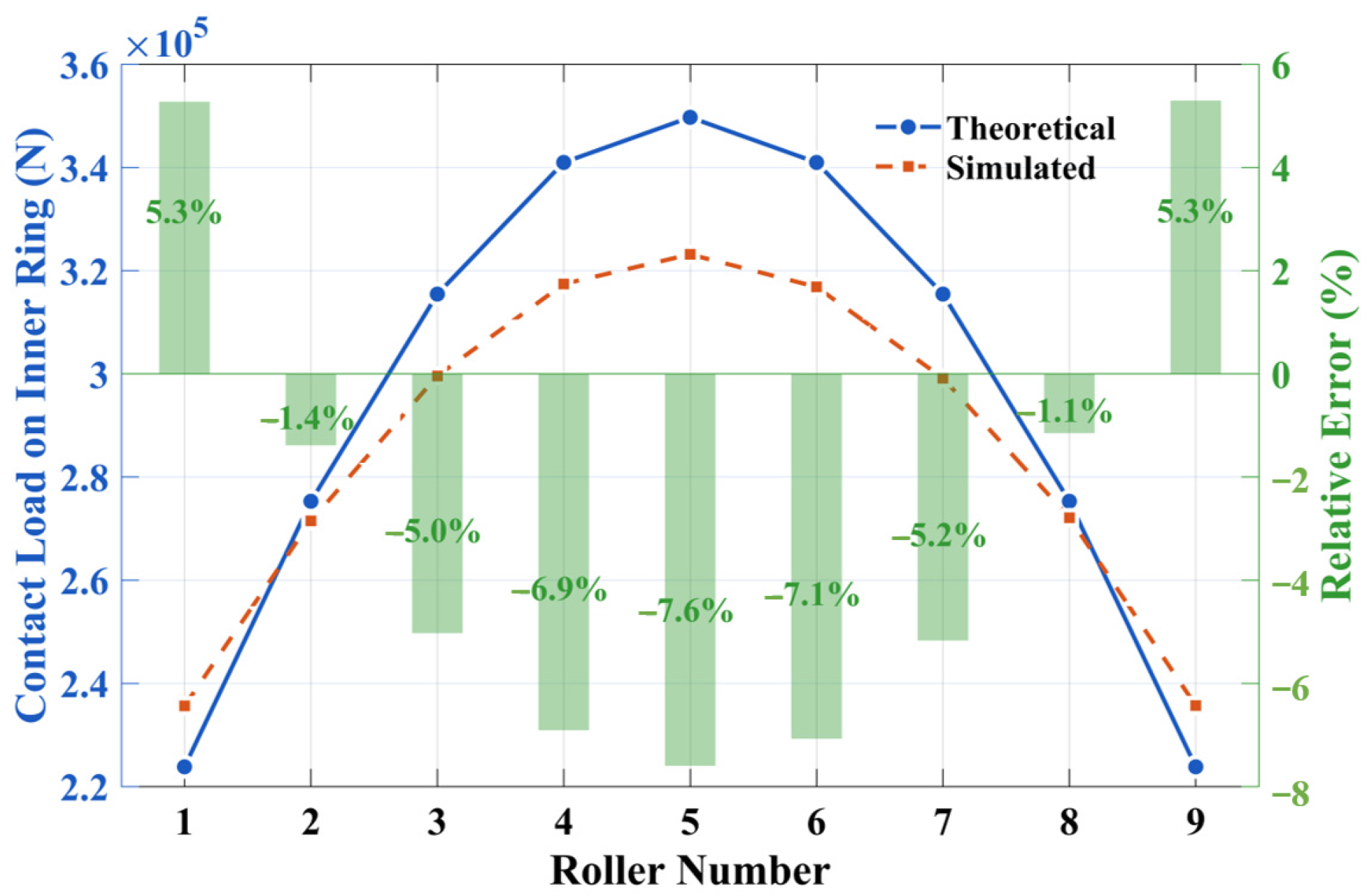
Nine rollers that bear the primary loads within the electric shovel bearing were selected as analysis objects and sequentially numbered, as shown in Figure 3. The contact load response of each roller was extracted and compared with the corresponding theoretical values calculated by the contact load model. The relative errors between the two sets of results were plotted in Figure 5.
The results show that under rated load conditions−axial load of 1333.7 kN, radial load of 1820 kN, and moment of 93,577 N·m−the maximum relative error between simulated and theoretical contact loads for rollers 1 through 9 does not exceed 7.6%. This demonstrates that the proposed model exhibits high accuracy in predicting contact load distributions.
2.
Contact Stress Verification
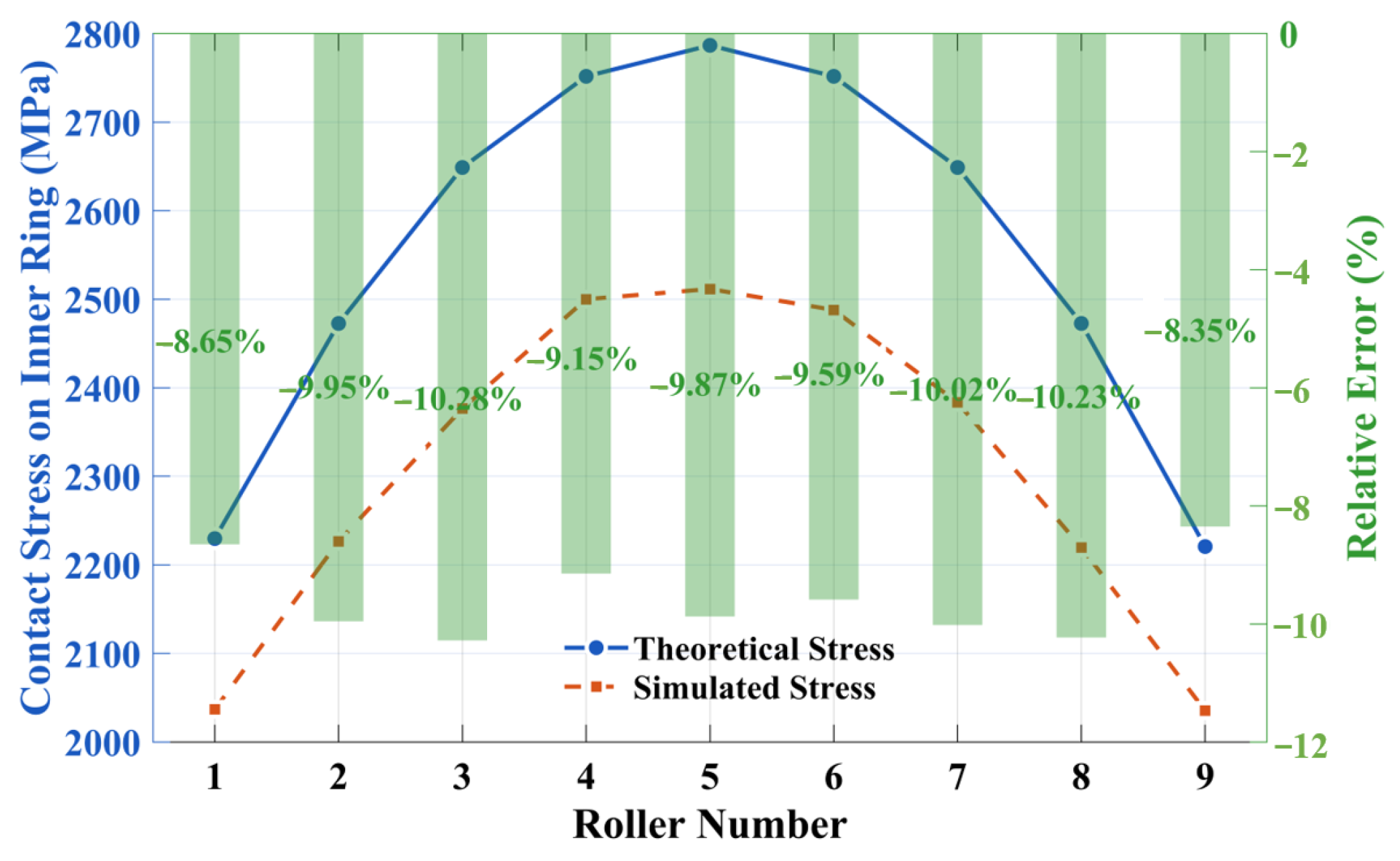
Based on Hertzian contact theory, the contact stress between rollers and the inner ring was calculated and compared with the average contact stress extracted from the simulation platform, as shown in Figure 6. The relative error between the simulation and theoretical values remains within approximately 10%, confirming that the model retains strong predictive capability for mechanical responses even under extreme contact conditions. The model is therefore suitable for subsequent quantitative analysis of stress concentration effects in embedded structures.
The above validation results indicate that the proposed finite element model demonstrates satisfactory predictive accuracy for two key response parameters: contact load and contact stress. Moreover, the model maintains numerical stability under realistic service conditions, making it a reliable computational platform for future multi-objective performance evaluation and structural optimization involving thermo-mechanical–sensing interactions.

4. Experimental Verification

To validate the accuracy of the proposed multi-physics coupling model, an experimental test platform was designed and constructed specifically for the bearing used in electric shovels. Thermal response and strain response experiments were conducted separately. By comparing the measured temperature and strain distributions in key bearing regions with simulation results, the predictive capability of the finite element model under real operating conditions is assessed. This also provides experimental support for subsequent structural optimization and sensor deployment.

4.1. Experimental Platform and Sensor Layout

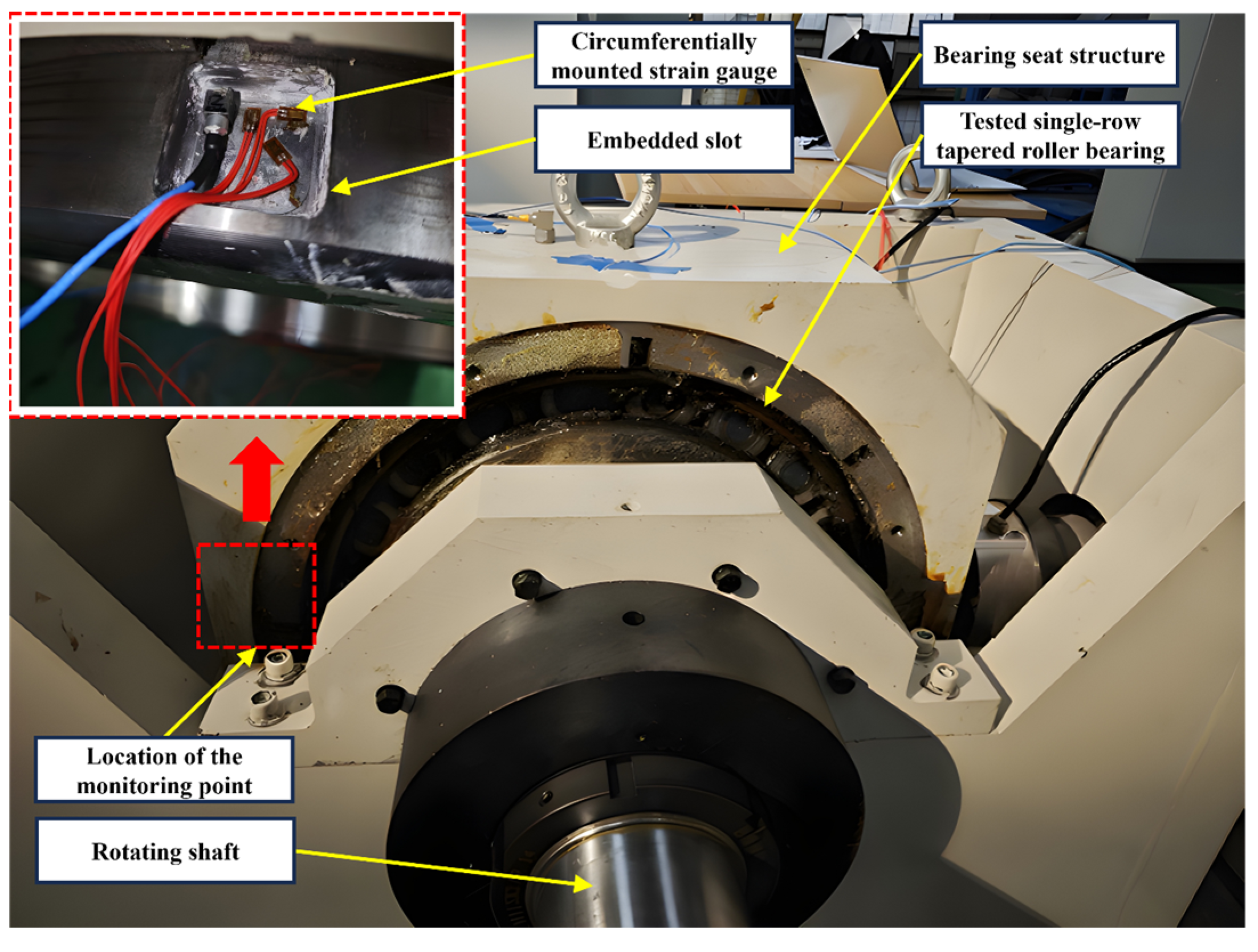
The experimental system consists of a motor drive unit, a hydraulic loading system, a bearing seat assembly, embedded groove sensor components, and a data acquisition system, as shown in Figure 7. The motor supplies a constant rotational speed input, while the hydraulic system applies combined axial and radial loads to replicate typical operational load conditions of bearings.
A rectangular embedded groove was machined on the outer ring of the bearing, and strain gauges were affixed at the bottom of the groove as sensing elements. These gauges were directionally aligned with the radial load and placed in the main load-bearing region to ensure the acquisition of representative and sensitive signals. A high-sensitivity signal amplifier and a multi-channel data acquisition card were employed to guarantee clarity and real-time response during testing.

4.2. Thermal Response Experiment

The thermal response experiment was conducted under the following operating conditions (see Table 2):
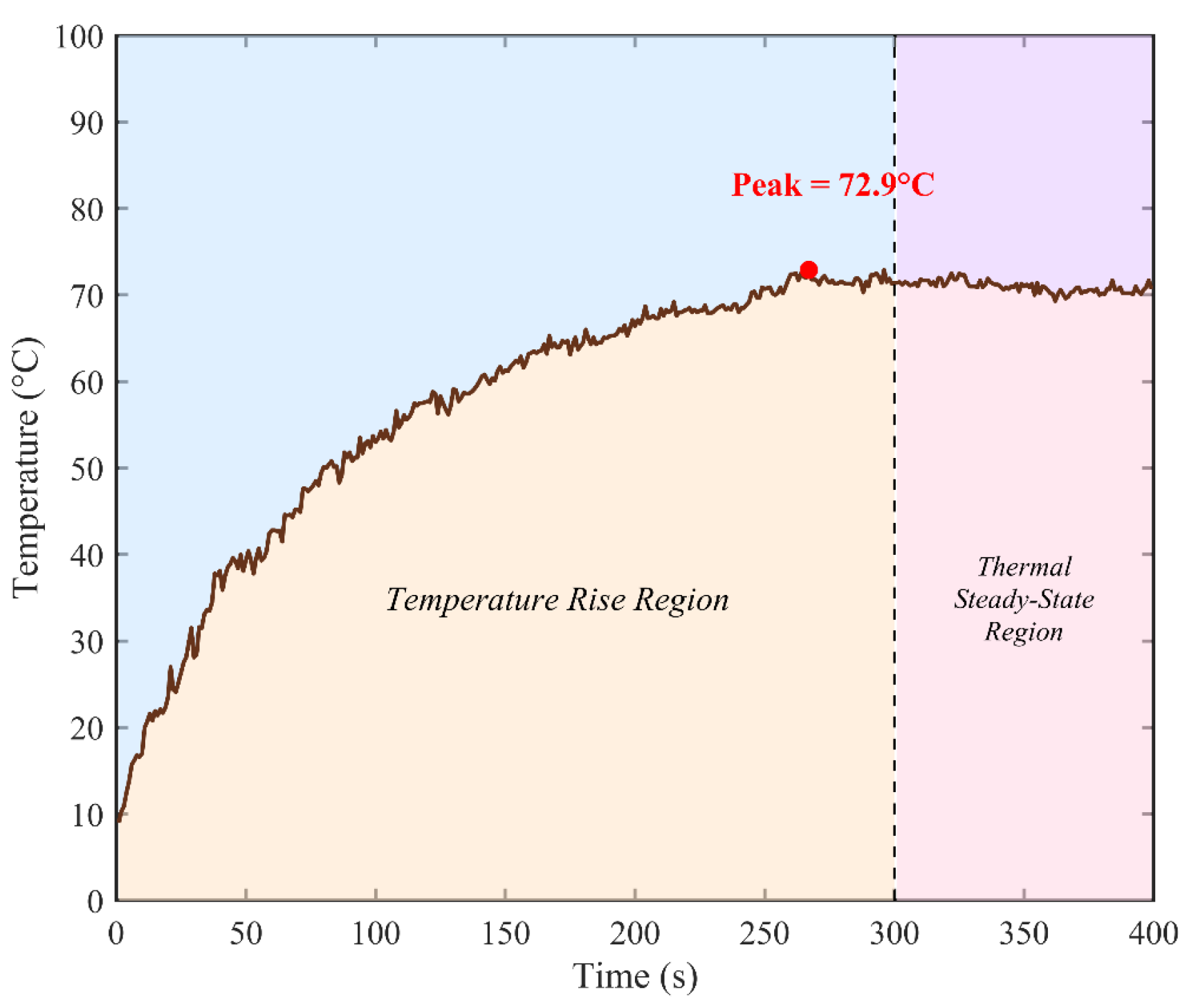
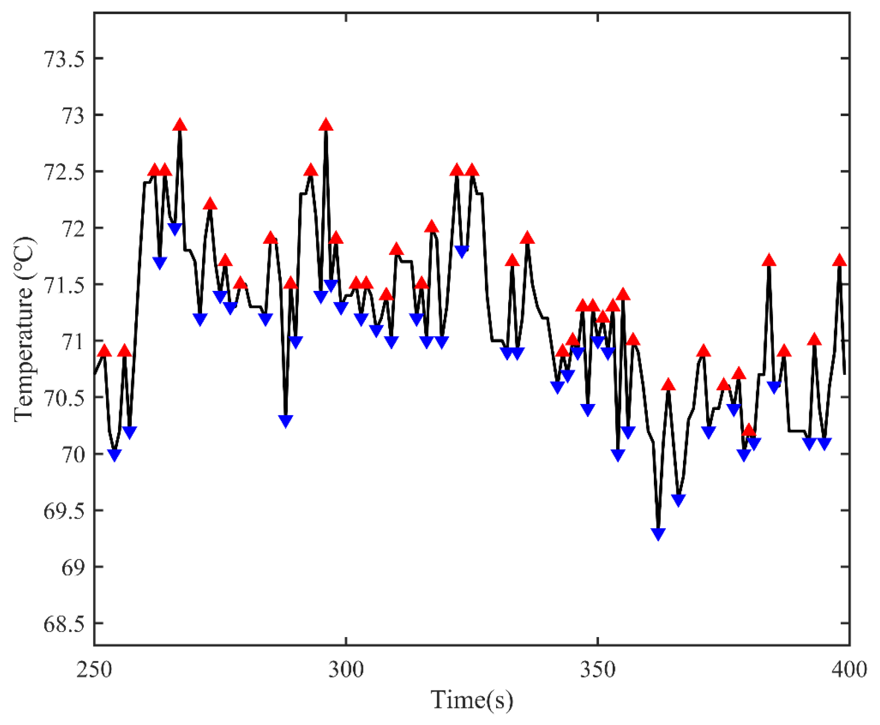
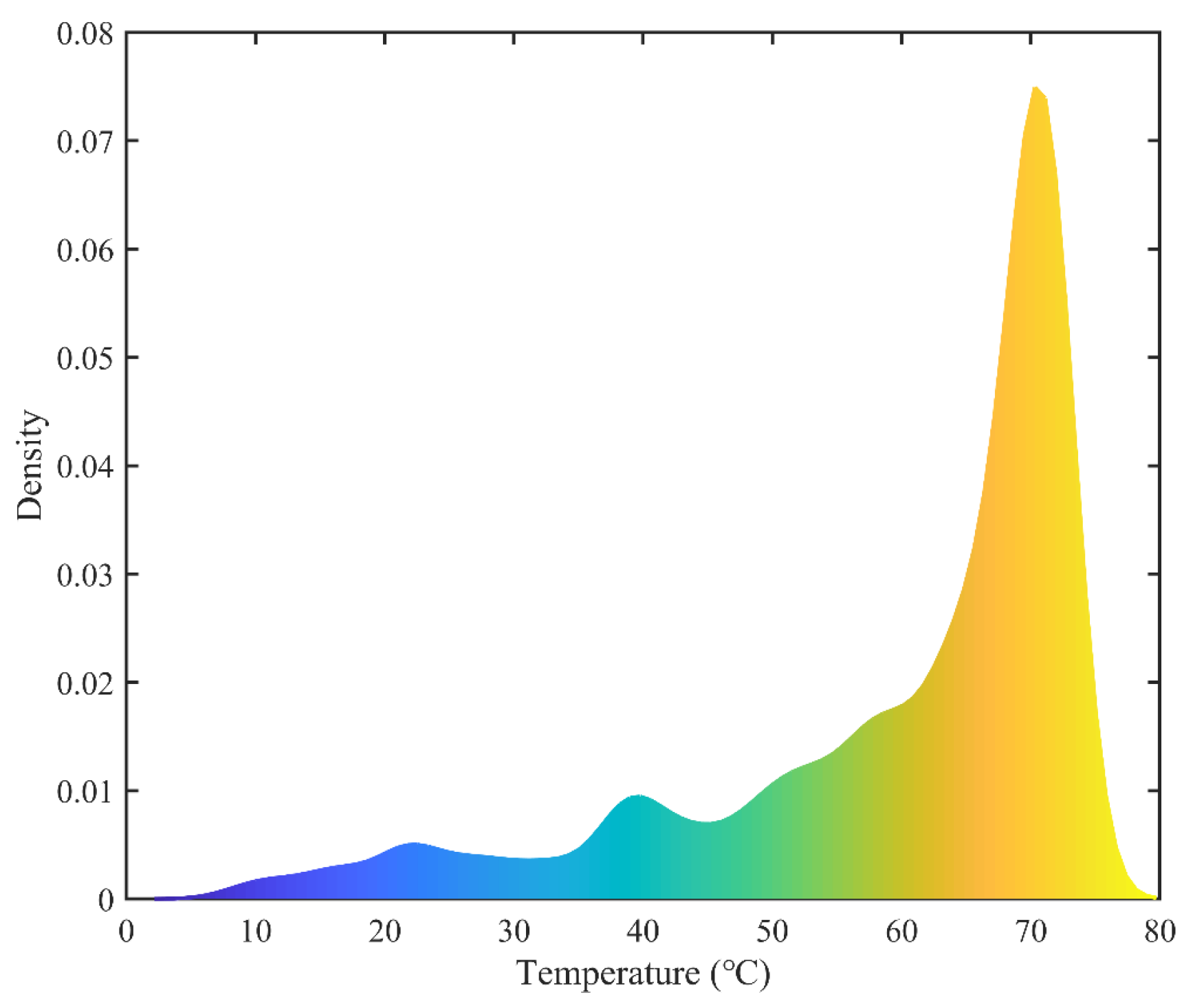
After the bearing reached thermal stability, the temperature of its components was continuously monitored using a combination of type-K thermocouples and an infrared thermometer. The thermocouples were attached to the outer ring surface to record the local temperature variation, while the infrared thermometer was used to measure the temperatures of the inner ring, rollers, and cage without contact interference. Measurements were taken at 60-s intervals over a total duration of 6 h until steady-state conditions were achieved. During the tests, the ambient temperature was maintained at approximately 25 °C, and No. 0 lithium-based grease was used as the lubricant. Figure 8, Figure 9 and Figure 10 illustrate the temperature evolution of the inner ring, where the temperature gradually increases and stabilizes after approximately 300 s, indicating that thermal equilibrium has been reached.
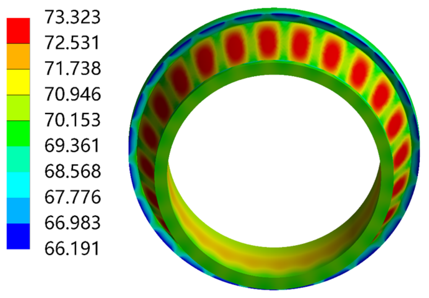
The simulation analysis identifies the inner ring as the region with the most significant temperature rise. The maximum steady-state temperature predicted by the model is 73.323 °C, while the experimentally measured peak temperature is 72.9 °C. This result confirms that the developed thermo-mechanical coupling model effectively predicts the temperature and reflects the influence of the embedded groove structure on thermal field distribution (see Figure 8 and Figure 11).

4.3. Strain Response Experiment

The strain response experiment was conducted under the following conditions (see Table 3):
Strain gauges were installed axially at the bottom of the embedded groove and oriented in the direction of the radial load to ensure that the captured signals were both representative and sensitive.
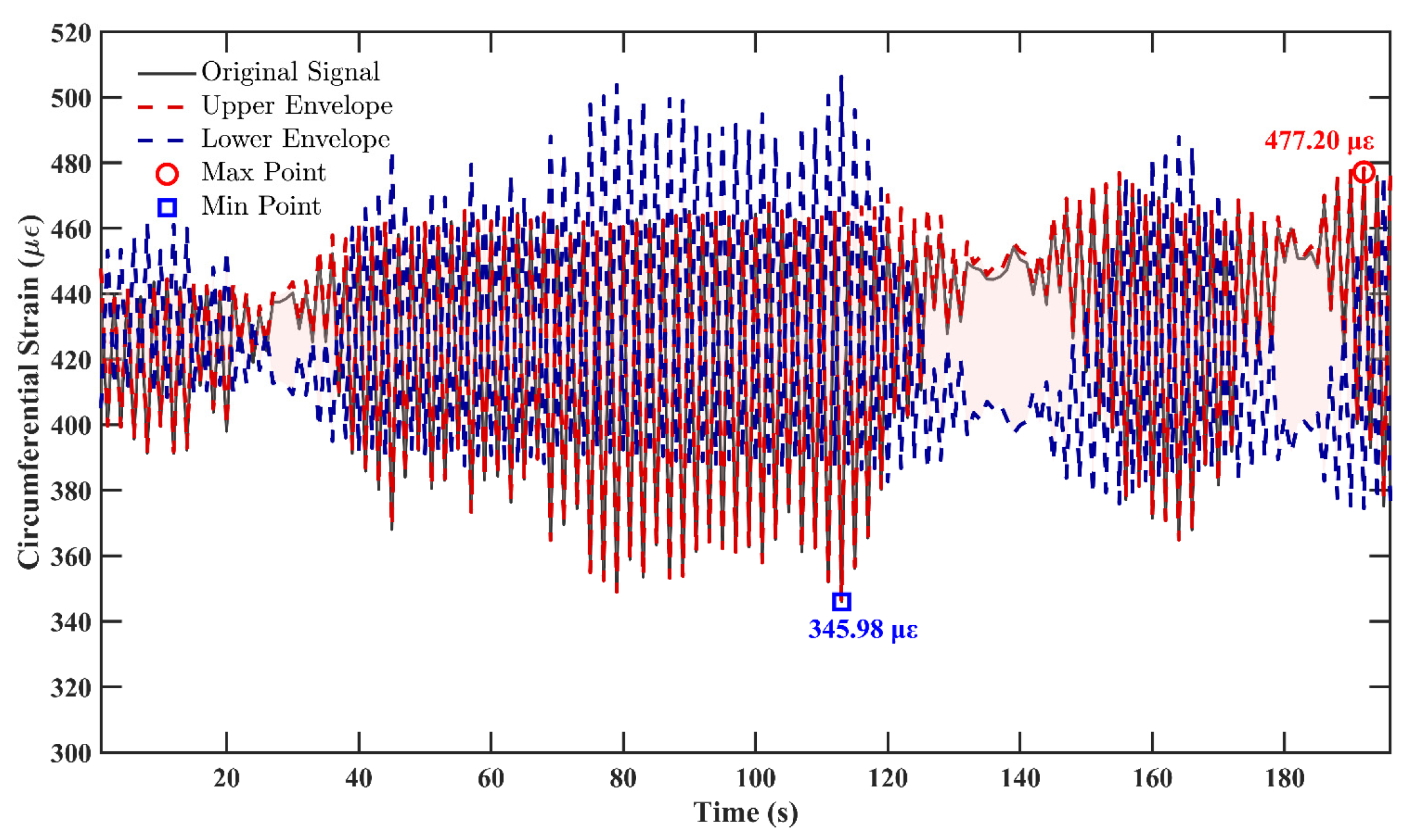
A multi-channel strain acquisition system was used to synchronously record the strain variation under the thermo-mechanical coupling condition, as illustrated in Figure 12. The experimental results show that the principal strain in the embedded groove region ranges from 345.98 to 477.20 µε, with a stable response and no significant fluctuations. The corresponding simulation predictions yield values between 320.71 and 484.86 µε, and the maximum relative error is 7.3%. The consistency in magnitude between experimental and simulation data verifies the accuracy of the finite element model in simulating strain response.

4.4. Comprehensive Analysis

From both thermal and strain response perspectives, the simulation predictions exhibit good consistency with experimental measurements, confirming that the developed thermo-mechanical coupling model has a high predictive capability.
The experimental results also demonstrate that the embedded groove region is highly sensitive to thermo-mechanical variations. This makes it an ideal location for sensor deployment, suitable for implementing intelligent sensing functions such as fault identification and load monitoring.

5. Structural Optimization and Design Recommendations

To systematically assess the influence of groove geometry on the thermo-mechanical–sensing performance of the bearing, a multi-objective performance evaluation framework was constructed based on the previously established finite element platform. A parametric analysis method was employed to extract key response indicators, enabling structural optimization aimed at improving heat dissipation efficiency, mechanical strength, and signal sensitivity in a coordinated manner.

5.1. Performance Metrics and Composite Evaluation Function

Considering the three performance aspects—thermal response, structural response, and sensing response—a multidimensional performance evaluation index system was established as follows:
1.
Thermal response indicator: Maximum steady-state temperature, which reflects internal heat accumulation. Higher temperatures indicate poorer heat dissipation. All configurations are normalised against the reference case without a groove.
2.
Structural response indicator: The ratio of maximum equivalent stress to material yield strength, which reflects the safety margin. A smaller ratio indicates higher structural integrity.
3.
Sensing response indicator: Maximum principal strain in the embedded groove region, representing strain sensitivity. Within acceptable strain limits, higher strain values are favourable for signal acquisition.
Based on the above, a composite performance evaluation function is proposed:
f = α T    max T 0 + β σ e q σ y γ ε    max ε 0
where
T m a x : maximum steady-state temperature of the current configuration;
T 0 : reference structure (33.989 °C, groove-free case);
σ m a x : maximum equivalent stress;
σ y : material yield strength (GCr15, taken as 550 MPa);
ε m a x : maximum principal strain in groove region;
ε 0 : target strain for sensing (taken as 1200 µε);
α , β , γ : weighting coefficients, with α + β + γ = 1 .
To balance the three performance aspects, the weights are set as α = 0.5 , β = 0.25 , γ = 0.25 .
A lower value of f indicates better overall performance.

5.2. Actual Operating Condition Settings

To ensure that the optimization results are practically applicable in engineering scenarios, the applied loads in the simulation are set based on the typical operating conditions of the electric shovel during open-pit mining tasks as shown in Figure 13. The load conditions used in the simulation are summarized in Table 4.
The total generated heat is distributed to the bearing components in a ratio of inner ring: outer ring: rollers = 1:1:2, consistent with earlier thermal modeling assumptions. The ambient convection temperature is set at 25 °C, and the initial structural temperature is set at 22 °C to simulate the early start-up phase of the equipment.

5.3. Parametric Analysis Methodology

In this study, the geometric parameters of the embedded groove—namely groove depth and the axial distance from the large end face—are defined as variables in a parametric model. The combinations of groove geometry parameters are shown in Table 5.
A total of 21 parameter combinations were generated. For each configuration, steady-state thermo-mechanical coupled simulations were conducted. Key response values—including maximum temperature, maximum equivalent stress, and maximum principal strain—were extracted and substituted into the composite performance function for scoring and ranking.

5.4. Influence of Groove Structure on Thermo-Mechanical Responses

Based on the results of 21 parametric simulations, the effects of different combinations of groove depth and groove position were evaluated in terms of three performance dimensions: temperature, stress, and strain. Each response characteristic was analyzed individually, followed by a composite performance evaluation based on the previously defined function.
(1)
Thermal Response Analysis:
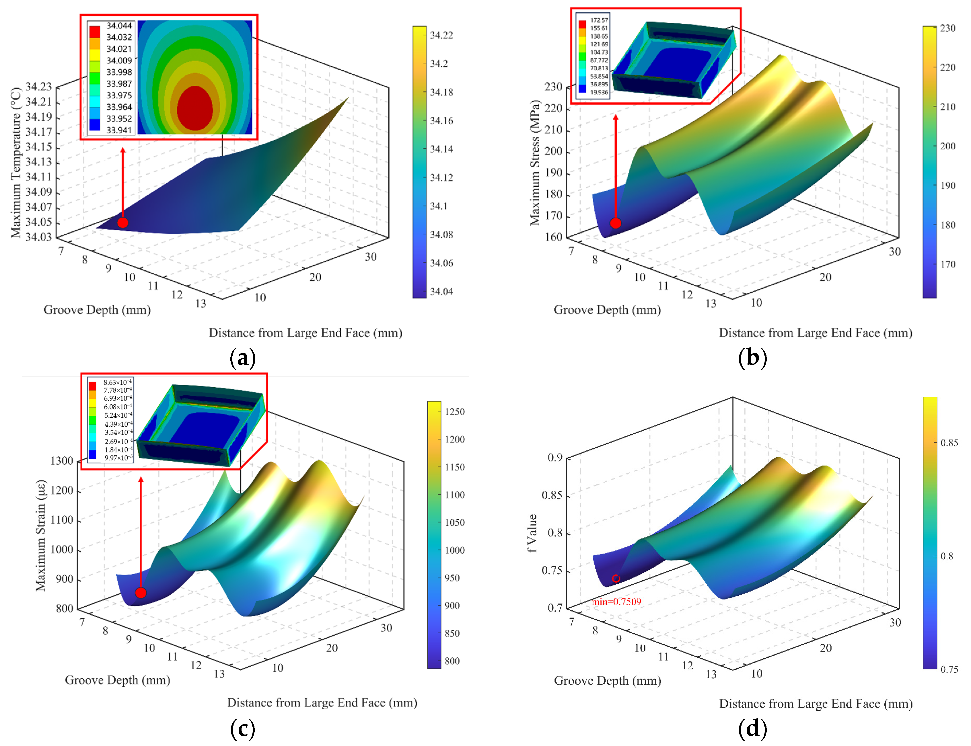
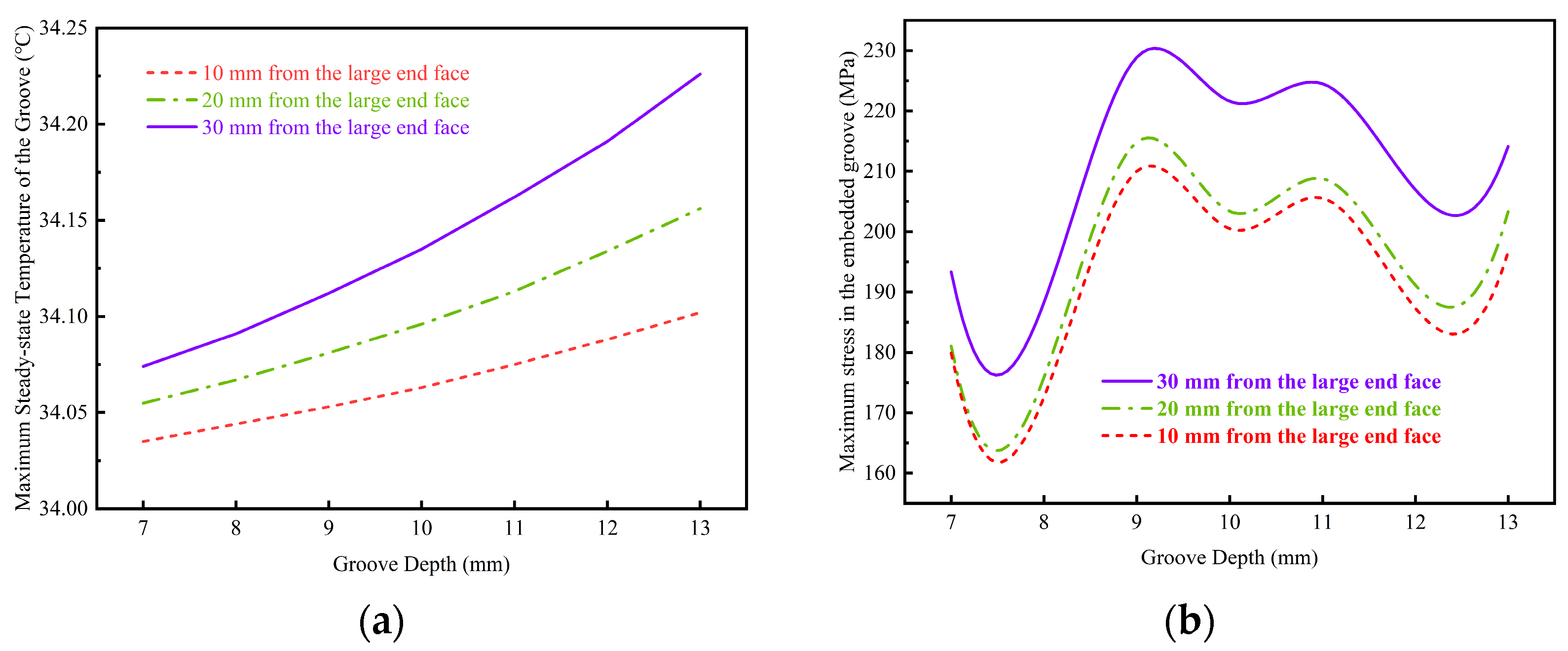
As shown in Figure 14a and Figure 15a, the thermal response of the bearing structure with embedded grooves exhibits significant dependence on groove depth and axial position. When the groove depth is between 7–9 mm and the distance from large end face is 10–20 mm, the heat transfer path from the frictional heat source to the external environment is relatively short, leading to lower thermal resistance and facilitating efficient heat dissipation. In contrast, increasing groove depth or shifting the position farther from the end face increases the thermal diffusion path and resistance, resulting in a more pronounced temperature rise. The optimal thermal range is therefore 7–9 mm in depth and 10–20 mm in position.
(2)
Structural Stress Analysis:
As illustrated in Figure 14b and Figure 15b, the maximum equivalent stress in the embedded groove region rises with increasing groove depth, and this effect becomes more pronounced at greater axial distances. When the groove depth is 8–9 mm and located 20 mm from the large end face, the minimum stress response is observed. This suggests that moderate groove depth and central positioning contribute to structural reliability.
(3)
Strain Sensing Analysis:
As shown in Figure 14c and Figure 15c, the maximum principal strain increases with groove depth, enhancing strain sensitivity. Greater axial distances also lead to higher strains. Although a larger strain is favourable for signal acquisition, it must be balanced against stress limitations. The configuration of 8–9 mm depth at 20 mm position provides both high sensitivity and acceptable strength.
(4)
Comprehensive Performance Evaluation:
Figure 14d presents the composite performance function f for all 21 parameter combinations. The configuration with an 8 mm groove depth and a 20 mm position achieves the lowest function value, indicating optimal trade-offs across thermal, mechanical, and sensing dimensions. Configurations such as 7 mm–20 mm and 9 mm–20 mm also show good performance. In contrast, groove depths above 10 mm or axial positions at 30 mm result in significantly increased f values and degraded overall performance.

6. Conclusions

This study presents an integrated research framework encompassing multi-physics modeling, finite element simulation, experimental validation, and structural optimization to investigate the thermo-mechanical behavior and multi-objective performance of embedded-groove sensor-embedded rings in heavy-duty electric shovel bearings. The key conclusions are summarized as follows:
(1)
A multi-physics coupling model tailored to sensor-embedded bearing rings with embedded grooves was developed and verified by experiments. The model incorporates frictional heat generation, complex heat transfer boundaries, and contact stress distribution. A sequentially coupled thermo-mechanical simulation strategy, along with local slicing and mesh refinement, enables detailed analysis of interactions among rollers, raceways, and grooves, providing a foundation for performance evaluation.
(2)
The proposed model was validated through thermal and strain response experiments. The results show high consistency between simulation and experimental measurements, confirming the model’s accuracy.
(3)
A multi-objective performance function was proposed to evaluate the synergy of thermal–mechanical responses. The function integrates maximum steady-state temperature, equivalent stress, and principal strain with weighting coefficients, allowing for quantitative ranking of design configurations.
(4)
A relatively optimal groove configuration was identified. Among 21 tested parameter combinations, the configuration with an 8 mm groove depth and a 20 mm axial position achieved the best overall performance in thermal dissipation, structural safety, and strain sensitivity. This confirms the feasibility of the integrated structure–sensing design strategy in intelligent bearing applications.
The proposed modeling and validation approach provides theoretical guidance for the embedded design and performance assessment of intelligent heavy-duty bearings. The findings offer practical insights into improving the safety of key components in large-scale mining equipment.
Although the proposed method shows good ability in predicting the thermo-mechanical behavior of the sensor-embedded bearing rings, some limitations remain. The current analysis assumes steady operating conditions and does not fully capture the influence of dynamic load fluctuations, which may affect the temperature and stress distributions in practical applications. Future research will focus on integrating real-time temperature and stress monitoring as well as advanced multi-physics coupling techniques to further enhance the predictive capability of the model. In addition, experimental investigations under variable speed and load conditions will be conducted to validate and generalize the proposed approach.

Author Contributions

Conceptualization, L.W., C.H. and H.T.; Methodology, L.W., C.H. and H.T.; Validation, C.H.; Formal analysis, F.L. and C.H.; Investigation, L.W., F.L., C.H. and H.T.; Resources, F.L. and H.T.; Data curation, F.L. and C.H.; Writing—Original draft, C.H., F.L., and L.W.; Writing—Review & editing, L.W., F.L., C.H. and H.T.; Visualization, F.L. and C.H.; Supervision, H.T.; Project administration, F.L.; Funding acquisition, L.W. All authors have read and agreed to the published version of the manuscript.

Funding

This work was supported by the National Key R&D Program of China under Grant 2023YFB3406102, and by the Hunan Natural Science Foundation Project under Grant 2025JJ60317 and 2025JJ80228.

Data Availability Statement

The original contributions presented in this study are included in the article.

Conflicts of Interest

The authors declare that they have no known competing financial interests or personal relationships that could have appeared to influence the work reported in this paper.

Abbreviations

FaAxial load (N)
FrRadial load (N)
NuNusselt number
GrGrashof number
PrPrandtl number

References

  1. Jirigala; Sun, J.L. Comparative study on critical mineral resources policies of China and foreign countries. World Scitech RD 2025, 47, 94–106. [Google Scholar] [CrossRef]
  2. Wang, H.N. Intelligent Structural Design and Research of Rolling Bearings. Master’s Thesis, North University of China, Taiyuan, China, 2023. [Google Scholar]
  3. Wang, Y.P. Development status and trends of informationization and intelligence of large electric shovel at home and abroad. Mech. Manag. Dev. 2021, 36, 283–285. [Google Scholar] [CrossRef]
  4. Li, X.D.; Liu, C.; Li, J.M.; Baghdadi, M.; Liu, Y.C. A multi-sensor environmental perception system for an automatic electric shovel platform. Sensors 2021, 21, 4355. [Google Scholar] [CrossRef] [PubMed]
  5. Wang, L.C.; Shao, A.L.; Qu, F.M.; Yue, X.T.; Wang, H.Y.; Zhang, X.F.; Liu, X.B. Current status and prospects of mining technology in metal mines. Chin. J. Eng. 2025, 47, 971–983. [Google Scholar] [CrossRef]
  6. Chang, H. Research on Multiple Mechanism Cooperative Control System of Intelligent Large Mining Electric Shovel. Master’s Thesis, Harbin Institute of Technology, Harbin, China, 2021. [Google Scholar] [CrossRef]
  7. Qian, L.; Xu, Q.F.; Wang, J.X.; Zhang, S. Design of fault diagnosis and maintenance system of mechanical and electrical equipment in open-pit coal mines. Mod. Manuf. Technol. Equip. 2024, 60, 52–54. [Google Scholar] [CrossRef]
  8. El-Thalji, I.; Jantunen, E. A summary of fault modeling and predictive health monitoring of rolling element bearings. Mech. Syst. Signal Process. 2015, 60, 252–272. [Google Scholar] [CrossRef]
  9. Jin, X.; Chen, Y.M.; Wang, L.; Han, H.L.; Chen, P. Failure prediction, monitoring and diagnosis methods for slewing bearings of large-scale wind turbine: A review. Measurement 2021, 172, 108855. [Google Scholar] [CrossRef]
  10. Ma, J.P.; Zhuo, S.; Li, C.W.; Zhan, L.W.; Zhang, G.Z. Study on noncontact aviation bearing faults and speed monitoring. IEEE Trans. Instrum. Meas. 2021, 70, 1–21. [Google Scholar] [CrossRef]
  11. Cocconcelli, M.; Strozzi, M.; Molano, J.C.C.; Rubini, R. Detectivity: A combination of Hjorth’s parameters for condition monitoring of ball bearings. Mech. Syst. Signal Process. 2022, 164, 108247. [Google Scholar] [CrossRef]
  12. Zmarzly, P. Analysis of Technological Heredity in the Production of Rolling Bearing Rings Made of AISI 52100 Steel Based on Waviness Measurements. Materials 2022, 15, 3959. [Google Scholar] [CrossRef] [PubMed]
  13. Wang, M.; Yang, S.P.; Liu, Y.Q.; Chen, Y.H.; Zhang, K. Establishment of the thermo-mechanical coupling model of axle box bearings with track irregularity excitation and analysis of its temperature characteristics. Appl. Math. Mech. 2024, 45, 1965–1986. [Google Scholar] [CrossRef]
  14. Jing, H.B.; Wang, N.; Li, D.H.; Zhao, D.Y.; Wang, P.; Zhang, C.M. Analysis on lubrication characteristics of a novel strain sensor-embedded water-lubricated bearing. Lubr. Eng. 2025, 1–10. Available online: https://link.cnki.net/urlid/44.1260.th.20250317.1100.028 (accessed on 18 March 2025).
  15. Yuan, Z.K. Development of a Self-Powered Sensing System for Intelligent Bearing. Master’s Thesis, Harbin Institute of Technology, Harbin, China, 2023. [Google Scholar] [CrossRef]
  16. Russell, T.; Shafiee, A.; Conley, B.; Sadeghi, F. Evaluating load distribution at the bearing-housing interface using thin film pressure sensors. Tribol. Int. 2022, 165, 107293. [Google Scholar] [CrossRef]
  17. Alian, H.; Konforty, S.; Ben-Simon, U.; Klein, R.; Tur, M.; Bortman, J. Bearing fault detection and fault size estimation using fiber-optic sensors. Mech. Syst. Signal Process. 2019, 120, 392–407. [Google Scholar] [CrossRef]
  18. Wang, N.; Wei, Y.J.; Zhang, N.; Wang, D.D.; Wang, M.W.; Zhang, C.M. Wireless sensor monitoring method for film pressure of embedded water-lubricated bearings. J. Electron. Meas. Instrum. 2024, 38, 38–46. [Google Scholar]
  19. Shao, Y.M.; Tu, W.B.; Zhou, X.J.; Ge, L. Smart bearing based on embedded multi-parameter sensors. Chin. J. Mech. Eng. 2010, 21, 2527–2531. [Google Scholar]
  20. Zhang, W.Y.; Chen, J.H.; Hua, G.R.; Wang, H. Research on embedded smart bearing structure analysis and vibration monitoring system design. J. Mech. Strength 2022, 44, 1293–1299. [Google Scholar] [CrossRef]
  21. Kang, K.; Kim, S.-W.; Yoon, K.; Choi, D.-H. Robust design optimization of an angular contact ball bearing under manufacturing tolerance. Struct. Multidiscip. Optim. 2019, 60, 1645–1665. [Google Scholar] [CrossRef]
  22. Zhao, H.; Fu, C.; Zhang, Y.C.; Wan, Z.Q.; Lu, K. A non-probabilistic reliability-based design optimization method via dimensional decomposition-aided Chebyshev metamodel. Reliab. Eng. Syst. Saf. 2025, 262, 111208. [Google Scholar] [CrossRef]
  23. Xiao, J.W.; Zhang, Y.C.; Chen, S.; Ding, X.X.; Shao, Y.M. Optimization method for information sensing measuring points of embedded smart bearing. Bearing 2023, 2, 12–18. [Google Scholar] [CrossRef]
  24. Bhat, J.A.; Harmain, G.A.; Najar, F.A. Alleviating thermal challenges in hydrodynamic bearings: A novel approach through thrust bearing pads with embedded cooling circuitry and deep recess. Tribol. Int. 2024, 194, 109438. [Google Scholar] [CrossRef]
  25. Luan, W.L.; Liu, Y.; Wang, Y.L.; Xu, F.C. Effect of herringbone groove structure parameters on the static performance of gas foil herringbone groove thrust bearings. Tribol. Int. 2023, 177, 107979. [Google Scholar] [CrossRef]
  26. Brito, F.P.; Miranda, A.S.; Claro, J.C.P.; Fillon, M. Experimental comparison of the performance of a journal bearing with a single and a twin axial groove configuration. Tribol. Int. 2012, 54, 1–8. [Google Scholar] [CrossRef]
  27. Brito, F.P.; Miranda, A.S.; Fillon, M. Analysis of the effect of grooves in single and twin axial groove journal bearings under varying load direction. Tribol. Int. 2016, 103, 609–619. [Google Scholar] [CrossRef]
  28. Ren, L.J.; Yan, W.J.; Chen, K.; Li, K.; Wang, Q.; Zhang, G.P. Modeling method and experimental study on thermal force coupling characteristics of grinding machine. Mach. Tool Hydraul. 2024, 52, 62–67. [Google Scholar] [CrossRef]
  29. Chang, Z.Y.; Hou, L.; Masarati, P.; Linn, R.Z.; Li, Z.G.; Chen, Y.S. Modeling and nonlinear analysis of a coupled thermo-mechanical dual-rotor system. Nonlinear Dyn. 2024, 112, 17811–17842. [Google Scholar] [CrossRef]
  30. Tan, Y.Q.; Dang, J.; Igarashi, A.; Himeno, T.; Hamada, Y. Hysteretic restoring force model of high damping rubber bearings including thermo-mechanical coupled effect. Eng. Struct. 2023, 277, 115449. [Google Scholar] [CrossRef]
  31. Yang, R.Z. Analysis on Slip Characteristics of Double-Row Angle Contact Ball Bearings Based on Heat-Mechanical Coupling. Master’s Thesis, Anhui Polytechnic University, Wuhu, China, 2024. [Google Scholar] [CrossRef]
  32. Su, C.; Chen, W.F. An improved model of motorized spindle for forecasting temperature rise based on thermal network method. Int. J. Adv. Manuf. Technol. 2022, 119, 5969–5991. [Google Scholar] [CrossRef]
  33. Zhan, Z.Q.; Wan, S.K.; Li, X.H.; Fang, B. Thermal behavior prediction of the spindle-bearing system based on the adaptive thermal network modeling method. Eng. Appl. Artif. Intell. 2025, 145, 110199. [Google Scholar] [CrossRef]
  34. Gao, Z.; Qi, X.Y.; Chang, L.; Ding, C. Thermal structure coupling calculation of motorized spindle based on thermal network method. Mod. Manuf. Eng. 2021, 6, 75–82. [Google Scholar] [CrossRef]
  35. Wang, L.K.; Hu, C.; Liu, F.Y.; Tang, H.B. Thermo-mechanical coupled characteristics for the non-axisymmetric outer ring of the high-speed rail axle box bearing with embedded intelligent sensor slots. Symmetry. 2025, 17, 1667. [Google Scholar] [CrossRef]
  36. Zhao, W.Y. Thermal Coupling Analysis of FAG Axle Box Bearing in High Speed EMU. Master’s Thesis, North China University of Technology, Beijing, China, 2024. [Google Scholar] [CrossRef]
  37. Zhang, J.H.; Yu, Y.J.; Xue, Y.J.; Li, J.S. Transient thermal-mechanical coupling analysis of high-speed cylindrical roller bearing. Manuf. Autom. 2024, 46, 161–165. [Google Scholar] [CrossRef]
  38. An, J.Q. Thermal Structure Coupling Analysis of Angular Contact Ball Bearings. Master’s Thesis, Shenyang University of Chemical Technology, Shenyang, China, 2020. [Google Scholar] [CrossRef]
  39. Song, D.L.; Li, X.Y.; Zheng, Z.J.; Dong, J.X.; He, P. Design of high speed train bogie bearing test-bed based on multi-physical field coupling monitoring. Exp. Technol. Manag. 2022, 39, 16–22. [Google Scholar] [CrossRef]
  40. Wang, L.K.; Hu, C.; Hu, L.; Liu, F.Y.; Tang, H.B. An investigation on the mechanical characteristics of railway locomotive axle box bearings with sensor-embedded slots. Machines 2025, 13, 358. [Google Scholar] [CrossRef]
  41. Deng, S.E.; Jia, Q.Y. Design Principles of Rolling Bearings; China Standards Press: Beijing, China, 2008. [Google Scholar]
  42. Tao, W.Q. Heat Transfer, 5th ed.; Higher Education Press: Beijing, China, 2019. [Google Scholar]
Figure 1. Flowchart of thermomechanical coupling modeling.
Machines 13 01008 g001
Figure 2. Bearing model with recessed groove and dimensional drawing of recessed groove.
Machines 13 01008 g002
Figure 3. Numbered sectional schematic of bearing rollers.
Machines 13 01008 g003
Figure 4. Meshing diagram of the sectioned electric shovel bearing.
Machines 13 01008 g004
Figure 5. Contact Load Comparison and Error for Bearing Rollers.
Machines 13 01008 g005
Figure 6. Contact stresses comparison and error for bearing Rollers.
Machines 13 01008 g006
Figure 7. Layout of the Bearing Seat Structure and Strain Monitoring Points.
Machines 13 01008 g007
Figure 8. Temperature response characteristics of the bearing inner ring.
Machines 13 01008 g008
Figure 9. Temperature response characteristics of the bearing inner ring: local temperature extrema (The red triangle indicates the peak, and the blue triangle indicates the valley).
Machines 13 01008 g009
Figure 10. Temperature response characteristics of the bearing inner ring: temperature distribution density.
Machines 13 01008 g010
Figure 11. Temperature field contour of the inner ring with embedded groove (From blue to red, it indicates that the temperature is getting higher.).
Machines 13 01008 g011
Figure 12. Experimental strain values of the embedded groove.
Machines 13 01008 g012
Figure 13. Actual service load of electric shovel bearings: (a) Frequency Distribution of Cycle Mean and Range, (b) Time Histories of Radial and Axial Bearing Loads, (c) Polar Representation of Radial Bearing Load, (d) Polar Representation of Axial Bearing Load.
Machines 13 01008 g013
Figure 14. Statistical analysis of simulation data for embedded grooves: (a) maximum temperature distribution by groove depth and distance from large end face, (b) maximum strain distribution by groove depth and distance from large end face, (c) maximum stress distribution by groove depth and distance, (d) Composite performance index for groove configurations.
Machines 13 01008 g014
Figure 15. Statistical analysis of Simulation Data for bearings and embedded grooves: (a) maximum steady-state temperature versus groove depth and distance from large end face, (b) maximum stress versus groove depth and distance from large end face, (c) maximum strain versus groove depth and distance from large end face, (d) maximum deformation versus groove depth and distance from large end face, (e) maximum bearing strain versus groove depth and distance from large end face, (f) maximum bearing deformation versus groove depth and distance from large end face.
Machines 13 01008 g015aMachines 13 01008 g015b
Table 1. Structural Dimensions of the Bearing.
Parameter Value (mm) Parameter Value (mm)
Bearing outer diameter444.5Bearing bore diameter266.7
Inner ring width117.48Outer ring width88.9
Outer raceway diameter357.56–423.66Inner raceway diameter290.15–342
Effective roller length85Roller length88
Roller diameter36.44–42.52Bearing width120.65
Table 2. Operating conditions for thermal response experiment.
Operating ParametersValue
Rotational Speed210 r/min
Radial Load120 kN
Axial Load50 kN
Table 3. Operating conditions for strain response experiment.
Operating ParametersValue
Rotational Speed90 r/min
Radial Load120 kN
Axial Load50 kN
Table 4. Load conditions used in simulation.
Operating ParametersValue
Frictional heat generation1632.608 W
Radial Load684.0922 kN
Axial Load95.831 kN
Table 5. Groove geometry parameter combinations.
ParameterValue
Distance from the large end face10 mm20 mm30 mm
Groove depth7 mm8 mm9 mm10 mm11 mm12 mm13 mm
Disclaimer/Publisher’s Note: The statements, opinions and data contained in all publications are solely those of the individual author(s) and contributor(s) and not of MDPI and/or the editor(s). MDPI and/or the editor(s) disclaim responsibility for any injury to people or property resulting from any ideas, methods, instructions or products referred to in the content.