1. Introduction
With the rapid development in the sector of transportation infrastructure, the number of bridges has been steadily increasing. The trends of modern bridge construction and design focus more and more on refinement [
1], intelligence [
2], and low-carbon sustainability [
3,
4]. However, the issues arising from vehicle–bridge interaction (VBI) have also become increasingly prominent, such as bridge fatigue damage [
5], vehicle–bridge resonance [
6], and the impact on vehicle performance [
7]. Bridges are often subjected to dynamic loads induced by vertical vibrations of moving vehicles [
8], which not only significantly affect the dynamic response of the bridge structure but also threaten its operational safety, shorten its service life, and compromise structural integrity. An in-depth investigation of the coupled vibration mechanisms between vehicles and bridges is essential for achieving effective bridge health monitoring and damage assessment [
9], as well as improving the ride comfort and safety of vehicles traveling over bridges [
10,
11,
12,
13]. As a result, the dynamics of vehicle–bridge interaction has attracted widespread research attention.
In existing studies on vibration mitigation of bridges considering VBI, the installation of dampers or vibration absorbers on the bridge structure is a commonly adopted vibration control strategy. These devices can effectively suppress the bridge’s vibration responses under various loading conditions within a certain range [
14,
15]. However, such passive or semi-active damping devices typically suffer from inherent limitations, including restricted service life, high maintenance costs, and limited adaptability to complex operating conditions [
16,
17]. In light of these drawbacks, researchers have proposed that suppressing the vibration source, i.e., the vehicle itself, may serve as a more effective approach to mitigating vehicle–bridge coupled vibrations [
18,
19].
A growing number of studies have shifted focus toward optimizing vehicle suspension systems [
20,
21,
22]. By adjusting and fine-tuning suspension parameters, such as stiffness and damping characteristics, within the VBI dynamic framework [
23,
24,
25,
26], these approaches aim to simultaneously enhance vehicle ride quality and effectively reduce the dynamic loads imparted on bridge structures. In particular, the development of inerter-based (inerter-spring-damper, ISD) suspension systems [
27,
28] has shown significant promise in improving the performance of vehicles traveling over bridges. However, existing research on ISD suspension systems has adopted a relatively narrow perspective, primarily focusing on the structural design of the suspension and its control over vehicle body vibrations, while failing to adequately incorporate interactions between the vehicle, road surface, and bridge (particularly vehicle–bridge coupled vibrations). Consequently, the influence of road surface vibrations—as a critical external excitation—on the dynamic characteristics of the suspension system has often been overlooked. Therefore, in our previous work [
29], we conducted a characteristic analysis and parameter optimization study of an inerter-based suspension system. By establishing a vehicle–bridge interaction model and applying the fixed-point theory, the optimal damping parameters for the system were determined. The results demonstrated that the proposed optimization method effectively improves ride comfort while simultaneously reducing the dynamic response of the bridge structure. However, this study had two main limitations. First, the dynamic model relied on simplified assumptions, such as a simply supported beam and a single-mass vehicle model, which cannot fully capture the complex boundary conditions in practical engineering or the multi-body dynamics of real vehicles. Second, the system under investigation was a passive suspension, whose vibration suppression performance is constrained by the inherent characteristics of passive components. Compared to active suspension systems with higher control authority, its overall vibration mitigation effectiveness remains significantly limited. In addition to suspension optimization, researchers have also explored advanced control strategies [
30,
31]. Yin et al. [
32] proposed a decentralized cooperative control framework, which effectively enhances the lateral stability, ride comfort and roll safety of vehicles during road travel through a multi-constrained distributed model predictive control approach. Chen et al. [
33] introduced a neuron-based adaptive PID control algorithm into the electronically controlled air suspension system of agricultural transport vehicles, achieving active regulation of vehicle body height. Zhang et al. [
34] proposed an active suspension control method for heavy vehicles based on linear quadratic regulator (LQR) theory. By incorporating time-freezing techniques, they transformed a linear time-varying system into a linear time-invariant one to analyze the VBI system. The study demonstrated that the proposed LQR-based control strategy significantly improved ride comfort while reducing the dynamic response of the road structure. Despite the effectiveness of these suspension optimization approaches in suppressing vehicle–bridge coupled vibrations, most existing methods are prone to converging on locally optimal solutions, and the coupled vehicle–bridge models employed are often simplified.
On the other hand, current studies on VBI systems commonly adopt the Euler–Bernoulli beam model [
35] or the Timoshenko beam model [
36] to represent the bridge. Most existing coupled models simplify the bridge boundary conditions by assuming idealized simply supported or clamped configurations. However, such simplifications do not accurately reflect the multi-degree-of-freedom (MDOF) constraints of real-world bridges, thereby limiting the fidelity of the model. For example, Shi and Uddin [
37] developed vehicle–bridge interaction models under various boundary conditions, including fully clamped, clamped–simply supported, and cantilevered configurations. They conducted a comparative analysis of the dynamic responses under different boundary conditions and quantitatively evaluated how different vehicle parameters influence the identification of multiple bridge natural frequencies from vehicle response data. In contrast, Cheng et al. [
38] investigated the structural traveling wave problem in a tensioned Euler–Bernoulli beam subjected to phase-controlled excitation, using the complex mode expansion method under general viscoelastic boundary conditions. Their work provides a more accurate dynamic framework for analyzing VBI vibrations.
In summary, the main contributions and innovations of this study lie in the development of a VBI system model that incorporates realistic and complex boundary constraints of the bridge. A novel active suspension control strategy based on LQR is proposed and designed to address these complexities. For the purpose of determining the optimal control parameters and ensuring the real-time [
39] capability of the active control force for vehicles in motion, the weighting matrices of the LQR controller were optimized using the Particle Swarm Optimization (PSO) algorithm. Simulation results demonstrate that the proposed optimized control strategy not only significantly improves vehicle ride comfort and handling stability, but also effectively suppresses the dynamic response of the bridge structure.
The structure of this paper is organized as follows. In
Section 2, we present the modeling of the VBI system under general boundary conditions, describe the solution method for the governing differential equations, and propose the design strategy for the LQR controller. In
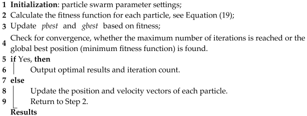
Section 3, a particle swarm optimization (PSO) method is introduced to determine the optimal weighting parameters of the controller, including the algorithm workflow, fitness function formulation, and implementation details.
Section 4 provides numerical simulations to verify the performance of the PSO-LQR controller. Finally, conclusions are drawn in
Section 5.
2. Modelling VBI System with General Boundary Conditions and Control Strategy
2.1. Modeling the VBI System and Governing Equations
When a vehicle travels over a bridge, its vertical motion is primarily influenced by road surface irregularities and bridge deformations. Road roughness characterizes the unevenness of the bridge deck and is generally modeled as a stochastic process represented by a power spectral density (PSD) function. Bridge deformation, on the other hand, results from both self-weight and vehicle-induced loads; however, the effect of self-weight is typically neglected in dynamic analyses, as it is assumed to be balanced out in the static equilibrium configuration. The deformation of the bridge is affected not only by the vehicle load but also by the boundary conditions of the bridge.
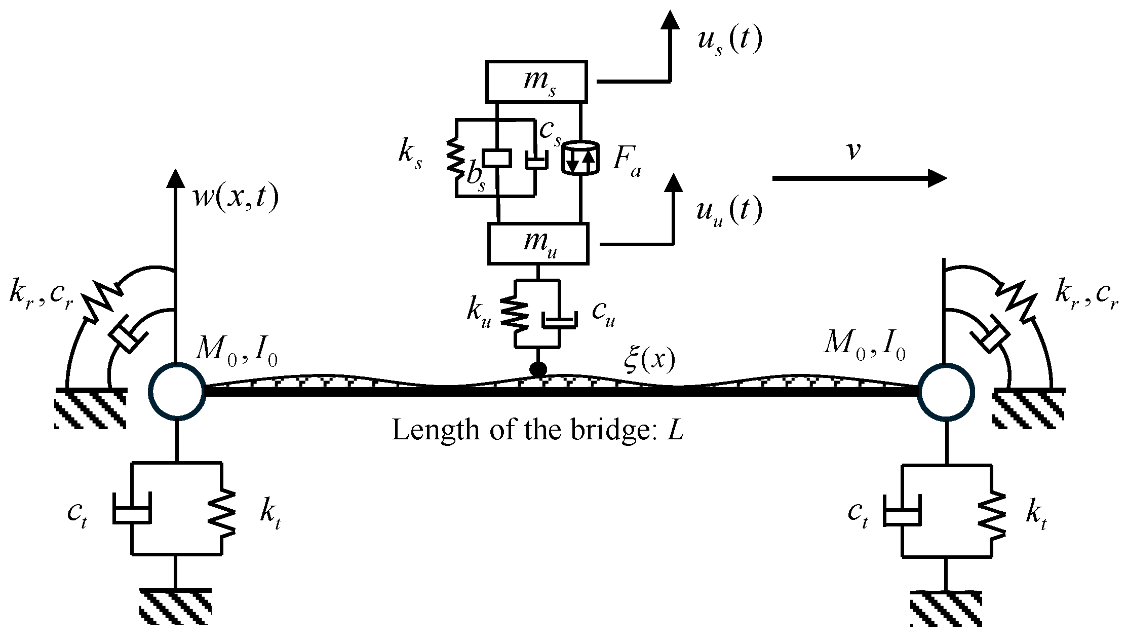
Figure 1 illustrates a Euler–Bernoulli beam model of a bridge with general boundary conditions at both ends and length
L. The translational constraints at the ends are denoted by
and
, while the rotational constraints are represented by
and
, respectively. A two-DOF quarter-car model, consisting of a sprung mass
and an unsprung mass
, travels over the bridge at a constant speed
. The vertical displacements of the sprung and unsprung masses are denoted by
and
, respectively. The interaction force between the wheel and the bridge surface is denoted as
, with
and
representing the tire stiffness and damping, respectively. The suspension system, which connects the sprung and unsprung masses, consists of a stiffness element
, a damping element
, and an inerter element
. Since this study investigates active suspension systems, the model also includes a control force
, which is generated by the actuator based on the output of a control strategy.
First, the road surface roughness is represented by a PSD function, and its spatial profile is calculated using the trigonometric series superposition method [
40] as
where
denotes the power spectral density of the road surface roughness;
represents the
specific frequency within the PSD;
is the frequency resolution; and
is the corresponding random phase angle. Taking the static position under the bridge’s self-weight as the equilibrium position, the governing differential equation for the vertical vibration of the bridge is given by
where
denotes the vertical displacement of the bridge;
is the density of the bridge;
represents the cross-sectional area;
is the bending stiffness; and
is the Dirac delta function,
indicating the instantaneous position of the vehicle or the point of vehicle–bridge interaction force. The coupling contact force on the right-hand side of Equation (2) is expressed as
The boundary conditions of the beam and the initial conditions of the coupled system are given by
Based on Newton’s second law, the equations of motion for the vehicle body are derived by
as well as the equations of motion for the unsprung mass
In summary, Equations (2)–(6) comprehensively describe the differential equations of motion, zero initial conditions, and boundary conditions for the coupled system shown in
Figure 1. The vertical displacement of the bridge vibration,
, can be expressed using the modal superposition method as
where
denotes the
i-th mode shape of the beam, and
is the generalized coordinate corresponding to the beam displacement. Substituting Equation (7) into Equations (2) and (6) yields the system of differential equations governing the motions of the bridge and the unsprung mass
Utilizing the orthogonality property of the mode shapes, Equation (8) is multiplied by
on both sides and then integrated over the domain from 0 to
L, resulting in
Let the generalized mass and stiffness corresponding to the
-th mode be denoted as
and
, respectively. Define the state increment vector as
. By combining Equations (5), (9) and (10), the controlled equations of motion for the vehicle–bridge coupled vibration system can be expressed as
where
denotes the system mass matrix,
the damping matrix, and
the stiffness matrix. Their detailed expressions are provided in
Appendix A.
Equation (11) can be expressed in the form of a differential equation as
where the state-space vector is defined as
, thus we have
2.2. Design of LQR Controller for VBI System
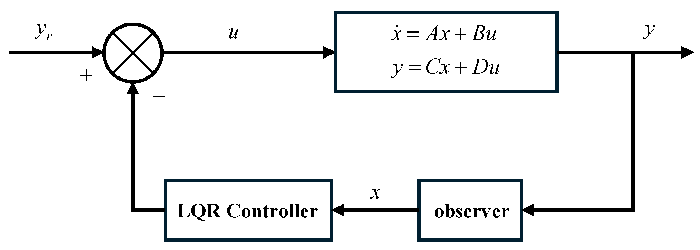
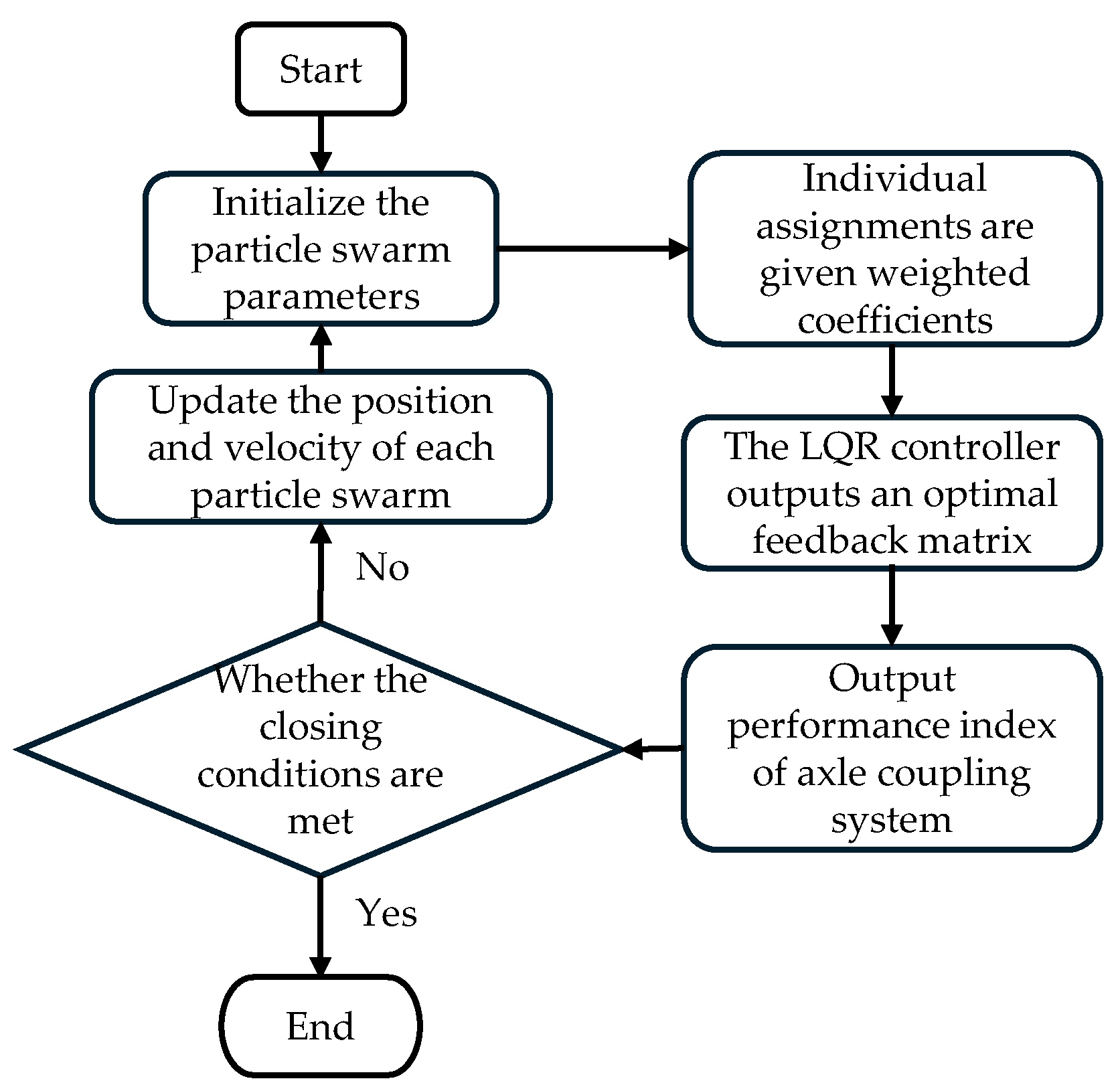
LQR control aims to achieve effective regulation of a given objective function with minimal control input, as illustrated in the flowchart shown in
Figure 2. Taking the vehicle active suspension system as an example, its primary goal is to enhance ride comfort while ensuring driving safety. Specifically, it seeks to reduce the vehicle body vertical acceleration and tire dynamic load as much as possible without increasing the suspension dynamic deflection. Therefore, this study employs an LQR control algorithm to actively adjust the actuator force of the suspension system.
The vehicle body acceleration
is used to represent ride comfort, while the relative displacement between the sprung and unsprung masses,
, characterizes he redundancy of the suspension moving space. The lateral deformation of the road surface is incorporated into the tire dynamic load calculation by defining the relative displacement between the tire and the bridge surface at the contact point,
. Consequently, the objective function is formulated as follows:
where
,
,
denote the weighting coefficients for the vehicle body vertical acceleration, suspension dynamic deflection, and tire dynamic travel, respectively, which influence the optimization and control of the target performance. The control output vector is defined as follows:
Combining with Equation (12), the above expression can be transformed into the state-space form as follows:
where
and
. By combining Equations (14)–(16), Equation (14) can be expressed in matrix form as follows:
where
.
The performance of the LQR controller is largely determined by the weighting coefficient matrix . In the multi-objective optimization design of control systems, selecting appropriate weighting matrices often presents a challenging parameter tuning problem. Traditional methods primarily rely on manual trial-and-error or exhaustive parameter scanning. Such heuristic search strategies suffer from dual limitations: on one hand, they lead to prolonged design cycles and significant resource consumption; on the other hand, due to the non-convex nature of the parameter space, experience-driven searches struggle to guarantee global optimality and may easily become trapped in local optima.
To address this control parameter optimization issue, this study proposes a PSO framework. By incorporating a dynamic inertia weight adjustment strategy and an elite particle preservation mechanism, the method develops an intelligent optimization algorithm with adaptive exploration–exploitation balance. The novelty of this approach lies in transforming the weighting coefficient selection into a convergent convex optimization problem, theoretically ensuring the asymptotic optimality of the LQR controller performance index within the Hilbert space.
2.3. Results of LQR Control
This study employs an ISD suspension in a parallel configuration, designs an LQR controller, and intends to optimize the control matrices using the PSO algorithm. Based on the VBI model established in
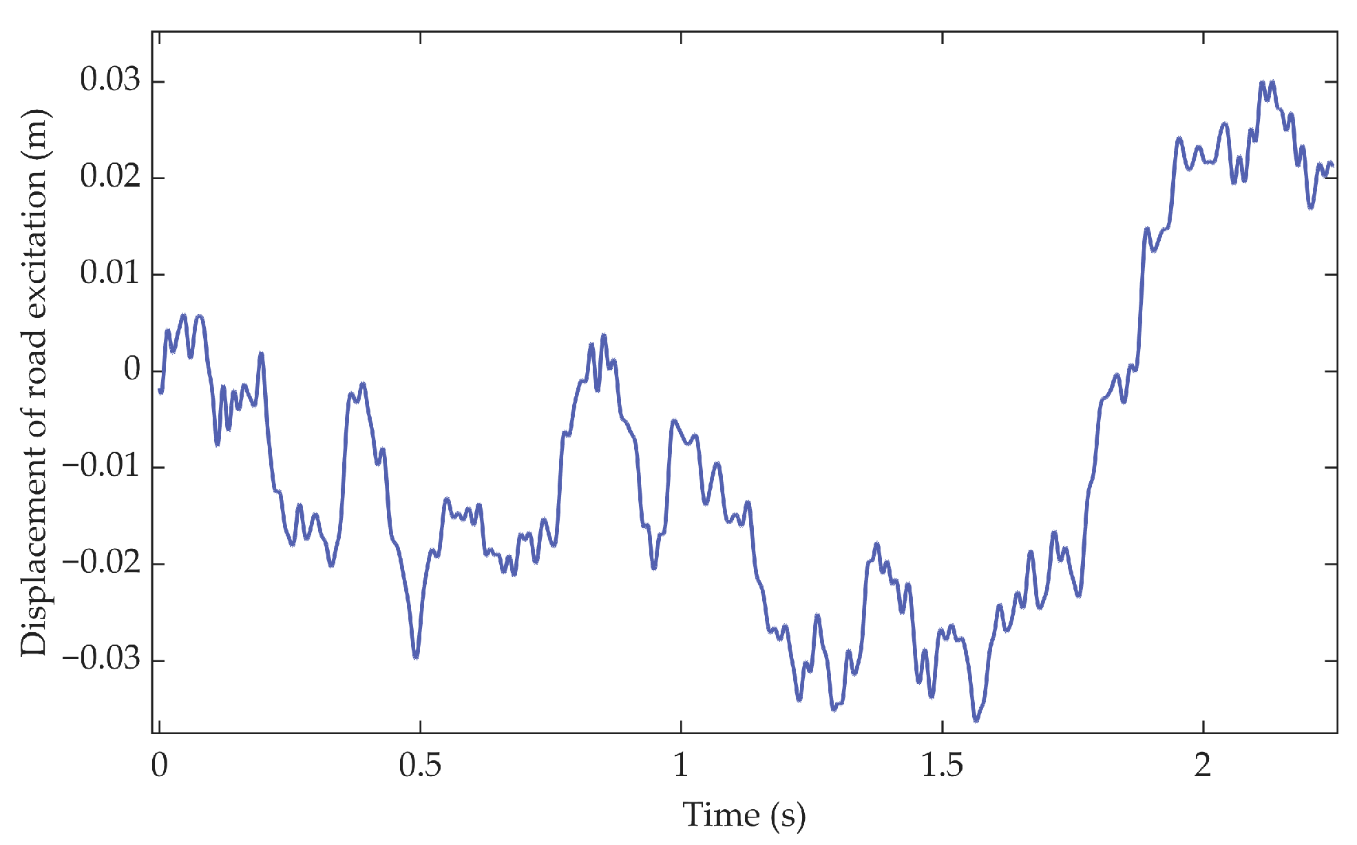
Section 2.1, the vehicle travels at 20 m/s on a Class C road surface. The excitation in displacement that acts on the vehicle is shown in
Figure 3. To verify the effectiveness of the proposed method, we first compare the passive suspension with the active ISD suspension, analyzing indicators such as the vehicle body acceleration in the vertical direction, suspension dynamic deflection, and tire dynamic load. In existing studies on bridge modeling, fixed-fixed or fixed-pinned boundary conditions are commonly adopted. However, these two cases represent only specific examples under general boundary conditions. While their advantage lies in computational simplicity, they are primarily suitable for simplified analysis of small-span bridges and exhibit limited generality. Therefore, this study employs a beam model with translational mass-spring-damper boundary constraints. This model allows for a more accurate representation of the actual boundary characteristics of bridge structures, thereby better aligning with the requirements of vehicle–bridge interaction dynamics and enhancing the engineering applicability and accuracy of the research. The parameters of the coupled vibration system are shown in
Table 1.
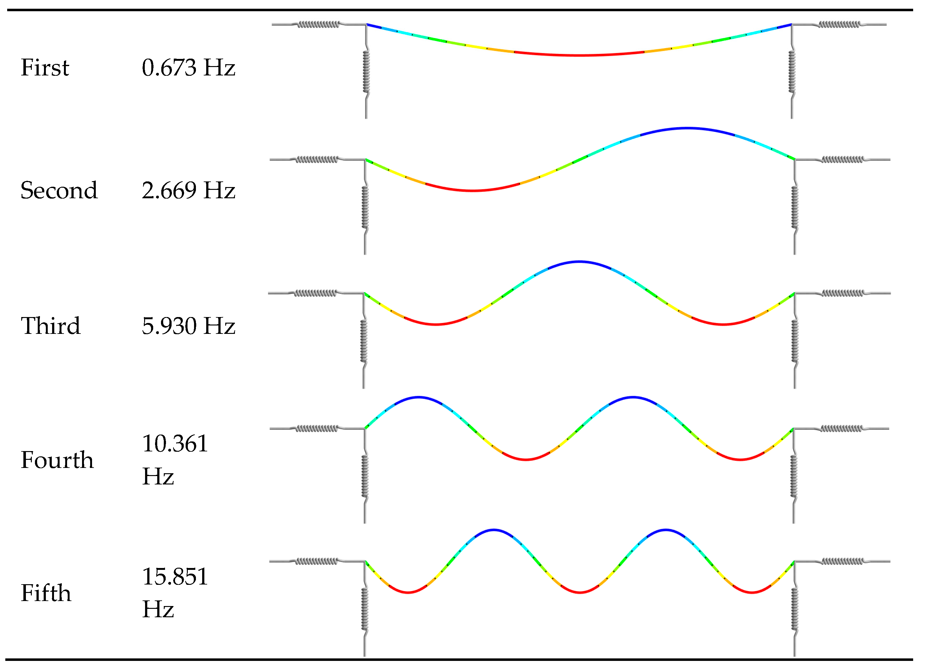
The VBI system is essentially a linear time-varying system, and obtaining its precise solution faces challenges in computational complexity and time-consuming. It is important to balance computational efficiency and solution accuracy. As illustrated in the previous section, the bridge modes are calculated using the finite element method (Ansys Workbench 2023R1), and the first five modes and frequencies are shown in
Figure 4. Theoretically, the computational accuracy of the modal superposition method increases with the number of modes included, but the computational time also increases significantly. Therefore, selecting an appropriate number of modes is crucial to avoid excessive computational cost while ensuring result accuracy.
On the other hand, human perception of vibration exhibits significant frequency dependence. Under most nonstationary driving conditions, the frequency range of vibration to which the human body is sensitive is mainly concentrated in the low-frequency region. The increase in vehicle’s speed leads to a broadening of the resonance frequency band of its suspension system; whereas under constant speed conditions, this resonance band is relatively stable. Therefore, we select the target frequency band, 0–25 Hz, for active control in this work. This frequency range effectively covers the main frequencies of occupant discomfort and the key resonance regions of the suspension system, thereby ensuring the effectiveness of the proposed control strategy in improving vehicle ride comfort. To this end, the first five modes of the bridge are used for calculation through finite element analysis and considering the frequency band requirements. This number of modes satisfies the analysis accuracy requirements for vibration responses within the 0–25 Hz while ensuring a faster computation.
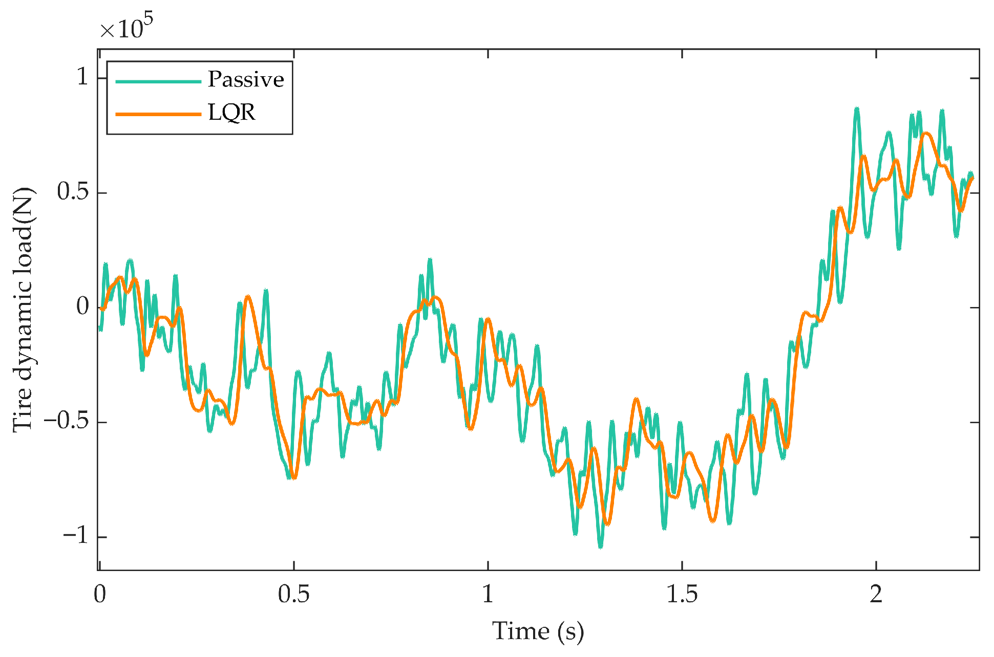
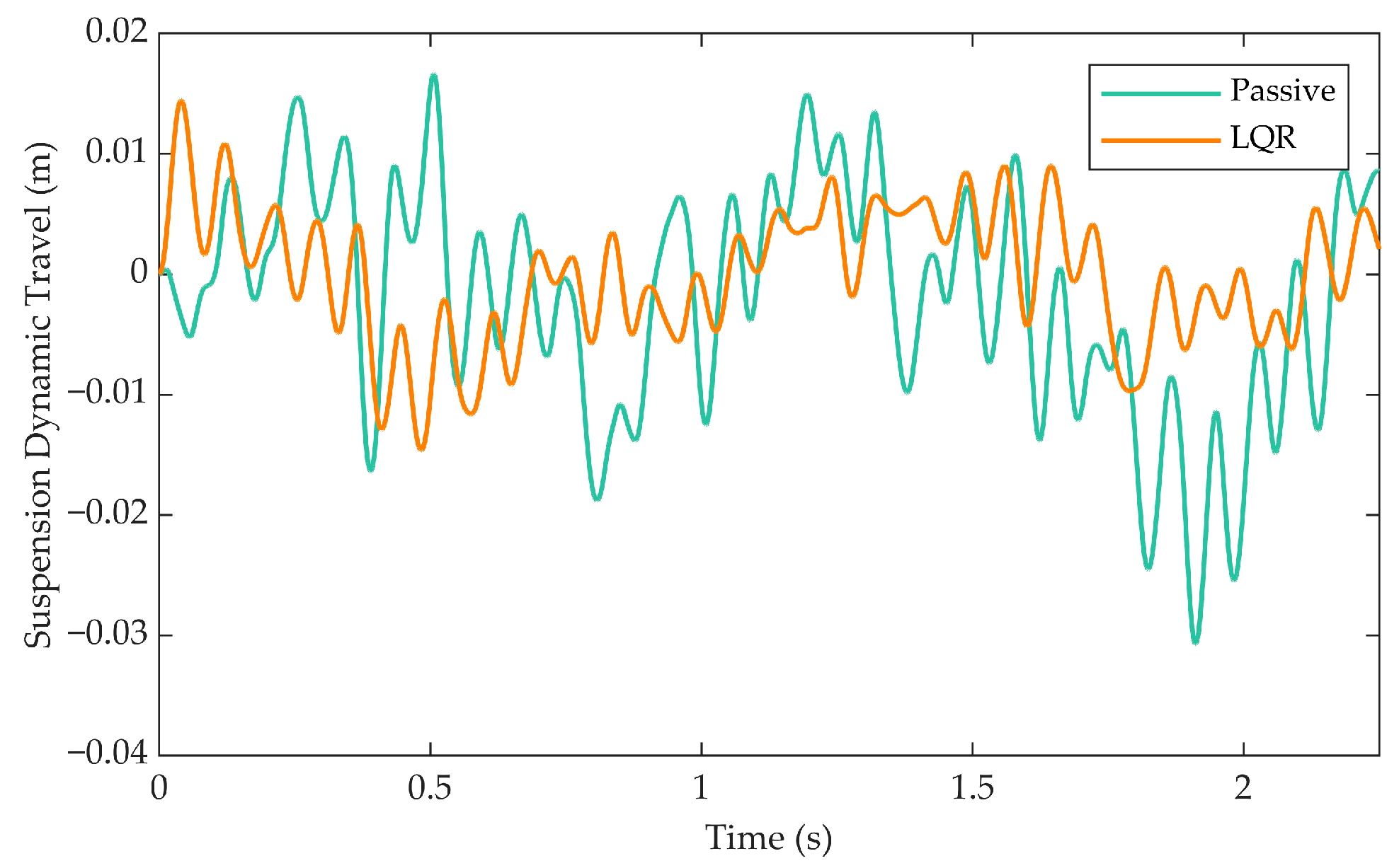
Figure 5,
Figure 6 and
Figure 7 show the comparison of key performance indicators between the ISD suspension with LQR controller and the passive system in the time domain.
Figure 5 and
Figure 6 shows that compared to the passive system, the LQR algorithm significantly reduces the amplitude of the tire dynamic load and the peak level of the vertical acceleration of the vehicle body. The reduction in tire dynamic load directly implies a decrease in the force exerted by the vehicle on the bridge, helping to mitigate the potential damage risk to the bridge caused by the vehicle loads. Simultaneously, the significant suppression of vertical acceleration of the vehicle body is a key factor in improving the ride comfort, indicating a clear advantage of the LQR control strategy in enhancing the driving and riding experience.
However, as shown in
Figure 7 due to the intervention of active control forces, the suspension dynamic travel of the LQR-controlled active suspension exhibits a trend distinct from that of the passive suspension. Notably, its peak value is significantly reduced compared to the passive system—this parameter is an important indicator in vehicle suspension systems, describing the maximum displacement range of the suspension during extension and compression. The reduction in suspension dynamic travel theoretically decreases the impact loads on suspension components, thereby mitigating the risk of mechanical failure or fatigue damage to some extent. Furthermore, it can be observed that the LQR-active suspension demonstrates improved convergence and stability, and its smaller amplitude vibrations contribute positively to enhancing vehicle ride comfort.
Based on the above discussion, it can be concluded that the application of LQR control strategy can effectively improve the vehicle’s performance even under the consideration of vehicle–bridge coupling effect. Its advantages are mainly reflected in significantly reducing the tire dynamic load (protecting the bridge structure) and suppressing the vertical acceleration of vehicle body (improving ride comfort). Although there is an increase in suspension dynamic travel, the resulting improvement in stability and fast convergence characteristics partially offset the potential risks.
Overall, the LQR control strategy demonstrates good potential for comprehensive performance improvement. However, the increase in suspension dynamic travel also reveals some room for optimization in the constraint conditions or objective function setting of this control strategy. Future research could consider introducing multi-objective optimization or constraint handling mechanisms to further suppress the increase in dynamic travel while ensuring performance advantages, achieving more comprehensive performance improvement.
4. Simulation Cases
4.1. Optimized Weighting Parameters for the Controller
The PSO algorithm parameters are set as follows: population size (number of particles) is 100, inertia weight is 0.8, maximum number of iterations is 100, learning factors are both 1.5. The selection range for the weight parameters is set as: . By executing the PSO algorithm with the above parameter configuration to optimize the objective function, a set of optimal weight coefficients is finally obtained: , , .This optimization process aims to systematically select the optimal weight distribution in the LQR controller to achieve the best balance among multiple performance indicators, thereby providing a theoretical basis and parameter foundation for subsequent vehicle–bridge coupled vibration control. The above parameter configuration balances the algorithm’s convergence speed and global search capability, helping to improve the comprehensive performance of the control system.
4.2. Reuslts Comparison
Figure 9,
Figure 10 and
Figure 11 show the dynamic performance indicators for the active suspension system with PSO-LQR controller, LQR-controller, and the passive suspension system.
Figure 9 in the Time Domain Diagram shows that the PSO-LQR based active suspension system significantly outperforms the LQR-controlled suspension and the passive suspension in terms of tire dynamic loads. Its peak load decreases from
before optimization to
, a reduction of approximately 12.7%.
Figure 9 in the Frequency Domain Diagram further indicates that the optimized suspension demonstrates a more stable dynamic load profile, with its amplitude significantly lower than that of the passive suspension beyond 12 Hz. This smoother response characteristic confirms the notable advantage of the PSO-LQR control strategy in enhancing vehicle ride comfort and reducing road excitation transmission. The overall response is smoother, indicating that the PSO-LQR control strategy has obvious advantages in improving vehicle ride comfort and reducing the transmission of road excitation.
Figure 10 in the time domain diagram shows that the vertical acceleration of the vehicle body after PSO is further reduced compared to the LQR suspension. The maximal acceleration decreases from 18.4143 m/s
2 to 9.7957 m/s
2, a reduction of approximately 46.8%.
Figure 10 in the frequency domain shows that the peak acceleration of the optimized suspension is significantly lower than that of the passive suspension beyond 5 Hz, with a more stable variation trend compared to the pre-optimized case.
Although the response approaches that of the passive suspension after 18 Hz, the PSO-optimized LQR active suspension demonstrates a notable reduction in body acceleration overall. This improvement effectively attenuates the vibrational intensity of the vehicle body, thereby contributing to enhanced driving and riding comfort. This improvement significantly reduces the vibration intensity of the vehicle body, contributing to enhanced driving and riding comfort.
Figure 11 shows that the suspension dynamic travel response after PSO exhibits better convergence and stability. Its transient oscillation is significantly weakened, and the amplitude is much smaller than that of the passive suspension system, and also improved compared to the LQR control. This result indicates that the PSO-LQR control strategy limits excessive suspension displacement, avoids hitting the suspension limit stops, while simultaneously considering ride comfort and handling stability.
To quantitatively evaluate the comprehensive performance of different suspension systems,
Table 2 lists the RMS values of the performance indicators for each system under the same road excitation. The results show that compared to the passive suspension, the PSO-LQR control strategy reduces tire dynamic load by 5.27%. Compared to the LQR control, the reduction is 3.04%. The vertical acceleration of vehicle body is reduced by 62.70% and 46.67%, respectively. The suspension dynamic travel was reduced by 68.2% and 45.1%, respectively. It can be concluded that the LQR active suspension optimized by the PSO algorithm demonstrates enhanced capability in reducing the dynamic interaction forces between the vehicle and bridge, as well as the vertical acceleration of the vehicle body. This contributes to improved ride comfort while mitigating potential damage to the bridge structure. Furthermore, the reduction in suspension dynamic travel effectively decreases mechanical fatigue risk, thereby extending the service life of the suspension system. All three performance indicators are significantly improved, effectively addressing the limitations of control algorithms that rely on empirical parameter tuning.
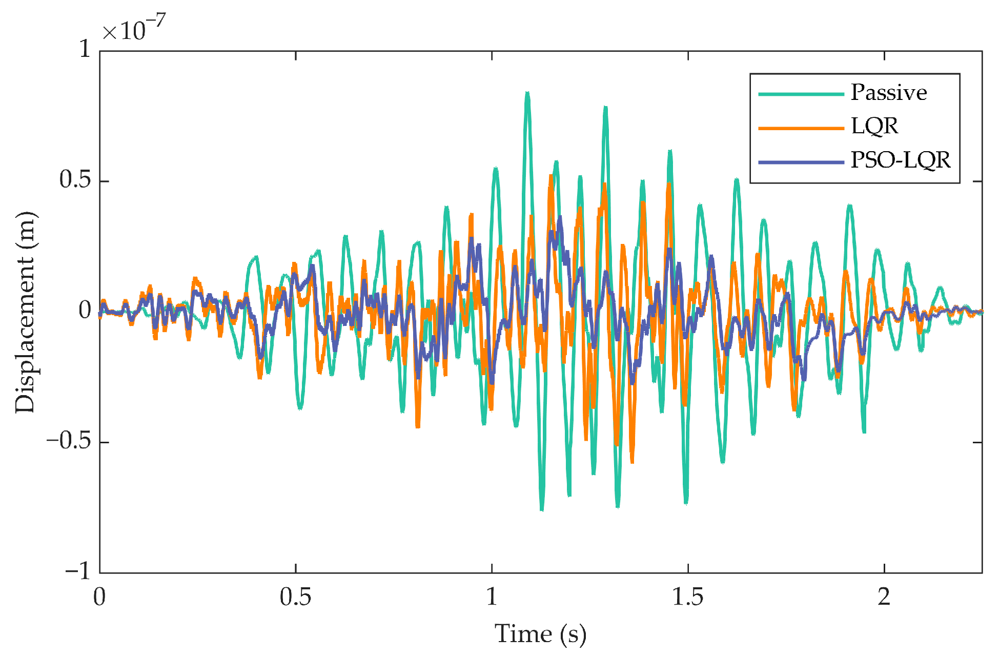
Figure 12 and
Figure 13 show the displacements of the bridge at the contact between the vehicle’s wheel and the bridge deck and at the midpoint of the bridge, respectively. Overall, the bridge displacement gradually increases as the vehicle travels on the bridge, and the vibration response tends to stabilize, and shows relatively obvious fluctuations. As the vehicle leaves the bridge, the vibration gradually attenuates and eventually stabilizes. According to
Figure 12, the peak value of bridge displacement at the wheel-deck contact point for the PSO-LQR suspension is
,which is about 48.14% lower than that of the passive suspension but about 20.45% higher than that of the LQR control strategy. To further evaluate the overall vibration suppression effect, the RMS value of the bridge displacement response is also calculated. The results show that the optimized bridge displacement RMS value is
, which is about 54.48% lower than that of the passive suspension
, and about 13.01% lower than that of the pre-optimization LQR control
.
The displacement response at the bridge midpoint in
Figure 13 is also quantified using RMS. The optimized value is
, which is about 60.39% and 33.45% lower than that of the passive suspension and the pre-optimization LQR control, respectively. These results consistently indicate that the PSO-LQR suspension system exhibits superior vibration suppression capability at these two key locations, with displacement amplitudes significantly lower than those of the passive suspension and the unoptimized LQR active suspension. This suggests that the proposed control strategy can effectively attenuate vehicle–bridge coupled vibrations and reduce the dynamic response of the bridge structure.
This vibration control effect is consistent with the reduction in tire dynamic load shown in
Figure 9, further validating the effectiveness of PSO-LQR control in improving vehicle–bridge dynamic interaction. The reduction in tire dynamic load directly reduces the local impact on the bridge deck, thereby significantly alleviating the transient vibration of the bridge structure.
In summary, by comparing multiple performance indicators of the PSO-optimized, LQR, and passive suspension systems, this study demonstrates that the PSO-LQR control strategy has significant comprehensive optimization effects in the vehicle–bridge coupled system. It outperforms the comparison systems in reducing tire dynamic load, suppressing the acceleration of vehicle body, and improving suspension dynamic travel, while effectively attenuating the vibration response at key bridge locations. The reduction in tire dynamic load further decreases the impact on the bridge deck, synergistically enhancing vehicle ride comfort and bridge structural durability. The results show that the proposed control method achieves a good balance among multiple performance indicators, possessing both theoretical and practical engineering application value.
5. Conclusions
This study addresses the issues of vehicle–bridge coupled vibration by proposing a PSO-LQR control system for an ISD active suspension. By establishing a VBI model considering general boundary conditions, multi-objective optimal control of the system’s performances was achieved. Compared to the passive suspension, the PSO-LQR control strategy reduces tire dynamic load by 5.27% and vertical body acceleration by 40.98%, while effectively suppressing the fluctuation amplitude of suspension dynamic travel. The RMS values of dynamic displacement responses at key bridge locations decrease over 50%, indicating that this method significantly mitigates the risk of fatigue damage in bridge structures. The PSO algorithm successfully addresses the global optimization of LQR weighting matrices, overcoming the tendency of traditional trial-and-error methods to converge to local optima, thereby enhancing the convergence and stability of the suspension system. The proposed strategy not only improves vehicle ride comfort but also reduces the dynamic impact of vehicle loads on the bridge deck, offering technical support for extending the service life of bridges. The theoretical framework and optimization methodology presented in this study provide new insights into the intelligent control of complex coupled vibration systems. Interdisciplinary collaboration will be essential to promote their large-scale application in smart transportation infrastructure.
Despite the promising results, it is important to acknowledge the limitations of this study. The validation of the proposed PSO-LQR control strategy is currently based on a simulation model. While the VBI model was established with careful consideration of general boundary conditions and system dynamics, a purely simulation-based approach inherently lacks the ability to capture all the intricacies of a real-world environment, such as unmodeled nonlinearities, sensor inaccuracies, and practical implementation delays. These factors could influence the controller’s performance in practical applications. Therefore, the findings presented herein should be interpreted within the context of a simulation study. To bridge this gap, our future work will focus on experimental validation, including hardware-in-the-loop (HIL) testing and field experiments with a scaled or full-scale prototype, to further verify the efficacy and robustness of the proposed control system under more realistic conditions.
