Abstract
The advancement of onshore and offshore wind turbines depends on the experimental validation of new technologies, novel component designs, and innovative concepts. However, full-scale models are typically very expensive, have limited functionality, and are difficult to adapt to diverse research needs. To address this shortcoming, this article presents the design of a low-cost, modular 3D-printed small prototype of a wind turbine. It includes a multi-hollow platform for marine environments configuration and stabilization, the turbine tower, and three blades with active pitch control, not always included in wind turbine prototypes. The modular tower design allows for easy height extensions, while the rotor incorporates custom blades optimized for the prototype geometry and experimental setup. Tests were conducted to evaluate the system’s operational response and verify the proper functioning of the assembled components at various wind speeds and blade pitch angles. The results confirm that the rotor speed with the prototype’s onshore configuration is highly pitch-dependent, reaching a maximum efficiency of approximately 5°. The tower displacement, measured with an IMU, remained within a narrow range, oscillating around 2° and reaching up to 4° at higher wind speeds due to elastic deflections of the PLA structure. These results, consistent with the prototype scale, validate its usefulness in capturing essential aerodynamic and structural behaviors of the wind turbine. They also demonstrate its relevance as a new tool for experimental studies of wind turbines and open up new research, validation, and control possibilities not considered in previous developments by incorporating blade pitch control.
1. Introduction
The planet is immersed in a continuous process of evolution, and global energy generation is one of them. Energy demand is constantly increasing due to rising human needs, population expansion, industrialization, and technological progress. Meeting these needs has become a priority and a challenge, placing great importance on sustainable solutions as viable alternatives. Fossil fuels, primarily coal and natural gas, have been the main sources of energy until recently, but they produce adverse effects as they contribute to greenhouse gas emissions and climate change, causing serious environmental impacts such as air and water pollution and biodiversity loss [1,2].
To address these challenges, renewable energy sources such as wind, solar, hydroelectric, and geothermal energy are used, and these solutions have experienced significant expansion in recent decades. Using these natural resources presents notable advantages, as they are abundant on the planet and produce few or no emissions during operation [3]. Due to these characteristics, they can help mitigate the negative effects that polluting procedures have on life and the planet. Furthermore, they are less expensive and competitive compared to fossil fuels. Recent data shows that most new renewable energy generation projects are now cheaper than traditional alternatives [4,5].
The growing need for renewable energy sources has driven the development of more efficient and adaptable technologies. Among them, wind energy has proven to be a suitable option due to advances in turbine design, improved control systems [6] and thanks to the reduction in manufacturing, installation and maintenance costs [7]. All this has made wind energy today one of the largest sources of renewable energy [8]. In search of the best locations for wind turbines, production has shifted to marine areas, both on the coast (bottom offshore wind turbines) and offshore (floating offshore wind turbines, FOWT). The latter find better conditions in deep waters, with more consistent and stronger wind flows, more available space, and less visual and noise impact [9,10].
These systems have experienced massive expansion in installed capacity over the past few decades [11]. By the end of 2024, the cumulative global installed wind power capacity reached approximately 1136 GW, of which 83 GW corresponded to offshore wind. Figure 1 shows the percentage distribution of this cumulative offshore capacity by country, with China, the UK, and Germany together accounting for 80.4%. In terms of annual additions during 2024, approximately 109 GW of new onshore wind and 8 GW of new offshore wind were installed [12]. Offshore deployments are expected to increase, with predictions exceeding 500 GW by 2050, reflecting the maturity of floating offshore wind turbines (FOWTs) [13].
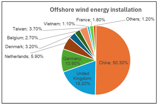
Figure 1.
Percentage distribution of worldwide cumulative offshore wind energy capacity by country (Data source: [12]).
Marine wind turbines are classified into two groups according to their foundation type: anchored to the seabed and floating ones. This categorization has implications for the water depth and distance from the coast where they can be installed [14]. The first group is located in shallow waters, with fixed-bottom foundations up to approximately 60 m deep. These structures commonly include monopile foundations, which consist of large steel tubes inserted into the seabed, and jacket structures, which consist of grid structures supported by several piles.
On the other hand, floating offshore wind turbines (FOWTs) are installed in deeper waters (more than 60 m), where fixed foundations cannot be installed due to the coastal slope. According to the structure of these turbines, which are anchored to the seabed by mooring lines to prevent drift, three types can be identified. The spar buoy platform is characterized by a long, cylindrical tower, which provides stability by ballast and is connected to the seabed [15]. The second group corresponds to Tension Leg Platforms (TLPs), which are designed as structures with reduced vertical movement achieved with tensioned tendons anchored to the seabed [16]. In the third category are semi-submersible platforms as well as barge-type platforms, popular designs that present greater stability in different marine conditions and are suitable for large wind turbines (LOWT) with high production capacity [17].
The large size of FOWTs and the harsh environment in which they operate have prompted research into electrical stability and grid connection, energy tracking and pitch control strategies, platform stabilization, wind prediction, and vibration reduction [18,19,20]. Another important aspect to consider is the design of the components of these large turbines [21]. The structure provides the support and functionality necessary for the device’s normal operation.
For the process of perfecting the various parts of a wind energy device, simulations, isolated tests, and more complete representations of this device in software are usually run. While numerical simulations for refining the design remain indispensable, it is necessary to advance in the analysis and study of the wind turbine in physical models that integrate elements of reality. The use of pilot wind turbines for testing, demonstrations, or research is a necessary step to bring solutions closer to commercialization [22]. The use of small-scale prototypes allows not only the structural representation of the wind turbine, but also the incorporation of the corresponding electronics and control systems, and the testing of the operation of these devices.
Recent works have addressed these gaps by using experimental setups with wave-tank [23], additive manufacturing [24], and modular platforms [25]. Although these approaches are highly relevant, some challenges are associated with scaling and cost in wave-tank testing, reduced mechanical strength of 3D-printed parts, and structural integrity challenges in modular platforms. For example, Bianchini et al. [26] reviewed the current status of small wind turbine prototypes, discussing some of the limitations. One of the most crucial ones is the lack of active pitch implementation due to its complexity, something that we address in this study. In [27], the research highlights the viability of low-scale wind turbines to be integrated into buildings for energy production, taking advantage of its modularity, reduced cost and simple structure.
Similarly, several studies [28,29,30] have shown that computer-aided design (CAD) software and 3D printing can be successfully used for prototyping wind turbine blades and other small-scale components of wind turbines. The use of these tools also facilitates aerodynamic model analysis, design refinement, and experimental testing. In this regard, most of the work is conducted in the laboratory or on a small scale, but it offers promising results that can be extrapolated to other levels to improve the mechanical performance and structural design of commercial wind devices.
Some small-scale wind turbine prototypes are reported in the literature, generally focusing on stall or yaw control. In addition to the limitations of all pilot wind turbines, such as high manufacturing costs, lack of modularity, and insufficient functionalities, they are rarely built to allow active pitch control due to the complexity of the elements required for their implementation [26,31,32]. This limitation restricts their ability to reproduce the aerodynamic and operational characteristics of large-scale wind turbines.
To address the need to optimize the design and configuration and improve the performance and functionality of the wind system, this work aims to design a small-scale wind turbine that is compact and easily modifiable so that the analysis of its operation allows the transfer of study conclusions to real turbines.
To this end, the mechanical design of a prototype onshore/offshore wind turbine was performed, focusing on its structural topology and geometry, prioritizing the versatility of the system for modular modifications. Furthermore, the prototype addresses a common limitation in small-scale wind turbine models by incorporating blade pitch control as an additional degree of freedom. CAD software (FreeCAD 1.0) was used for geometric modeling of the device, while manufacturing was achieved using 3D printing.
The main contributions of this work can be summarized as follows:
- -
- Design of a small-scale land-based/floating wind turbine prototype, composed of mechanically coupled parts, suitable for laboratory experimentation.
- -
- Development of a modular system that facilitates reconfiguration and resizing. This modularity allows for rapid assembly, disassembly, and replacement of parts, without the need to redesign the entire structure.
- -
- Integration of blade pitch motion into the prototype, something not very common, allowing for the implementation of pitch control strategies in addition to rotor speed regulation.
- -
- The design allows for the adaptation of two motor/generators of different sizes and capacities, allowing the assembly to be used as systems with different power ratings (capacities).
- -
- Experimental study of the modular prototype by acquiring key operational variables, including voltage, rotor speed, and tower pitch angle, the latter serving as an indicator of structural vibrations.
The manuscript is organized into different sections that describe the mechanical design proposed in this work. Section 2 presents the methodological approach used in the development of the wind turbine prototype. Section 3 details the design of each component of the wind device, considering both the geometry of the parts and their assembly feasibility. Section 4 presents the model validation based on data acquired from the prototype. Finally, Section 5 summarizes the main conclusions and potential directions for future research.
2. Methodology
The wind turbine prototype design was developed using a component-based, modular approach, aiming to ensure scalability, reconfigurability, and flexibility. Each component was designed as an independent module to facilitate rapid replacement and allow modification and experimentation with different configurations and geometries, without requiring a complete turbine redesign.
The methodology used in this study aligns with a systematic process often applied in physical system design. Initially, background research was performed and essential operational requirements for the system were defined, followed by the conceptual design stage and CAD modeling of each component. Then, the models were then fabricated using 3D printing technology and assembled to evaluate modularity, compatibility, and functionality, checking how well the parts fit together and how easily the system could be reconfigured. Finally, experimental validation was performed to assess the operational behavior of the prototype under controlled wind conditions. This approach enabled iterative improvements and is consistent with conceptual design methodologies for mechatronic systems, particularly those applied to wind turbine prototypes [33].
The modules designed for the small-scale wind turbine model are described below:
- Blades: Three blades spaced 120° apart are integrated into the horizontal axis of the wind turbine. The three-blade geometry features a 15° curvature along its length to allow for different angles of attack as the blade changes its pitch motion. The choice was based on the aerodynamic behavior of small-scale turbines at low Reynolds numbers, where blade curvature improves the lift-to-drag ratio and compensates for the lower aerodynamic efficiency [34].
- Tower: A segmented tower was implemented to allow height adjustments and facilitate transport and reconfiguration, consistent with recent reviews highlighting modular architectures as effective for exploring structural adaptability in offshore wind turbine prototypes [35].
- Platform: The barge platform is a component where the tower is attached and allows the wind turbine to be adapted to an offshore configuration. Additionally, hollows have been implemented in the platform to simulate aspects of flotation and conduct stability experiments when necessary.
- Connection system: A bayonet-type connector was selected to join the tower segments, as it provides torsional rigidity and ease of assembly/disassembly.
The prototype was developed with a focus on modularity in key elements such as the blades, rotor, and tower. Three-dimensional representations of these geometric components were created using CAD software (FreeCAD 1.0) to allow for the evaluation of different configurations.
From the digital model, two physical prototypes were manufactured using fused deposition 3D printing (FDM). Printing was carried out on a Bambu Lab X1C printer (Bambu Lab, Shenzhen, China) using generic 1.75 mm PLA material. This filament was chosen due to its availability, low cost and environmental friendliness, as well as its good dimensional accuracy under optimized 3D printing parameters, making it suitable for iterative prototyping [36].
Indeed, PLA has proven to be an ideal material for the initial phase of prototyping, thanks to its easy and stable printing, as it does not warp upon cooling, allowing for highly detailed parts with good surface finishes from the first attempt. Its low cost and biodegradability make it suitable for rapid iteration in research environments. However, it has some mechanical limitations, such as fragility and low impact resistance, which can lead to cracking under sudden stress or continuous tension. It also has low thermal resistance (softening around 60 °C). Nevertheless, under the operating conditions of this study and the proposed future research, these conditions, which might deform the model, are not expected to occur.
Some printing parameters used for this work were:
- -
- Nozzle temperature: 220°
- -
- Bed temperature: 55°
- -
- Layer height: 0.2 mm
- -
- Infill density: 15%
- -
- Print speed: 100%
- -
- Assembled parts were designed with a dimensional tolerance of 0.25 mm, enough to ensure proper fitting of bayonet connectors, blades, tower and motor housing.
The modular components are assembled manually to verify ease of construction and compatibility with the electrical components integrated into the prototype.
The two small-scale models assembled are one with a 502 mm diameter rotor and the other with a 438 mm diameter, with the tower segments being changed for each device.
The smaller model was used for initial experimentation. Variables such as voltage, rotor speed, and tower angular displacement were measured in a fixed-base configuration.
The prototype is equipped with sensors to capture data and a microcontroller, an Arduino NANO board (Arduino, Somerville, MA, USA), to compile it. The Arduino device is located on the tower, ensuring that the integrated optical sensor points to the plane of the blades swept area to measure their intersection and calculate the rotational speed. In addition, an Inertial Measurement Unit (IMU) mounted on top of the tower is used to detect tower movement while the wind turbine is operating. During the experiments, ambient conditions were also monitored, including airflow (measured with an anemometer) and temperature.
The electromechanical system includes a small DC motor connected directly to the rotor. No external loads were applied during this testing phase, as the objective was to observe the system’s natural response and verify component assembly, rather than optimize power output. Testing focused solely on structural response and functionality, not power optimization or full aerodynamic characterization.
The experiments were conducted in a laboratory environment at 26 °C, with steady wind speeds of 3.7 to 5.5 m/s.
The design and testing strategy adopted in this work follows the rationale of recent experimental methodologies for floating offshore wind turbines, which emphasize the importance of scaled physical models to validate structural responses before advancing to more complex environments [37].
3. Component Topology and Geometry
3.1. Rotor Blades
A customized NACA 4412 airfoil was used as a basis for designing the blade geometry. This choice was motivated by the widespread use of airfoils from this series in small-scale wind turbine research, as they provide reliable aerodynamic performance at low wind speeds with acceptable lift-to-drag characteristics [38]. The blade design incorporates a geometric twist that progressively decreases from 15° to 0° from root to tip, improving aerodynamic response across the span by locally adjusting the angle of attack.
The blades were designed to attach to the hub with adequate clearance from the tower, facilitating their replacement without the need for specialized tools.
Two sets of blades were manufactured. The first extends 231 mm from the blade root connection hole to the tip (Figure 2a). For the second, smaller configuration, the blades have a length of 199 mm (Figure 2b). The second configuration, assembled with the remaining wind turbine components described below, was designed considering the spatial constraints of the experimental facilities. In particular, this configuration was sized to fit into a wind tunnel and wave tank (0.65 m high and 0.55 m wide) [21], while maintaining geometric consistency with the rotor and the overall system. This ensures compatibility with future experimental work. It should be noted that the blades were not aerodynamically optimized; the goal was to reproduce a representative rotor geometry on a small scale suitable for modular prototyping.
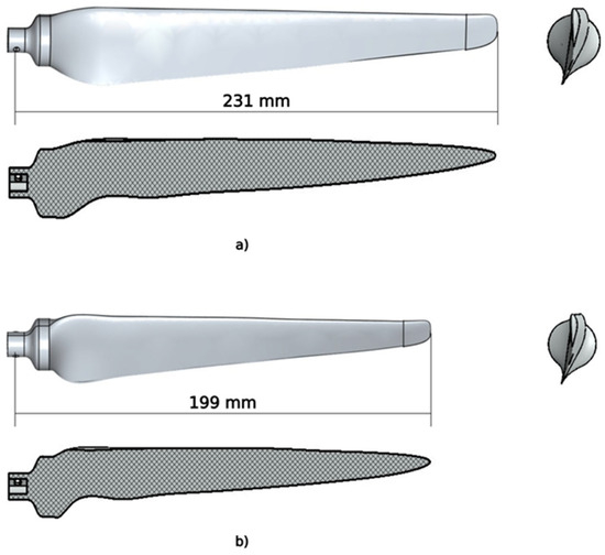
Figure 2.
CAD model of the blade with front, side, and section views: (a) First configuration; (b) Second configuration.
3.2. Nacelle and Supports
The nacelle incorporates a prefabricated 90° bevel gear system, which acts as the main mechanical transmission of motion between the rotor and the generator. The horizontal shaft, aligned with the rotor axis, transfers rotational motion through the bevel gears to a perpendicular vertical shaft connected to the generator. The gear system maintains a 1:1 transmission ratio, directly connecting both gearbox shafts without altering the angular velocity. This system was chosen to preserve the kinematic behavior of the rotor, maintaining the mechanical simplicity and robustness necessary for small-scale operation in a laboratory. Bevel gears are commonly used in wind turbines and industrial systems for their ability to transfer motion between perpendicular shafts while maintaining efficient compactness [39].
This mechanism connects to the blade connecting piece through the blade-hub connector, which also allows blade pitch adjustment. This arrangement allows the angular position of the blades to be modified with a simple actuating lever, facilitating preliminary studies of pitch variation. Figure 3 illustrates the transmission mechanism, showing both the front (a) and side (b) views, which constitute the central component of the nacelle.
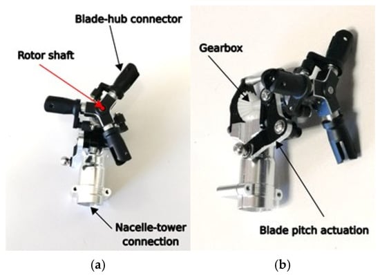
Figure 3.
View of the motion transmission mechanism: (a) Frontal view; (b) Lateral view.
To visualize the integration of the blades, Figure 4 presents a CAD model of the three-blade rotor mounted on a simplified representation of the hub. This highlights the modular design strategy, which facilitates assembly, disassembly, and possible reconfiguration of the rotor system without the need to redesign the hub.
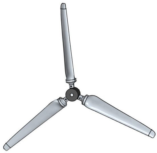
Figure 4.
CAD model of the three-blade rotor.
3.3. Modular Tower
The tower was designed as a segmented modular structure, composed of tubular sections connected by a quarter-turn bayonet mechanism, reinforced with a 3D-printed pressure coupling ring. This configuration allows the height to be modified by replacing the top segment, adapting the structure to different experimental scenarios, or using a different wind turbine model. Modular tower concepts have also been addressed in the literature; for example, in [9], the authors review advances in tower design, including segmented architectures, emphasizing structural integrity, scalability, and adaptability in offshore and onshore towers.
The use of bayonet connectors was due to their ability to provide torsional rigidity while ensuring rapid assembly and disassembly. The lower tower segment is designed to fit onto the platform and accommodate a commercial 36 mm diameter direct current (DC) motor. Its geometry is shown in Figure 5. The height is set at 117.5 mm with an outer diameter of 13 mm. The tower segment mounting mechanism is located at the top, where the internal path of the quarter-turn hole and the external rail for the connecting ring can be identified. The tower base therefore features an adjustable system that allows it to be attached to different test stands, such as floating platforms or onshore wind energy benches. The top section features a connection system to other segments to modify the overall tower height.
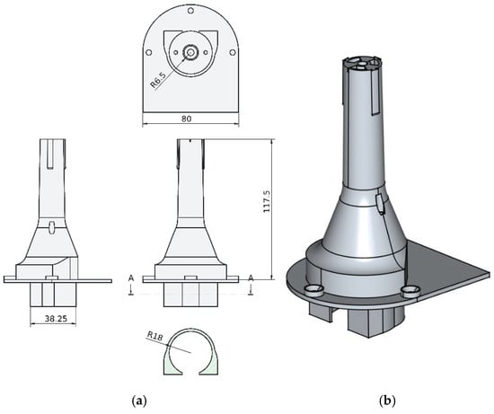
Figure 5.
Bottom section of the tower: (a) Drawing; (b) 3D isometric view.
To complete the tower assembly, the upper section is connected. This segment extends the tower’s height and can be designed with different geometries to modify the wind turbine’s topology and allow for the coupling of components using other arrangements, thus creating a unique model.
In this paper, two wind turbine model configurations of different tower heights and blade sets were designed to demonstrate the flexibility of this approach.
In the first wind turbine configuration, the prototype was built with a taller tower and 231 mm blades. In this case, the top section (Figure 6) directly connects the vertical drive shaft to the motor using an aluminum bar inside the tower to transfer angular rotation from the gear shaft.
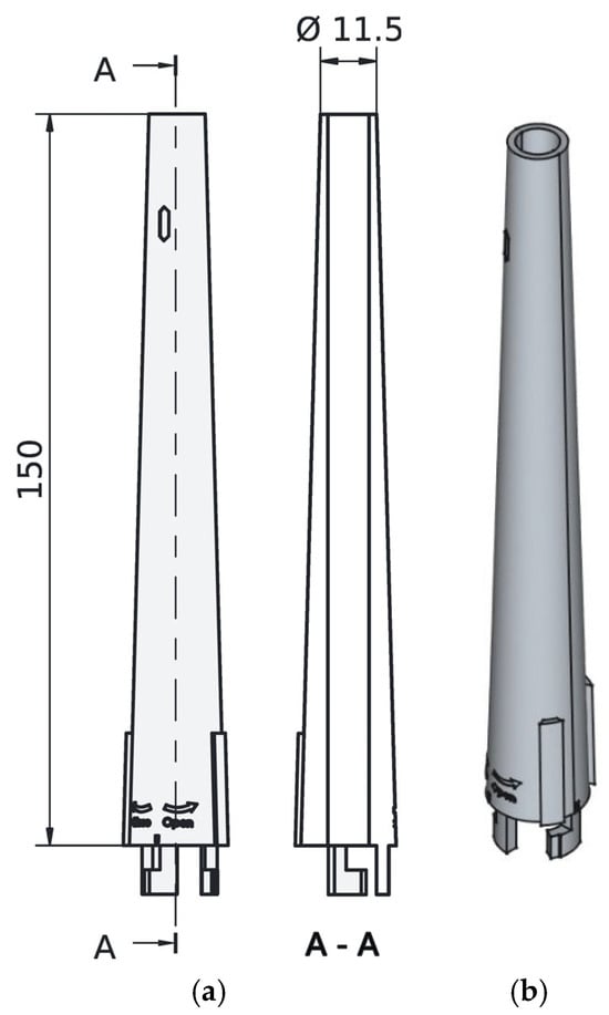
Figure 6.
Upper section of the tower for the first configuration: (a) Drawing and section view (A-A); (b) 3D isometric view.
In the second WT configuration, the prototype employed a shorter tower and 199 mm blades. Here, the upper segment (Figure 7) was designed as an extension that incorporates a motor housing on top of the tower, allowing direct coupling to the gearbox. This new design reduces shaft alignment limitations and provides greater flexibility for testing a smaller motor-generator in the nacelle area.
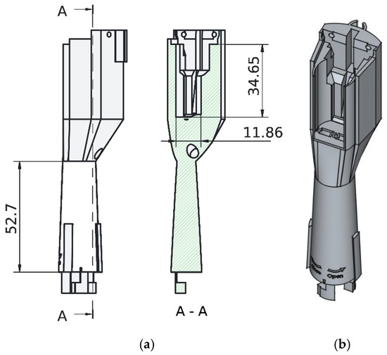
Figure 7.
Upper section of the tower for the second configuration: (a) Drawing and section view (A-A); (b) 3D isometric view.
The structure that houses the motor and connects to the gearbox mechanism is shown in Figure 8a,b. This module was designed to attach a generic 5 V DC motor to the top of the tower and connect to the mechanical transmission module that supports the rotating parts of the wind turbine. Additionally, a top bracket was included to locate and attach a servomotor used to control the blade pitch angle. The gearbox and generator are coupled by a 3D-printed shaft (Figure 8c,d), which transmits rotational motion. This component was printed in PLA with a fine mesh structure and 80% infill, providing adequate strength to withstand the stresses that may arise during normal wind turbine operation.
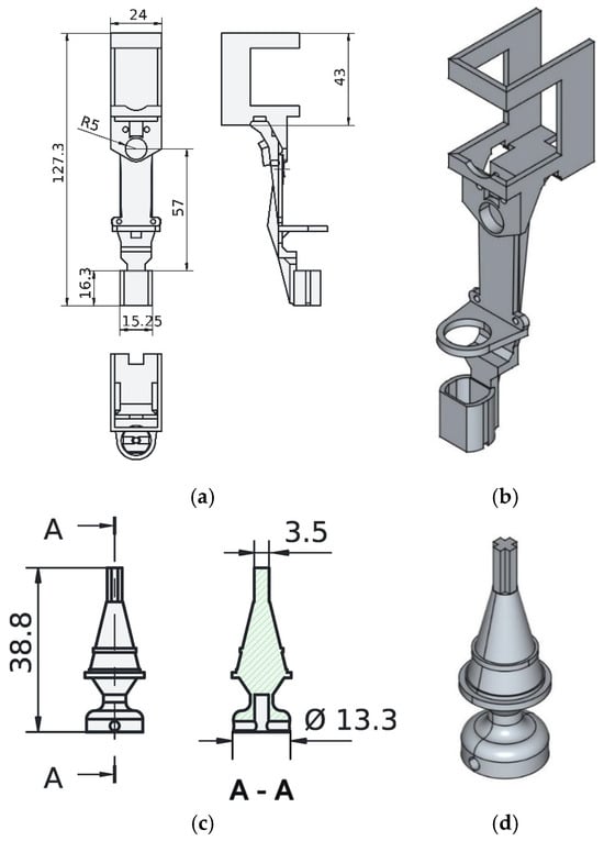
Figure 8.
Motor-gearbox housing structure for the second configuration: (a) Drawing; (b) 3D isometric view; (c) Drawing and section view (A-A) of the motor-gearbox connection axis; (d) 3D isometric view of the axis.
The two tower segments (base and top) are joined by a quarter-turn bayonet joint (Figure 9a), where the bottom of the upper tower segment is attached to the top of the lower segment by a connecting ring (Figure 9b). This system was selected to strengthen the connection between the two segments and provide rigidity to the tower structure.
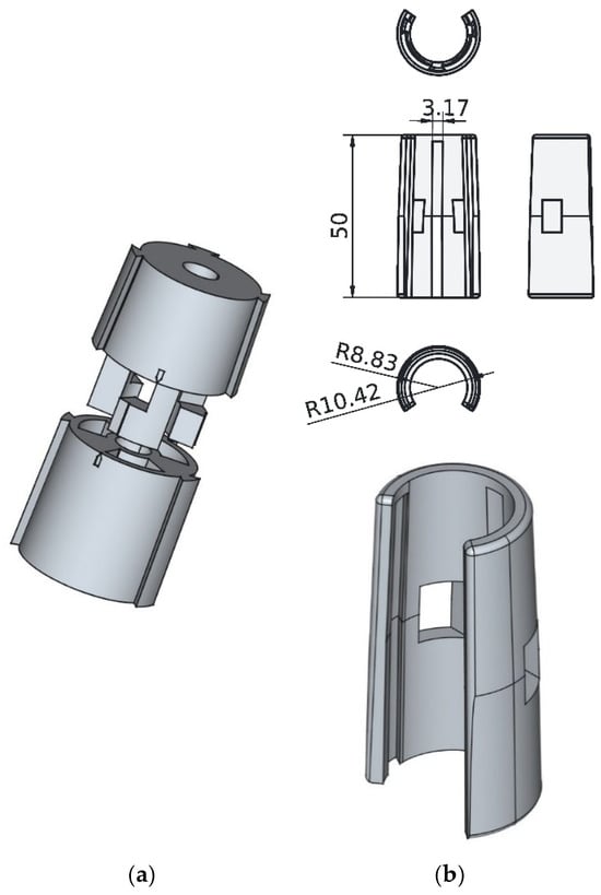
Figure 9.
Junction system: (a) Quarter-turn bayonet system; (b) Connection ring.
3.4. Base Platform
The platform is designed as a robust barge that provides stable support for the tower. The WT platform design is intended to be suitable for future studies of both onshore and floating turbines, so it has been equipped with features that can facilitate the analysis of both its stability and hydrodynamics.
Two key factors were taken into account when defining the platform size. First, the limitations of the facilities where the prototype will be experimentally tested, and second, the height of the platform to ensure its buoyancy. Based on these criteria, the platform geometry shown in Figure 10 was constructed, in which some of its main dimensions are specified. It is a rectangular barge-platform measuring 240 × 310 × 60 mm. The vertical length was set at 60 mm, based on the total mass of the wind turbine, to ensure that submersion does not exceed 30 mm. It also includes a space to securely house the electronic components inside.
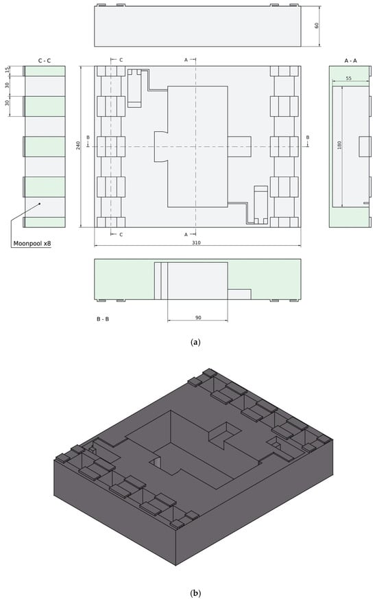
Figure 10.
Wind turbine platform design: (a) Drawing and section views (A-A, B-B, C-C); (b) 3D isometric view.
It has eight 30 mm long square moonpools or hollows, evenly distributed at the front and rear. These hollows are designed to regulate wave-induced forces, thereby reducing wave thrust on the structure and contributing to the platform’s overall stability. While the hydrodynamics of a platform with these hollow sections is a complex problem requiring specific analysis, previous studies have shown that they can effectively mitigate wave-induced motions on floating structures [40].
After all the components of the wind turbine prototypes were designed, they were assembled. The fully assembled wind system, including all its subsystems, is shown in Figure 11a. For a better understanding of the overall structure, an exploded view of the elements is presented in Figure 11b. This illustration helps visualize how the subsystems and individual parts are organized and integrated into the final assembly. Using the different component configurations designed, such as smaller or larger blades, and the upper tower section to house the generator above or below the structure, two different wind turbine models can be built.
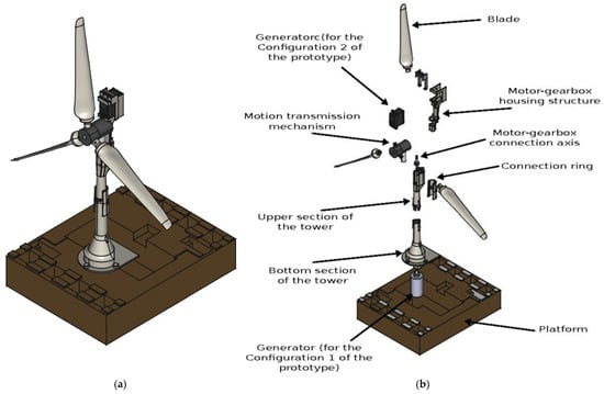
Figure 11.
Design of the wind device: (a) Fully assembled floating offshore wind turbine prototype; (b) Exploded view showing the structural components.
The dimensions of the assembled physical models are summarized in Table 1 for each wind turbine version designed. It can be seen that the size and configuration can be varied to easily create different models with the modular structure.

Table 1.
Geometric dimensions of the wind turbine models.
4. Results from Experimental Tests
The experimental evaluation focused on verifying the operational capability of the prototype wind turbine (using the second tower configuration) under controlled wind conditions. Available sensors were used for data acquisition to assess its performance, focusing on voltage/power generation. The experiments were conducted using a land-based wind turbine with a fixed platform. Data were captured in real time for visualization and analysis, with wind speeds as the external input to the system. The purpose of this initial study is to validate the design and integration of the subsystems (rotor, pitch mechanism, sensors, and modular tower) and assess whether the prototype reproduces the expected aerodynamic trends.
The physical specifications of the system are shown in Table 2. In addition, Figure 12 provides a real view of the assembled prototype with a length scale, illustrating its main dimensions and proportions.

Table 2.
Technical specifications of the wind turbine model.
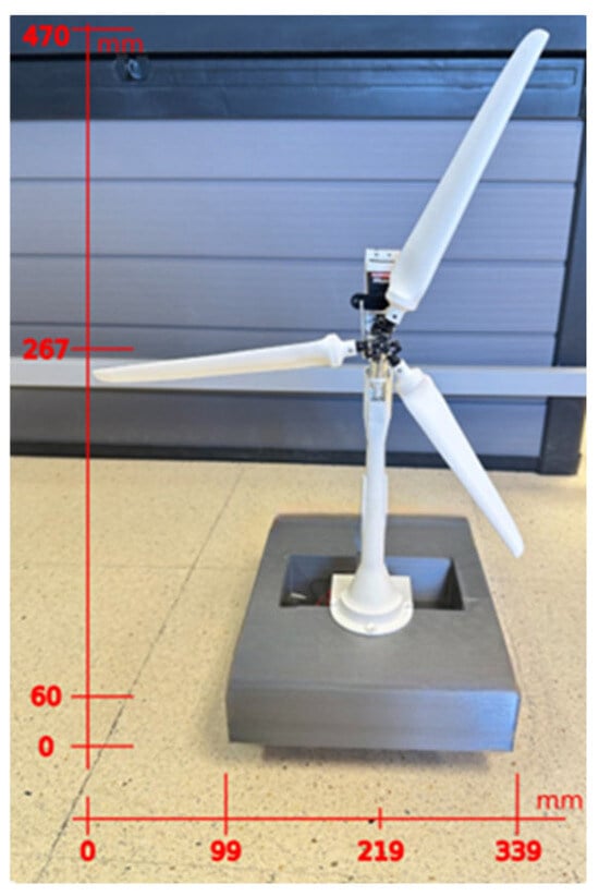
Figure 12.
Photograph of the assembled prototype with reference scale.
In these experiments, the wind speed and blade pitch angle are varied over a range of values. Specifically, three wind speeds and five angular positions are combined:
- Wind speeds = [3.70, 4.50, 5.50] m/s
- Pitch angles: = [0, 5, 10, 15, 20] degrees
The variables measured during the experimental tests include rotor speed and generated voltage, both related to power generation, as well as the tower’s pitch motion, which can serve as an indicator of structural deflection and vibrations.
The generated, measured and filtered voltage from the pilot wind turbine is shown in Figure 13. This variable is considered equivalent to the power produced by the WT prototype for this initial analysis.
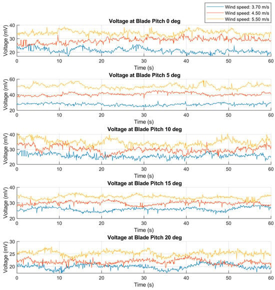
Figure 13.
Generated voltage signals at different wind speeds and blade pitch angles.
The color code in Figure 13 and following corresponds to wind speeds of 3.70 m/s (blue line), 4.50 m/s (red line), and 5.50 m/s (orange line) for pitch angles of 0, 5, 10, 15, and 20 degrees (from top to bottom). The average value of each signal is presented in Table 3, where the maximum energy obtained with the prototype is 51.06 mV, with a wind speed of 5.50 m/s and a pitch angle of 5 degrees, indicating the approximate position of the blade for maximum wind energy capture.

Table 3.
Voltage (mV) and speed (rpm) measured under different wind speeds and pitch angles.
The results in Figure 13 confirm how power generation varies according to wind speed and blade pitch angle, as expected, obtaining reasonable and relatively stable values. As is well known, adjusting the pitch angle is crucial as it modifies the angle of attack of the blades with respect to the incoming wind. This variation directly influences the aerodynamic lift and drag forces acting on the blades and affects the torque produced on the rotor and, thus, the amount of wind energy extracted by the turbine [41].
Similarly, Figure 14 shows the rotor speed for the same wind speed and pitch angle scenarios (the average speeds are presented in Table 3). When pitch angles are set too low, the effective angle of attack is reduced, limiting the lift effect and, therefore, the torque on the rotor. On the other hand, at higher pitch angles, the angle of attack is excessive, increasing the drag force and reducing aerodynamic efficiency.
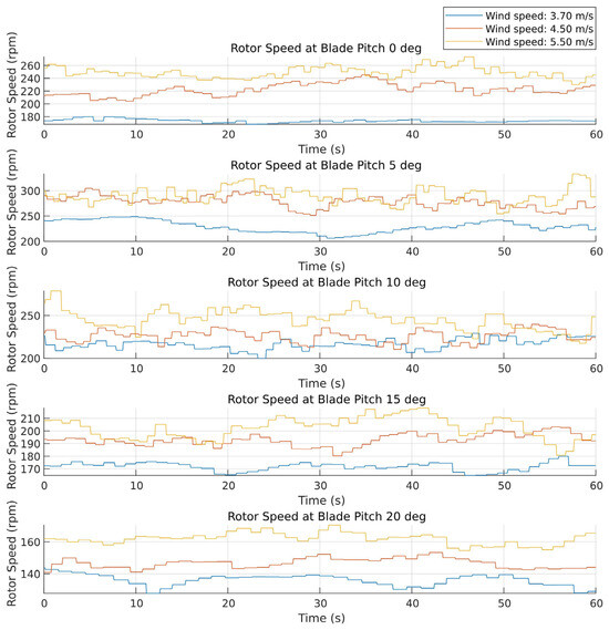
Figure 14.
Rotor speed signals at different wind speeds and blade pitch angles.
While this small-scale prototype is not designed to replicate the full aerodynamic complexity of a commercial wind turbine, the results confirm the expected trend: higher wind speeds, combined with an appropriate pitch angle, generally produce higher rotational speeds and greater energy extraction.
It is important to note that, in a full-scale turbine, the actual power output depends not only on the rotor speed, but also on the torque generated by the blades and the characteristics of the generator and control system. Under the test conditions, the maximum rotor speed for the designed prototype occurred with a blade pitch angle of approximately 5°, which was the best configuration within the limits of the experimental setup, reproducing the general aerodynamic trends reported in the literature for small-scale wind turbines.
On the other hand, it was possible to measure a variable that provides information about the structure’s deflection, specifically the tower’s angular displacement. In each test, data were collected on the tilt angle at the top of the tower. Figure 15 represents this angle (°) under different wind conditions. They are quite similar for all experiments with different blade pitches. The value of this metric has an average amplitude of approximately 0.5°, reaching a maximum of 4° when the rotor operates at maximum speed, a condition in which the system experiences significant dynamic behavior.
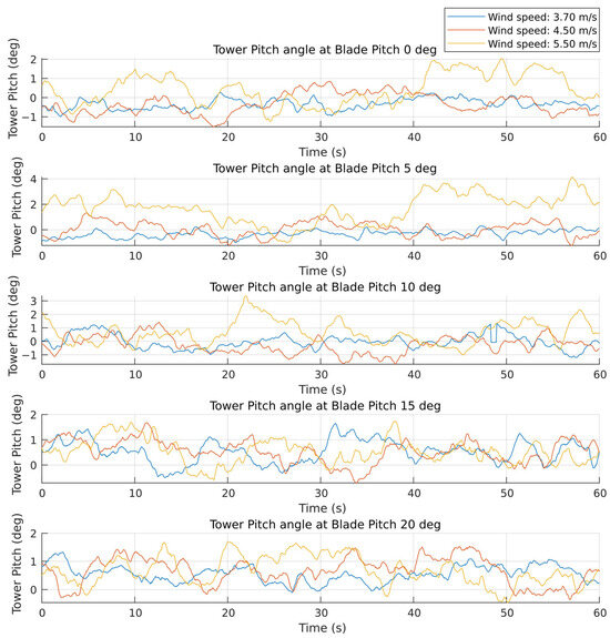
Figure 15.
Tower pitch deflection at different wind speeds and blade pitch angles.
These measurements correspond to the elastic deflection of the PLA tower during tests with the platform fixed and are therefore not related to the platform’s motion. The slight inclination it experiences is due to the prototype’s structural flexibility under the nacelle and rotor loads and shows that the structure is sufficiently stable for aerodynamic testing.
It is important to emphasize that, while the PLA prototype proved to be structurally suitable for testing at this scale, the structural deflection results are not directly scalable to full-size turbines or even larger wind tunnel models because stiffness does not follow linear scaling law. Future work should explore alternative composite materials or manufacturing techniques for studies requiring dynamic structural similarity.
Beyond these structural considerations, evaluating the floating platform is essential for offshore adaptation. As a first approximation of the floating wind turbine configuration, a simple buoyancy test was performed with the platform. For this purpose, the prototype was placed in a water tank.
The mass of the designed platform is 1.250 kg, and the mass of the wind turbine for the tested configuration is 0.260 kg. The density of water, , is 1000 kg/m3. Therefore, according to the buoyancy principle, the weight ( of the system and the buoyancy force ( must be equivalent to ensure buoyancy:
where (Kg) is the mass of the whole device and (m/s2) is the gravity. Using this expression, the volume of water displaced by the system, , can be obtained as follows:
The buoyancy force, , acting on the wind turbine is:
Based on this volume and the geometry of the platform containing the voids, the draft ( of the submerged part of the platform is calculated as follows:
where is the volume of the platform submerged in the water and is the volume of the eight open rectangular cavities.
The experimental results showed that the FOWT was submerged in water approximately 22.47 mm from the surface. This represents less than half the height of the platform, which is sufficient to demonstrate the buoyancy of the prototype design in a wave-free marine environment and provides sufficient headroom to add additional mass to the prototype, such as sensors or complementary components that can be used in more advanced tests.
It can be summarized that the experimentation has demonstrated the ability of the wind turbine scale model to adequately reflect the trends of some variables involved in the device’s operation. These data validate the possible integration of the platform for a FOWT, confirming the expected aerodynamic trends. They also demonstrate that the prototype is functional and meets the initial working requirements for future, more advanced tests, such as full characterization of the model or its implementation as a floating offshore wind turbine in more realistic conditions.
Versatility and Adaptation
Beyond the electrical and structural responses, the experiments confirmed the robustness of the modular design. The wind system allowed for safe assembly and disassembly of its components. Element replacement and reconfiguration were performed quickly, with assembly tests taking less than 5 min for tower and blade swaps. This demonstrates the feasibility of iterative prototyping.
This adaptability is crucial for scaling the prototype to different test facilities and wind turbine configurations. Therefore, this modularity facilitates device customization without the need to redesign the entire system to build a new model.
Furthermore, the printed structure can be easily scaled and modified using CAD software, allowing for deeper analysis of the parts and their behavior, as well as functional adaptation to specific geometric and mechanical requirements and experimental environments. In this way, the prototype provides a flexible research tool that can be adapted to future research on floating offshore wind turbines.
5. Conclusions
This work presents the design and initial validation of a small-scale modular offshore wind turbine prototype, developed using CAD tools and 3D printing. The modular approach proved effective for rapid assembly and reconfiguration, with the ability to replace components in less than five minutes. This highlights its suitability for laboratory testing and differentiates it from more rigid prototyping approaches. Furthermore, the elements for implementing pitch control are integrated, a lack in many wind turbine prototypes of the size proposed here.
The prototype was developed based on the geometric characteristics of a wind system, the coupling of components, and considering the physical characteristics associated with the standard layout of a general-purpose horizontal-axis wind turbine, without applying external loads or advanced control strategies.
Experimental results confirmed that the prototype reproduces the expected aerodynamic tendencies and operational behaviors of a wind device. The WT responded consistently to changes in wind speed and blade pitch angle, with maximum performance observed at a pitch of 5° and a wind speed of 5.5 m/s, reaching 335 RPM and an output of 51.06 mV, the configuration identified as having the maximum capacity of the model. Structural stability was also verified, as tower oscillations remained within a 4° range, consistent with the expected elastic behavior of PLA and validating the robustness of the modular joints. These results demonstrate that, although simplified, the prototype successfully captures the fundamental interactions between aerodynamics and structure in scaled-down wind turbines.
Therefore, the prototype is presented as a flexible experimental tool for analyzing wind turbine energy production and structural responses under controlled wind conditions. However, this study represents an initial stage of development, with successful tests focused on system integration and functional verification.
After confirming the prototype functionality, it is necessary to advance this line of development. Future work will focus on improving the model through detailed mechanical analysis of each component and the assembly to optimize the design. It is also necessary to characterize the prototype and design active control systems for optimal power generation. In this line, the electrical characterization of the wind turbine generator, encompassing voltage, current, and connection parameters, along with the power curve associated with the power coefficient (Cp), wind speed vs. power, and tip speed ratio (TSR) curves, will be determined in the next step. We plan to implement a measurement circuit with a known load to characterize the generator and this way, derive some characteristics such as the power coefficient. Similarly, when applying it to marine turbines, it is necessary to delve deeper into the hydrostatic stability and hydrodynamic responses of the floating platform, adapting the system to marine environments in wave tank experiments.
Author Contributions
Conceptualization, S.E.; Methodology, M.S.; Software, E.M.-P.; Validation, E.M.-P., S.E. and M.S.; Investigation, E.M.-P.; Writing—original draft, E.M.-P.; Writing—review & editing, S.E. and M.S.; Supervision, S.E. and M.S. All authors have read and agreed to the published version of the manuscript.
Funding
This research was partially funded by the Spanish Ministry of Science and Innovation under the project MCI/AEI/FEDER number PID2021-123543OB-C21 and PID2024-155653OB-C21.
Data Availability Statement
The original contributions presented in this study are included in the article. Further inquiries can be directed to the corresponding author.
Conflicts of Interest
The authors declare no conflict of interest.
References
- International Energy Agency—IEA. World Energy Outlook 2023; International Energy Agency: Paris, France, 2023; Available online: https://www.iea.org/reports/world-energy-outlook-2023 (accessed on 5 June 2025).
- Intergovernmental Panel on Climate Change (IPCC). Climate Change 2022: Mitigation of Climate Change. Contribution of Working Group III to the Sixth Assessment Report of the IPCC; Shukla, P.R., Skea, J., Slade, R., Al Khourdajie, A., van Diemen, R., McCollum, D., Pathak, M., Some, S., Vyas, P., Fradera, R., et al., Eds.; Cambridge University Press: Cambridge, UK; New York, NY, USA, 2022. [Google Scholar] [CrossRef]
- Farghali, M.; Osman, A.I.; Chen, Z.; Abdelhaleem, A.; Ihara, I.; Mohamed, I.M.A.; Yap, P.-S.; Rooney, D.W. Social, environmental, and economic consequences of integrating renewable energies in the Electricity Sector: A Review. Environ. Chem. Lett. 2023, 21, 1381–1418. [Google Scholar] [CrossRef]
- REN21. Renewables 2024 Global Status Report. París: REN21 Secretariat. 2024. Available online: https://www.ren21.net/gsr-2024/ (accessed on 5 June 2025).
- IRENA. Renewable Power Generation Costs in 2024; International Renewable Energy Agency: Abu Dhabi, United Arab Emirates, 2025. [Google Scholar]
- Muñoz-Palomeque, E.; Sierra-García, J.E.; Santos, M. Enhancing offshore wind turbines performance with hybrid control strategies using neural networks and conventional controllers. J. Comput. Des. Eng. 2025, 12, 80–97. [Google Scholar] [CrossRef]
- Shafiee, M. Maintenance logistics organization for offshore wind energy: Current progress and future perspectives. Renew. Energy 2015, 77, 182–193. [Google Scholar] [CrossRef]
- Desalegn, B.; Gebeyehu, D.; Tamrat, B.; Tadiwose, T.; Lata, A. Onshore versus offshore wind power trends and recent study practices in modeling of wind turbines’ life-cycle impact assessments. Clean. Eng. Technol. 2023, 17, 100691. [Google Scholar] [CrossRef]
- Ribeiro, J.A.; Ribeiro, B.A.; Pimenta, F.; Tavares, S.M.; Zhang, J.; Ahmed, F. Offshore wind turbine tower design and optimization: A review and AI-Driven Future Directions. Appl. Energy 2025, 397, 126294. [Google Scholar] [CrossRef]
- Bayat, S.; Lee, Y.H.; Allison, J.T. Nested control co-design of a spar buoy horizontal-axis floating offshore wind turbine. Ocean Eng. 2025, 328, 121037. [Google Scholar] [CrossRef]
- Jung, C.; Schindler, D. The properties of the global offshore wind turbine fleet. Renew. Sustain. Energy Rev. 2023, 186, 113667. [Google Scholar] [CrossRef]
- Global Wind Energy Council (GWEC). Global Wind Report 2025; Global Wind Energy Council: Brussels, Belgium, 2025. [Google Scholar]
- Musial, W.; Beiter, P.; Spitsen, P.; Duffy, P.; Shields, M.; Hernando, D.M.; Hammond, R.; Marquis, M.; King, J.; Sathish, S. Offshore Wind Market Report: 2023 Edition; U.S. Department of Energy, National Renewable Energy Laboratory (NREL): Golden, CO, USA, 2023. [Google Scholar]
- Ma, X.; Li, M.; Li, W.; Liu, Y. Overview of offshore wind power technologies. Sustainability 2025, 17, 596. [Google Scholar] [CrossRef]
- Barooni, M.; Ashuri, T.; Sogut, D.V.; Wood, S.; Taleghani, S.G. Floating offshore wind turbines: Current status and future prospects. Energies 2022, 16, 2. [Google Scholar] [CrossRef]
- Boo, S.Y.; Ha, Y.-J.; Shelley, S.A.; Park, J.-Y.; Lim, C.-H.; Kim, K.-H. Concept design of a 15 MW TLP-type floating wind platform for Korean offshore installation. J. Mar. Sci. Eng. 2024, 12, 796. [Google Scholar] [CrossRef]
- Su, X.; Wang, X.; Xu, W.; Yuan, L.; Xiong, C.; Chen, J. Offshore wind power: Progress of the edge tool, which can promote sustainable energy development. Sustainability 2024, 16, 7810. [Google Scholar] [CrossRef]
- Muñoz-Palomeque, E.; Sierra-García, J.E.; Santos, M. Wind turbine maximum power point tracking control based on unsupervised neural networks. J. Comput. Des. Eng. 2023, 10, 108–121. [Google Scholar] [CrossRef]
- Sierra-García, J.E.; Santos, M. Deep learning and fuzzy logic to implement a hybrid wind turbine pitch control. Neural Comput. Appl. 2022, 34, 10503–10517. [Google Scholar] [CrossRef]
- Galán-Lavado, A.; Santos, M. Analysis of the effects of the location of passive control devices on the platform of a floating wind turbine. Energies 2021, 14, 2850. [Google Scholar] [CrossRef]
- Aboutalebi, P.; Garrido, A.J.; Schallenberg-Rodriguez, J.; Garrido, I. Validation of vibration reduction in barge-type floating offshore wind turbines with oscillating water columns through experimental and numerical analyses. Front. Built Environ. 2024, 10, 1497123. [Google Scholar] [CrossRef]
- Pegalajar-Jurado, A.; Bredmose, H.; Borg, M. Multi-level hydrodynamic modelling of a scaled 10MW TLP wind turbine. Energy Procedia 2016, 94, 124–132. [Google Scholar] [CrossRef]
- Du, S.; Zhou, J.; Li, F. Active motion control of platform and rotor coupling system for floating offshore wind turbines. Mech. Syst. Signal Process. 2025, 228, 112484. [Google Scholar] [CrossRef]
- Wang, Y.; Ahmed, A.; Azam, A.; Bing, D.; Shan, Z.; Zhang, Z.; Tariq, M.K.; Sultana, J.; Mushtaq, R.T.; Mehboob, A.; et al. Applications of Additive Manufacturing (AM) in sustainable energy generation and battle against COVID-19 pandemic: The knowledge evolution of 3d printing. J. Manuf. Syst. 2021, 60, 709–733. [Google Scholar] [CrossRef]
- Lerche, J.; Enevoldsen, P.; Seppänen, O. Application of takt and Kanban to modular wind turbine construction. J. Constr. Eng. Manag. 2022, 148, 05021015. [Google Scholar] [CrossRef]
- Bianchini, A.; Bangga, G.; Baring-Gould, I.; Croce, A.; Cruz, J.I.; Damiani, R.; Erfort, G.; Ferreira, C.S.; Infield, D.; Nayeri, C.N.; et al. Current status and grand challenges for small wind turbine technology. Wind. Energy Sci. 2022, 7, 2003–2037. [Google Scholar] [CrossRef]
- Calautit, K.; Johnstone, C. State-of-the-art review of micro to small-scale wind energy harvesting technologies for building integration. Energy Convers. Manag. X 2023, 20, 100457. [Google Scholar] [CrossRef]
- O'Neill, F.; Mehmanparast, A. A review of additive manufacturing capabilities for potential application in offshore renewable energy structures. Forces Mech. 2024, 14, 100255. [Google Scholar] [CrossRef]
- Wulandana, R.; Werner, G.; Gardner, B. Integrated Wind Turbine Blade Design Education: Combining theory, simulation, CAD, and experimental testing. In Proceedings of the ASEE Annual Conference & Exposition, Montreal, QC, Canada, 22–25 June 2025. [Google Scholar] [CrossRef]
- Leong, W.Y. 3D printing for Renewable Energy Technologies. ASM Sci. J. 2025, 20, 1–10. [Google Scholar] [CrossRef]
- Nagai, B.M.; Ameku, K.; Roy, J.N. Performance of a 3 kW wind turbine generator with Variable Pitch Control System. Appl. Energy 2009, 86, 1774–1782. [Google Scholar] [CrossRef]
- Mohammadi, E.; Fadaeinedjad, R.; Naji, H.R. Platform for design, simulation, and experimental evaluation of small wind turbines. IET Renew. Power Gener. 2019, 13, 1576–1586. [Google Scholar] [CrossRef]
- Hamza, G.; Hammadi, M.; Barkallah, M.; Choley, J.-Y.; Riviere, A.; Louati, J.; Haddar, M. Conceptual design methodology for the preliminary study of a mechatronic system: Application to wind turbine system. Mech. Ind. 2017, 18, 413. [Google Scholar] [CrossRef]
- Verma, N.; Baloni, B.D. Influence of Reynolds number consideration for aerodynamic characteristics of airfoil on the blade design of small horizontal axis wind turbine. Int. J. Green Energy 2021, 19, 733–746. [Google Scholar] [CrossRef]
- Chen, J.; Kim, M.-H. Review of recent offshore wind turbine research and optimization methodologies in their design. J. Mar. Sci. Eng. 2021, 10, 28. [Google Scholar] [CrossRef]
- Li, Y.; Molazem, A.; Kuo, H.-I.; Ahmadi, V.; Shastri, V.P. Comparative analysis of Dimensional Accuracy in PLA-based 3D printing: Effects of key printing parameters and related variables. Polymers 2025, 17, 1698. [Google Scholar] [CrossRef]
- Mahmoud, M.; Semeraro, C.; Abdelkareem, M.A.; Olabi, A.G. Designing and prototyping the architecture of a digital twin for wind turbine. Int. J. Thermofluids 2024, 22, 100622. [Google Scholar] [CrossRef]
- Kumar, V.; Pavan, M. Modal Analysis of NACA 4412 Airfoil Based Air-Wing Using Different Composite Materials. Int. J. Eng. Sci. Adv. Technol. 2018, 18, 26–35. [Google Scholar]
- Sakthi, S.; Muthukumaran, G.; Balasubramaniyan, S. Windmill Power Generation Using Mult-Generator and Single Rotor (Horizontal and Vertical Blade). J. Energy Technol. Policy 2012, 2, 11–20. [Google Scholar]
- Xu, H.; Jia, K.; Wang, E.; Xiao, Q.; Incecik, A. Effects of moonpools and heave plates on hydrodynamic performance of a barge-type floating offshore wind turbine platform in regular waves. Phys. Fluids 2025, 37, 087166. [Google Scholar] [CrossRef]
- Firoozi, A.A.; Hejazi, F.; Firoozi, A.A. Advancing Wind Energy Efficiency: A systematic review of aerodynamic optimization in wind turbine blade design. Energies 2024, 17, 2919. [Google Scholar] [CrossRef]
Disclaimer/Publisher’s Note: The statements, opinions and data contained in all publications are solely those of the individual author(s) and contributor(s) and not of MDPI and/or the editor(s). MDPI and/or the editor(s) disclaim responsibility for any injury to people or property resulting from any ideas, methods, instructions or products referred to in the content. |
© 2025 by the authors. Licensee MDPI, Basel, Switzerland. This article is an open access article distributed under the terms and conditions of the Creative Commons Attribution (CC BY) license (https://creativecommons.org/licenses/by/4.0/).