Article

Research on Fractional-Order Sliding Mode Control of Fractional-Order Permanent Magnet Direct-Drive Wind Power System

College of Electrical Engineering, Guangxi University, Nanning 530004, China
*
Author to whom correspondence should be addressed.
Machines 2025, 13(10), 928; https://doi.org/10.3390/machines13100928
Submission received: 14 September 2025 / Revised: 3 October 2025 / Accepted: 7 October 2025 / Published: 8 October 2025
(This article belongs to the Section Electromechanical Energy Conversion Systems)

Abstract

A large number of practical systems show pronounced fractional-order features. In comparison with integer-order calculus, fractional-order calculus has been demonstrated to possess enhanced precision in the description of the dynamic behavior of complex systems. The increase in control accuracy and flexibility results from this improvement. This study explores a direct-drive wind power generation system featuring permanent magnets, which incorporates fractional-order direct current bus (DC-bus) capacitor and fractional-order inductor–capacitor–inductor (FOLCL) grid-connected filter. For the machine-side rectifier, a fractional-order sliding mode (FOSM) speed outer-loop control and a fractional-order proportional–integral (FOPI) current inner-loop control were designed. A voltage outer-loop control using FOSM and a current inner-loop control using FOPI were developed for the grid-side inverter. Through simulation analyses under various wind speeds and grid fault conditions, it is demonstrated that compared to a control strategy using FOPI controllers in both inner and outer loops, the proposed control scheme which employs a FOSM outer-loop and reduces the overshoot of DC-bus voltage and grid-connected current by 21.51% and 32.49%, respectively, under sudden wind speed changes. Furthermore, during grid voltage sag faults, the maximum drop in DC-bus voltage and grid-connected active power are reduced by 65.38% and 33.38%, respectively. These results highlight the proposed method’s superior dynamic and static performance, as well as enhanced resistance to disturbances.

1. Introduction

As the global economy develops rapidly, all countries have taken the development and utilization of clean energy as a key goal for sustainable development. As a type of environmentally friendly renewable energy, wind energy is playing an increasingly critical role in shaping the global energy structure [1]. Permanent magnet direct-drive wind power systems have been extensively utilized in the wind energy sector due to their straightforward design, elevated operational efficiency, and minimal maintenance requirements [2,3].
Conventional research on permanent magnet direct-drive wind power systems has predominantly relied on integer-order calculus for modeling and control. However, research has demonstrated that actual controlled plants and basic components, such as capacitors and inductors, are inherently fractional-order. The application of fractional calculus has been demonstrated to enable more accurate modeling and improve control performance [4,5,6,7]. In recent years, scholars have conducted research on fractional-order modeling and fractional-order control for permanent magnet direct-drive wind power systems, yielding notable results. In permanent magnet direct-drive wind power systems, machine-side and grid-side converters, together with grid connection filters, are core components for energy conversion and grid connection. Their dynamic qualities directly affect the system’s stability and efficiency. As reported in Reference [8], a fractional-order model was established for the single-phase pulse–width modulation (PWM) rectifier. The analysis based on the instantaneous reactive power theory and load variation tests was conducted to compare the integer-order and fractional-order models from two aspects. It was verified that the single-phase PWM rectifier fractional-order model is more in line with the real system. Reference [9] presents a fractional-order mathematical model of the three-phase grid-connected inverter, taking into account both high-frequency and low-frequency characteristics for photovoltaic grid-connected systems. The simulation results have shown that, in comparison to integer-order models, fractional-order photovoltaic three-phase inverters have better dynamic and static properties. For filters in grid-connected systems, Reference [10] integrated fractional-order inductor–capacitor–inductor (FOLCL) filters into the grid-side inverters of wind power systems and combined them with fractional-order proportional–integral (FOPI) control strategies to optimize the orders of fractional-order capacitors and inductors. This integration significantly suppressed the resonance of LCL filters. Furthermore, the study confirmed that fractional-order grid-connected inverter systems have greater advantages over integer-order systems in terms of grid-connected power factor and direct current bus (DC-bus) voltage stability. As demonstrated in the aforementioned literature, fractional-order models can more accurately describe the actual operational mechanisms of complex systems. It can be concluded that, for permanent magnet direct-drive wind power systems characterized by strong nonlinearity and multivariable coupling, the adoption of machine-side fractional-order converters, grid-side fractional-order converters, and fractional-order filters can more accurately reveal the systems’ complex operating mechanisms.
It follows that, for permanent magnet direct-drive wind power systems with strong nonlinearity and multivariable coupling, the adoption of machine-side fractional-order converters, grid-side fractional-order converters, and fractional-order filters can more accurately characterize their complex operating mechanisms. Additionally, these systems are susceptible to external disturbances during operation, such as wind speed fluctuations and grid disturbances [11,12,13]. As a result, as the main control object of this system, the control of the machine-side and grid-side converters mainly focuses on the main part of this control. In recent years, the majority of studies have utilized conventional PI control [14], but its precision and disturbance rejection capabilities are still inadequate. Against this backdrop, the development of fractional calculus theory has provided new insights for the control of such complex systems. Common fractional-order control methods include fractional-order proportional–integral–derivative control (FOPID) [15,16,17], fractional-order sliding mode control (FOSMC) [18,19], fractional-order adaptive control [20], and fractional-order active disturbance rejection control (FOADRC) [21].
Reference [22] introduces a new FOPID controller to the control of permanent magnet direct-drive synchronous motors, which replaces the conventional PI regulator designed in accordance with traditional engineering principles, and thereby enhances the motor’s speed regulation performance. Reference [23] proposes a combined method integrating an intelligent PI control algorithm and a sliding mode control algorithm. Although this method enhances the transient response and system robustness of permanent magnet synchronous motors (PMSM), it fails to address the chattering problem inherent in sliding mode control.
To solve this issue, some scholars have incorporated fractional calculus operators into the method [24,25], confirming that FOSMC can reduce chattering to a certain extent and improve control performance. Reference [26] proposes integer-order PI controllers, fractional-order PI controllers, and fuzzy fractional-order controllers are designed to achieve Maximum Power Point Tracking (MPPT) control for permanent magnet synchronous wind power systems. The results show that whether under step wind speed or random wind speed, the fuzzy fractional-order controller exhibits more excellent MPPT performance and stronger robustness compared with the other two controllers. The above studies fully demonstrate that the adoption of fractional-order control can optimize the dynamic performance and anti-disturbance capability of systems under complex operating conditions.
As of right now, there are no published studies that examine the use of FOSMC and fractional calculus modeling in permanent magnet direct-drive wind power systems. Therefore, this study focuses on the fractional-order permanent magnet direct-drive wind power generation system that incorporates a DC-bus fractional-order capacitor and a FOLCL filter, and proceeds to design a corresponding FOSMC strategy. The subsequent chapters are arranged as follows: Section 1 introduces the fractional-order permanent magnet direct-drive wind power system model. Section 2 presents the design of the fractional-order control strategy. Section 3 conducts simulation analysis of the system. Section 4 draws conclusions.

2. Fractional-Order Permanent Magnet Direct-Drive Wind Power System Model

The main circuit of the fractional-order permanent magnet direct-drive wind power generation system investigated in this study is illustrated in Figure 1 [10]. The system is composed primarily of wind turbines, permanent magnet synchronous generators, fractional-order back-to-back converters (incorporating fractional-order DC-bus capacitors), FOLCL grid-connected filters, and other components. The key difference between fractional-order and traditional permanent magnet direct-drive wind power systems lies in the use of fractional-order elements in both the DC-bus capacitor and the inductors and capacitors of the LCL filter. As illustrated in Figure 1, v is the wind speed, isa, isb, and isc represent stator currents. iin denotes the output current of the machine-side rectifier. i represents the input current of the grid-side inverter. ega, egb, and egc are defined as the voltages in a three-phase grid. The input currents of the FOLCL filter are denoted as iga1, igb1, and igc1. iga2, igb2, and igc2 are represented as the output currents of the FOLCL filter. udc is represented as the DC-bus voltage. The fractional-order DC-bus capacitor and the capacitor in the FOLCL filter are represented by the symbols Cdc and C, respectively. α and β denote the orders of the fractional inductor and fractional capacitor, respectively, where α, β ∈ (0, 2). The filter inductors and resistors on the inverter-side and grid-side are labeled as L1, L2, R1, and R2, respectively. Wind turbines convert wind energy into mechanical energy, which is subsequently converted into electrical energy by permanent magnet direct-drive synchronous generators. Finally, the electrical energy is processed through fractional-order back-to-back converters and filters before being fed into the power grid.

2.1. Wind Turbine Model

The mechanical power output (Pm) of the wind turbine is described by [27]:
P m = 1 2 ρ π r 2 v 3 C P λ , θ
In this equation, ρ denotes the air density, r specifies the rotor radius, and Cp signifies the power coefficient, which is a function of the pitch angle θ and the tip–speed ratio λ.
In wind turbine control, when the wind speed exceeds the cut-in wind speed but below the rated wind speed, maximum power point tracking is achieved by setting the pitch angle θ = 0 and managing the tip–speed ratio λ. For wind speeds that fall between the rated value and the cut-out threshold, regulation of the pitch angle θ ensures that the active power output remains stabilized at its rated level.

2.2. Permanent Magnet Direct-Drive Synchronous Generator Model

In the dq coordinate system, the stator voltage equation of a permanent magnet direct-drive synchronous generator is [28,29]:
u sd = R s i sd ω e L sq i sq + L sd D t 1 i sd u sq = R s i sq + ω e L sd i sd + ω e ψ f + L sq D t 1 i sq
In the equation, usd and usq represent the dq-axis components of the stator voltage, while isd and isq are the dq-axis components of the stator current. Lsd and Lsq represent the dq-axis components of the stator inductance, while Rs refers to the armature resistance of the generator. The electrical angular velocity of the generator is denoted as ωe, while the mechanical angular velocity is represented by ω, These are related by the equation ωe = = 2πpn, where p is the number of pole pairs and n is the rotational speed. Additionally, ψf refers to the flux linkage of the permanent magnet, and D t 1 represents the first-order differential operator from time 0 to time t.
The electromagnetic torque equation is expressed as follows:
T e = 3 2 p ψ f i sq + L sd L sq i sd i sq
For the generator, the following is the equation of motion:
T e T L = J D t 1 ω + F ω
In the equation, Te and TL represent the electromagnetic torque and load torque, respectively. F represents the friction coefficient, and J stands for the rotational inertia.

2.3. Fractional-Order Back-to-Back Converter Model

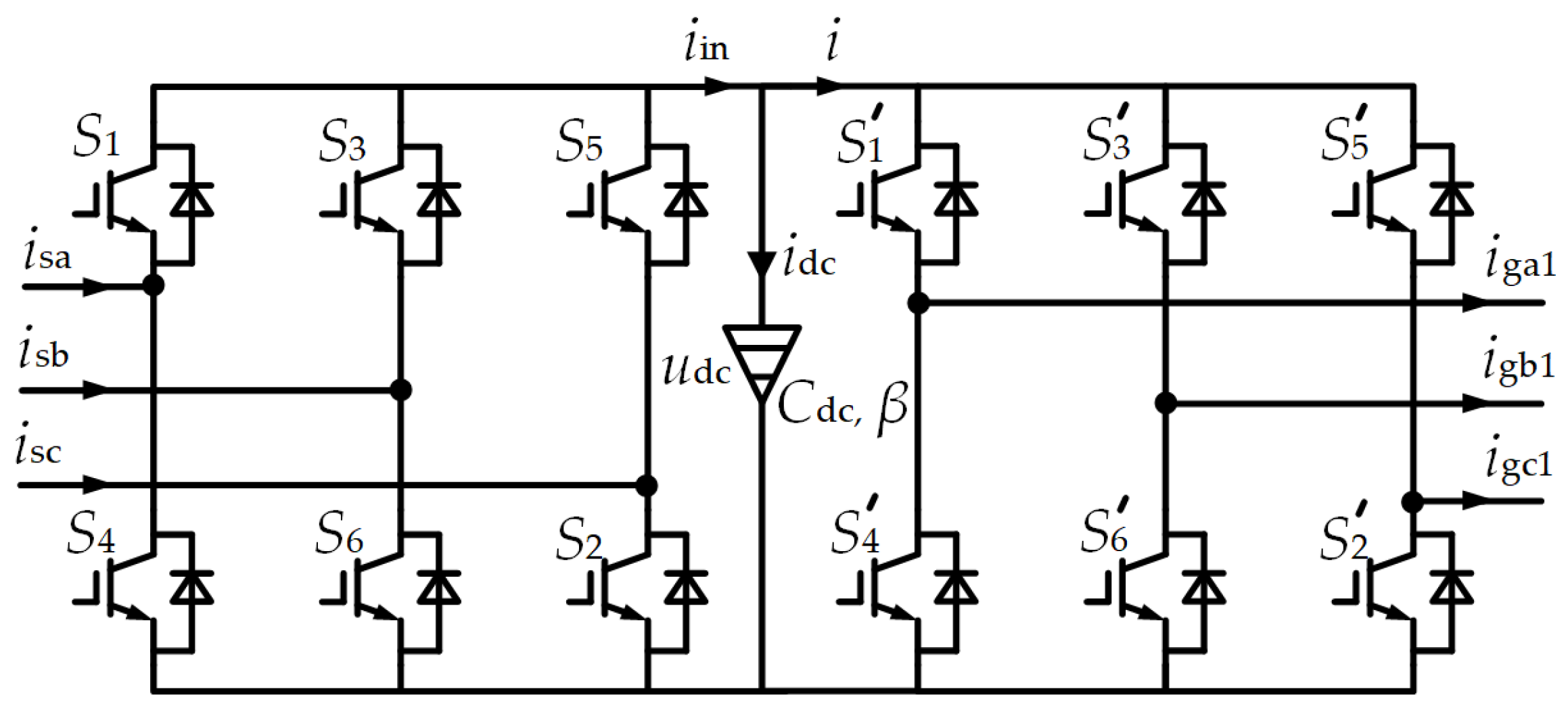
In the fractional-order permanent magnet direct-drive wind power system, the fractional-order back-to-back converter is a core component, as illustrated in Figure 2. The DC-bus capacitor exhibits fractional-order characteristics. S1S6 and S1′–S6′ act as switching devices.
The electrical equation of the fractional-order DC-bus capacitor is as follows:
i dc = C D t β u dc
In this equation, D t β denotes the β-order differential operator from time 0 to t.

2.4. Fractional-Order Grid-Connected Filter Model

In new energy grid-connected systems, the optimized design of filter topologies is crucial for suppressing resonance and improving power quality. Compared with conventional LCL filters, FOLCL filters exhibit greater flexibility in structural design and can effectively suppress resonance phenomena from the source [10]. The FOLCL filter topology is illustrated in Figure 3.
According to Kirchhoff’s voltage and current laws, the state equations of the grid-side converter in the three-phase stationary coordinate system can be derived as follows:
L 1 D t α i gk 1 = R 1 i gk 1 u ck + u gk L 2 D t α i gk 2 = R 2 i gk 2 + u ck e gk C D t β i u ck = i gk 1 i gk 2
In the aforementioned equation, k is equivalent to a, b, c, and uck represent the capacitor voltages of the FOLCL filter, while ugk denotes the inverter output voltage.
To make control design and analysis easier, Equation (6) is transformed from the three-phase stationary coordinate system to the two-phase rotating coordinate system [30]. Subsequently, the dynamic equation of inductor L1 in the dq coordinate system is deduced as follows:
L 1 D t α i gd 1 = L 1 A R 1 i gd 1 + L 1 B i gq 1 + u gd u cd L 1 D t α i gq 1 = L 1 B i gd 1 + L 1 A R 1 i gq 1 + u gq u cq
Here, A = ω α cos α π 2 , B = ω α sin α π 2 .
The following is the dynamic equation of inductor L2 on the dq-axis.
L 2 D t α i gd 2 = L 2 A R 2 i gd 2 + L 2 B i gq 2 e gd + u cd L 2 D t α i gq 2 = L 2 B i gd 2 + L 2 A R 2 i gq 2 e gq + u cq
The dynamic equation of filter capacitor C on the dq-axis is as follows:
C D t β u cd = C A u cd + C B u cq + i gd 1 i gd 2 C D t β u cq = C B u cd + C A u cq + i gq 1 i gq 2
As can be seen from Equations (7) through (9), there is a cross-coupling effect between the d and q electrical quantities of the FOLCL filter.

3. Fractional-Order Control Design

3.1. Machine-Side Rectifier Fractional-Order Control

3.1.1. FOPI Current Inner-Loop Control with dq-Axis Decoupling

The goal of the machine-side converter’s control is to manage the generator’s electromagnetic torque to control its speed, allowing the wind turbine to function close to the optimal tip speed ratio. To improve the generator’s efficiency and performance, the most commonly used control strategy is rotor field-oriented vector control with isd = 0, which simplifies Equation (3) to:
T e = 3 2 p ψ f i sq
It can be demonstrated from the equation that the control of electromagnetic torque Te can be achieved by regulating the current component isq. Since the stator current components isd and isq in Equation (2) are mutually coupled via mutual inductance, feedforward control is introduced to achieve decoupling. To improve control performance, a current inner-loop FOPI controller is designed in this paper, with the corresponding control equation provided as follows:
u sd = R s i sd ω e L sq i sq + k p i sd i sd + k i s η i sd i sd u sq = R s i sq + ω e L sd i sd + ω e ψ f + k p i sq i sq + k i s η i sq i sq
In the formula, η denotes the fractional integration order, while kp and ki represent the proportional and integral coefficients, respectively.

3.1.2. FOSM Speed Outer-Loop Control

Reference [22] demonstrates that FOPI control in the speed outer-loop exhibits excellent speed regulation performance, with substantially improved dynamic performance and robustness compared to conventional PI control. However, in complex operating scenarios, the system requires enhanced anti-interference capability. To this end, this paper introduces FOSMC in the speed outer-loop design, by designing FOSM surfaces and FOSM reaching laws. This design optimizes the system’s dynamic response and suppresses chattering by leveraging the fractional-order characteristics. By adopting rotor field-oriented vector control with isd = 0 and ignoring the damping coefficient, the mathematical model of the permanent magnet direct-drive synchronous generator in the dq-axis coordinate system can be simplified to:
L sq D t 1 i sq = R s i sq p n ψ f + u sq J D t 1 n = 3 2 p ψ f i sq T L
Based on the mathematical model presented earlier in this paper, the following variables are chosen as the system state variables of the permanent magnet synchronous generator.
x 1 = n n x 2 = D t 1 x 1 = D t 1 n = 3 2 J p ψ f D t 1 i sq + 1 J T L
In the aforementioned equation, x1 and x2 represent the system state variables, while μ denotes the fractional derivative.
Subsequently, differentiating with respect to x2 yields:
D t 1 x 2 = D t 2 n = 3 2 J p ψ f D t 2 i sq
Let H 1 = 3 p ψ f 2 J . Then, the system’s state-space equation can be expressed as:
D t 1 x 1 x 2 = 0 1 0 0 x 1 x 2 D t 2 0 H 1 i sq
The fractional-order sliding-mode surface is designed as follows:
f 1 = c 1 x 1 + D t μ x 1
In the formula, c1 is a constant.
The power rate reaching law offers rapid convergence for systems distant from the sliding mode surface, while allowing parameter-based chattering reduction during approach. To further enhance these performance metrics, this paper develops a fractional-order fast power rate reaching law to improve both convergence speed and control performance, as shown in Equation (17):
D t μ f 1 = k 0 f 1 σ D t μ sgn f 1 k 1 f 1
In the equation, sgn(f1) denotes the sign function, while k0 and k1 represent constants greater than 0. These constants ensure that f1 and D t μ f 1 have opposite signs, thereby satisfying the stability conditions. This proves the stability of the system under fractional-order fast power-rate reaching law-based sliding mode control [31]. A fractional-order coefficient σ is introduced into the fractional-order power-rate model. The system’s switching speed can be modulated by adjusting the coefficients σ, k0, and k1.
Upon differentiating Equation (16) and combining it with Equation (17), the FOSMC law for the speed outer-loop is obtained as follows:
i sq = 1 H 1 D t 1 μ c 1 x 1 + D t μ ( k 0 f 1 σ D t μ sgn ( f 1 ) + k 1 f 1 )
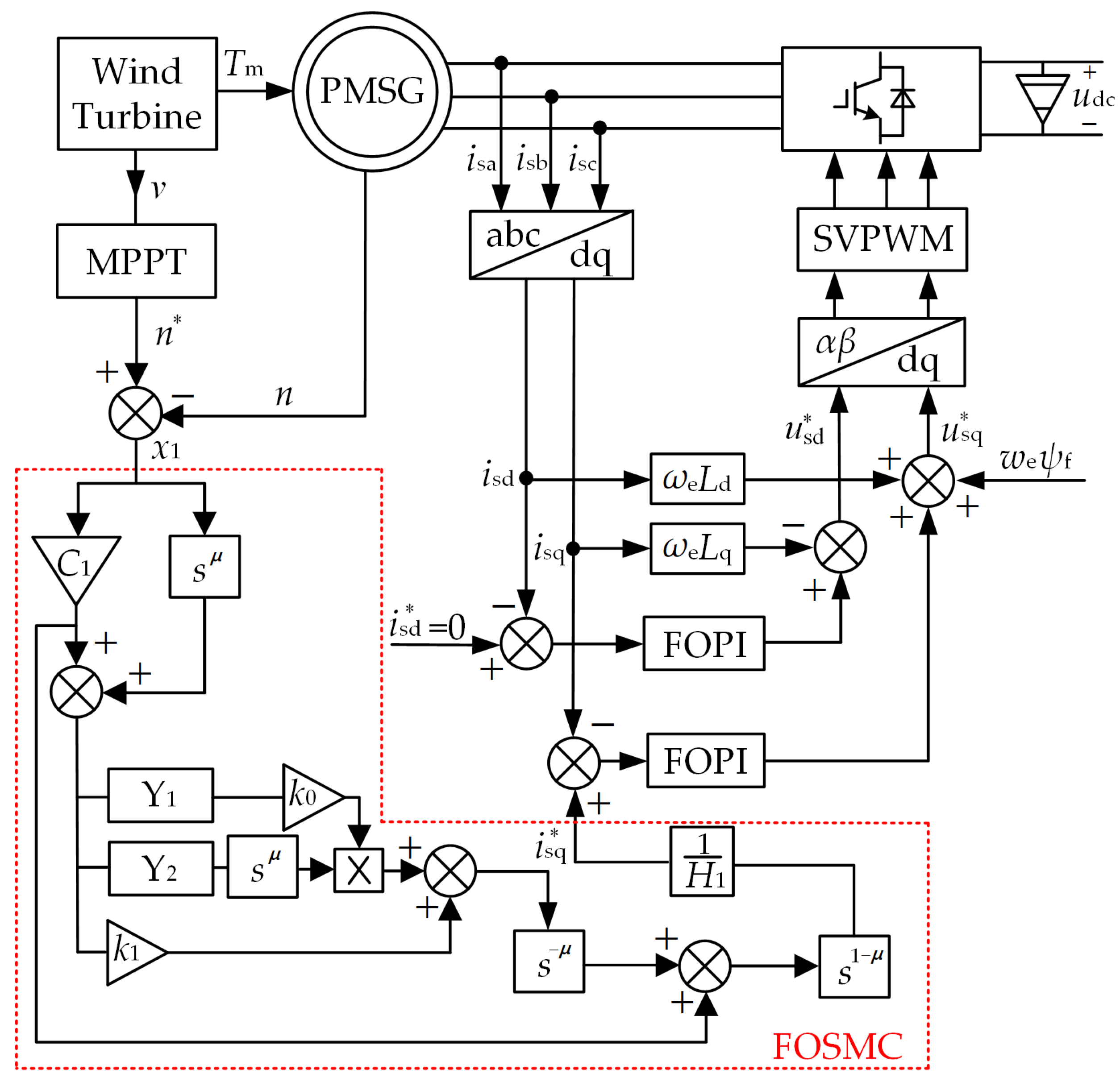
The aforementioned design enables the establishment of a double closed-loop control structure for the machine-side rectifier, incorporating a “FOSM speed outer-loop + dq-axis decoupled FOPI current inner-loop,” as depicted in Figure 4.
As illustrated in the figure, Y1 and Y2 represent the expressions of |f1|σ and sgn(f1), respectively, in the complex frequency domain.

3.2. Grid-Side Inverter Fractional-Order Control

3.2.1. FOPI Current Inner-Loop Control with dq-Axis Decoupling

Given that grid-side converters generally involve the low-frequency dynamics of the power grid when controlling active and reactive power, and that capacitive reactance is significant at low frequencies, the capacitance C in the FOLCL filter can be neglected in control design. By equating the sum of L1 and L2 to a total fractional-order inductance L, the FOLCL filter can be simplified to a fractional-order inductor (FOL) filter. Equations (7) to (9) can thus be simplified as follows:
L D t α i gd = L A R i gd + L B i gq + u gd e gd L D t α i gq = L B i gd + L A R i gq + u gq e gq
where L = L1 + L2 and R = R1 + R2.
The expression of Equation (19) in the complex frequency domain is as follows:
L s α + R L A I gd s = L B I gq s + U gd s E gd s L s α + R L A I gq s = L B I gd s + U gq s E gq s
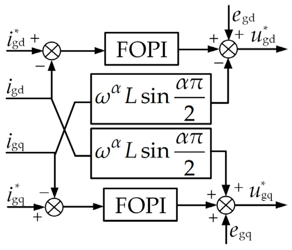
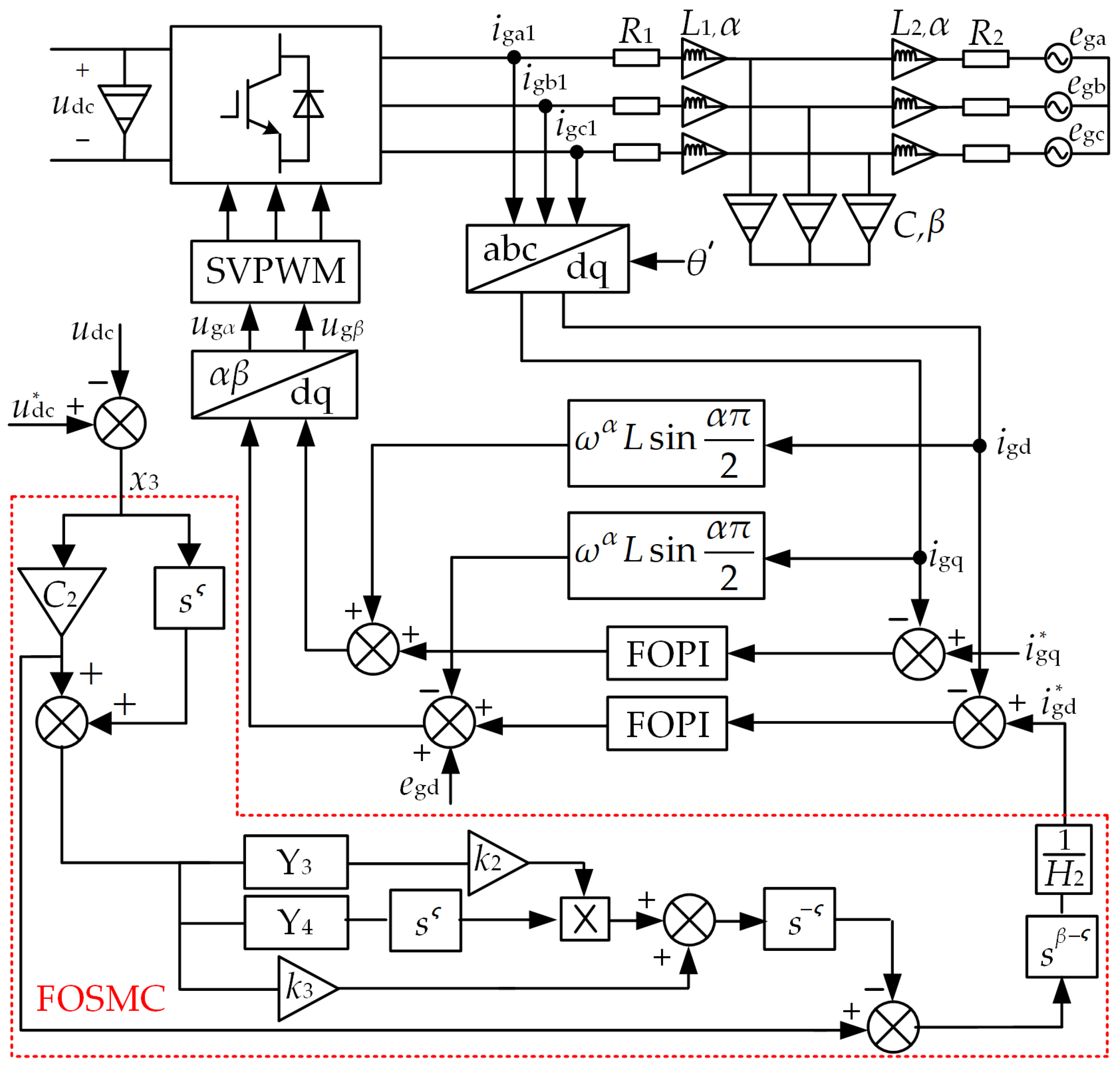
In the equation, Igd, Igq, Ugd, Ugq, Egd, and Egq are the expressions of igd, igq, ugd, ugq, egd, and egq, respectively, in the complex frequency domain. Given the cross-coupling between d-axis and q-axis currents in the rotating coordinate system, a FOPI current inner-loop control is proposed herein for dq-axis decoupling of the grid-side inverter. Based on Equation (19), the control scheme is designed as Equation (21), and its control block diagram is presented in Figure 5.
u gd = e gd ω α L sin α π 2 i gq + k p 0 i gd i gd + k i 0 s η 0 i gd i gd u gq = e gd + ω α L sin α π 2 i gq + k p 0 i gq i gq + k i 0 s η 0 i gq i gq
Through the above design, the decoupled d-axis current control diagram is shown in Figure 6.
As shown in the figure, KPWM is the proportional gain, which characterizes the grid-side inverter’s amplification characteristics under sufficiently high switching frequencies. The proportional and integral coefficients in FOPI are marked as kp0 and ki0, while T0 and Ts correspond to the time constants of the signal filtering delay link and modulation delay link, respectively.

3.2.2. Fractional-Order Sliding-Mode Voltage Outer-Loop Control

The operation principle of the voltage outer-loop is to send an error signal, derived from the discrepancy between the DC-bus voltage udc and its reference voltage, to the controller. This generates a reference current igd, which is then used as the input for the current inner loop. With the aim of enhancing control performance, this study proposes a fractional-order sliding-mode control strategy, and on this basis, develops a fractional-order sliding-mode voltage outer-loop control strategy specifically for the grid-side inverter.
In a three-phase inverter system, the active and reactive power of the system can be explicitly defined on the basis of power calculation equations:
P = 3 2 e gd i gd + e gq i gq Q = 3 2 e gd i gq e gq i gd
In the equation, P and Q denote the active power and reactive power output from the grid-side inverter to the grid, respectively.
To simplify the control, the grid voltage directional vector is utilized, i.e., set egq = 0. Based on Equation (22), the power balance equation is derivable as follows:
i in i dc u dc = 3 2 e gd i gd C D t β u dc = i in 3 2 e gd i gd u dc
Based on the mathematical model of the grid-side inverter, the system’s state variables are chosen as follows:
x 3 = u dc u dc x 4 = D t β x 3 = D t β u dc = 3 e gd 2 C u dc i gd 1 C i in
In this equation, x3 and x4 denote the system’s state variables.
Differentiating x4 with respect to time, we obtain the following equation:
D t β x 4 = D t 2 β x 3 = D t 2 β u dc = 3 e gd 2 C u dc D t β i gd
Define H 2 = 3 e gd 2 C u dc , then:
D t β x 3 x 4 = 0 1 0 0 x 3 x 4 + D t β 0 H 2 i gd
The design for the fractional-order sliding-mode surface is given as follows:
f 2 = c 2 x 3 + D t ς x 3
By differentiating Equation (27), the resulting equation is as follows:
D t ς f 2 = c 2 D t ς x 3 + D t 2 ς x 3
The chosen fractional-order rapid power reaching law is given below:
D t ς f 2 = k 2 f 2 τ D t ς sgn f 2 k 3 f 2
In the formula, ς denotes the fractional differentiation order, while τ represents the fractional-order exponent.
The FOSM voltage outer-loop control law is derived by combining Equations (28) and (29) as follows:
i gd = 1 H 2 D t β ς c 2 x 3 D t ς ( k 2 f 2 τ D t ς sgn ( f 2 ) + k 3 f 2 )
In the equation, sgn(f2) represents the sign function, and k2, k3 are positive constants. These constants guarantee that f2 and D t ς f 2 have opposite signs, thereby satisfying the stability conditions and proving the system stability under fractional-order fast power-law sliding mode control.
According to the design outlined above, the grid-side converter adopts a double closed-loop control structure of “FOSM voltage outer-loop + dq-axis decoupled FOPI current inner-loop,” as shown in Figure 7.
As illustrated in the figure, Y3 and Y4 respectively represent the expressions of |f2|τ and sgn(f2), in the complex frequency domain.

4. Simulation Analysis

Following the above design, a digital simulation model for the fractional-order permanent magnet direct-drive wind power system was established in Matlab/Simulink, with the relevant system parameters presented in Table 1. The parameters of capacitance and inductance are adopted directly from reference [10], where α = 0.85 and β = 0.95. The fractional-order values (α, β) are within (0, 2). According to the fractional-order element theory, they cover the phase range of (−π, π), and α and β make the element characteristics gradually change from positive resistance to integer-order and then to negative resistance. The current satisfies dynamic continuity, power conservation, and the total harmonic distortion (THD) of the power grid is ≤5%. The speed is constrained by the range of tip speed ratio, the overspeed upper limit (the rated wind speed is set to 12 m/s, and the cut-out wind speed is 25 m/s), and the electromechanical balance. The voltage meets the steady-state deviation of ±5%, and the frequency meets the deviation ≤±0.2 Hz. The sampling period is 20 μs, and the toolbox is implemented based on the Caputo definition. The fractional-order sliding mode reaching law enhances robustness with fractional-order differential terms, and chattering suppression is achieved by adjusting the fractional order.
Next, simulations are carried out under varying wind speeds and asymmetric grid faults to compare the “FOSM outer-loop + FOPI inner-loop” control proposed in this paper with the “FOPI outer-loop + FOPI inner-loop” control proposed in [10], so as to verify the effectiveness of the fractional-order sliding-mode outer-loop control.

4.1. Control Parameter Design

The particle swarm optimization (PSO) method is employed in this paper for parameter tuning of the fractional-order controller. Similarly to other evolutionary algorithms, PSO is built around “swarm” and “evolution” concepts, relying on particle fitness values for operation. Particle velocity and position adjustments are shaped by both individual and collective experiences, with the objective of finding the optimal solution across the entire search domain [32]. The optimization process is depicted in Figure 8.
The velocity and position of particles in the search space are determined via the following formula [33]:
j t + 1 = m j t + l 1 o 1 ( P t h t ) + l 2 o 2 ( G t h t ) h t + 1 = h t + j t + 1
Within the equation, h denotes the particle position, j denotes the particle velocity, and m serves as the inertia factor. Acceleration constants are represented by l1 and l2, while o1 and o2 are random numbers in [0, 1]. Pt refers to the particle’s own historical optimal position, and Gₜ signifies the historical global optimal position of the entire particle swarm.
The fitness function is selected as follows:
Z = D t 1 t · e
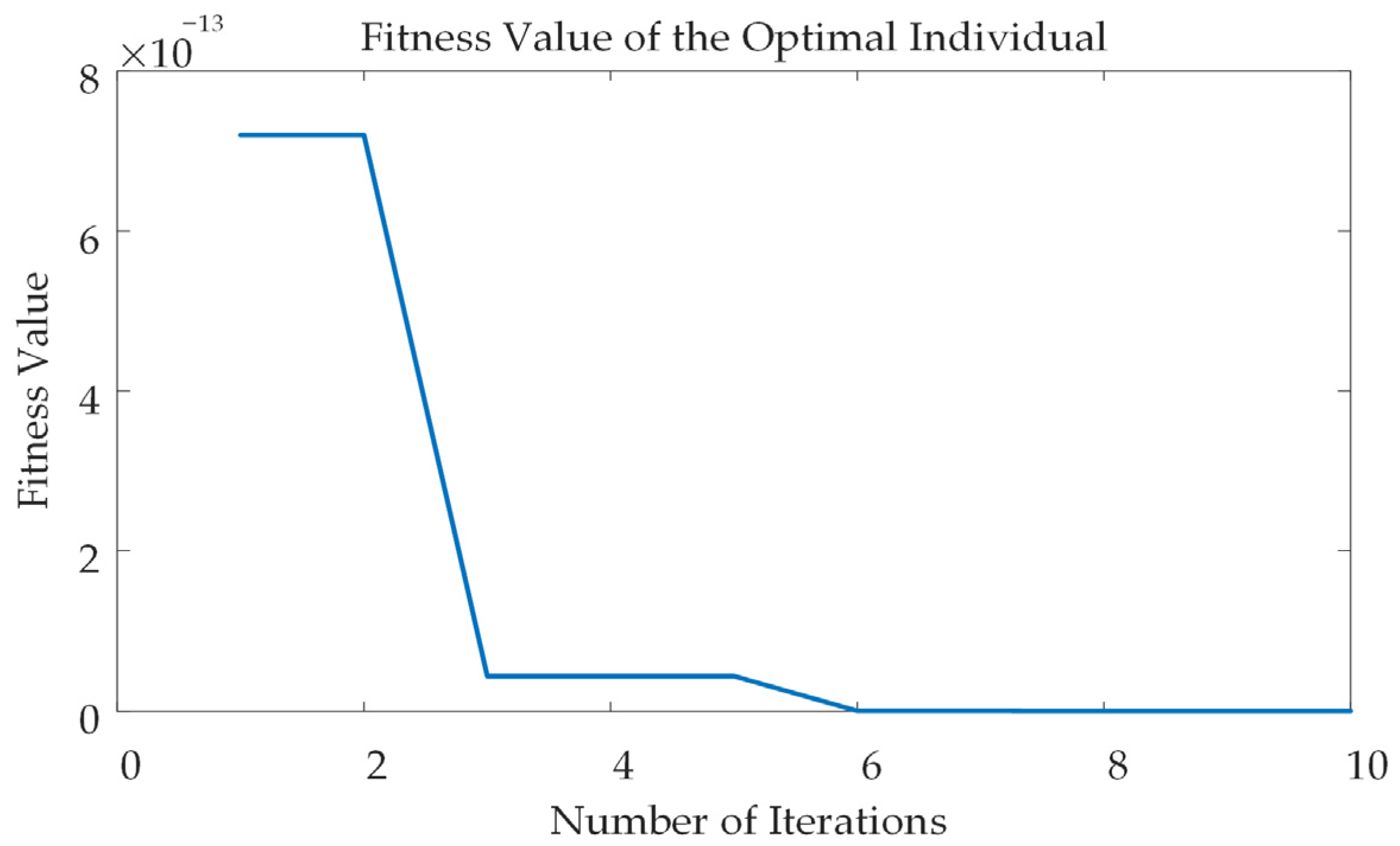
Taking the voltage-speed outer loop of the machine-side FOSMC as an example, e is defined as the difference between the reference speed n* and the actual speed n. Set the inertia factor m = 0.6, the acceleration constants l1 = l2 = 2, the dimension to 5, the particle swarm size to 50, the maximum number of iterations to 10, the minimum fitness value to 10−14, the velocity range to [−1, 1], the ranges of c2, k0, and k1 all to [0, 100], the range of μ to [0, 1], and the range of σ to [0, 1]. Other optimization conditions related to controllers have been placed in Appendix A.
After determining the spatial dimension of the fitness function and the population size, the PSO algorithm is executed to perform the optimization. Through continuous iteration, the particle with the minimum fitness function is identified, and its position in the search space represents the optimal parameters. Finally, the algorithm is checked to see whether it satisfies the constraint conditions: if it does, the optimization terminates and the algorithm outputs the optimal parameters; if it does not, the optimization continues. The variation curve of performance index Z obtained by PSO for the FOSM of the machine-side voltage speed outer-loop is shown in Figure 9.

4.2. Simulation Analysis Under Changing Wind Speeds

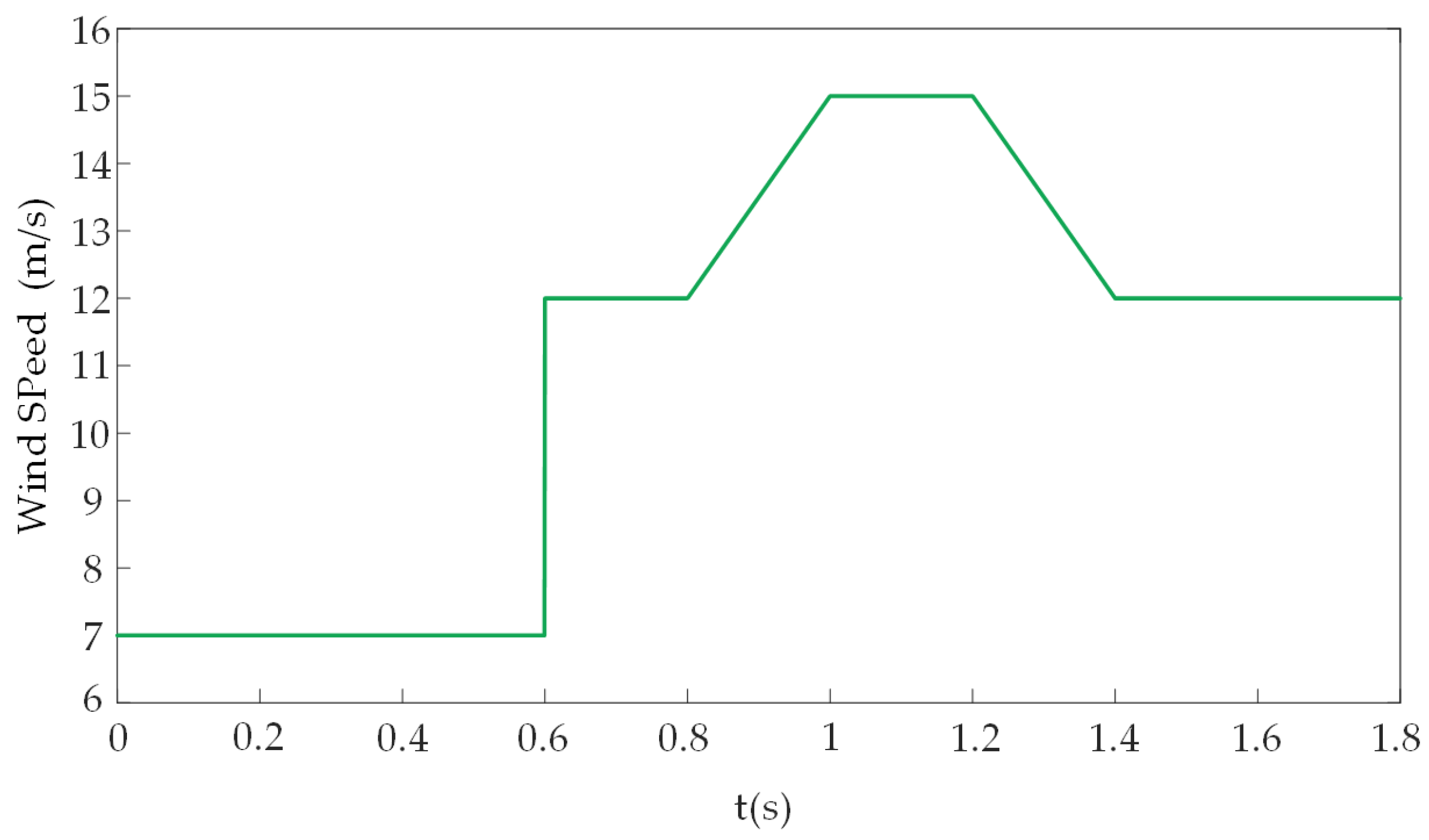
The simulation experiment was performed based on the simulated wind speed presented in Figure 10. The wind speed is initially maintained at 7 m/s, then suddenly increases from 7 m/s to 12 m/s at 0.6 s. It is followed by a gradual rise from 12 m/s at 0.8 s, reaching 15 m/s at 1 s. After maintaining 15 m/s for 0.2 s, it gradually decreases to 12 m/s.
The control parameters relevant to the machine-side converter are tabulated in Table 2.
Table 3 lists the relevant control parameters for grid-side converters.
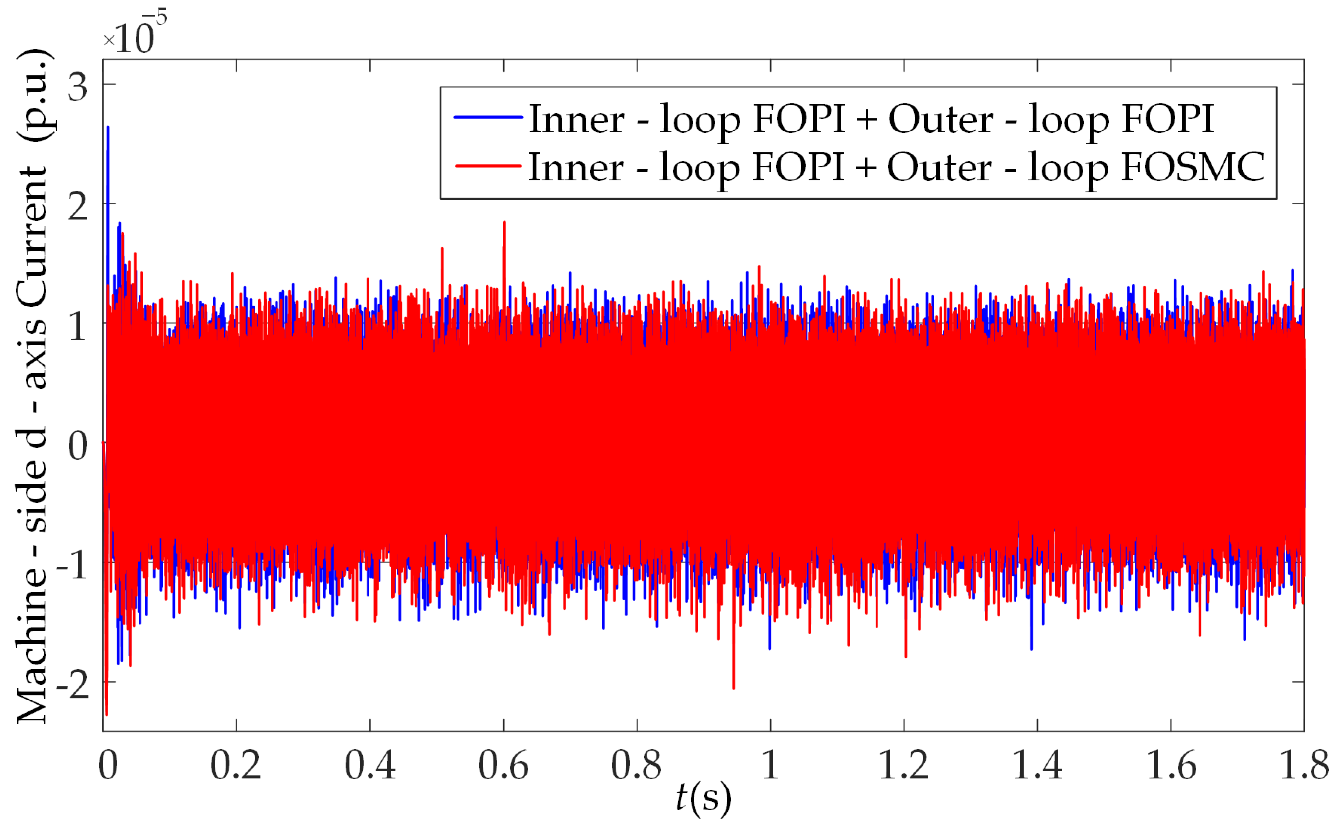
With regard to the machine-side, the corresponding simulation results are shown in Figure 11 and Figure 12.
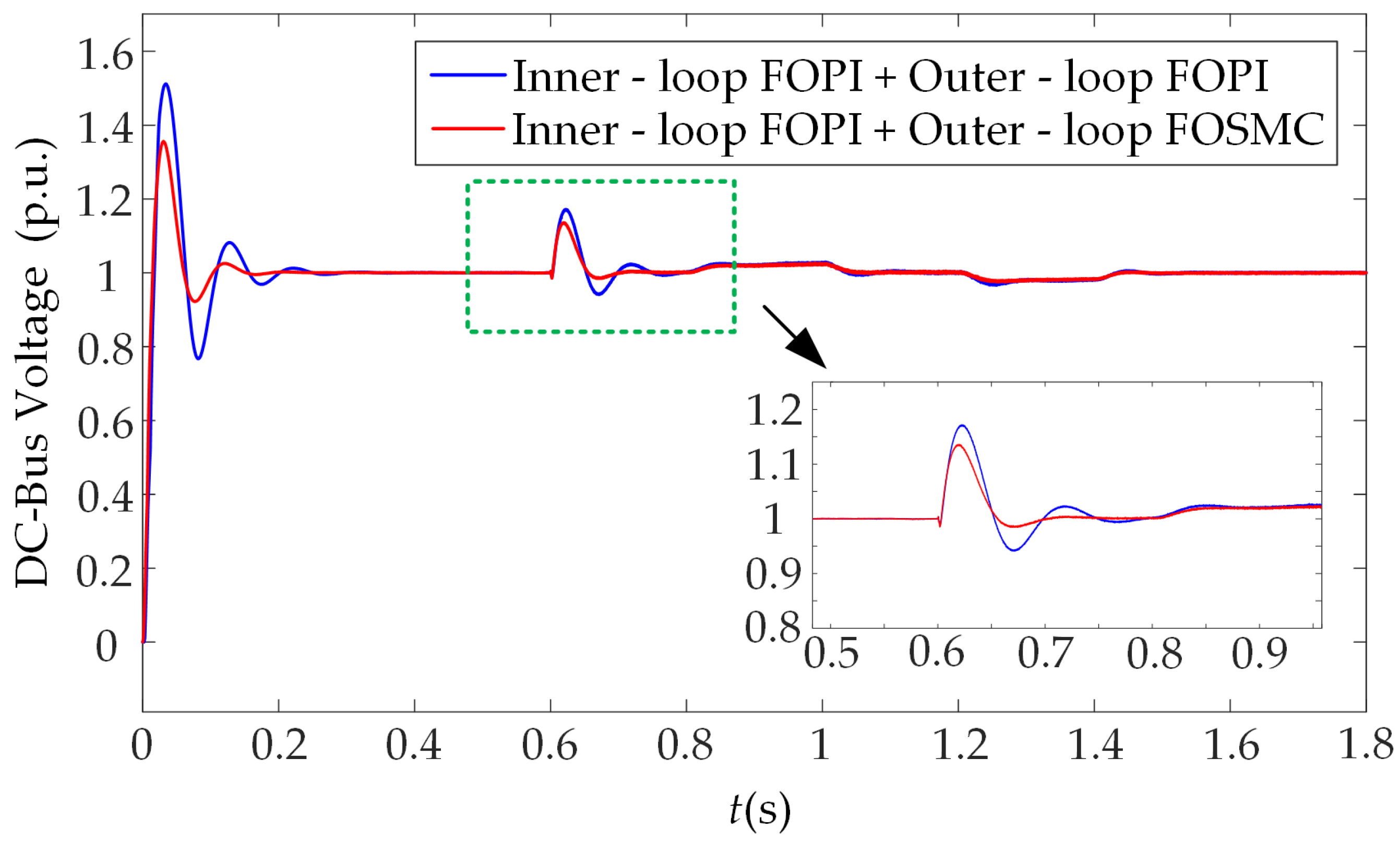
Simulation analysis shows that both control approaches deliver good control performance. As illustrated in Figure 11, both control methods can effectively maintain the d-axis current isd near zero. However, during start-up and at 0.6 s when wind speed changes suddenly, the overshoot of FOSMC is smaller than that of FOPI control. As shown in Figure 12, FOSMC performs better in maintaining DC voltage stability. When wind speed changes suddenly, the DC-bus voltage has an overshoot of 0.135 p.u., while the outer-loop FOPI control has an overshoot of 0.172 p.u.
In contrast, FOSM speed outer-loop control not only enhances the system’s disturbance rejection capability but also improves its stability and dynamic response. It exhibits stronger robustness when subjected to external disturbances (e.g., abrupt wind speed variations), thereby enabling faster attenuation of system fluctuations and consequently minimizing overshoot.
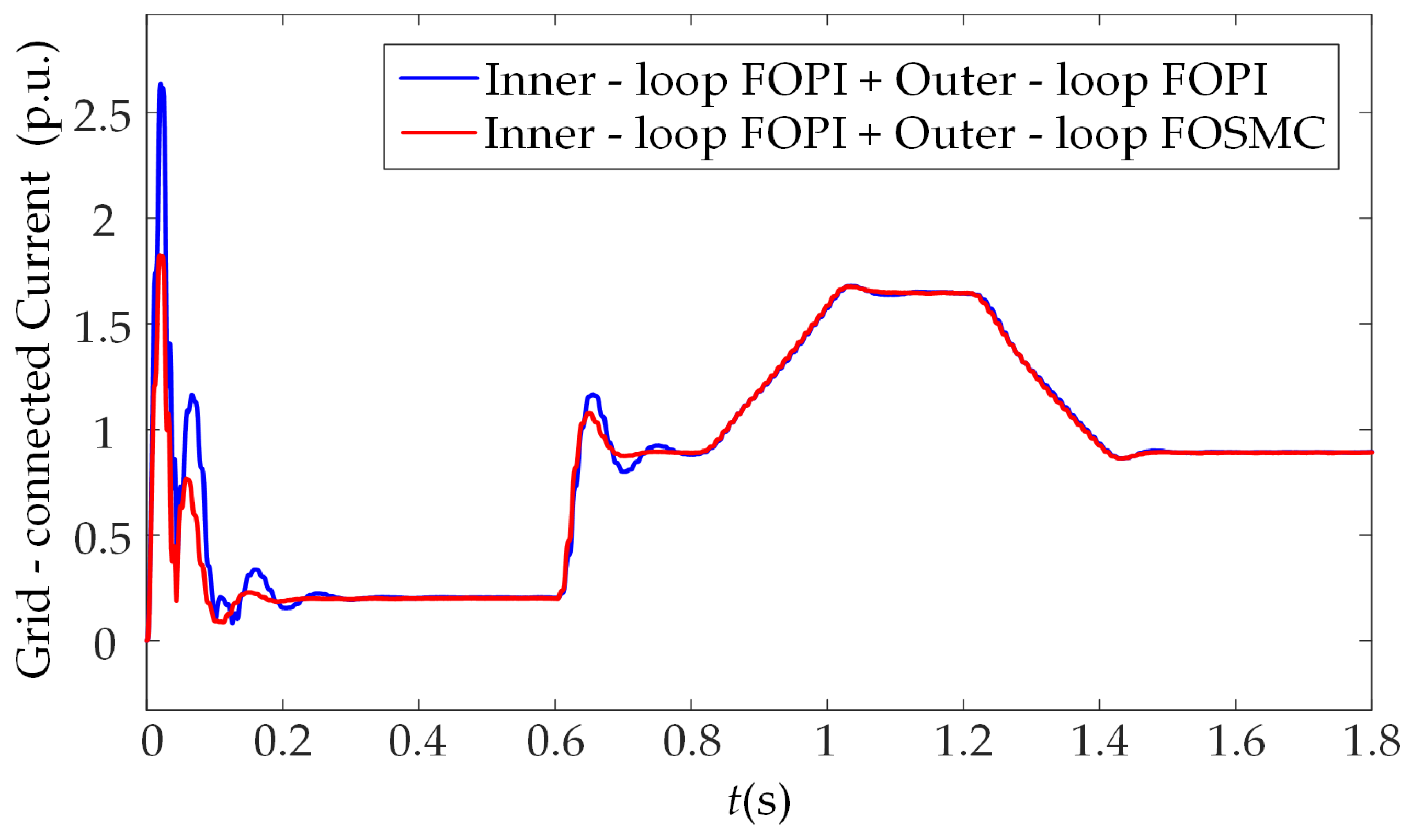
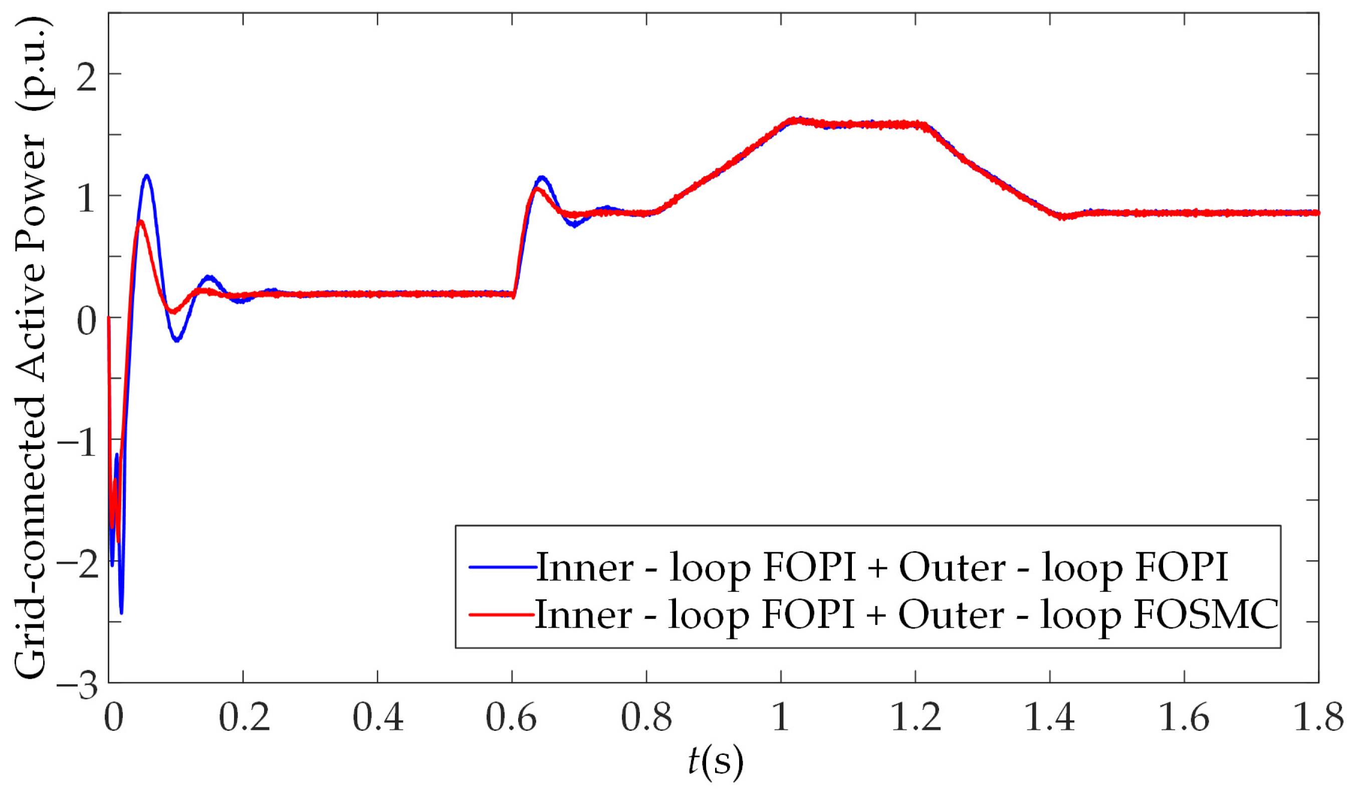
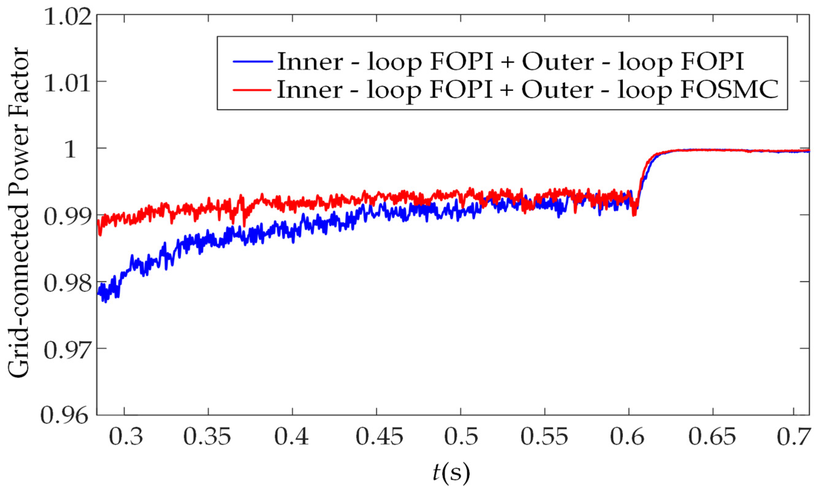
Grid-side simulation results are depicted in Figure 13, Figure 14 and Figure 15, respectively.
As demonstrated in Figure 13, Figure 14 and Figure 15, adopting FOSMC in the voltage outer-loop significantly improves system performance in multiple aspects. During the start-up phase, the grid-connected current converges rapidly to a steady state. In the case of sudden wind speed variations, FOSMC exhibits a maximum current overshoot of 0.187 p.u., which is smaller than FOPI control’s 0.277 p.u., demonstrating superior fluctuation suppression and disturbance resistance. FOSMC also outperforms in power tracking, stabilizing within 0.2 s, and reduces power fluctuation amplitude by 31.74% relative to FOPI under abrupt wind speed changes—mitigating the grid-connection impact of wind energy fluctuations effectively. Moreover, it can quickly stabilize the power factor at 1, contributing to better power quality optimization.

4.3. Simulation Analysis Under Asymmetric Grid Faults

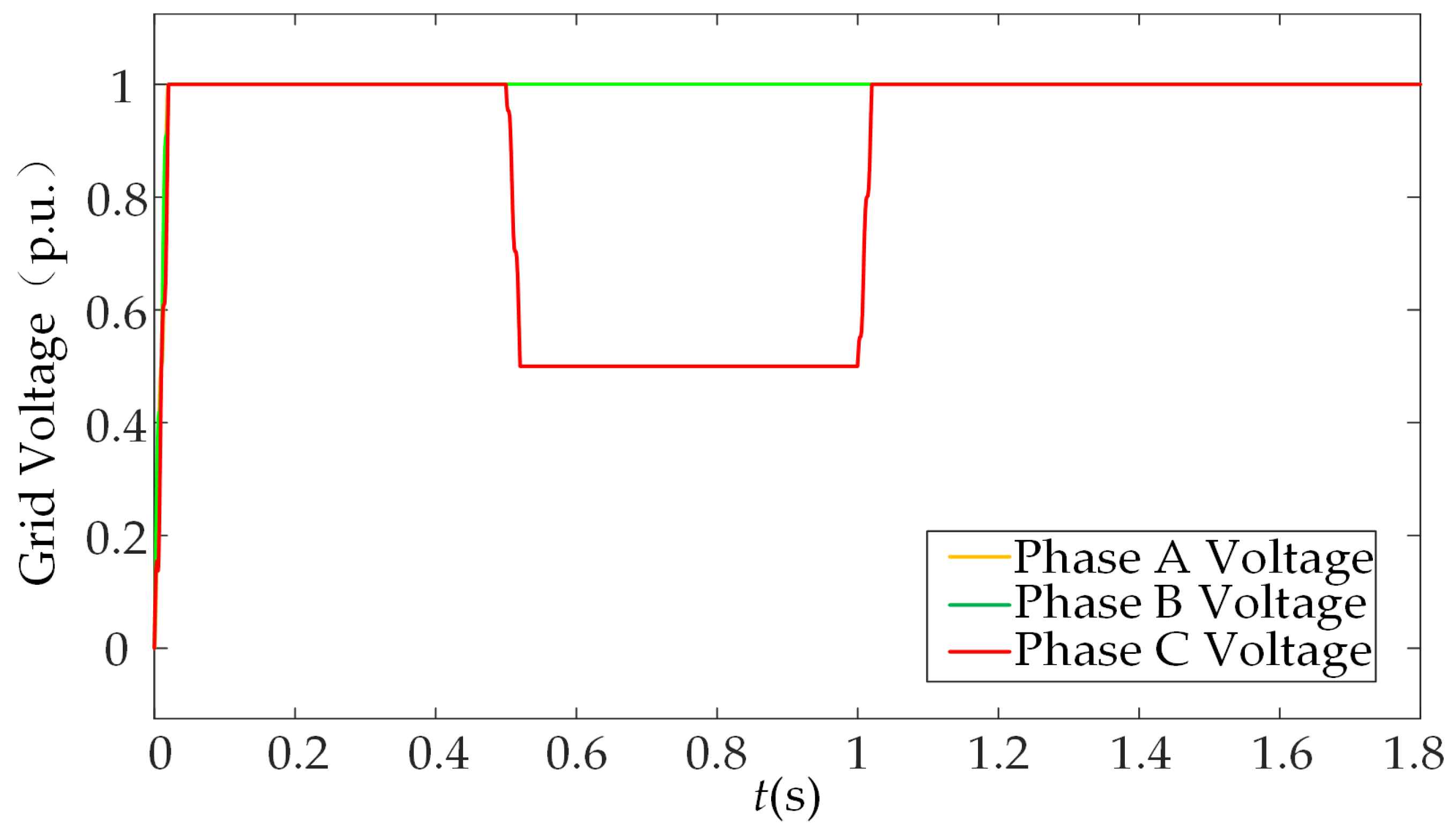
In practical scenarios, the probability of asymmetric faults in the power grid is relatively high. Therefore, this study analyzes the simulation results of different control methods under the same wind speed conditions when a grid fault occurs. The simulation conditions are set as follows: at 0.5 s, the phase-C voltage sags by 50%; at 1 s, the fault is cleared, and the voltage is restored, as depicted in Figure 16.
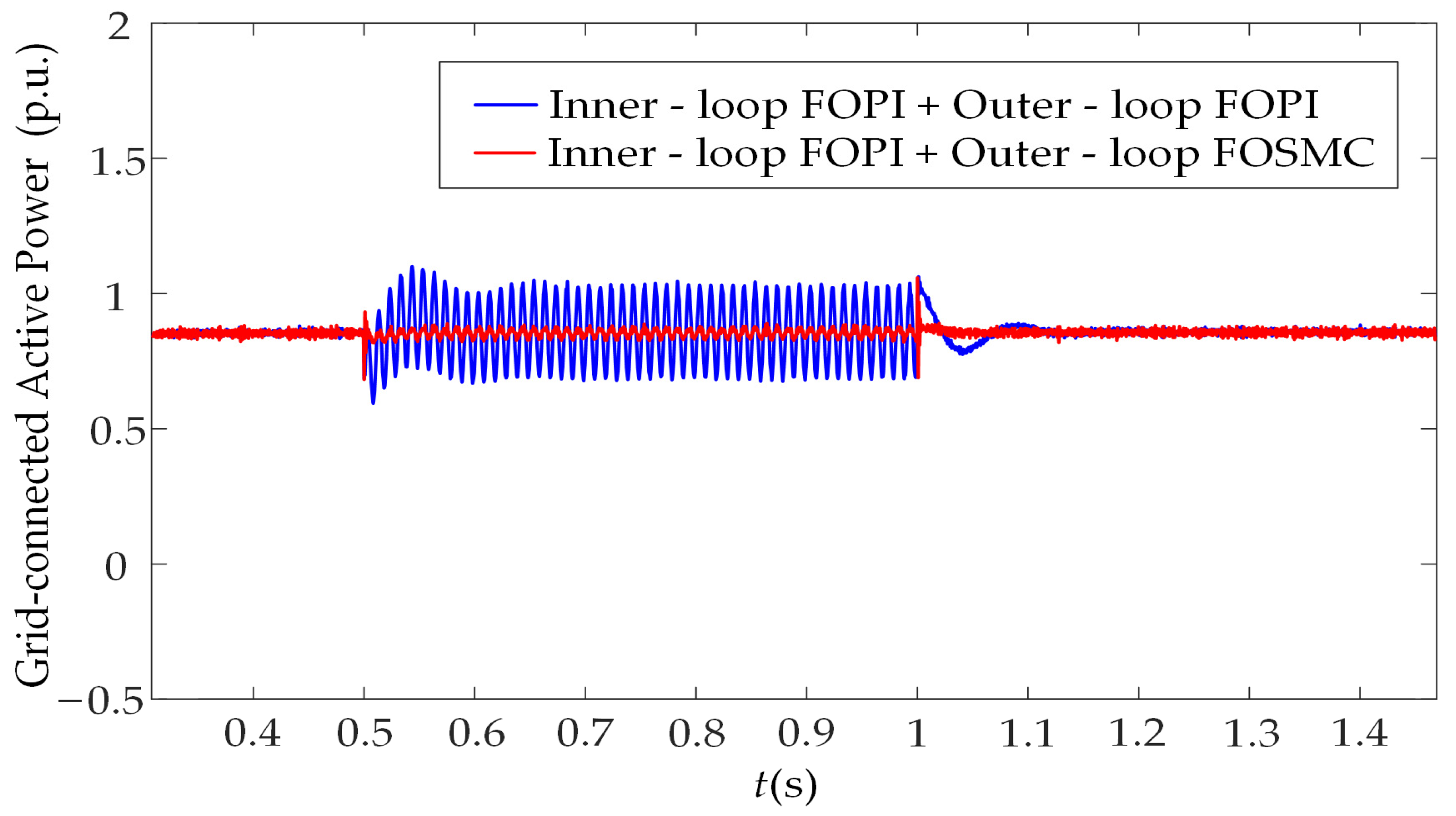
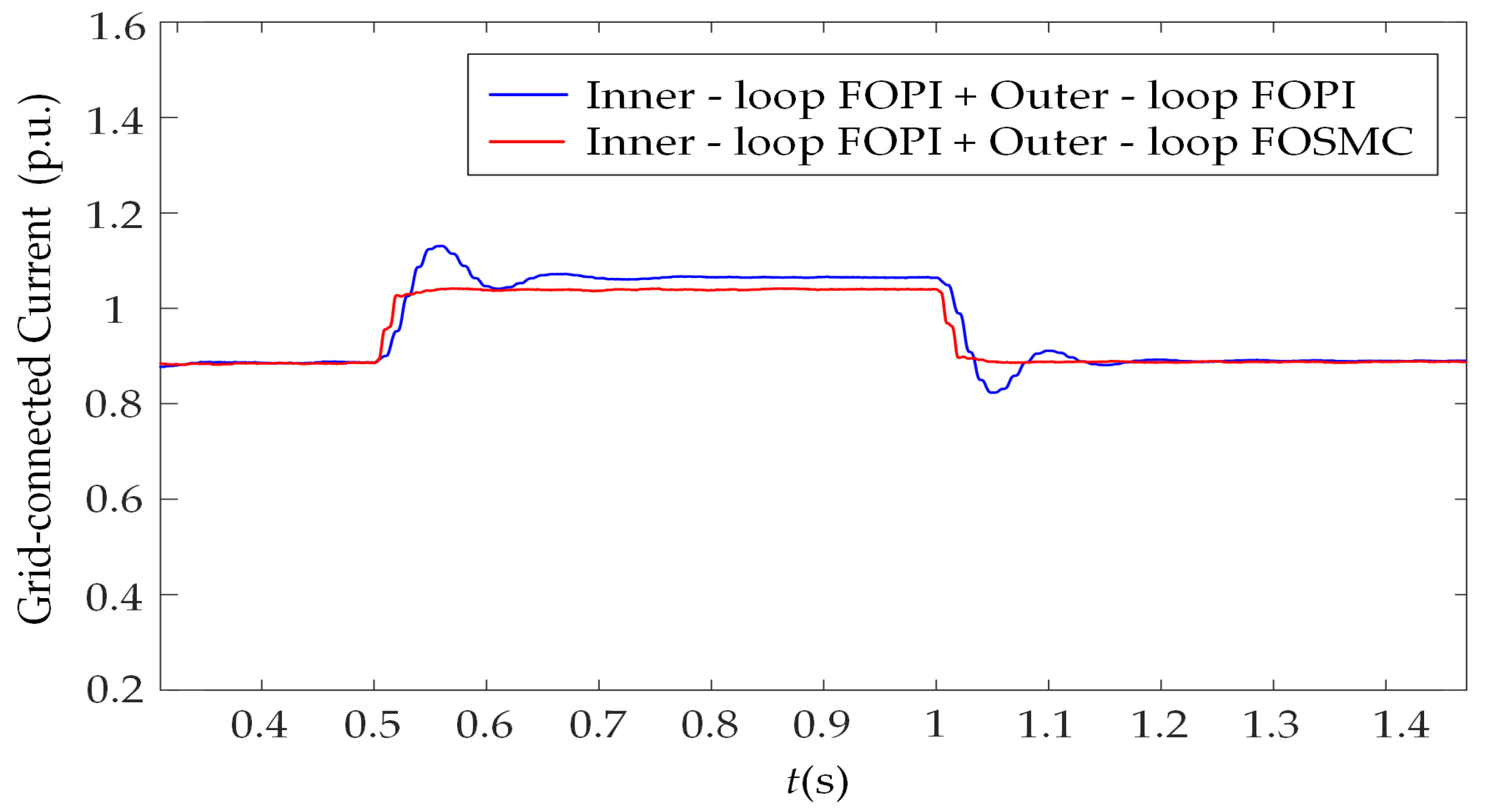
For both the converters, simulation experiments were conducted with two different control strategies to obtain the DC-bus voltage, grid-connected active power, and grid-connected current when asymmetric faults occur in the power grid. The results are presented in Figure 17, Figure 18 and Figure 19.
As demonstrated in Figure 17, during the period before and after the grid voltage fault, both control methods effectively stabilize the DC-bus voltage at approximately 850 V, demonstrating favorable control performance. However, during the grid voltage fault period (0.5 s–1 s), the DC-bus voltage exhibits significant fluctuations under both control methods. When both the machine-side and grid-side outer-loop controls employ FOSMC, the voltage drop is as low as 0.985 p.u., a 65.38% reduction compared to that with both outer-loop FOPI control. Additionally, during voltage recovery, employing FOSMC in the outer loops results in faster recovery speed and higher steady-state accuracy.
Meanwhile, there are obvious differences in the dynamic response of grid-connected active power under the two control methods during the fault, as illustrated in Figure 18. When the outer-loop uses FOPI control, the maximum drop in active power is 30.65%, accompanied by significant oscillations during the drop, indicating insufficient disturbance suppression capability of the control strategy. The overshoot during the recovery phase is 24.1%. In contrast, with FOSMC outer-loop control, the maximum drop in active power is 20.45%, representing a 33.38% reduction in drop magnitude compared to the FOPI control. Meanwhile, the fluctuation amplitude during the fault period is also significantly reduced—indicating that the strong robustness of sliding mode control enables effective disturbance suppression, facilitates faster recovery, and involves no obvious oscillations during the restoration process. Regarding the grid-connected current of the two control methods at fault occurrence and clearance, as shown in Figure 19, FOSMC exhibits a smaller overshoot than FOPI control.
In summary, FOSMC integrates fractional-order calculus with the robustness of sliding mode control, and is comparatively superior to FOPI control in terms of dynamic response, steady-state accuracy, and anti-interference capability.

4.4. Robustness Test of the FOSM Controller

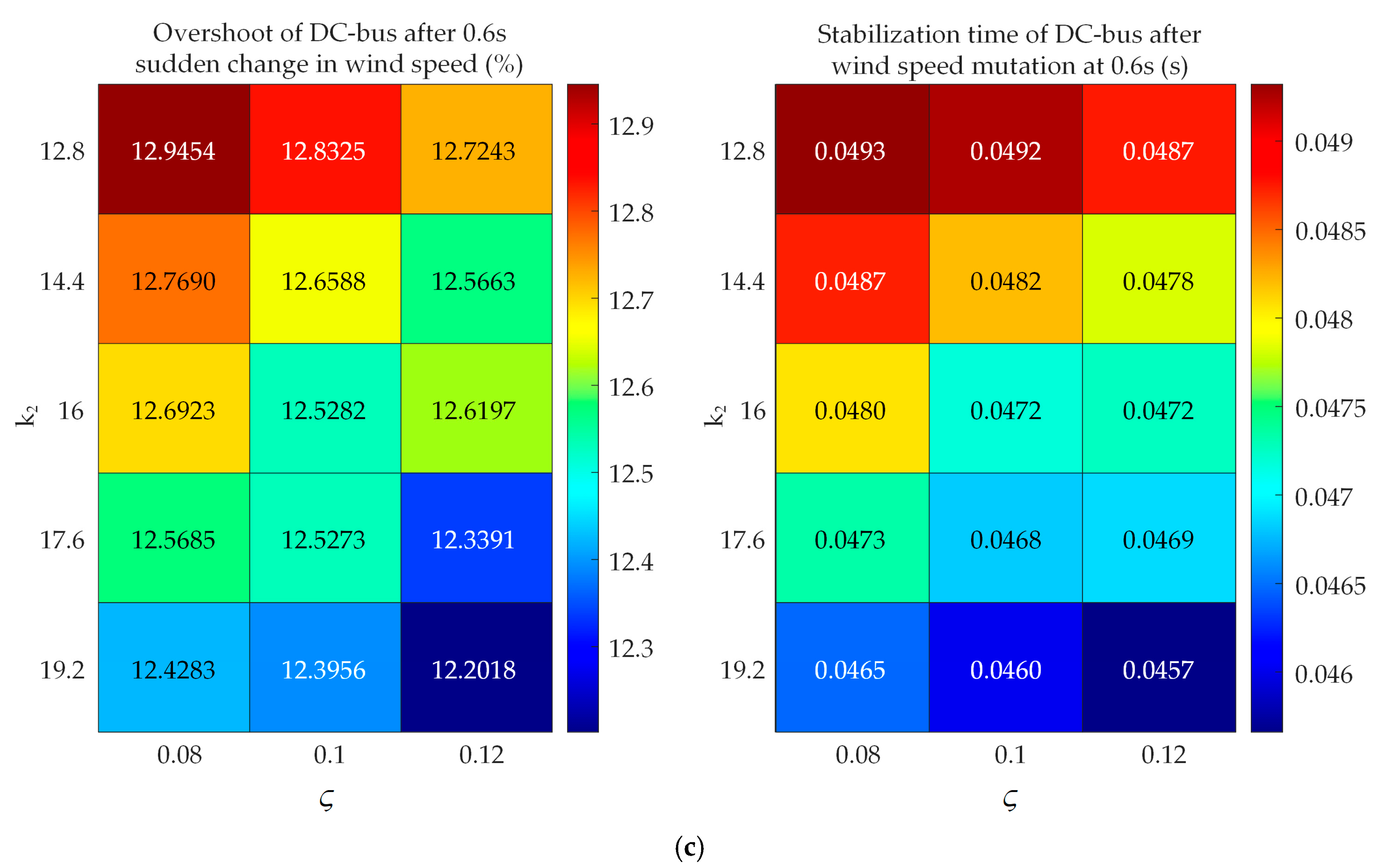
Taking the grid-side voltage outer-loop FOSM controller as an example, this paper verifies the controller’s robustness under wind speed variation and parameter uncertainty by changing system physical parameters and control parameters. Specifically, the machine-side inductance is perturbed by +10%, the grid-side inductance by −10%, while the core gain k2 of the sliding mode switching term and the fractional-order parameters ζ and τ are varied within a ±20% range. Key indicators analyzed include the DC bus voltage overshoot, settling time (with an error ≤ 0.5%), and the average of absolute errors in the stable phase at the later stage of simulation when wind speed suddenly changes at 0.6 s. The heat map of transient indicators for DC bus voltage under different parameter combinations is shown in Figure 20.
It can be seen from Figure 20 that under parameter uncertainty, the DC-bus voltage overshoot fluctuates relatively smoothly, with no local sudden increase areas. The controller can effectively suppress the overshoot amplitude of the DC-bus voltage under parameter disturbances. Meanwhile, the distribution of the DC-bus voltage stabilization time is also relatively concentrated; even with parameter deviations, the controller can still quickly restore the system to a steady state.
The absolute value of the steady-state error of the DC-bus voltage under different parameter combinations is shown in Figure 21.
It can be seen from Figure 21 that under different parameter combinations, the absolute value of the DC-bus voltage steady-state error is not only small in value, but also has a small fluctuation amplitude when parameters change, fully demonstrating that the FOSM controller has strong adaptability under parameter disturbances.
Overall, the FOSM controller designed in this paper exhibits good robustness within the tested parameter range.

5. Conclusions

This study focuses on a fractional-order permanent magnet direct-drive wind power generation system, which integrates a fractional-order capacitor installed on the DC-bus and an FOLCL filter. Based on the system’s mathematical model, a dual closed-loop control structure was designed: the machine-side rectifier employs an FOSM speed outer loop paired with a dq-axis decoupled FOPI current inner loop, while the grid-side converter adopts a FOSM voltage outer loop paired with a dq-axis decoupled FOPI current inner loop. The parameters of the FOSM controllers were tuned using the PSO method, and the validity of the theoretical research was subsequently verified via digital simulations. Key findings of this study are as follows:
(1)
Compared with the traditional FOPI outer-loop control, the FOSM outer-loop control demonstrates superior dynamic and static performance. In the presence of disturbances such as sudden wind speed fluctuations and grid voltage faults, FOSMC not only achieves lower overshoot and faster response speed but also exhibits notable superiority in terms of steady-state accuracy and anti-interference ability, thus providing a more dependable control support for the efficient grid integration of permanent magnet direct-drive wind power systems.
(2)
When both the speed outer-loop and the voltage outer-loop employ FOSMC, the system’s performance improvement under different disturbance scenarios exhibits distinct focus areas. Applying FOSMC in the speed outer-loop can enhance the dynamic regulation capability for the d-axis current and speed; adopting FOSMC in the voltage outer-loop can significantly improve the stability of the DC-bus voltage, as well as the control accuracy of grid-connected current and power. Meanwhile, under complex operating conditions such as grid voltage faults, the robustness advantage of FOSMC can effectively suppress system fluctuations and facilitate faster system recovery.
However, this study still has some limitations:
(1)
The permanent magnet direct-drive generator studied in this paper is an integer-order model, and this research focuses on the basic effectiveness verification of the FOSMC strategy in the fractional-order permanent magnet direct-drive wind power grid-connected system. Therefore, in simulation modeling, only some delay links of the system (such as pulse width modulation delay and communication transmission delay) are taken into account, with the focus on verifying the control performance of the control strategy under wind speed variation and grid voltage faults. This study does not consider noise and quantization effects for the time being and does not extend to the influence of nonlinear disturbances in engineering scenarios.
(2)
This study focuses on the working conditions of wind speed changes and single-phase grid voltage sags, without considering more complex composite fault conditions, such as “wind speed change + grid fault”. The control performance under multiple external disturbance conditions has not been verified, and there is a certain limitation in the coverage of working conditions.
(3)
The selection of relevant parameters for FOSMC is optimized according to the working conditions set in this study, and the adaptive matching between working condition parameters and control parameters has not been achieved. When the working condition range is beyond the scope of this study, the parameters need to be re-tuned, resulting in a lack of cross-working condition universality.
Nonetheless, the applicability of the FOSMC method designed in this paper also has some limitations:
(1)
The proposed FOSMC can achieve smooth power output by quickly adjusting the electromagnetic torque above the rated wind speed. However, in the low-wind-speed range, due to the small output torque of the permanent magnet synchronous generator, the chattering suppression effect of FOSMC will weaken as the signal-to-noise ratio of the torque signal decreases, and there are certain limitations.
(2)
The algorithm proposed in this paper can suppress torque ripple by virtue of the fast convergence characteristic of FOSM when the single-phase voltage sag is 50%. But when the voltage sag is deep, the switching gain of the fractional-order sliding mode surface needs to be greatly increased to maintain control stability. At this time, the chattering phenomenon of the algorithm will be significantly aggravated, and its applicability in deep sag scenarios is limited.
Future research of this study can be carried out in the following aspects (but not limited to):
(1)
For the permanent magnet synchronous generator in the fractional-order permanent magnet direct-drive wind power system investigated in this paper—currently modeled using an integer-order mathematical framework—it is necessary to conduct in-depth studies on its fractional-order mathematical model.
(2)
This paper employs FOPI control for the inner-loop control of back-to-back converters. In subsequent work, FOSMC can be applied to the inner-loop control for comparative analysis. Additionally, based on (1), FOSMC can be used for full-system control and then compared and analyzed in detail with other fractional-order control strategies.
(3)
Noise and quantization effects play a crucial role in practical system performance. In future work, we will introduce noise to analyze its impact on the control accuracy of FOSMC; explore the coupling mechanism between quantization effects and the dynamic characteristics of fractional-order capacitors; and verify the anti-disturbance capability of the proposed control strategy when such disturbances are considered through comparative simulations, thereby further enhancing the engineering applicability of the method.

Author Contributions

Conceptualization, J.X.; data curation, Y.L. (Yue Lan), C.W., B.L., Y.L. (Yingheng Li) and Y.X.; formal analysis, Y.L. (Yue Lan); investigation, Y.L. (Yue Lan); methodology, J.X.; project administration, J.X.; resources, J.X., C.W., B.L., Y.L. (Yingheng Li) and Y.X.; software, Y.L. (Yue Lan); supervision, J.X.; validation, Y.L. (Yue Lan); visualization, Y.L. (Yue Lan); writing—original draft, Y.L. (Yue Lan); writing—review and editing, J.X. and Y.L. (Yue Lan) All authors have read and agreed to the published version of the manuscript.

Funding

This research received no external funding.

Data Availability Statement

The original contributions presented in the study are included in the article; further inquiries can be directed to the corresponding authors.

Conflicts of Interest

The authors declare no conflicts of interest.

Appendix A

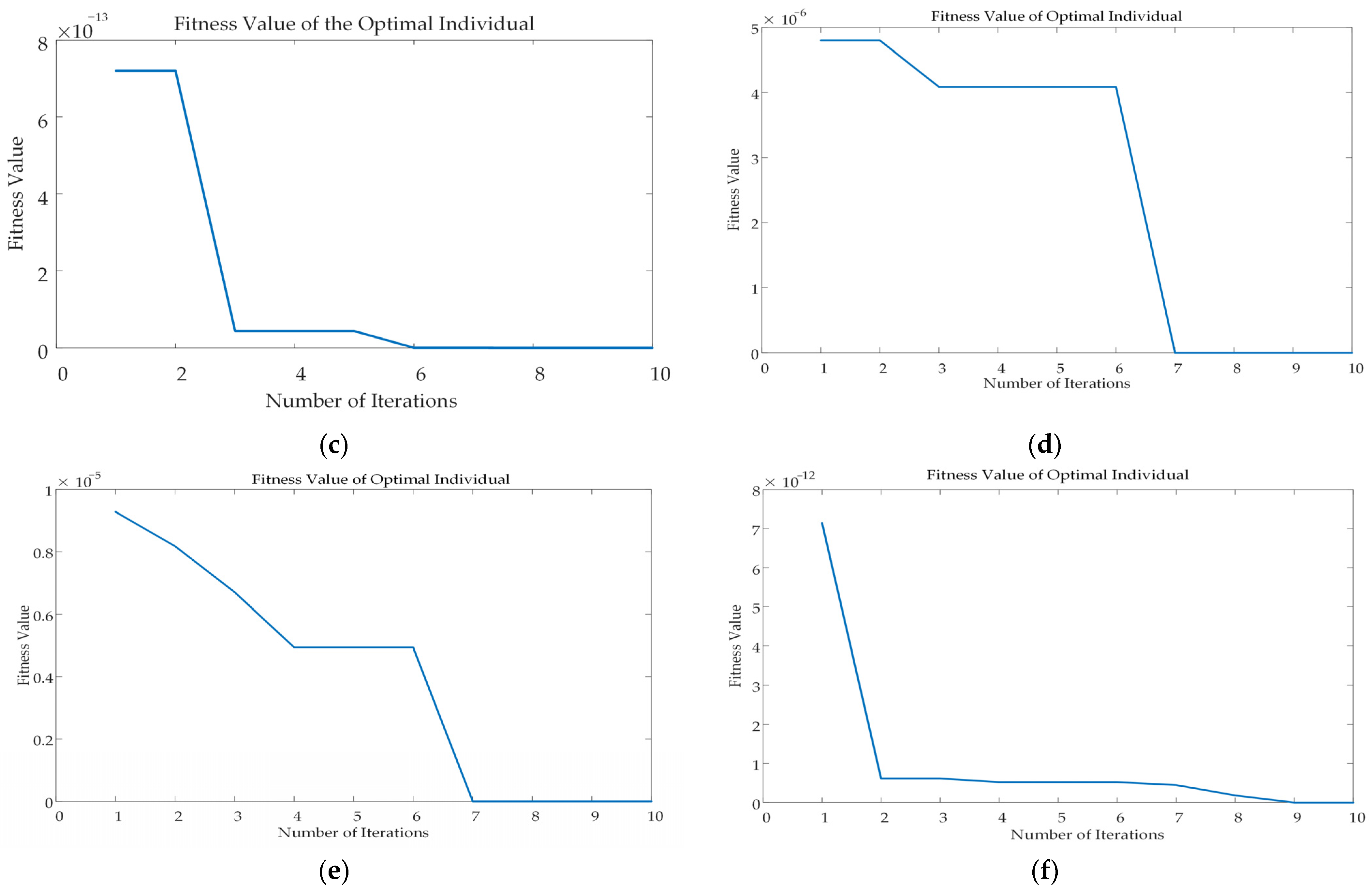
Information related to the particle swarm optimization algorithm, such as the state objective function, parameter boundaries, population size, number of iterations, and stopping criteria, is presented in Table A1 and Table A2. Among them, the objective function is integral of time-weighted absolute error (ITAE), the number of iterations is 10 and the population size is 50.
Table A1. Machine-side parameter.
LoopParameterParameter BoundariesStopping Criteria
FOPI current loopkp[0, 100]10−6
ki[800, 1200]
η[0, 1]
FOPI speed loopkp[0, 100]10−6
ki[2800, 3500]
η′[0, 1]
FOSMC speed loopμ[0, 1]10−14
σ[0, 1]
k0[0, 100]
k1[0, 100]
Table A2. Grid-side parameter.
LoopParameterParameter BoundariesStopping Criteria
FOPI current loopkp0[0, 100]10−6
ki0[800, 1200]
η0[0, 1]
FOPI voltage loopkp0[0, 10]10−6
ki0[0, 100]
η0[0, 1]
FOSMC voltage loopς[0, 1]10−14
τ[0, 1]
k2[0, 50]
k3[50, 150]
The relevant convergence graph is shown in Figure A1.
Figure A1. Convergence graph of the optimization algorithm: (a) Convergence graph of the machine-side FOPI current loop; (b) Convergence graph of the machine-side FOPI speed loop; (c) Convergence graph of the machine-side FOSMC speed loop; (d) Convergence graph of the grid-side FOPI current loop; (e) Convergence graph of the grid-side FOPI voltage loop; (f) Convergence graph of the grid-side FOSMC voltage loop.
Machines 13 00928 g0a1aMachines 13 00928 g0a1b

References

  1. Ma, X.; Li, M.; Li, W.; Liu, Y. Overview of offshore wind power technologies. Sustainability 2025, 17, 596. [Google Scholar] [CrossRef]
  2. Mossa, M.A.; Mohamed, R.A.; Al-Sumaiti, A.S. Performance Enhancement of a Grid Connected Wind Turbine Based PMSG Using Effective Predictive Control Algorithm. IEEE Access 2025, 13, 64160–64185. [Google Scholar] [CrossRef]
  3. Rausell, E.; Arnaltes, S.; Rodríguez, J.L.; Lafoz, M.; Navarro, G. Control of wind energy conversion systems with permanent magnet synchronous generator for isolated green hydrogen production. Int. J. Hydrogen Energy 2025, 107, 241–251. [Google Scholar] [CrossRef]
  4. Liu, D.; Han, J.; Chen, G.; Cheng, Y.; Liang, X.; Song, C. Fuzzy self-tuning fractional order PD permanent magnet synchronous motor speed control based on torque compensation. Sci. Rep. 2025, 15, 2141. [Google Scholar] [CrossRef]
  5. Zhang, B.; Shu, X. Fractional-Order Electrical Circuit Theory; Springer: Singapore, 2022. [Google Scholar]
  6. Zhang, L.; Kartci, A.; Elwakil, A.; Bagci, H.; Salama, K.N. Fractional-order inductor: Design, simulation, and implementation. IEEE Access 2021, 9, 73695–73702. [Google Scholar] [CrossRef]
  7. Mijat, N.; Jurisic, D.; Moschytz, G.S. Analog modeling of fractional-order elements: A classical circuit theory approach. IEEE Access 2021, 9, 110309–110331. [Google Scholar] [CrossRef]
  8. Zheng, Z.; Ma, F.J.; Wei, Y.F. Fractional-order modeling and simulation analysis of single-phase PWM rectifier. J. Syst. Simul. 2017, 29, 784. [Google Scholar]
  9. Li, X.C.; Hou, L.L.; Luo, X.L.; Xu, J.H. Fractional-order modeling and controller design of three-phase inverter grid-connected system. Acta Energiae Solaris Sin. 2023, 44, 415–424. [Google Scholar]
  10. Li, X.C.; Luo, X.L.; Hou, L.L.; Xu, J.H. Grid-side control research of wind power generation based on fractional-order LCL filter. Acta Energiae Solaris Sin. 2022, 43, 383–391. [Google Scholar]
  11. Aarif, M.; Joshi, D.; Jangid, R.; Sharma, S.S. Grid Power Smoothing Management for Direct-Drive PMSG Variable-Speed Wind Energy Conversion System with Multilevel Converter. In ICT Infrastructure and Computing: Proceedings of ICT4SD 2022; Springer Nature Singapore: Singapore, 2022; pp. 19–28. [Google Scholar]
  12. Yu, J.; Ouyang, J.; Zhang, A.; Chen, J. Modeling of dynamic control error and emergency frequency control for direct-drive PMSG-based wind turbine under grid fault. IEEE Trans. Sustain. Energy 2024, 15, 1690–1702. [Google Scholar] [CrossRef]
  13. Vu, N.T.T.; Nguyen, H.D.; Nguyen, A.T. Reinforcement learning-based adaptive optimal fuzzy MPPT control for variable speed wind turbine. IEEE Access 2022, 10, 95771–95780. [Google Scholar] [CrossRef]
  14. Bu, W.; Guo, S.; Fan, Z.; Li, J. Improved Adaptive PI-like Fuzzy Control Strategy of Permanent Magnet Synchronous Motor. Energies 2025, 18, 362. [Google Scholar] [CrossRef]
  15. Pathak, D.; Bhati, S.; Gaur, P. Fractional-order nonlinear PID controller based maximum power extraction method for a direct-driven wind energy system. Int. Trans. Electr. Energy Syst. 2020, 30, e12641. [Google Scholar] [CrossRef]
  16. Pathak, D.; Gaur, P. Output power control of wind energy system by tip speed ratio control using fractional PI β D α controller. Int. J. Inf. Technol. 2021, 13, 299–305. [Google Scholar]
  17. Benbouhenni, H.; Bizon, N.; Colak, I.; Thounthong, P.; Takorabet, N. Application of fractional-order PI controllers and neuro-fuzzy PWM technique to multi-rotor wind turbine systems. Electronics 2022, 11, 1340. [Google Scholar] [CrossRef]
  18. Feyzi, M.; Roozbehani, S.; Ghaseminejad Liasi, S.; Kordkandi, R.D. Real-Time Fault Ride Through Capability Improvement of PMSG-Wind Turbine Based on Robust Fractional Order Sliding Mode Control. Optim. Control. Appl. Methods 2025, 46, 859–874. [Google Scholar] [CrossRef]
  19. Ferhat, N.; Aounallah, T.; Essounbouli, N.; Hamzaoui, A.; Bouchafaa, F. Fractional Adaptive Fuzzy Sliding Mode Control Algorithm for Permanent Magnet Synchronous Generators. In Proceedings of the 2021 International Conference on Control, Automation and Diagnosis (ICCAD), Grenoble, France, 3–5 November 2021; IEEE: Washington, DC, USA, 2021; pp. 1–6. [Google Scholar]
  20. Qu, X.; Zhang, S.; Peng, C. Model-Free Adaptive Fast Integral Terminal Sliding Mode Control for Permanent Magnet Synchronous Motor with Position Error Constraint. World Electr. Veh. J. 2025, 16, 341. [Google Scholar] [CrossRef]
  21. Wu, Z.; Zhuang, J.; Liu, B.; Yang, P. Control method for permanent magnet synchronous motor based on fractional active disturbance rejection. Trans. Inst. Meas. Control. 2023, 45, 2352–2363. [Google Scholar] [CrossRef]
  22. Wang, W. Simulation Study on Permanent Magnet Direct-Drive Motor Based on Fractional-Order PID Control. Electr. Meas. Instrum. 2016, 53 (Suppl. 1), 223–226. [Google Scholar]
  23. Gao, P.; Zhang, G.; Lv, X. Model-free hybrid control with intelligent proportional integral and super-twisting sliding mode control of PMSM drives. Electronics 2020, 9, 1427. [Google Scholar] [CrossRef]
  24. Zaihidee, F.M.; Mekhilef, S.; Mubin, M. Application of fractional order sliding mode control for speed control of permanent magnet synchronous motor. IEEE Access 2019, 7, 101765–101774. [Google Scholar] [CrossRef]
  25. Ahmed, T.; Waqar, A.; Elavarasan, R.M.; Imtiaz, J.; Premkumar, M.; Subramaniam, U. Analysis of fractional order sliding mode control in a D-STATCOM integrated power distribution system. IEEE Access 2021, 9, 70337–70352. [Google Scholar] [CrossRef]
  26. Jiang, L.J.; Wang, X.Y.; Su, J.; Zhang, Z.T. Fuzzy Fractional-Order Control for Maximum Power Point Tracking of Permanent Magnet Synchronous Wind Power Generation System. Mod. Electr. Power 2024, 41, 230–239. [Google Scholar]
  27. Prajzendanc, P.; Kreischer, C. A Review of New Technologies in the Design and Application of Wind Turbine Generators. Energies 2025, 18, 4082. [Google Scholar] [CrossRef]
  28. Lin, L.; He, Y.; Zhou, J.H.; Chen, H.Z.; Liu, Y.L.; Chen, H.W. Modeling and Simulation of Direct-Drive Permanent Magnet Synchronous Wind Turbine Generator-Side System. Electr. Drive 2020, 50, 73–76. [Google Scholar]
  29. Zhang, M.; He, G.Q.; Zhao, H.X.; Zhang, K.S. Modeling and Simulation of Direct-Drive Permanent Magnet Synchronous Wind Turbine Units. Electr. Power 2008, 41, 79–84. [Google Scholar]
  30. Xu, J.; Tang, S.; He, G.; Gong, Z.; Lin, G.; Liu, J. Modeling and Control Research of Fractional-Order Cascaded H-Bridge Multilevel STATCOM. Fractal Fract. 2024, 8, 392. [Google Scholar] [CrossRef]
  31. Wang, H.B.; Zhou, B.; Fang, S.C. Sliding Mode Control of Permanent Magnet Synchronous Motor Speed Regulation System. Trans. China Electrotech. Soc. 2009, 24, 71–77. [Google Scholar]
  32. Abdolrasol, M.G.M.; Hannan, M.A.; Hussain, S.M.S.; Ustun, T.S. Optimal PI controller based PSO optimization for PV inverter using SPWM techniques. Energy Rep. 2022, 8, 1003–1011. [Google Scholar] [CrossRef]
  33. Wang, X.; Guo, W.; Wei, M. Parameter Tuning of Fractional-Order PID Sliding Mode Control Based on Particle Swarm Optimization. Meas. Control. Technol. 2017, 36, 63–66. [Google Scholar]
Figure 1. Primary circuit of a fractional-order permanent magnet direct-drive wind power generation system.
Machines 13 00928 g001
Figure 2. Converter topology.
Machines 13 00928 g002
Figure 3. FOLCL topology diagram.
Machines 13 00928 g003
Figure 4. Control block diagram of the machine-side converter with FOSMC speed outer-loop and FOPI current inner-loop.
Machines 13 00928 g004
Figure 5. Fractional-order current inner-loop controller.
Machines 13 00928 g005
Figure 6. Block diagram of d-axis current control after decoupling.
Machines 13 00928 g006
Figure 7. Control block diagram of the grid-side converter with FOSMC voltage outer-loop and FOPI current inner-loop.
Machines 13 00928 g007
Figure 8. Particle swarm optimization algorithm design process.
Machines 13 00928 g008
Figure 9. Response curve of performance index Z.
Machines 13 00928 g009
Figure 10. Wind speed curve.
Machines 13 00928 g010
Figure 11. Machine-side d-axis current comparison chart. Operating point: wind speed varies as shown in Figure 10, grid normal operation.
Machines 13 00928 g011
Figure 12. DC-bus voltage comparison chart. Operating point: wind speed varies as shown in Figure 10, grid normal operation.
Machines 13 00928 g012
Figure 13. Grid-connected current comparison chart. Operating point: wind speed varies as shown in Figure 10, grid normal operation.
Machines 13 00928 g013
Figure 14. Grid-connected active power comparison chart. Operating point: wind speed varies as shown in Figure 10, grid normal operation.
Machines 13 00928 g014
Figure 15. Grid-connected power factor comparison chart. Operating point: wind speed varies as shown in Figure 10, grid normal operation.
Machines 13 00928 g015
Figure 16. Grid voltage.
Machines 13 00928 g016
Figure 17. DC-bus voltage comparison chart. Operating point: Wind speed is 12 m/s, and phase C voltage drops by 50%.
Machines 13 00928 g017
Figure 18. Grid-connected active power comparison chart. Operating point: Wind speed is 12 m/s, and phase C voltage drops by 50%.
Machines 13 00928 g018
Figure 19. Grid-connected current comparison chart. Operating point: Wind speed is 12 m/s, and phase C voltage drops by 50%.
Machines 13 00928 g019
Figure 20. Heat map of DC bus voltage transient indicators under different parameter combinations: (a) Heat map of transient indices when τ is 0.695; (b) Heat map of transient indices when τ is 0.869; (c) Heat map of transient indices when τ is 1.043.
Machines 13 00928 g020aMachines 13 00928 g020b
Figure 21. Heat map of the absolute value of the DC-bus voltage steady-state error under different parameter combinations: (a) Heat map when τ is 0.695; (b) Heat map when τ is 0.869; (c) Heat map when τ is 1.043.
Machines 13 00928 g021
Table 1. Related system parameters.
ParameterValue
udc850 V
α0.85
β0.95
L10.72 mH/s1−α
L20.72 mH/s1−α
Cdc0.01 F/s1−β
C0.001 F/s1−β
p10
J5 kg·m2
Rs0.045 Ω
ψf1.832 Wb
Lsd, Lsq0.755 mH/s1−α
Table 2. Machine-side configuration parameters.
LoopParameterValue
FOPI current loopkp50
ki1000
η0.8
FOPI speed loopkp20
ki3000
η′0.9
FOSMC speed loopμ0.976
σ0.142
k063
k159
Table 3. Grid-side configuration parameters.
LoopParameterValue
FOPI current loopkp080
ki01000
η00.78
FOPI voltage loopkp00.5
ki060
η00.95
FOSMC voltage loopς0.1
τ0.869
k216
k3100
Disclaimer/Publisher’s Note: The statements, opinions and data contained in all publications are solely those of the individual author(s) and contributor(s) and not of MDPI and/or the editor(s). MDPI and/or the editor(s) disclaim responsibility for any injury to people or property resulting from any ideas, methods, instructions or products referred to in the content.